EP2301694A2 - Micro drill and fabricating method thereof - Google Patents
Micro drill and fabricating method thereof Download PDFInfo
- Publication number
- EP2301694A2 EP2301694A2 EP09794599A EP09794599A EP2301694A2 EP 2301694 A2 EP2301694 A2 EP 2301694A2 EP 09794599 A EP09794599 A EP 09794599A EP 09794599 A EP09794599 A EP 09794599A EP 2301694 A2 EP2301694 A2 EP 2301694A2
- Authority
- EP
- European Patent Office
- Prior art keywords
- drill
- powder compact
- forming
- recess
- forming powder
- Prior art date
- Legal status (The legal status is an assumption and is not a legal conclusion. Google has not performed a legal analysis and makes no representation as to the accuracy of the status listed.)
- Granted
Links
Images



Classifications
-
- B—PERFORMING OPERATIONS; TRANSPORTING
- B22—CASTING; POWDER METALLURGY
- B22F—WORKING METALLIC POWDER; MANUFACTURE OF ARTICLES FROM METALLIC POWDER; MAKING METALLIC POWDER; APPARATUS OR DEVICES SPECIALLY ADAPTED FOR METALLIC POWDER
- B22F7/00—Manufacture of composite layers, workpieces, or articles, comprising metallic powder, by sintering the powder, with or without compacting wherein at least one part is obtained by sintering or compression
- B22F7/06—Manufacture of composite layers, workpieces, or articles, comprising metallic powder, by sintering the powder, with or without compacting wherein at least one part is obtained by sintering or compression of composite workpieces or articles from parts, e.g. to form tipped tools
-
- B—PERFORMING OPERATIONS; TRANSPORTING
- B22—CASTING; POWDER METALLURGY
- B22F—WORKING METALLIC POWDER; MANUFACTURE OF ARTICLES FROM METALLIC POWDER; MAKING METALLIC POWDER; APPARATUS OR DEVICES SPECIALLY ADAPTED FOR METALLIC POWDER
- B22F7/00—Manufacture of composite layers, workpieces, or articles, comprising metallic powder, by sintering the powder, with or without compacting wherein at least one part is obtained by sintering or compression
- B22F7/06—Manufacture of composite layers, workpieces, or articles, comprising metallic powder, by sintering the powder, with or without compacting wherein at least one part is obtained by sintering or compression of composite workpieces or articles from parts, e.g. to form tipped tools
- B22F7/062—Manufacture of composite layers, workpieces, or articles, comprising metallic powder, by sintering the powder, with or without compacting wherein at least one part is obtained by sintering or compression of composite workpieces or articles from parts, e.g. to form tipped tools involving the connection or repairing of preformed parts
-
- B—PERFORMING OPERATIONS; TRANSPORTING
- B22—CASTING; POWDER METALLURGY
- B22F—WORKING METALLIC POWDER; MANUFACTURE OF ARTICLES FROM METALLIC POWDER; MAKING METALLIC POWDER; APPARATUS OR DEVICES SPECIALLY ADAPTED FOR METALLIC POWDER
- B22F7/00—Manufacture of composite layers, workpieces, or articles, comprising metallic powder, by sintering the powder, with or without compacting wherein at least one part is obtained by sintering or compression
-
- B—PERFORMING OPERATIONS; TRANSPORTING
- B23—MACHINE TOOLS; METAL-WORKING NOT OTHERWISE PROVIDED FOR
- B23B—TURNING; BORING
- B23B51/00—Tools for drilling machines
- B23B51/02—Twist drills
-
- B—PERFORMING OPERATIONS; TRANSPORTING
- B23—MACHINE TOOLS; METAL-WORKING NOT OTHERWISE PROVIDED FOR
- B23P—METAL-WORKING NOT OTHERWISE PROVIDED FOR; COMBINED OPERATIONS; UNIVERSAL MACHINE TOOLS
- B23P15/00—Making specific metal objects by operations not covered by a single other subclass or a group in this subclass
- B23P15/28—Making specific metal objects by operations not covered by a single other subclass or a group in this subclass cutting tools
- B23P15/32—Making specific metal objects by operations not covered by a single other subclass or a group in this subclass cutting tools twist-drills
-
- C—CHEMISTRY; METALLURGY
- C22—METALLURGY; FERROUS OR NON-FERROUS ALLOYS; TREATMENT OF ALLOYS OR NON-FERROUS METALS
- C22C—ALLOYS
- C22C38/00—Ferrous alloys, e.g. steel alloys
- C22C38/08—Ferrous alloys, e.g. steel alloys containing nickel
-
- B—PERFORMING OPERATIONS; TRANSPORTING
- B22—CASTING; POWDER METALLURGY
- B22F—WORKING METALLIC POWDER; MANUFACTURE OF ARTICLES FROM METALLIC POWDER; MAKING METALLIC POWDER; APPARATUS OR DEVICES SPECIALLY ADAPTED FOR METALLIC POWDER
- B22F5/00—Manufacture of workpieces or articles from metallic powder characterised by the special shape of the product
- B22F2005/001—Cutting tools, earth boring or grinding tool other than table ware
-
- B—PERFORMING OPERATIONS; TRANSPORTING
- B22—CASTING; POWDER METALLURGY
- B22F—WORKING METALLIC POWDER; MANUFACTURE OF ARTICLES FROM METALLIC POWDER; MAKING METALLIC POWDER; APPARATUS OR DEVICES SPECIALLY ADAPTED FOR METALLIC POWDER
- B22F2998/00—Supplementary information concerning processes or compositions relating to powder metallurgy
-
- B—PERFORMING OPERATIONS; TRANSPORTING
- B23—MACHINE TOOLS; METAL-WORKING NOT OTHERWISE PROVIDED FOR
- B23B—TURNING; BORING
- B23B51/00—Tools for drilling machines
- B23B51/011—Micro drills
-
- Y—GENERAL TAGGING OF NEW TECHNOLOGICAL DEVELOPMENTS; GENERAL TAGGING OF CROSS-SECTIONAL TECHNOLOGIES SPANNING OVER SEVERAL SECTIONS OF THE IPC; TECHNICAL SUBJECTS COVERED BY FORMER USPC CROSS-REFERENCE ART COLLECTIONS [XRACs] AND DIGESTS
- Y10—TECHNICAL SUBJECTS COVERED BY FORMER USPC
- Y10T—TECHNICAL SUBJECTS COVERED BY FORMER US CLASSIFICATION
- Y10T408/00—Cutting by use of rotating axially moving tool
- Y10T408/03—Processes
-
- Y—GENERAL TAGGING OF NEW TECHNOLOGICAL DEVELOPMENTS; GENERAL TAGGING OF CROSS-SECTIONAL TECHNOLOGIES SPANNING OVER SEVERAL SECTIONS OF THE IPC; TECHNICAL SUBJECTS COVERED BY FORMER USPC CROSS-REFERENCE ART COLLECTIONS [XRACs] AND DIGESTS
- Y10—TECHNICAL SUBJECTS COVERED BY FORMER USPC
- Y10T—TECHNICAL SUBJECTS COVERED BY FORMER US CLASSIFICATION
- Y10T408/00—Cutting by use of rotating axially moving tool
- Y10T408/78—Tool of specific diverse material
-
- Y—GENERAL TAGGING OF NEW TECHNOLOGICAL DEVELOPMENTS; GENERAL TAGGING OF CROSS-SECTIONAL TECHNOLOGIES SPANNING OVER SEVERAL SECTIONS OF THE IPC; TECHNICAL SUBJECTS COVERED BY FORMER USPC CROSS-REFERENCE ART COLLECTIONS [XRACs] AND DIGESTS
- Y10—TECHNICAL SUBJECTS COVERED BY FORMER USPC
- Y10T—TECHNICAL SUBJECTS COVERED BY FORMER US CLASSIFICATION
- Y10T408/00—Cutting by use of rotating axially moving tool
- Y10T408/89—Tool or Tool with support
- Y10T408/907—Tool or Tool with support including detailed shank
-
- Y—GENERAL TAGGING OF NEW TECHNOLOGICAL DEVELOPMENTS; GENERAL TAGGING OF CROSS-SECTIONAL TECHNOLOGIES SPANNING OVER SEVERAL SECTIONS OF THE IPC; TECHNICAL SUBJECTS COVERED BY FORMER USPC CROSS-REFERENCE ART COLLECTIONS [XRACs] AND DIGESTS
- Y10—TECHNICAL SUBJECTS COVERED BY FORMER USPC
- Y10T—TECHNICAL SUBJECTS COVERED BY FORMER US CLASSIFICATION
- Y10T408/00—Cutting by use of rotating axially moving tool
- Y10T408/89—Tool or Tool with support
- Y10T408/909—Having peripherally spaced cutting edges
- Y10T408/9095—Having peripherally spaced cutting edges with axially extending relief channel
- Y10T408/9097—Spiral channel
Definitions
- the present invention relates to a micro drill, which is used for machining micro holes in a Printed Circuit Board (PCB), a precise mold, etc., and a method of fabricating the same, and more particularly, to a micro drill and a method of fabricating the same, in which a shank part, which supports a drill part, is made of a material that is different from that of the drill part.
- PCB Printed Circuit Board
- micro hole-machining technology is generally used in machining a PCB, a mask, which is used in the fabrication of an Integrated Circuit (IC), etc.
- LSIs Large-Scale Integrated circuits
- higher machining precision and higher productivity are required to be realized for various reasons such as the fining of a machining hole, an increase in the depth with respect to the diameter of a machining hole (i.e., the aspect ratio), high density of circuit boards, etc.
- the competition to develop micro components in which high functions are integrated is becoming intense, the importance of the micro hole-machining technology is increasing every day.
- Such a micro drill is generally divided into a drill part, which machines a hole, and a shank part, which is fixed to a chuck of a high revolution motor.
- a fabrication method of the related art includes preparing a round rod having a predetermined diameter by sintering a super-hard material and shaping the round rod such that it has a drill part and a shank part. In this fashion, the entire portion of the micro drill is made of the super-hard material.
- the fabrication cost increases if more super-hard material is used, since the super-hard material is expensive.
- a method of preparing a drill part, which is made of a super-hard material, preparing a shank part, which is made of stainless steel, for example, STS 420J, and coupling the shank part to the drill part made of the super-hard material has been introduced.
- a method of machining a hole 62, into which a super-hard rod 80 can be fitted, in a shank part 60, press-fitting the super-hard rod 80 into the hole 62 at a high temperature using a heating device 70, and finally machining a drill blade 82 is widely used.
- This method of the related art can reduce the use of the super-hard material by a certain amount because the shank part is made of stainless steel. However, this method still causes a large amount of loss in the super-hard material, since the final diameter of the machined drill blade 82 is in the range from 0.1mm to 0.4mm, whereas the diameter of the super-hard rod 80 is about 1.5mm.
- the stainless steel used in the shank part is generally a brittle material having high hardness, it is more expensive to form the hole 62, into which the super-hard rod is intended to be fitted, in the shank part 62 than in common steel materials.
- Various aspects of the present invention provide a method of fabricating a micro drill, in which a shank part, which supports a drill part, can be made of a material that is different from that of the drill part, and in which the processing can be simplified.
- the method of fabricating a micro drill which includes a drill part for machining a hole and a shank part fixed to a motor, the drill part and the shank part being made of different materials, includes the steps of: forming a drill part-forming powder compact having a recess in one end thereof, and forming a shank part-forming powder compact having a protrusion, the protrusion intended to be fitted into the recess of the drill part-forming powder compact; forming an assembly of the drill part-forming powder compact and the shank part-forming powder compact, with the protrusion fitted into the recess; and simultaneously sintering the assembly of the drill part-forming powder compact and the shank part-forming powder compact.
- the size of the inner diameter of the recess formed in the drill part-forming powder compact and the size of the outer diameter of the protrusion formed in the shank part-forming powder compact be determined such that the inner diameter of the recess becomes smaller than the outer diameter of the protrusion after the powder compacts are sintered.
- the drill part-forming powder compact may be made of at least one selected from the group consisting of tungsten carbide powder, cobalt powder, and cermet powder, and the shank part-forming powder compact may be made of iron-based alloy powder that has a post-sintering hardness of 300Hv or more.
- the drill part-forming powder compact be formed using Powder Injection Molding (PIM).
- the drill part-forming powder compact may include a drill blade portion and a connecting portion, the connecting portion having a diameter that is greater than that of the drill blade portion, and the recess may be formed in one end of the connecting portion.
- a drill blade may be formed by machining the drill blade portion of the micro drill.
- the micro drill includes a drill part for machining a hole and a shank part fixed to a motor, the drill part and the shank part being made of different materials.
- the drill part has a drill blade formed in one end thereof and a recess formed in the other end thereof, and the shank part has a protrusion fitted into the recess of the drill part.
- the drill part may be formed as a drill part-forming powder compact having a recess formed in one end thereof, and the shank part may be formed as a shank part-forming powder compact having a recess formed in one end thereof. Then, the drill part-forming powder compact and the shank part-forming powder compact may be integrated to each other by being simultaneously sintered, with the protrusion fitted into the recess.
- the drill part may include a drill blade portion and a connecting portion, the connecting portion having a diameter that is greater than that of the drill blade portion, and the recess may be formed in one end of the connecting portion.
- the drill part-forming powder compact contains at least one selected from the group consisting of tungsten carbide powder, cobalt powder, and cermet powder, and the shank part-forming powder compact may contain iron-based alloy powder that has a post-sintering hardness of 300Hv or more.
- the recess and the protrusion may have an angled cross section in a portion where they are coupled to each other.
- the micro drill it is possible to fabricate the micro drill by separately preparing the drill part-forming powder compact and the shank part-forming powder compact using powders of different materials, assembling the powder compacts to each other before sintering, and integrating the powder compacts by sintering them at the same time. Therefore, when compared to the method of the related art, the fabrication process is simplified and the machining cost is reduced, since it is not required to finely machine the stainless steel that is a brittle material.
- the drill part-forming powder compact when preparing the drill part-forming powder compact, it is possible to adjust the size of the portion that is intended to form the drill blade (i.e. the drill blade portion) in consideration of shrinkage in the sintering process. As a result, the drill blade portion of the final sintered compact has a minimum diameter necessary to form the drill blade. Therefore, when machining the drill blade, it is possible to minimize the waste of the super-hard material, which is expensive, thereby reducing the overall fabrication cost.
- a hole into which the drill part made of the super-hard material is intended to be fitted has to be formed in the shank part made of the stainless steel.
- the hole has an extremely low degree of freedom in design, and can be machined only in a circular shape.
- the powder compacts, which are intended to form the drill part and the shank part can be molded in various shapes, and thus the coupling structure that includes the recess of the drill part and the protrusion of the shank part can be formed in various shapes, for example, an angled shape in order to effectively transfer rotational torque. Accordingly, the invention can provide the micro drill in which the coupling between the drill part and the shank part is more structurally stable than that of the related art.
- the method of fabricating a micro drill of the invention is a method of fabricating a micro drill, which includes a drill part for machining a hole and a shank part fixed to a motor, the drill part and the shank part being made of different materials.
- the method includes the steps of: forming a drill part-forming powder compact having a recess in one end thereof, and forming a shank part-forming powder compact having a protrusion, the protrusion intended to be fitted into the recess of the drill part-forming powder compact; forming an assembly of the drill part-forming powder compact and the shank part-forming powder compact, with the protrusion fitted into the recess; and simultaneously sintering the assembly of the drill part-forming powder compact and the shank part-forming powder compact.
- a mixture for powder sintering which is intended to form a drill part-forming powder compact, is prepared.
- WC-8wt%Co in which 8wt% of Co is added to tungsten carbide (WC) is used as super-hard powder.
- TiC, TaC, VC, Cr 3 C 2 , or the like can be added in an amount of 1wt% or less according to use.
- cermet can be used as a super-hard material.
- super-hard powder has an average diameter of 0.2 ⁇ m, powder having an average diameter less than 1 ⁇ m can be added.
- a binder, which is used for molding, can be added if necessary.
- 50wt% of polyethylene, 45wt% of paraffin wax, and 5wt% of stearic acid are used.
- the ratio of volume of the powder to the binder is 50 to 50.
- the mixture for powder sintering is prepared using a Banbury mixer, which is heated to 150°C.
- a mixture for powder sintering which is intended to form a shank part-forming powder compact, is prepared.
- shank part-forming stainless steel STS 420J powder is used as the powder material for the shank part.
- powder of an iron-based ally such as Fe(2-8)Ni(0.2-0.8)C, STS630, STS440C, or high-speed tool steel, can be used. It is preferred that powder having an average diameter ranging from 7 ⁇ m to 15 ⁇ m be used. In this embodiment, the average diameter of the powder is 8 ⁇ m.
- a shank part-forming material having a post-sintering hardness of 300Hv or more be used.
- the same binder is used as in the drill part-forming powder compact. That is, 50wt% of polyethylene, 45wt% of paraffin wax, and 5wt% of stearic acid are used. Here, the ratio of the volume of the powder to the binder is 61 to 49.
- the mixture for powder sintering is prepared using a Banbury mixer, which is heated at 150°C.
- the drill part-forming powder compact and the shank part-forming powder compact having respective shapes are formed.
- the drill part-forming powder compact 100 is formed in such a shape that it has a recess 104 formed in one end thereof.
- the drill part-forming powder compact 100 can be configured such that it has a drill blade portion 106 and a connecting portion 102.
- the drill blade portion 106 is configured such that it has the minimum outer diameter necessary for the machining of a drill blade after a final sintering process.
- the connecting portion 102 with the recess 104 formed in one end thereof has a tapered shape such that the diameter increases in the direction away from the drill blade portion 106.
- the shank part-forming powder compact 200 is configured such that it has a protrusion 204 formed on one end of a body 202.
- the protrusion 202 has a shape and a diameter such that it can be fitted into the recess 104. That is, as shown in FIG. 2 , the drill part-forming powder compact 100 is configured to surround the contour of the protrusion 204 of the shank part-forming powder compact 200.
- the diameter of the recess 104 is formed to be smaller than the outer diameter of the body 202 of the shank part-forming powder compact 200 and to be greater than the outer diameter of the protrusion 204.
- the sizes of the recess 104 and the protrusion 204 are set in consideration of the extent to which the material used for the drill part-forming powder compact 100 and the material used for the shank part-forming powder compact 200 shrink during the sintering process.
- the cross section of the recess 104 and the protrusion 204, which are coupled to each other, can have a variety of shapes in order to effectively transfer rotational torque of the shank, which is caused by a motor, to the drill part when the drill operates.
- FIG. 3 shows various examples of the shapes of the recess 104 and the protrusion 204, which can be employed.
- all of parts (a) to (c) in FIG. 3 show "angled shapes," in which the part (a) shows a generally circular shape with an angled protrusion formed on a periphery thereof, the part (b) shows a generally crossed shape, and the part (c) shows a hexagonal shape.
- the drill part-forming powder compact 100 shown in FIG. 2 be produced using Powder Injection Molding (PIM), i.e. a technology used to produce a net shape.
- PIM Powder Injection Molding
- the PIM technology is used to fabricate a three-dimensional net shape, in which substantially no after processing is required, by mixing metal or ceramic powder with binder, forming an injection-molded product from the mixture using a mold, and debinding and sintering the binder.
- the injection molding which has high degree of freedom in design, is preferable, since the recess 104 is formed in one end of the drill part-forming powder compact 100.
- compression molding can be used instead of the PIM.
- the shank part-forming powder compact is formed as a rod, followed by machining the protrusion 204.
- the recess 104 and the protrusion 204 having various shapes shown in FIG. 3 can be formed more easily with high precision.
- the drill part-forming powder compact 100 and the shank part-forming powder compact 200 are formed using respective injection molding processes in this embodiment, the powder compacts can be formed and assembled through a single process using a mold having two powder nozzles. In this case, co-injection molding, in which the drill part-forming powder compact is formed through one nozzle in the state in which the shank part-forming powder compact is first formed through the other nozzle, can be used.
- the powder compacts 100 and 200 are assembled to each other, with the recess 104 of the drill part being fitted into the protrusion 204 of the shank part, and then the assembly is oriented such that the drill part-forming powder compact 100 is placed over the shank part-forming powder compact 200. In this state, the two powder compacts 100 and 200 are subjected to sintering at the same time.
- the sintering is, preferably, vacuum sintering.
- the sintering temperature is suitably in the range from 1300°C to 1380°C.
- 1300°C is the temperature at which the WC-Co alloy used in this embodiment starts to be transformed into a liquid phase
- 1380°C is the melting point of the stainless steel, the shank material.
- the sintering time is determined to be 4 hours or less.
- a debinding process can be performed in order to remove the binder from the powder compacts.
- the debinding process can be room-temperature thermal decomposition, which uses nitrogen gas, hydrogen gas, or a gas in which nitrogen and hydrogen are mixed.
- solvent extraction, supercritical outflow, decompressing debinding, or the like can be used.
- FIG. 4 shows the shrinking behaviors of the super-hard material (WC-Co) of the drill part and the stainless steel (STS 420J) of the shank part according to temperature.
- the contraction of WC-Co of the drill part starts at about 1000°C, and the stainless steel starts sintering contraction at a lower temperature than the super-hard material does.
- the contraction start temperature of the shank part is lower than that of the drill part.
- the protrusion be formed on the shank part and the recess be formed in the drill part such that the protrusion of the shank part is located inside the recess of the drill part in order to prevent the product from being fractured or damaged during the sintering. Furthermore, if the inner diameter of the recess of the drill part is set to be smaller than the outer diameter of the protrusion of the shank at about 0.01% to 3% after the final sintering process, it is possible to further enhance the coupling force between the drill part and the shank part.
- the size T1 of the inner diameter of the recess 104 of the drill part-forming powder compact 100 and the size T2 of the outer diameter of the protrusion 204 of the shank part-forming powder compact 200 can be determined in consideration of the degree to which the sintered drill part-forming powder compact 100 shrinks and the degree to which the sintered shank part-forming powder compact 200 shrinks.
- a drill blade 108 is produced by machining the drill blade portion 106.
- the drill blade portion 106 has the minimum diameter necessary for the machining of the drill blade, it is possible to minimize the waste of the super-hard material compared to the methods of the related art.
- a micro drill is produced as a final product.
Landscapes
- Engineering & Computer Science (AREA)
- Mechanical Engineering (AREA)
- Chemical & Material Sciences (AREA)
- Materials Engineering (AREA)
- Composite Materials (AREA)
- Manufacturing & Machinery (AREA)
- Metallurgy (AREA)
- Organic Chemistry (AREA)
- Powder Metallurgy (AREA)
- Drilling Tools (AREA)
Abstract
Description
- The present invention relates to a micro drill, which is used for machining micro holes in a Printed Circuit Board (PCB), a precise mold, etc., and a method of fabricating the same, and more particularly, to a micro drill and a method of fabricating the same, in which a shank part, which supports a drill part, is made of a material that is different from that of the drill part.
- Although electric discharge, supersonic waves, a laser, and the like can be used to machine a micro hole, precision machining using a micro drill has been most widely used to date. This is because processing using the micro drill has advantages in that it is used to machine a deeper hole than any other method, produces a hole having excellent precision in straightness, roundness, parallelism, surface roughness, etc., and facilitates a finishing process that follows the machining. In particular, in the electronics and computer industry, micro hole-machining technology is generally used in machining a PCB, a mask, which is used in the fabrication of an Integrated Circuit (IC), etc. In response to the increasing degree of integration of Large-Scale Integrated circuits (LSIs), higher machining precision and higher productivity are required to be realized for various reasons such as the fining of a machining hole, an increase in the depth with respect to the diameter of a machining hole (i.e., the aspect ratio), high density of circuit boards, etc. As the competition to develop micro components in which high functions are integrated is becoming intense, the importance of the micro hole-machining technology is increasing every day.
- Such a micro drill is generally divided into a drill part, which machines a hole, and a shank part, which is fixed to a chuck of a high revolution motor. A fabrication method of the related art includes preparing a round rod having a predetermined diameter by sintering a super-hard material and shaping the round rod such that it has a drill part and a shank part. In this fashion, the entire portion of the micro drill is made of the super-hard material. However, the fabrication cost increases if more super-hard material is used, since the super-hard material is expensive. Therefore, in order to reduce the cost, a method of preparing a drill part, which is made of a super-hard material, preparing a shank part, which is made of stainless steel, for example, STS 420J, and coupling the shank part to the drill part made of the super-hard material has been introduced.
- As an example of the method of fabricating the micro drill by making the drill part and the shank part of different materials, as shown in
FIG. 1 , a method of machining ahole 62, into which asuper-hard rod 80 can be fitted, in ashank part 60, press-fitting thesuper-hard rod 80 into thehole 62 at a high temperature using aheating device 70, and finally machining adrill blade 82 is widely used. - This method of the related art can reduce the use of the super-hard material by a certain amount because the shank part is made of stainless steel. However, this method still causes a large amount of loss in the super-hard material, since the final diameter of the machined
drill blade 82 is in the range from 0.1mm to 0.4mm, whereas the diameter of thesuper-hard rod 80 is about 1.5mm. In addition, since the stainless steel used in the shank part is generally a brittle material having high hardness, it is more expensive to form thehole 62, into which the super-hard rod is intended to be fitted, in theshank part 62 than in common steel materials. Furthermore, in order to fit the super-hard rod into the shank part, it is required to finely machine thehole 62 according to the diameter of the super-hard rod. However, it is very difficult to form a fine hole having a diameter of 1mm or less in the super-hard stainless steel, and heating to a high temperature is required to couple the super-hard material to the shank. - Various aspects of the present invention provide a method of fabricating a micro drill, in which a shank part, which supports a drill part, can be made of a material that is different from that of the drill part, and in which the processing can be simplified.
- Also provided is a method of fabricating a micro drill, which can reduce the cost of manufacture by minimizing the waste of an expensive super-hard material.
- In addition, also provided are a micro drill and a method of fabricating the same, in which the coupling between the drill part and the shank part is more structurally stable than that of the related art.
- In an aspect of the present invention, the method of fabricating a micro drill, which includes a drill part for machining a hole and a shank part fixed to a motor, the drill part and the shank part being made of different materials, includes the steps of: forming a drill part-forming powder compact having a recess in one end thereof, and forming a shank part-forming powder compact having a protrusion, the protrusion intended to be fitted into the recess of the drill part-forming powder compact; forming an assembly of the drill part-forming powder compact and the shank part-forming powder compact, with the protrusion fitted into the recess; and simultaneously sintering the assembly of the drill part-forming powder compact and the shank part-forming powder compact.
- In this method, it is preferred that the size of the inner diameter of the recess formed in the drill part-forming powder compact and the size of the outer diameter of the protrusion formed in the shank part-forming powder compact be determined such that the inner diameter of the recess becomes smaller than the outer diameter of the protrusion after the powder compacts are sintered. The drill part-forming powder compact may be made of at least one selected from the group consisting of tungsten carbide powder, cobalt powder, and cermet powder, and the shank part-forming powder compact may be made of iron-based alloy powder that has a post-sintering hardness of 300Hv or more. In particular, it is preferred that the drill part-forming powder compact be formed using Powder Injection Molding (PIM). In addition, the drill part-forming powder compact may include a drill blade portion and a connecting portion, the connecting portion having a diameter that is greater than that of the drill blade portion, and the recess may be formed in one end of the connecting portion. After the sintered compact, which is integrated by sintering, is produced, a drill blade may be formed by machining the drill blade portion of the micro drill.
- In another aspect of the present invention, the micro drill includes a drill part for machining a hole and a shank part fixed to a motor, the drill part and the shank part being made of different materials. The drill part has a drill blade formed in one end thereof and a recess formed in the other end thereof, and the shank part has a protrusion fitted into the recess of the drill part. The drill part may be formed as a drill part-forming powder compact having a recess formed in one end thereof, and the shank part may be formed as a shank part-forming powder compact having a recess formed in one end thereof. Then, the drill part-forming powder compact and the shank part-forming powder compact may be integrated to each other by being simultaneously sintered, with the protrusion fitted into the recess.
- The drill part may include a drill blade portion and a connecting portion, the connecting portion having a diameter that is greater than that of the drill blade portion, and the recess may be formed in one end of the connecting portion. The drill part-forming powder compact contains at least one selected from the group consisting of tungsten carbide powder, cobalt powder, and cermet powder, and the shank part-forming powder compact may contain iron-based alloy powder that has a post-sintering hardness of 300Hv or more. The recess and the protrusion may have an angled cross section in a portion where they are coupled to each other.
- According to the present invention, it is possible to fabricate the micro drill by separately preparing the drill part-forming powder compact and the shank part-forming powder compact using powders of different materials, assembling the powder compacts to each other before sintering, and integrating the powder compacts by sintering them at the same time. Therefore, when compared to the method of the related art, the fabrication process is simplified and the machining cost is reduced, since it is not required to finely machine the stainless steel that is a brittle material.
- In addition, when preparing the drill part-forming powder compact, it is possible to adjust the size of the portion that is intended to form the drill blade (i.e. the drill blade portion) in consideration of shrinkage in the sintering process. As a result, the drill blade portion of the final sintered compact has a minimum diameter necessary to form the drill blade. Therefore, when machining the drill blade, it is possible to minimize the waste of the super-hard material, which is expensive, thereby reducing the overall fabrication cost.
- Furthermore, in the method of the related art, a hole into which the drill part made of the super-hard material is intended to be fitted has to be formed in the shank part made of the stainless steel. The hole has an extremely low degree of freedom in design, and can be machined only in a circular shape. However, according to the invention, the powder compacts, which are intended to form the drill part and the shank part, can be molded in various shapes, and thus the coupling structure that includes the recess of the drill part and the protrusion of the shank part can be formed in various shapes, for example, an angled shape in order to effectively transfer rotational torque. Accordingly, the invention can provide the micro drill in which the coupling between the drill part and the shank part is more structurally stable than that of the related art.
-
-
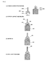
FIG. 1 is a view showing a process of fabricating a micro drill of the related art; -
FIG. 2 is a view showing a process of fabricating a micro drill of the invention; -
FIG. 3 is a view showing a variety of examples of the cross section of the recess of the drill part and the protrusion of the shank part, which are coupled to each other, in the micro drill of the invention; and -
FIG. 4 is a graph showing the shrinking behaviors of the powder compact of tungsten carbide, which is a super-hard material, and the power compact of stainless steel, which is the material of the shank part, according to temperature. - Below, a detailed description will be given of a micro drill and a method of fabricating the same of the invention with reference to the accompanying drawings.
- The method of fabricating a micro drill of the invention is a method of fabricating a micro drill, which includes a drill part for machining a hole and a shank part fixed to a motor, the drill part and the shank part being made of different materials. The method includes the steps of: forming a drill part-forming powder compact having a recess in one end thereof, and forming a shank part-forming powder compact having a protrusion, the protrusion intended to be fitted into the recess of the drill part-forming powder compact; forming an assembly of the drill part-forming powder compact and the shank part-forming powder compact, with the protrusion fitted into the recess; and simultaneously sintering the assembly of the drill part-forming powder compact and the shank part-forming powder compact.
- First, a mixture for powder sintering, which is intended to form a drill part-forming powder compact, is prepared. For this, in this embodiment, WC-8wt%Co, in which 8wt% of Co is added to tungsten carbide (WC) is used as super-hard powder. Here, TiC, TaC, VC, Cr3C2, or the like can be added in an amount of 1wt% or less according to use. In addition, cermet can be used as a super-hard material. Although super-hard powder has an average diameter of 0.2µm, powder having an average diameter less than 1µm can be added. A binder, which is used for molding, can be added if necessary. In this embodiment, 50wt% of polyethylene, 45wt% of paraffin wax, and 5wt% of stearic acid are used. The ratio of volume of the powder to the binder is 50 to 50. The mixture for powder sintering is prepared using a Banbury mixer, which is heated to 150°C.
- Afterwards, a mixture for powder sintering, which is intended to form a shank part-forming powder compact, is prepared. Here, shank part-forming stainless steel STS 420J powder is used as the powder material for the shank part. In addition, powder of an iron-based ally, such as Fe(2-8)Ni(0.2-0.8)C, STS630, STS440C, or high-speed tool steel, can be used. It is preferred that powder having an average diameter ranging from 7µm to 15µm be used. In this embodiment, the average diameter of the powder is 8µm. In addition, it is preferred that a shank part-forming material having a post-sintering hardness of 300Hv or more be used. The same binder is used as in the drill part-forming powder compact. That is, 50wt% of polyethylene, 45wt% of paraffin wax, and 5wt% of stearic acid are used. Here, the ratio of the volume of the powder to the binder is 61 to 49. The mixture for powder sintering is prepared using a Banbury mixer, which is heated at 150°C.
- Afterwards, using the mixtures for powder sintering, the drill part-forming powder compact and the shank part-forming powder compact having respective shapes are formed.
- First, referring to the step of "POWDER COMPACT PREPARATION" in
FIG. 2 , the drill part-forming powder compact 100 is formed in such a shape that it has arecess 104 formed in one end thereof. The drill part-forming powder compact 100 can be configured such that it has adrill blade portion 106 and a connectingportion 102. Thedrill blade portion 106 is configured such that it has the minimum outer diameter necessary for the machining of a drill blade after a final sintering process. Preferably, the connectingportion 102 with therecess 104 formed in one end thereof has a tapered shape such that the diameter increases in the direction away from thedrill blade portion 106. - Afterwards, the shank part-forming powder compact 200 is configured such that it has a
protrusion 204 formed on one end of abody 202. Theprotrusion 202 has a shape and a diameter such that it can be fitted into therecess 104. That is, as shown inFIG. 2 , the drill part-forming powder compact 100 is configured to surround the contour of theprotrusion 204 of the shank part-formingpowder compact 200. The diameter of therecess 104 is formed to be smaller than the outer diameter of thebody 202 of the shank part-forming powder compact 200 and to be greater than the outer diameter of theprotrusion 204. The sizes of therecess 104 and theprotrusion 204 are set in consideration of the extent to which the material used for the drill part-forming powder compact 100 and the material used for the shank part-forming powder compact 200 shrink during the sintering process. Furthermore, the cross section of therecess 104 and theprotrusion 204, which are coupled to each other, can have a variety of shapes in order to effectively transfer rotational torque of the shank, which is caused by a motor, to the drill part when the drill operates.FIG. 3 shows various examples of the shapes of therecess 104 and theprotrusion 204, which can be employed. In particular, all of parts (a) to (c) inFIG. 3 show "angled shapes," in which the part (a) shows a generally circular shape with an angled protrusion formed on a periphery thereof, the part (b) shows a generally crossed shape, and the part (c) shows a hexagonal shape. - Here, it is preferred that the drill part-forming powder compact 100 shown in
FIG. 2 be produced using Powder Injection Molding (PIM), i.e. a technology used to produce a net shape. The PIM technology is used to fabricate a three-dimensional net shape, in which substantially no after processing is required, by mixing metal or ceramic powder with binder, forming an injection-molded product from the mixture using a mold, and debinding and sintering the binder. In particular, the injection molding, which has high degree of freedom in design, is preferable, since therecess 104 is formed in one end of the drill part-formingpowder compact 100. In the case of the shank part-forming powder compact 200, compression molding can be used instead of the PIM. Here, the shank part-forming powder compact is formed as a rod, followed by machining theprotrusion 204. In particular, in the case in which the drill part-forming powder compact 100 and the shank part-forming powder compact 200 are fabricated using the PIM, therecess 104 and theprotrusion 204 having various shapes shown inFIG. 3 can be formed more easily with high precision. Furthermore, although the drill part-forming powder compact 100 and the shank part-forming powder compact 200 are formed using respective injection molding processes in this embodiment, the powder compacts can be formed and assembled through a single process using a mold having two powder nozzles. In this case, co-injection molding, in which the drill part-forming powder compact is formed through one nozzle in the state in which the shank part-forming powder compact is first formed through the other nozzle, can be used. - The
powder compacts recess 104 of the drill part being fitted into theprotrusion 204 of the shank part, and then the assembly is oriented such that the drill part-forming powder compact 100 is placed over the shank part-formingpowder compact 200. In this state, the twopowder compacts - The sintering is, preferably, vacuum sintering. The sintering temperature is suitably in the range from 1300°C to 1380°C. Here, 1300°C is the temperature at which the WC-Co alloy used in this embodiment starts to be transformed into a liquid phase, and 1380°C is the melting point of the stainless steel, the shank material. The sintering time is determined to be 4 hours or less. In the meantime, before the sintering process, a debinding process can be performed in order to remove the binder from the powder compacts. The debinding process can be room-temperature thermal decomposition, which uses nitrogen gas, hydrogen gas, or a gas in which nitrogen and hydrogen are mixed. In addition, solvent extraction, supercritical outflow, decompressing debinding, or the like can be used.
-
FIG. 4 shows the shrinking behaviors of the super-hard material (WC-Co) of the drill part and the stainless steel (STS 420J) of the shank part according to temperature. As shown inFIG. 4 , the contraction of WC-Co of the drill part starts at about 1000°C, and the stainless steel starts sintering contraction at a lower temperature than the super-hard material does. When the drill part-forming powder compact 100 and the shank part-forming powder compact 200 are sintered at the same time, the contraction start temperature of the shank part is lower than that of the drill part. Therefore, it is preferred that the protrusion be formed on the shank part and the recess be formed in the drill part such that the protrusion of the shank part is located inside the recess of the drill part in order to prevent the product from being fractured or damaged during the sintering. Furthermore, if the inner diameter of the recess of the drill part is set to be smaller than the outer diameter of the protrusion of the shank at about 0.01% to 3% after the final sintering process, it is possible to further enhance the coupling force between the drill part and the shank part. In this case, the size T1 of the inner diameter of therecess 104 of the drill part-forming powder compact 100 and the size T2 of the outer diameter of theprotrusion 204 of the shank part-forming powder compact 200 can be determined in consideration of the degree to which the sintered drill part-forming powder compact 100 shrinks and the degree to which the sintered shank part-forming powder compact 200 shrinks. - After the finally sintered compact is formed through the cosintering, a
drill blade 108 is produced by machining thedrill blade portion 106. Here, since thedrill blade portion 106 has the minimum diameter necessary for the machining of the drill blade, it is possible to minimize the waste of the super-hard material compared to the methods of the related art. When the machining of the drill blade is finished, a micro drill is produced as a final product. - Although the exemplary embodiments of the invention have been described hereinbefore, a person having ordinary skill in the art to which the invention pertains can make variations without departing from the spirit of the invention. Therefore, the foregoing descriptions of specific embodiments of the present invention are presented for purpose of illustration and description. The scope of the present invention is not defined by the detailed description as set forth above but by the accompanying claims of the invention. It should also be understood that all alterations or modifications derived from the claims or their equivalents fall within the scope of the invention.
Claims (11)
- A method of fabricating a micro drill, which includes a drill part for machining a hole and a shank part fixed to a motor, the drill part and the shank part being made of different materials, the method comprising:forming a drill part-forming powder compact having a recess in one end thereof, and forming a shank part-forming powder compact having a protrusion, the protrusion intended to be fitted into the recess of the drill part-forming powder compact;forming an assembly of the drill part-forming powder compact and the shank part-forming powder compact, with the protrusion fitted into the recess; andsimultaneously sintering the assembly of the drill part-forming powder compact and the shank part-forming powder compact.
- The method according to claim 1, wherein a size of an inner diameter of the recess formed in the drill part-forming powder compact and a size of an outer diameter of the protrusion formed in the shank part-forming powder compact are determined such that the inner diameter of the recess becomes smaller than the outer diameter of the protrusion after the powder compacts are sintered.
- The method according to claim 1 or 2, wherein the drill part-forming powder compact contains at least one selected from the group consisting of tungsten carbide powder, cobalt powder, and cermet powder, and the shank part-forming powder compact contains iron-based alloy powder that has a post-sintering hardness of 300Hv or more.
- The method according to claim 1 or 2, wherein the drill part-forming powder compact is formed using powder injection molding.
- The method according to claim 1 or 2, wherein the drill part-forming powder compact includes a drill blade portion and a connecting portion, the connecting portion having a diameter that is greater than that of the drill blade portion, and the recess is formed in one end of the connecting portion.
- The method according to claim 5, further comprising forming a drill blade by machining the drill blade portion of the micro drill after sintering the assembly.
- A micro drill comprising a drill part for machining a hole and a shank part fixed to a motor, the drill part and the shank part being made of different materials, wherein the drill part has a drill blade formed in one end thereof and a recess formed in the other end thereof, and
the shank part has a protrusion fitted into the recess of the drill part. - The micro drill according to claim 7, wherein the drill part is formed as a drill part-forming powder compact having a recess formed in one end thereof, and the shank part is formed as a shank part-forming powder compact having a recess formed in one end thereof, wherein the drill part-forming powder compact and the shank part-forming powder compact are integrated to each other by being simultaneously sintered, with the protrusion fitted into the recess.
- The micro drill according to claim 7 or 8, wherein the drill part includes a drill blade portion and a connecting portion, the connecting portion having a diameter that is greater than that of the drill blade portion, and the recess is formed in one end of the connecting portion.
- The micro drill according to claim 7 or 8, wherein the drill part-forming powder compact contains at least one selected from the group consisting of tungsten carbide powder, cobalt powder, and cermet powder, and the shank part-forming powder compact contains iron-based alloy powder that has a post-sintering hardness of 300Hv or more.
- The micro drill according to claim 7 or 8, wherein the recess and the protrusion have an angled cross section in a portion where the recess and the protrusion are coupled to each other.
Applications Claiming Priority (2)
| Application Number | Priority Date | Filing Date | Title |
|---|---|---|---|
| KR1020080065980A KR100928387B1 (en) | 2008-07-08 | 2008-07-08 | Micro drill and its manufacturing method |
| PCT/KR2009/003353 WO2010005193A2 (en) | 2008-07-08 | 2009-06-23 | Micro drill and fabricating method thereof |
Publications (3)
| Publication Number | Publication Date |
|---|---|
| EP2301694A2 true EP2301694A2 (en) | 2011-03-30 |
| EP2301694A4 EP2301694A4 (en) | 2013-02-13 |
| EP2301694B1 EP2301694B1 (en) | 2014-06-18 |
Family
ID=41507550
Family Applications (1)
| Application Number | Title | Priority Date | Filing Date |
|---|---|---|---|
| EP09794599.2A Not-in-force EP2301694B1 (en) | 2008-07-08 | 2009-06-23 | Micro drill and fabricating method thereof |
Country Status (7)
| Country | Link |
|---|---|
| US (1) | US8834077B2 (en) |
| EP (1) | EP2301694B1 (en) |
| JP (1) | JP5525520B2 (en) |
| KR (1) | KR100928387B1 (en) |
| CN (1) | CN102143813B (en) |
| RU (1) | RU2501631C2 (en) |
| WO (1) | WO2010005193A2 (en) |
Cited By (2)
| Publication number | Priority date | Publication date | Assignee | Title |
|---|---|---|---|---|
| AT513616A4 (en) * | 2013-05-28 | 2014-06-15 | Miba Sinter Austria Gmbh | Method for closing a hole |
| IT201700027841A1 (en) * | 2017-03-14 | 2018-09-14 | Boccassini S R L | PROCESS FOR TOOL PRODUCTION AND TOOLS |
Families Citing this family (18)
| Publication number | Priority date | Publication date | Assignee | Title |
|---|---|---|---|---|
| JP5067441B2 (en) * | 2009-06-30 | 2012-11-07 | イビデン株式会社 | Cutting drill and printed wiring board manufacturing method |
| DE102009028020B4 (en) * | 2009-07-27 | 2011-07-28 | Hilti Aktiengesellschaft | Drill and manufacturing process |
| DE102011000352A1 (en) * | 2011-01-27 | 2012-02-16 | Arno Friedrichs | Dental drills and method for its production |
| CN102974871A (en) * | 2012-11-27 | 2013-03-20 | 深圳市金洲精工科技股份有限公司 | Substrate for processing cutter and manufacturing method of substrate and drill bit using substrate |
| KR20150127687A (en) * | 2013-03-15 | 2015-11-17 | 산드빅 인터렉츄얼 프로퍼티 에이비 | Method of joining sintered parts of different sizes and shapes |
| KR101517140B1 (en) * | 2013-05-28 | 2015-05-04 | 한국피아이엠(주) | Manufacturing method for cemented carbide tools and cemented carbide tools thereof |
| DE102013224319A1 (en) | 2013-11-27 | 2015-06-11 | Eos Gmbh Electro Optical Systems | Method and device for the generative production of at least one component region of a component |
| CN105665717B (en) * | 2014-11-20 | 2017-07-04 | 河南省大地合金股份有限公司 | Non-solder method mini milling cutter, the production method of drill point |
| US20160229010A1 (en) * | 2015-02-09 | 2016-08-11 | Compass Corporation | Method for producing a drill bit |
| US11364540B2 (en) * | 2015-09-01 | 2022-06-21 | Kyocera Corporation | Method of manufacturing tip of cutting tool |
| CN106891010A (en) * | 2017-04-11 | 2017-06-27 | 深圳市泛海统联精密制造有限公司 | Hollow product and its metal injection moulding of use |
| EP3533545A1 (en) * | 2018-03-01 | 2019-09-04 | AB Sandvik Coromant | Modular cutting tool body and method for manufacturing the same |
| CN110977627A (en) * | 2019-12-31 | 2020-04-10 | 山东大学 | A kind of manufacturing method of cermet micro drill bit and micro drill bit |
| KR20210103118A (en) | 2020-02-13 | 2021-08-23 | 한국야금 주식회사 | Drill |
| DE112020006749T5 (en) * | 2020-02-18 | 2022-12-15 | Sumitomo Electric Industries, Ltd. | Tool main body and method for manufacturing a tool main body |
| CN111673083A (en) * | 2020-06-29 | 2020-09-18 | 丹阳市剑庐工具有限公司 | Preparation process of novel drill shank for IMPACT gun drill |
| CN113042787B (en) * | 2021-03-24 | 2022-06-21 | 武汉理工大学 | Twist drill and manufacturing method thereof |
| CN115255834A (en) * | 2022-08-05 | 2022-11-01 | 四川科力特硬质合金股份有限公司 | A Technology of Rapid Milling of Carbide Blind Holes |
Family Cites Families (34)
| Publication number | Priority date | Publication date | Assignee | Title |
|---|---|---|---|---|
| US1887372A (en) * | 1928-12-22 | 1932-11-08 | Cleveland Twist Drill Co | Cutting and forming tools, implements, and the like |
| US2334755A (en) * | 1939-12-18 | 1943-11-23 | Carbur Inc | Cutting tool |
| US2354656A (en) * | 1942-01-05 | 1944-08-01 | Annesley Griffith | Drill bit |
| US3670416A (en) * | 1970-06-29 | 1972-06-20 | Dentsply Res & Dev | Connecting metal elements and products thereof |
| US3738063A (en) * | 1971-02-05 | 1973-06-12 | J Cupler | Apparatus for making solid diamond drills |
| US4135847A (en) * | 1977-08-29 | 1979-01-23 | Tulon, Inc. | Composite drill for drilling circuit boards |
| JPS5453605A (en) * | 1977-10-06 | 1979-04-27 | Ricoh Co Ltd | Preparation of sintered parts |
| SU904894A1 (en) * | 1979-11-23 | 1982-02-15 | Новочеркасский Ордена Трудового Красного Знамени Политехнический Институт Им.С.Орджоникидзе | Combination article production method |
| US4383784A (en) * | 1980-01-07 | 1983-05-17 | Precision Twist Drill & Machine Co. | Method and means of manufacturing a rotary cutting tool |
| DE3232686A1 (en) * | 1982-09-02 | 1984-03-08 | Hartmetallwerkzeugfabrik Andreas Maier GmbH + Co KG, 7959 Schwendi | ROTATIONAL CUTTING TOOL AND METHOD FOR THE PRODUCTION THEREOF |
| KR920001585B1 (en) * | 1984-06-12 | 1992-02-20 | 스미또모 덴끼 고교 가부시끼 가이샤 | Stick compositie materials and process for preparation thereof |
| US4713286A (en) * | 1985-10-31 | 1987-12-15 | Precorp, Inc. | Printed circuit board drill and method of manufacture |
| JPS63306839A (en) * | 1987-06-06 | 1988-12-14 | Hokuriku Ceramic:Kk | Manufacture of cutting tool |
| JPH0635603B2 (en) * | 1988-03-07 | 1994-05-11 | 義信 小林 | Drilling tools such as drills and end mills, and manufacturing methods |
| SU1715497A1 (en) * | 1989-10-23 | 1992-02-28 | Донецкий политехнический институт | Method of manufacturing cutting tools |
| JPH04259306A (en) * | 1991-02-07 | 1992-09-14 | Nippon Sheet Glass Co Ltd | Production of precision parts by metal power injection molding |
| KR930003290A (en) * | 1991-07-17 | 1993-02-24 | 문정환 | Metal contact formation method and structure |
| DE19800097A1 (en) * | 1997-01-31 | 1998-08-06 | Mitsubishi Materials Corp | Manufacturing procedure for cutting tool |
| US5927912A (en) * | 1998-01-28 | 1999-07-27 | Tycom Corporation | Composite drill bit using adhesive bond |
| JP2001113406A (en) * | 1999-10-13 | 2001-04-24 | Mst Corporation:Kk | Shrink fitting tool |
| SE9903685L (en) * | 1999-10-14 | 2001-04-15 | Seco Tools Ab | Tools for rotary cutting machining, tool tip and method for making the tool tip |
| US6511265B1 (en) * | 1999-12-14 | 2003-01-28 | Ati Properties, Inc. | Composite rotary tool and tool fabrication method |
| AU2001269812A1 (en) * | 2000-06-16 | 2002-01-02 | Tayos Llc | Rotary drilling and cutting tools for manufacturing printed circuit boards |
| US20020182021A1 (en) * | 2001-05-31 | 2002-12-05 | Ha-Dih Hsieh | Cutting tool material rod for machining of printed circuit board and method of fabricating the same |
| US20030082020A1 (en) * | 2001-11-01 | 2003-05-01 | Fan-Hsien Lin | Welded micro-drill |
| IL150013A (en) * | 2002-06-04 | 2007-06-17 | Gil Hecht | Rotary cutting tool |
| DE20220679U1 (en) * | 2002-10-07 | 2004-02-12 | Schunk Gmbh & Co. Kg Fabrik Für Spann- Und Greifwerkzeuge | Turning tool, especially for micromachining, secured to spindle by clamping sleeve at rear end |
| KR100519647B1 (en) * | 2003-03-05 | 2005-10-06 | 이재철 | Manufacturing method of cemented carbide cutting tool inserts by powder injection molding |
| KR200333566Y1 (en) * | 2003-06-13 | 2003-11-15 | 박극우 | inserted drill |
| CN2936511Y (en) * | 2006-08-24 | 2007-08-22 | 高侨自动化科技股份有限公司 | Embedded micro drill |
| KR20080036681A (en) * | 2006-10-24 | 2008-04-29 | 주식회사 보림 | Regeneration method of micro drill for PCB printed circuit board processing and regeneration drill structure |
| WO2008051588A2 (en) * | 2006-10-25 | 2008-05-02 | Tdy Industries, Inc. | Articles having improved resistance to thermal cracking |
| DE112007003740T5 (en) * | 2007-12-27 | 2010-11-04 | OSG Corp., Toyokawa-shi | carbide rotary tool |
| US9358079B2 (en) * | 2010-02-11 | 2016-06-07 | Sybron Canada Lp | Bur and method of making same |
-
2008
- 2008-07-08 KR KR1020080065980A patent/KR100928387B1/en not_active Expired - Fee Related
-
2009
- 2009-06-23 US US13/003,293 patent/US8834077B2/en not_active Expired - Fee Related
- 2009-06-23 RU RU2011104189/02A patent/RU2501631C2/en not_active IP Right Cessation
- 2009-06-23 EP EP09794599.2A patent/EP2301694B1/en not_active Not-in-force
- 2009-06-23 WO PCT/KR2009/003353 patent/WO2010005193A2/en not_active Ceased
- 2009-06-23 CN CN200980134539.3A patent/CN102143813B/en not_active Expired - Fee Related
- 2009-06-23 JP JP2011517333A patent/JP5525520B2/en not_active Expired - Fee Related
Cited By (4)
| Publication number | Priority date | Publication date | Assignee | Title |
|---|---|---|---|---|
| AT513616A4 (en) * | 2013-05-28 | 2014-06-15 | Miba Sinter Austria Gmbh | Method for closing a hole |
| AT513616B1 (en) * | 2013-05-28 | 2014-06-15 | Miba Sinter Austria Gmbh | Method for closing a hole |
| US9539641B2 (en) | 2013-05-28 | 2017-01-10 | Miba Sinter Austria Gmbh | Method of closing a bore |
| IT201700027841A1 (en) * | 2017-03-14 | 2018-09-14 | Boccassini S R L | PROCESS FOR TOOL PRODUCTION AND TOOLS |
Also Published As
| Publication number | Publication date |
|---|---|
| JP5525520B2 (en) | 2014-06-18 |
| WO2010005193A3 (en) | 2010-04-01 |
| US8834077B2 (en) | 2014-09-16 |
| US20110182684A1 (en) | 2011-07-28 |
| RU2011104189A (en) | 2012-08-20 |
| JP2011527728A (en) | 2011-11-04 |
| CN102143813A (en) | 2011-08-03 |
| EP2301694B1 (en) | 2014-06-18 |
| KR100928387B1 (en) | 2009-11-23 |
| CN102143813B (en) | 2015-07-08 |
| EP2301694A4 (en) | 2013-02-13 |
| RU2501631C2 (en) | 2013-12-20 |
| WO2010005193A2 (en) | 2010-01-14 |
Similar Documents
| Publication | Publication Date | Title |
|---|---|---|
| US8834077B2 (en) | Micro drill and method of fabricating the same | |
| US7147819B2 (en) | Method for producing highly porous metallic moulded bodies close to the desired final contours | |
| CN105081330B (en) | A kind of step-like bar of the ultra-fine cemented carbide of big L/D ratio and preparation method | |
| US5487773A (en) | Process for producing sintered body and magnet base | |
| Vervoort et al. | Overview of powder injection molding | |
| US6790252B2 (en) | Tungsten-carbide articles made by metal injection molding and method | |
| EP2564956A1 (en) | Fabrication method of alloy parts by metal injection molding | |
| KR970011257B1 (en) | Watch | |
| Rota et al. | Wear resistant tools for reproduction technologies produced by micro powder metallurgy | |
| CN114086015A (en) | A kind of copper-tungsten alloy parts and manufacturing method thereof | |
| US20020037232A1 (en) | Method for controlling the dimensions of bodies made from sinterable materials | |
| WO2012111835A2 (en) | Mold and die metallic material, air-permeable member for mold and die use, and method for manufacturing the same | |
| US20020037233A1 (en) | Method for making micromolds | |
| Liu et al. | Injection molding of 316L stainless steel microstructures | |
| CN110052605B (en) | Preparation method of hard alloy functionally graded material | |
| German | Wear applications offer further growth for PIM | |
| Yin et al. | Fabrication of micro gear wheels by micropowder injection molding | |
| Yin et al. | Micro powder injection molding—large scale production technology for micro-sized components | |
| KR20100013000A (en) | Method for manufacturing a micro-drill using double heat-treatment | |
| WO1985002570A1 (en) | A method for manufacturing a tool suitable for cutting and/or shaping work, and a tool which has preferably been manufactured in accordance with the method | |
| JP7327864B1 (en) | Precision nozzle and its manufacturing method | |
| CN109047749A (en) | The preparation method of environment-friendly type cemented carbide powder feeding and hard alloy components | |
| JPH05171334A (en) | Hard sintered part and manufacturing method thereof | |
| CN111185601A (en) | Metal injection molding processing method of special-shaped notebook computer rotating shaft | |
| EP2707162A1 (en) | Liner for a die body |
Legal Events
| Date | Code | Title | Description |
|---|---|---|---|
| PUAI | Public reference made under article 153(3) epc to a published international application that has entered the european phase |
Free format text: ORIGINAL CODE: 0009012 |
|
| 17P | Request for examination filed |
Effective date: 20110110 |
|
| AK | Designated contracting states |
Kind code of ref document: A2 Designated state(s): AT BE BG CH CY CZ DE DK EE ES FI FR GB GR HR HU IE IS IT LI LT LU LV MC MK MT NL NO PL PT RO SE SI SK TR |
|
| AX | Request for extension of the european patent |
Extension state: AL BA RS |
|
| RIN1 | Information on inventor provided before grant (corrected) |
Inventor name: YOON, TAE SIK Inventor name: LEE, JAE JOON Inventor name: CHO, SOON JIN Inventor name: CHO, SEUNG HYUN |
|
| RAP1 | Party data changed (applicant data changed or rights of an application transferred) |
Owner name: BESTNER INC. |
|
| DAX | Request for extension of the european patent (deleted) | ||
| RIC1 | Information provided on ipc code assigned before grant |
Ipc: C22C 38/44 20060101ALI20121212BHEP Ipc: B22F 7/06 20060101AFI20121212BHEP Ipc: B23B 51/02 20060101ALI20121212BHEP Ipc: C22C 38/48 20060101ALI20121212BHEP Ipc: B23P 15/32 20060101ALI20121212BHEP Ipc: C22C 38/42 20060101ALI20121212BHEP |
|
| A4 | Supplementary search report drawn up and despatched |
Effective date: 20130116 |
|
| RIC1 | Information provided on ipc code assigned before grant |
Ipc: B23P 15/32 20060101ALI20130110BHEP Ipc: B23B 51/02 20060101ALI20130110BHEP Ipc: C22C 38/42 20060101ALI20130110BHEP Ipc: C22C 38/48 20060101ALI20130110BHEP Ipc: C22C 38/44 20060101ALI20130110BHEP Ipc: B22F 7/06 20060101AFI20130110BHEP |
|
| GRAP | Despatch of communication of intention to grant a patent |
Free format text: ORIGINAL CODE: EPIDOSNIGR1 |
|
| RIC1 | Information provided on ipc code assigned before grant |
Ipc: C22C 38/48 20060101ALI20131204BHEP Ipc: B23B 51/02 20060101ALI20131204BHEP Ipc: B23P 15/32 20060101ALI20131204BHEP Ipc: C22C 38/42 20060101ALI20131204BHEP Ipc: C22C 38/44 20060101ALI20131204BHEP Ipc: B22F 7/06 20060101AFI20131204BHEP Ipc: C22C 38/08 20060101ALI20131204BHEP |
|
| INTG | Intention to grant announced |
Effective date: 20140107 |
|
| GRAS | Grant fee paid |
Free format text: ORIGINAL CODE: EPIDOSNIGR3 |
|
| GRAA | (expected) grant |
Free format text: ORIGINAL CODE: 0009210 |
|
| AK | Designated contracting states |
Kind code of ref document: B1 Designated state(s): AT BE BG CH CY CZ DE DK EE ES FI FR GB GR HR HU IE IS IT LI LT LU LV MC MK MT NL NO PL PT RO SE SI SK TR |
|
| REG | Reference to a national code |
Ref country code: GB Ref legal event code: FG4D |
|
| REG | Reference to a national code |
Ref country code: CH Ref legal event code: EP |
|
| REG | Reference to a national code |
Ref country code: AT Ref legal event code: REF Ref document number: 673045 Country of ref document: AT Kind code of ref document: T Effective date: 20140715 |
|
| REG | Reference to a national code |
Ref country code: IE Ref legal event code: FG4D |
|
| REG | Reference to a national code |
Ref country code: DE Ref legal event code: R096 Ref document number: 602009024791 Country of ref document: DE Effective date: 20140731 |
|
| PG25 | Lapsed in a contracting state [announced via postgrant information from national office to epo] |
Ref country code: NO Free format text: LAPSE BECAUSE OF FAILURE TO SUBMIT A TRANSLATION OF THE DESCRIPTION OR TO PAY THE FEE WITHIN THE PRESCRIBED TIME-LIMIT Effective date: 20140918 Ref country code: FI Free format text: LAPSE BECAUSE OF FAILURE TO SUBMIT A TRANSLATION OF THE DESCRIPTION OR TO PAY THE FEE WITHIN THE PRESCRIBED TIME-LIMIT Effective date: 20140618 Ref country code: CY Free format text: LAPSE BECAUSE OF FAILURE TO SUBMIT A TRANSLATION OF THE DESCRIPTION OR TO PAY THE FEE WITHIN THE PRESCRIBED TIME-LIMIT Effective date: 20140618 Ref country code: LT Free format text: LAPSE BECAUSE OF FAILURE TO SUBMIT A TRANSLATION OF THE DESCRIPTION OR TO PAY THE FEE WITHIN THE PRESCRIBED TIME-LIMIT Effective date: 20140618 Ref country code: GR Free format text: LAPSE BECAUSE OF FAILURE TO SUBMIT A TRANSLATION OF THE DESCRIPTION OR TO PAY THE FEE WITHIN THE PRESCRIBED TIME-LIMIT Effective date: 20140919 |
|
| REG | Reference to a national code |
Ref country code: NL Ref legal event code: VDEP Effective date: 20140618 |
|
| REG | Reference to a national code |
Ref country code: AT Ref legal event code: MK05 Ref document number: 673045 Country of ref document: AT Kind code of ref document: T Effective date: 20140618 |
|
| REG | Reference to a national code |
Ref country code: LT Ref legal event code: MG4D |
|
| PG25 | Lapsed in a contracting state [announced via postgrant information from national office to epo] |
Ref country code: LV Free format text: LAPSE BECAUSE OF FAILURE TO SUBMIT A TRANSLATION OF THE DESCRIPTION OR TO PAY THE FEE WITHIN THE PRESCRIBED TIME-LIMIT Effective date: 20140618 Ref country code: HR Free format text: LAPSE BECAUSE OF FAILURE TO SUBMIT A TRANSLATION OF THE DESCRIPTION OR TO PAY THE FEE WITHIN THE PRESCRIBED TIME-LIMIT Effective date: 20140618 Ref country code: SE Free format text: LAPSE BECAUSE OF FAILURE TO SUBMIT A TRANSLATION OF THE DESCRIPTION OR TO PAY THE FEE WITHIN THE PRESCRIBED TIME-LIMIT Effective date: 20140618 |
|
| PG25 | Lapsed in a contracting state [announced via postgrant information from national office to epo] |
Ref country code: SK Free format text: LAPSE BECAUSE OF FAILURE TO SUBMIT A TRANSLATION OF THE DESCRIPTION OR TO PAY THE FEE WITHIN THE PRESCRIBED TIME-LIMIT Effective date: 20140618 Ref country code: EE Free format text: LAPSE BECAUSE OF FAILURE TO SUBMIT A TRANSLATION OF THE DESCRIPTION OR TO PAY THE FEE WITHIN THE PRESCRIBED TIME-LIMIT Effective date: 20140618 Ref country code: ES Free format text: LAPSE BECAUSE OF FAILURE TO SUBMIT A TRANSLATION OF THE DESCRIPTION OR TO PAY THE FEE WITHIN THE PRESCRIBED TIME-LIMIT Effective date: 20140618 Ref country code: PT Free format text: LAPSE BECAUSE OF FAILURE TO SUBMIT A TRANSLATION OF THE DESCRIPTION OR TO PAY THE FEE WITHIN THE PRESCRIBED TIME-LIMIT Effective date: 20141020 Ref country code: CZ Free format text: LAPSE BECAUSE OF FAILURE TO SUBMIT A TRANSLATION OF THE DESCRIPTION OR TO PAY THE FEE WITHIN THE PRESCRIBED TIME-LIMIT Effective date: 20140618 Ref country code: RO Free format text: LAPSE BECAUSE OF FAILURE TO SUBMIT A TRANSLATION OF THE DESCRIPTION OR TO PAY THE FEE WITHIN THE PRESCRIBED TIME-LIMIT Effective date: 20140618 |
|
| REG | Reference to a national code |
Ref country code: CH Ref legal event code: PL |
|
| PG25 | Lapsed in a contracting state [announced via postgrant information from national office to epo] |
Ref country code: IS Free format text: LAPSE BECAUSE OF FAILURE TO SUBMIT A TRANSLATION OF THE DESCRIPTION OR TO PAY THE FEE WITHIN THE PRESCRIBED TIME-LIMIT Effective date: 20141018 Ref country code: NL Free format text: LAPSE BECAUSE OF FAILURE TO SUBMIT A TRANSLATION OF THE DESCRIPTION OR TO PAY THE FEE WITHIN THE PRESCRIBED TIME-LIMIT Effective date: 20140618 Ref country code: AT Free format text: LAPSE BECAUSE OF FAILURE TO SUBMIT A TRANSLATION OF THE DESCRIPTION OR TO PAY THE FEE WITHIN THE PRESCRIBED TIME-LIMIT Effective date: 20140618 Ref country code: PL Free format text: LAPSE BECAUSE OF FAILURE TO SUBMIT A TRANSLATION OF THE DESCRIPTION OR TO PAY THE FEE WITHIN THE PRESCRIBED TIME-LIMIT Effective date: 20140618 |
|
| REG | Reference to a national code |
Ref country code: DE Ref legal event code: R097 Ref document number: 602009024791 Country of ref document: DE |
|
| REG | Reference to a national code |
Ref country code: IE Ref legal event code: MM4A |
|
| PG25 | Lapsed in a contracting state [announced via postgrant information from national office to epo] |
Ref country code: MC Free format text: LAPSE BECAUSE OF FAILURE TO SUBMIT A TRANSLATION OF THE DESCRIPTION OR TO PAY THE FEE WITHIN THE PRESCRIBED TIME-LIMIT Effective date: 20140618 |
|
| PLBE | No opposition filed within time limit |
Free format text: ORIGINAL CODE: 0009261 |
|
| STAA | Information on the status of an ep patent application or granted ep patent |
Free format text: STATUS: NO OPPOSITION FILED WITHIN TIME LIMIT |
|
| PG25 | Lapsed in a contracting state [announced via postgrant information from national office to epo] |
Ref country code: IT Free format text: LAPSE BECAUSE OF FAILURE TO SUBMIT A TRANSLATION OF THE DESCRIPTION OR TO PAY THE FEE WITHIN THE PRESCRIBED TIME-LIMIT Effective date: 20140618 Ref country code: DK Free format text: LAPSE BECAUSE OF FAILURE TO SUBMIT A TRANSLATION OF THE DESCRIPTION OR TO PAY THE FEE WITHIN THE PRESCRIBED TIME-LIMIT Effective date: 20140618 Ref country code: LI Free format text: LAPSE BECAUSE OF NON-PAYMENT OF DUE FEES Effective date: 20140630 Ref country code: IE Free format text: LAPSE BECAUSE OF NON-PAYMENT OF DUE FEES Effective date: 20140623 Ref country code: CH Free format text: LAPSE BECAUSE OF NON-PAYMENT OF DUE FEES Effective date: 20140630 |
|
| 26N | No opposition filed |
Effective date: 20150319 |
|
| REG | Reference to a national code |
Ref country code: DE Ref legal event code: R097 Ref document number: 602009024791 Country of ref document: DE Effective date: 20150319 |
|
| REG | Reference to a national code |
Ref country code: FR Ref legal event code: PLFP Year of fee payment: 7 |
|
| PG25 | Lapsed in a contracting state [announced via postgrant information from national office to epo] |
Ref country code: BE Free format text: LAPSE BECAUSE OF FAILURE TO SUBMIT A TRANSLATION OF THE DESCRIPTION OR TO PAY THE FEE WITHIN THE PRESCRIBED TIME-LIMIT Effective date: 20140618 |
|
| PG25 | Lapsed in a contracting state [announced via postgrant information from national office to epo] |
Ref country code: SI Free format text: LAPSE BECAUSE OF FAILURE TO SUBMIT A TRANSLATION OF THE DESCRIPTION OR TO PAY THE FEE WITHIN THE PRESCRIBED TIME-LIMIT Effective date: 20140618 |
|
| PG25 | Lapsed in a contracting state [announced via postgrant information from national office to epo] |
Ref country code: MT Free format text: LAPSE BECAUSE OF FAILURE TO SUBMIT A TRANSLATION OF THE DESCRIPTION OR TO PAY THE FEE WITHIN THE PRESCRIBED TIME-LIMIT Effective date: 20140618 |
|
| REG | Reference to a national code |
Ref country code: FR Ref legal event code: PLFP Year of fee payment: 8 |
|
| PG25 | Lapsed in a contracting state [announced via postgrant information from national office to epo] |
Ref country code: BG Free format text: LAPSE BECAUSE OF FAILURE TO SUBMIT A TRANSLATION OF THE DESCRIPTION OR TO PAY THE FEE WITHIN THE PRESCRIBED TIME-LIMIT Effective date: 20140618 |
|
| PG25 | Lapsed in a contracting state [announced via postgrant information from national office to epo] |
Ref country code: HU Free format text: LAPSE BECAUSE OF FAILURE TO SUBMIT A TRANSLATION OF THE DESCRIPTION OR TO PAY THE FEE WITHIN THE PRESCRIBED TIME-LIMIT; INVALID AB INITIO Effective date: 20090623 Ref country code: LU Free format text: LAPSE BECAUSE OF NON-PAYMENT OF DUE FEES Effective date: 20140623 Ref country code: TR Free format text: LAPSE BECAUSE OF FAILURE TO SUBMIT A TRANSLATION OF THE DESCRIPTION OR TO PAY THE FEE WITHIN THE PRESCRIBED TIME-LIMIT Effective date: 20140618 |
|
| REG | Reference to a national code |
Ref country code: DE Ref legal event code: R082 Ref document number: 602009024791 Country of ref document: DE Representative=s name: GLAWE DELFS MOLL PARTNERSCHAFT MBB VON PATENT-, DE Ref country code: DE Ref legal event code: R082 Ref document number: 602009024791 Country of ref document: DE Representative=s name: RAIBLE, DEISSLER, LEHMANN PATENTANWAELTE PARTG, DE |
|
| REG | Reference to a national code |
Ref country code: DE Ref legal event code: R082 Ref document number: 602009024791 Country of ref document: DE Ref country code: DE Ref legal event code: R082 Ref document number: 602009024791 Country of ref document: DE Representative=s name: RAIBLE, DEISSLER, LEHMANN PATENTANWAELTE PARTG, DE |
|
| REG | Reference to a national code |
Ref country code: FR Ref legal event code: PLFP Year of fee payment: 9 |
|
| PG25 | Lapsed in a contracting state [announced via postgrant information from national office to epo] |
Ref country code: MK Free format text: LAPSE BECAUSE OF FAILURE TO SUBMIT A TRANSLATION OF THE DESCRIPTION OR TO PAY THE FEE WITHIN THE PRESCRIBED TIME-LIMIT Effective date: 20140618 |
|
| PGFP | Annual fee paid to national office [announced via postgrant information from national office to epo] |
Ref country code: FR Payment date: 20181218 Year of fee payment: 10 Ref country code: GB Payment date: 20181219 Year of fee payment: 10 |
|
| PGFP | Annual fee paid to national office [announced via postgrant information from national office to epo] |
Ref country code: DE Payment date: 20181220 Year of fee payment: 10 |
|
| REG | Reference to a national code |
Ref country code: DE Ref legal event code: R119 Ref document number: 602009024791 Country of ref document: DE |
|
| GBPC | Gb: european patent ceased through non-payment of renewal fee |
Effective date: 20190623 |
|
| PG25 | Lapsed in a contracting state [announced via postgrant information from national office to epo] |
Ref country code: DE Free format text: LAPSE BECAUSE OF NON-PAYMENT OF DUE FEES Effective date: 20200101 Ref country code: GB Free format text: LAPSE BECAUSE OF NON-PAYMENT OF DUE FEES Effective date: 20190623 |
|
| PG25 | Lapsed in a contracting state [announced via postgrant information from national office to epo] |
Ref country code: FR Free format text: LAPSE BECAUSE OF NON-PAYMENT OF DUE FEES Effective date: 20190630 |