EP2301376A1 - Hair curler connector - Google Patents
Hair curler connector Download PDFInfo
- Publication number
- EP2301376A1 EP2301376A1 EP10008740A EP10008740A EP2301376A1 EP 2301376 A1 EP2301376 A1 EP 2301376A1 EP 10008740 A EP10008740 A EP 10008740A EP 10008740 A EP10008740 A EP 10008740A EP 2301376 A1 EP2301376 A1 EP 2301376A1
- Authority
- EP
- European Patent Office
- Prior art keywords
- hair curler
- connector
- lock
- buckle
- housing
- Prior art date
- Legal status (The legal status is an assumption and is not a legal conclusion. Google has not performed a legal analysis and makes no representation as to the accuracy of the status listed.)
- Granted
Links
- 210000004209 hair Anatomy 0.000 title claims abstract description 49
- 238000010438 heat treatment Methods 0.000 claims abstract description 25
- 230000008859 change Effects 0.000 description 2
- 230000004048 modification Effects 0.000 description 2
- 238000012986 modification Methods 0.000 description 2
- 239000002131 composite material Substances 0.000 description 1
- 238000005485 electric heating Methods 0.000 description 1
- 238000000034 method Methods 0.000 description 1
- 230000008569 process Effects 0.000 description 1
Images

Classifications
-
- H—ELECTRICITY
- H01—ELECTRIC ELEMENTS
- H01R—ELECTRICALLY-CONDUCTIVE CONNECTIONS; STRUCTURAL ASSOCIATIONS OF A PLURALITY OF MUTUALLY-INSULATED ELECTRICAL CONNECTING ELEMENTS; COUPLING DEVICES; CURRENT COLLECTORS
- H01R13/00—Details of coupling devices of the kinds covered by groups H01R12/70 or H01R24/00 - H01R33/00
- H01R13/62—Means for facilitating engagement or disengagement of coupling parts or for holding them in engagement
- H01R13/627—Snap or like fastening
- H01R13/6275—Latching arms not integral with the housing
-
- A—HUMAN NECESSITIES
- A45—HAND OR TRAVELLING ARTICLES
- A45D—HAIRDRESSING OR SHAVING EQUIPMENT; EQUIPMENT FOR COSMETICS OR COSMETIC TREATMENTS, e.g. FOR MANICURING OR PEDICURING
- A45D1/00—Curling-tongs, i.e. tongs for use when hot; Curling-irons, i.e. irons for use when hot; Accessories therefor
- A45D1/02—Curling-tongs, i.e. tongs for use when hot; Curling-irons, i.e. irons for use when hot; Accessories therefor with means for internal heating, e.g. by liquid fuel
- A45D1/04—Curling-tongs, i.e. tongs for use when hot; Curling-irons, i.e. irons for use when hot; Accessories therefor with means for internal heating, e.g. by liquid fuel by electricity
-
- A—HUMAN NECESSITIES
- A45—HAND OR TRAVELLING ARTICLES
- A45D—HAIRDRESSING OR SHAVING EQUIPMENT; EQUIPMENT FOR COSMETICS OR COSMETIC TREATMENTS, e.g. FOR MANICURING OR PEDICURING
- A45D1/00—Curling-tongs, i.e. tongs for use when hot; Curling-irons, i.e. irons for use when hot; Accessories therefor
- A45D1/06—Curling-tongs, i.e. tongs for use when hot; Curling-irons, i.e. irons for use when hot; Accessories therefor with two or more jaws
-
- Y—GENERAL TAGGING OF NEW TECHNOLOGICAL DEVELOPMENTS; GENERAL TAGGING OF CROSS-SECTIONAL TECHNOLOGIES SPANNING OVER SEVERAL SECTIONS OF THE IPC; TECHNICAL SUBJECTS COVERED BY FORMER USPC CROSS-REFERENCE ART COLLECTIONS [XRACs] AND DIGESTS
- Y10—TECHNICAL SUBJECTS COVERED BY FORMER USPC
- Y10T—TECHNICAL SUBJECTS COVERED BY FORMER US CLASSIFICATION
- Y10T403/00—Joints and connections
- Y10T403/59—Manually releaseable latch type
- Y10T403/599—Spring biased manipulator
Definitions
- the present invention relates to hairdressing device, more particularly, the present invention is directed to a hair curler connector adapted different heating component and facilitate changing.
- Hair curler is a common hairdressing device.
- the main portion of the hair curler includes a heating component, which engages with the hair and keep the hair in certain curl state, and it pass the heat energy to the hair to style the hair after power up.
- the technical problem of the present invention to be solved is providing a hair curler connector adapted different heating component and facilitates changing.
- the present invention provides with a hair curler connector, which includes a locking assembly and a buckle, the locking assembly including a lock and a spring assembly, with the lock being equipped with hooks engaged with the buckle.
- one of the buckle and the lock is coupled to the handle of the hair curler, and the other one is coupled to the heating component of the hair curler, whereby the hair curler connector facilitate to connect the handle with the heating component together, which is convenient for disassembly.
- the function of the spring assembly is to move or distort the lock when assembling and disassembling, so as the hooks depart from the buckles, or the hooks are inserted into the buckle for reposition.
- the lock is a elastic member to integrate with the spring assembly, and the spring assembly and the lock are one-piece structure in this case.
- the lock itself acts as an elastic member , e.g. plastic member, which makes the lock characterize of elasticity, and the lock is easy to press to be distorted when assembling and disassembling, so as the hooks depart from the buckles.
- the spring assembly includes a spring component, with one end of the spring component engaging with the lock.
- the spring component is independent of the lock. The user presses the lock when assembling and disassembling, then the elasticity of the spring component is overcome, to make the hooks depart from the buckles; elasticity of the spring component makes the lock to reposition when the user releases the lock.
- the spring component could be spring or shrapnel.
- the lock is equipped with buttons.
- the number of the lock is two or above according to the embodiment of the present invention.
- the number of the lock is two, two locks are in symmetrical arrangement, and two ends of the spring component are engaged with the locks respectively.
- the composite structure of the lock and the buckle could be: the buckle is ring shape, and stoppers are symmetrically arranged on the buckle to engage with the two hooks, with the two hooks extending far away from the centre line of the buckle ring in the direction further from the buckle respectively.
- the hair curler connector further comprises a housing, and recessions are symmetrically formed on the housing to engage with the two locks; a mounting portion is formed on the housing to receive the spring component.
- a location beam is positioned on the housing, and a location hole is formed on the buckle to engage with the location beam.
- the hair curler according to the embodiment of the present invention further comprises conductive pins adapted for electrically connecting to a heating component a hair curler; conductive bores are formed on the housing to receive the conductive pins, and the conductive bores are electrically connected to power lines under control. In this case, only when the lock is coupled to the buckle, and the conductive pins are electrically connected to the conductive bores, the heating component of the hair curler then is connected to power lines.
- the advantages of the present invention are sum up as: simple structure, easy to operate; adapted for different heating components for the convenience of changing.
- Fig. 1 is a exploded view illustrating the hair curler according to the embodiment of the present invention
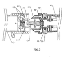
- Fig. 2 is a partial section view illustrating the hair curler (the state of the lock 2 departing from the buckle 1) according to the embodiment of the present invention shown in Fig. 1 ;
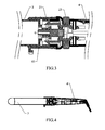
- Fig. 3 is a partial section view illustrating the hair curler (the state of the lock 2 combining to the buckle 1) according to the embodiment of the present invention shown in Fig. 1 ;
- Fig. 4 is section view illustrating the hair curler (the state of the lock 2 combining to the buckle 1) according to the embodiment of the present invention shown in Fig. 1 .
- Fig.1 , Fig.2 , Fig.3, and Fig.4 illustrate the embodiments of the present invention.
- the hair curler includes a heating component 3 and a handle 4, with the heating component 3 being connected to the handle 4 via the hair curler connector.
- the hair curler connector includes a buckle 1 and a locking assembly;
- the buckle 1 is ring shape, a stopper 11 and two symmetrical holes 12 are formed on the buckle 1;
- the locking assembly has two locks 2 and spring 10 (that is the spring component), wherein two hooks 21 are arranged on the lock 2 to engaged with the stopper 11 and the holes 12, two hooks 21 extending far away from the centre line of the buckle 1 in the direction further from the buckle 1 respectively.
- Bulges 22 are arranged on the lock 2, buttons 23 are mounted on the lock 2, and the button 23 are provided with sinkhole 231 to receive bulges 22, wherein the bulges 22 are inserted into the sinkhole 231, and the buttons 23 are explored from the outer surface of the handle 4 to facilitate operation (referring to Fig.3 ); the lock 2 is further equipped with support rods 24, with two ends of the spring 10 respectively covering on the support rods 24 to engage with the locks 2.
- the buckle 1 is mounted on the heating component 3, and the right end of two locks 2 respectively mounted on the internal wall of the handle 4 by two screws 5.
- the mounting holes 4 are formed on the outer surface of the handle 4 to receive the buttons 23.
- the handle 4 is equipped with a housing 6, two recessions 61 engaged with two locks 2 are symmetrically arranged on the housing 6 to position the locks 2; a mounting portion 62 is formed on the housing 6 to receive the spring 10.
- a location beam 63 is positioned in the center of the housing 6, and correspondingly a location hole 13 is formed in the center of the buckle 1 to engage with the location beam 63.
- conductive pins 7 are respectively electrically connected to the electric heating element within the heating component 3, and the corresponding structures are arranged on the lock 1 to position four conductive pins 7; four conductive bores 64 are formed on the housing 6 correspondingly to received four conductive pins 7 respectively, a PCB plate 8 is arranged on the housing 6 to electrically connect to power lines, four contact rings 81 are arranged on the PCB plate 8 to engaged with four conductive pins 7, wherein the contact rings 81 are electrically connected to the PCB plate 8, and the contact rings 81 are electrically connected to the PCB plate 8, with the left end of the contact ring 81 inserting into bores 64 to form the conductive bores.
- the button 23 is pressed to make the spring 10 compressed, then two hooks 21 are got closer; the handle 4 is forced to get close to the heating component 3, the location beam 63 is inserted into the location hole 13, two hooks 21 respectively run through two holes 12, and four conductive pins 7 are respectively inserted into the corresponding bores 64, until the hooks 21 are strode over the stopper 11 of the buckle 1. Meanwhile four conductive pins 7 are respectively contacted with the contact rings 81 of the bores 64, releasing the button 23, the elasticity of the spring 10 forces two hooks 21 apart, and two hooks 21 are respectively positioned on the stopper 11, and then the heating component 3 and the handle 4 are assembled together.
- the power supply is electrically connected to the heating component via the PCB plate 8, the contact rings 81, and the conductive pins 7.
- the button 23 When changing of the heating component is needed, the button 23 is pressed to make the spring 10 compressed, then two hooks 21 are got closer. Pull the handle 4 apart from the heating component 3, two hooks 21 are respectively released from the two holes 12 of the buckle 1, four conductive pins 7 are respectively released from the bores 64, until the hooks 21 are released from the buckle 1. Releasing the button 23, four conductive pins 7 are respectively released from the contact rings 81, whereby the power supply is cut off. Assemble the changed heating component 3 together with the buckle 1 and the conductive pins 7, and then assemble the heating component 3 and the handle 4 together according to the assembling process.
Landscapes
- Hair Curling (AREA)
- Connections Effected By Soldering, Adhesion, Or Permanent Deformation (AREA)
Abstract
Description
- The present invention relates to hairdressing device, more particularly, the present invention is directed to a hair curler connector adapted different heating component and facilitate changing.
- Hair curler is a common hairdressing device. The main portion of the hair curler includes a heating component, which engages with the hair and keep the hair in certain curl state, and it pass the heat energy to the hair to style the hair after power up.
- In most of the cases, hairs in different quality probably need different heating components respectively. Moreover, the heating components with different shapes or structures are requirement in order to make different hair styles. If special hair curler are respectively prepared for the hair in different quality and styles, the hair curling cost will be greatly increased.
- The technical problem of the present invention to be solved is providing a hair curler connector adapted different heating component and facilitates changing.
- In order to solve the above technical problem, the present invention provides with a hair curler connector, which includes a locking assembly and a buckle, the locking assembly including a lock and a spring assembly, with the lock being equipped with hooks engaged with the buckle.
- While the hair curler connector applying on the hair curler, one of the buckle and the lock is coupled to the handle of the hair curler, and the other one is coupled to the heating component of the hair curler, whereby the hair curler connector facilitate to connect the handle with the heating component together, which is convenient for disassembly. When changing different heating components based on the requirement of the hair curling, it only needs to change the heating component directly, and the original connector and the handle do not need to change. The function of the spring assembly is to move or distort the lock when assembling and disassembling, so as the hooks depart from the buckles, or the hooks are inserted into the buckle for reposition.
- On this basis, the other embodiments of the present invention are as follow:
- As one embodiment of the present invention, the lock is a elastic member to integrate with the spring assembly, and the spring assembly and the lock are one-piece structure in this case. The lock itself acts as an elastic member , e.g. plastic member, which makes the lock characterize of elasticity, and the lock is easy to press to be distorted when assembling and disassembling, so as the hooks depart from the buckles.
- As another embodiment of the present invention, the spring assembly includes a spring component, with one end of the spring component engaging with the lock. In this case, the spring component is independent of the lock. The user presses the lock when assembling and disassembling, then the elasticity of the spring component is overcome, to make the hooks depart from the buckles; elasticity of the spring component makes the lock to reposition when the user releases the lock. The spring component could be spring or shrapnel.
- In order to make things convenient for the user to press the lock when assembling and disassembling the heat component, the lock is equipped with buttons.
- The number of the lock is two or above according to the embodiment of the present invention.
- Preferably, the number of the lock is two, two locks are in symmetrical arrangement, and two ends of the spring component are engaged with the locks respectively.
- The composite structure of the lock and the buckle could be: the buckle is ring shape, and stoppers are symmetrically arranged on the buckle to engage with the two hooks, with the two hooks extending far away from the centre line of the buckle ring in the direction further from the buckle respectively.
- In the purpose for guaranteeing stability of the structure, the hair curler connector further comprises a housing, and recessions are symmetrically formed on the housing to engage with the two locks; a mounting portion is formed on the housing to receive the spring component.
- For the convenience of making the lock insert into the buckle, a location beam is positioned on the housing, and a location hole is formed on the buckle to engage with the location beam.
- The hair curler according to the embodiment of the present invention further comprises conductive pins adapted for electrically connecting to a heating component a hair curler; conductive bores are formed on the housing to receive the conductive pins, and the conductive bores are electrically connected to power lines under control. In this case, only when the lock is coupled to the buckle, and the conductive pins are electrically connected to the conductive bores, the heating component of the hair curler then is connected to power lines.
- The advantages of the present invention are sum up as: simple structure, easy to operate; adapted for different heating components for the convenience of changing.
- The accompanying drawings facilitate an understanding of the various embodiments of this invention. In such drawings:
-
Fig. 1 is a exploded view illustrating the hair curler according to the embodiment of the present invention; -
Fig. 2 is a partial section view illustrating the hair curler (the state of thelock 2 departing from the buckle 1) according to the embodiment of the present invention shown inFig. 1 ; -
Fig. 3 is a partial section view illustrating the hair curler (the state of thelock 2 combining to the buckle 1) according to the embodiment of the present invention shown inFig. 1 ; and -
Fig. 4 is section view illustrating the hair curler (the state of thelock 2 combining to the buckle 1) according to the embodiment of the present invention shown inFig. 1 . - Various preferred embodiments of the invention will now be described with reference to the figures, wherein like reference numerals designate similar parts throughout the various views.
-
Fig.1 ,Fig.2 ,Fig.3, and Fig.4 illustrate the embodiments of the present invention. - In order to illustrate more clearly, the whole body of the hair curler having the hair curler connector is shown in
Fig.1 ,Fig.2 ,Fig.3, and Fig.4 . The hair curler includes aheating component 3 and ahandle 4, with theheating component 3 being connected to thehandle 4 via the hair curler connector. - As shown in
Fig.1 ,Fig.2 ,Fig.3, and Fig.4 , the hair curler connector includes a buckle 1 and a locking assembly; the buckle 1 is ring shape, astopper 11 and twosymmetrical holes 12 are formed on the buckle 1; the locking assembly has twolocks 2 and spring 10 (that is the spring component), wherein twohooks 21 are arranged on thelock 2 to engaged with thestopper 11 and theholes 12, twohooks 21 extending far away from the centre line of the buckle 1 in the direction further from the buckle 1 respectively.Bulges 22 are arranged on thelock 2,buttons 23 are mounted on thelock 2, and thebutton 23 are provided withsinkhole 231 to receivebulges 22, wherein thebulges 22 are inserted into thesinkhole 231, and thebuttons 23 are explored from the outer surface of thehandle 4 to facilitate operation (referring toFig.3 ); thelock 2 is further equipped withsupport rods 24, with two ends of thespring 10 respectively covering on thesupport rods 24 to engage with thelocks 2. The buckle 1 is mounted on theheating component 3, and the right end of twolocks 2 respectively mounted on the internal wall of thehandle 4 by two screws 5. Themounting holes 4 are formed on the outer surface of thehandle 4 to receive thebuttons 23. - The
handle 4 is equipped with ahousing 6, tworecessions 61 engaged with twolocks 2 are symmetrically arranged on thehousing 6 to position thelocks 2; amounting portion 62 is formed on thehousing 6 to receive thespring 10. Alocation beam 63 is positioned in the center of thehousing 6, and correspondingly alocation hole 13 is formed in the center of the buckle 1 to engage with thelocation beam 63. - Four conductive pins 7 are respectively electrically connected to the electric heating element within the
heating component 3, and the corresponding structures are arranged on the lock 1 to position four conductive pins 7; fourconductive bores 64 are formed on thehousing 6 correspondingly to received four conductive pins 7 respectively, aPCB plate 8 is arranged on thehousing 6 to electrically connect to power lines, fourcontact rings 81 are arranged on thePCB plate 8 to engaged with four conductive pins 7, wherein thecontact rings 81 are electrically connected to thePCB plate 8, and thecontact rings 81 are electrically connected to thePCB plate 8, with the left end of thecontact ring 81 inserting intobores 64 to form the conductive bores. - Whiling assembling, referring to
Fig.2 , thebutton 23 is pressed to make thespring 10 compressed, then twohooks 21 are got closer; thehandle 4 is forced to get close to theheating component 3, thelocation beam 63 is inserted into thelocation hole 13, twohooks 21 respectively run through twoholes 12, and four conductive pins 7 are respectively inserted into thecorresponding bores 64, until thehooks 21 are strode over thestopper 11 of the buckle 1. Meanwhile four conductive pins 7 are respectively contacted with thecontact rings 81 of thebores 64, releasing thebutton 23, the elasticity of thespring 10 forces twohooks 21 apart, and twohooks 21 are respectively positioned on thestopper 11, and then theheating component 3 and thehandle 4 are assembled together. The power supply is electrically connected to the heating component via thePCB plate 8, thecontact rings 81, and the conductive pins 7. - When changing of the heating component is needed, the
button 23 is pressed to make thespring 10 compressed, then twohooks 21 are got closer. Pull thehandle 4 apart from theheating component 3, twohooks 21 are respectively released from the twoholes 12 of the buckle 1, four conductive pins 7 are respectively released from thebores 64, until thehooks 21 are released from the buckle 1. Releasing thebutton 23, four conductive pins 7 are respectively released from thecontact rings 81, whereby the power supply is cut off. Assemble the changedheating component 3 together with the buckle 1 and the conductive pins 7, and then assemble theheating component 3 and thehandle 4 together according to the assembling process. - While, it is to be understood that the invention is not to be limited to the disclosed embodiments, but on the contrary, is intended to cover various modifications and equivalent arrangements included within the spirit and scope of the invention.
- As indicated above, the invention has been described in connection with what are presently considered to be the most practical and preferred embodiments, but it is not intended to limit the scope of protection of the present invention through the above description. The field technician can easily reach all of the changes and improvements should fall within the scope of protection is not the invention, and such modifications and variations that may be apparent to those skilled in the art are intended to be included within the scope of the present invention.
Claims (10)
- A hair curler connector, comprising a locking assembly and a buckle, the locking assembly including a lock and a spring assembly, with the lock being equipped with hooks engaged with the buckle.
- The hair curler connector as claimed in claim 1, wherein the lock is an elastic member to integrate with the spring assembly.
- The hair curler connector as claimed in claim 1, wherein the spring assembly includes a spring component, with one end of the spring component engaging with the lock.
- The hair curler connector as claimed in claims 3, wherein buttons are arranged on the lock.
- The hair curler connector as claimed in claims 4, wherein the number of the lock is two or above.
- The hair curler connector as claimed in claims 3, wherein the number of the lock is two, two locks are in symmetrical arrangement, and two ends of the spring component are engaged with the locks respectively.
- The hair curler connector as claimed in claims 6, wherein the buckle is ring shape, and stoppers are symmetrically arranged on the buckle to engage with the two hooks, with the two hooks extending far away from the centre line of the buckle in the direction further from the buckle respectively.
- The hair curler connector as claimed in claims 7, wherein the hair curler connector further comprises a housing, and recessions are symmetrically formed on the housing to engage with the two locks; a mounting portion is formed on the housing to receive the spring component.
- The hair curler connector as claimed in claims 8, wherein a location beam is positioned on the housing, and a location hole is formed on the buckle to engage with the location beam.
- The hair curler connector as claimed in claims 9, wherein the hair curler connector further comprises conductive pins adapted for electrically connecting to a heating component a hair curler; conductive bores are formed on the housing to receive the conductive pins, and the conductive bores are electrically connected to power lines under control.
Applications Claiming Priority (1)
| Application Number | Priority Date | Filing Date | Title |
|---|---|---|---|
| CN200920204887.0U CN201528775U (en) | 2009-09-04 | 2009-09-04 | Hair curling rod connector |
Publications (2)
| Publication Number | Publication Date |
|---|---|
| EP2301376A1 true EP2301376A1 (en) | 2011-03-30 |
| EP2301376B1 EP2301376B1 (en) | 2015-03-04 |
Family
ID=42524188
Family Applications (1)
| Application Number | Title | Priority Date | Filing Date |
|---|---|---|---|
| EP10008740.2A Not-in-force EP2301376B1 (en) | 2009-09-04 | 2010-08-23 | Hair curler connector |
Country Status (3)
| Country | Link |
|---|---|
| US (1) | US8357005B2 (en) |
| EP (1) | EP2301376B1 (en) |
| CN (1) | CN201528775U (en) |
Cited By (3)
| Publication number | Priority date | Publication date | Assignee | Title |
|---|---|---|---|---|
| EP3854254A1 (en) | 2020-01-27 | 2021-07-28 | Kao Germany GmbH | Interlockable haircurlers for perming long hair |
| US11259612B2 (en) | 2019-09-03 | 2022-03-01 | Dongguan Lisi Intelligent Technology Co., Ltd | Power cord detachable structure for portable hair curler |
| EP4040607A1 (en) * | 2021-02-08 | 2022-08-10 | Dongguan Lisi Intelligent Technology Co., Ltd. | Power cord detachable structure for portable hair curler |
Families Citing this family (14)
| Publication number | Priority date | Publication date | Assignee | Title |
|---|---|---|---|---|
| TWM396888U (en) * | 2010-07-21 | 2011-01-21 | Wistron Corp | Lodging module and assembly for lodging module and component |
| US8348692B2 (en) * | 2010-11-30 | 2013-01-08 | John Mezzalingua Associates, Inc. | Securable multi-conductor cable connection pair having threaded insert |
| TW201301683A (en) * | 2011-06-30 | 2013-01-01 | Hon Hai Prec Ind Co Ltd | Plug and plug-socket assembly using same |
| US9203183B2 (en) * | 2013-07-30 | 2015-12-01 | GM Global Technology Operations LLC | Electrical connector assembly |
| US9368911B2 (en) | 2014-11-14 | 2016-06-14 | GM Global Technology Operations LLC | Systems and methods for self-closing electrical connector |
| EP3344548B1 (en) * | 2015-08-30 | 2020-07-01 | Oceaneering International Inc. | Rigidizing latch assembly |
| KR101637850B1 (en) * | 2015-09-08 | 2016-07-07 | 현대자동차주식회사 | Propeller shaft with locking device |
| US10927550B1 (en) * | 2018-03-29 | 2021-02-23 | Lifetime Tool & Building Products, LLC | External vents |
| CN110444976B (en) * | 2019-09-03 | 2024-10-29 | 广东丽丝智能科技有限公司 | Detachable structure of power line of portable hair curler |
| KR102392883B1 (en) * | 2020-11-06 | 2022-05-02 | 서명수 | Auto curling machine with a structure that can be rotated and detached |
| CN215776106U (en) * | 2021-01-22 | 2022-02-11 | 追觅科技(上海)有限公司 | Hair styling appliance |
| CN112821136A (en) * | 2021-02-05 | 2021-05-18 | 东莞丽丝智能科技有限公司 | Power line quick assembly disassembly structure of portable curler |
| CN217244092U (en) * | 2022-05-19 | 2022-08-23 | 北京小米移动软件有限公司 | Bendable joint, dust collector connecting pipe and dust collector |
| CN217791843U (en) * | 2022-08-11 | 2022-11-15 | 深圳市乐美科技有限公司 | Hair curler |
Citations (2)
| Publication number | Priority date | Publication date | Assignee | Title |
|---|---|---|---|---|
| US3955064A (en) * | 1974-05-23 | 1976-05-04 | Le Salon Bruno Demetrio Ltd. | Hair styling iron having interchangeable heating tips |
| DE4109069A1 (en) * | 1991-03-20 | 1992-09-24 | Petz Elektro Waerme Techn | Electric hair curling tongs - has interchangeable tong rod around outside of heating element carrier rod |
Family Cites Families (11)
| Publication number | Priority date | Publication date | Assignee | Title |
|---|---|---|---|---|
| US3779255A (en) * | 1972-12-11 | 1973-12-18 | I Theodorides | Hair curling implement |
| DE2903105C2 (en) * | 1979-01-27 | 1982-11-11 | WIK Elektro-Hausgeräte-Vertriebsgesellschaft mbH & Co Produktionskommanditgesellschaft, 4300 Essen | Hairdresser for styling, winding and drying hair |
| US4329567A (en) * | 1979-08-27 | 1982-05-11 | Clairol Incorporated | Electrically heated rotatable curler brush |
| DE3204469A1 (en) * | 1982-02-09 | 1983-09-01 | WIK Elektro-Hausgeräte-Vertriebsgesellschaft mbH & Co Produktionskommanditgesellschaft, 4300 Essen | HAIRDRESSER FOR STYLING, WINDING AND DRYING HAIR |
| US5993240A (en) * | 1997-07-29 | 1999-11-30 | Ericsson Inc. | Retention and strain relief apparatus for connecting two devices |
| JP4137677B2 (en) * | 2003-03-19 | 2008-08-20 | ミツミ電機株式会社 | Control adapter device |
| US6945666B2 (en) * | 2003-06-30 | 2005-09-20 | Monarch Instrument | Illumination device with removable power pack |
| NZ534475A (en) * | 2004-08-02 | 2007-01-26 | Tait Electronics Ltd | Battery latching assembly of portable communication device, with contacts that slide apart to latch and are squeezed together to unlatch |
| US7060910B2 (en) * | 2004-08-18 | 2006-06-13 | Airbus Deutschland Gmbh | Attachment system for an electrical device for installation in aircraft cabins |
| US7296580B1 (en) * | 2005-09-12 | 2007-11-20 | Donna Sbardella | Hair styling apparatus |
| GB2436900A (en) * | 2006-04-06 | 2007-10-10 | Kingfisher Plc | Connector with sliding sleeve |
-
2009
- 2009-09-04 CN CN200920204887.0U patent/CN201528775U/en not_active Expired - Lifetime
-
2010
- 2010-06-11 US US12/813,651 patent/US8357005B2/en active Active
- 2010-08-23 EP EP10008740.2A patent/EP2301376B1/en not_active Not-in-force
Patent Citations (2)
| Publication number | Priority date | Publication date | Assignee | Title |
|---|---|---|---|---|
| US3955064A (en) * | 1974-05-23 | 1976-05-04 | Le Salon Bruno Demetrio Ltd. | Hair styling iron having interchangeable heating tips |
| DE4109069A1 (en) * | 1991-03-20 | 1992-09-24 | Petz Elektro Waerme Techn | Electric hair curling tongs - has interchangeable tong rod around outside of heating element carrier rod |
Cited By (3)
| Publication number | Priority date | Publication date | Assignee | Title |
|---|---|---|---|---|
| US11259612B2 (en) | 2019-09-03 | 2022-03-01 | Dongguan Lisi Intelligent Technology Co., Ltd | Power cord detachable structure for portable hair curler |
| EP3854254A1 (en) | 2020-01-27 | 2021-07-28 | Kao Germany GmbH | Interlockable haircurlers for perming long hair |
| EP4040607A1 (en) * | 2021-02-08 | 2022-08-10 | Dongguan Lisi Intelligent Technology Co., Ltd. | Power cord detachable structure for portable hair curler |
Also Published As
| Publication number | Publication date |
|---|---|
| EP2301376B1 (en) | 2015-03-04 |
| US8357005B2 (en) | 2013-01-22 |
| CN201528775U (en) | 2010-07-21 |
| US20110059641A1 (en) | 2011-03-10 |
Similar Documents
| Publication | Publication Date | Title |
|---|---|---|
| US8357005B2 (en) | Hair curler connector | |
| TWM507610U (en) | Pulling member fixing structure of electric connecting terminal | |
| CN217791841U (en) | Hair curler | |
| US20240341436A1 (en) | Rotating curling iron | |
| CN115153172B (en) | hair curler | |
| CN107509326B (en) | Housing structure, mobile terminal, and assembling method of the mobile terminal | |
| TWI318025B (en) | Electrical connecting device | |
| CN109541806B (en) | Plug-in strap headset | |
| CN213405108U (en) | Wrist wearing equipment and connecting assembly thereof | |
| CN104619142A (en) | Shell structure, mobile terminal and assembly method thereof | |
| US10963071B2 (en) | Mouse | |
| CN221962974U (en) | Heat Press | |
| CN210807848U (en) | Housing assembly for electronic equipment and electronic equipment | |
| CN113168241B (en) | Joystick device and method of manufacturing the same | |
| US8544478B2 (en) | Dual gas and AC electric hair styler | |
| JP3857591B2 (en) | Microphone hanger switch structure | |
| TWM303478U (en) | Multi direction switch | |
| CN110757519B (en) | Connecting structure and shaving device | |
| CN217183595U (en) | Shell assembly and electric appliance | |
| CN107592385B (en) | Mobile terminal and its expansion module installation structure | |
| KR20140083826A (en) | Connector | |
| CN222773239U (en) | A twist-on human infrared sensing lens structure | |
| CN216316042U (en) | Quick detach subassembly and wearable equipment | |
| JP3544191B2 (en) | Energized connector between objects that move relatively | |
| CN112022646B (en) | Neck massage instrument |
Legal Events
| Date | Code | Title | Description |
|---|---|---|---|
| PUAI | Public reference made under article 153(3) epc to a published international application that has entered the european phase |
Free format text: ORIGINAL CODE: 0009012 |
|
| AK | Designated contracting states |
Kind code of ref document: A1 Designated state(s): AL AT BE BG CH CY CZ DE DK EE ES FI FR GB GR HR HU IE IS IT LI LT LU LV MC MK MT NL NO PL PT RO SE SI SK SM TR |
|
| AX | Request for extension of the european patent |
Extension state: BA ME RS |
|
| 17P | Request for examination filed |
Effective date: 20110706 |
|
| 17Q | First examination report despatched |
Effective date: 20111104 |
|
| REG | Reference to a national code |
Ref country code: DE Ref legal event code: R079 Ref document number: 602010022746 Country of ref document: DE Free format text: PREVIOUS MAIN CLASS: A45D0001040000 Ipc: H01R0013627000 |
|
| GRAP | Despatch of communication of intention to grant a patent |
Free format text: ORIGINAL CODE: EPIDOSNIGR1 |
|
| RIC1 | Information provided on ipc code assigned before grant |
Ipc: A45D 1/04 20060101ALI20141014BHEP Ipc: H01R 13/627 20060101AFI20141014BHEP Ipc: A45D 1/06 20060101ALN20141014BHEP |
|
| INTG | Intention to grant announced |
Effective date: 20141030 |
|
| GRAS | Grant fee paid |
Free format text: ORIGINAL CODE: EPIDOSNIGR3 |
|
| GRAA | (expected) grant |
Free format text: ORIGINAL CODE: 0009210 |
|
| AK | Designated contracting states |
Kind code of ref document: B1 Designated state(s): AL AT BE BG CH CY CZ DE DK EE ES FI FR GB GR HR HU IE IS IT LI LT LU LV MC MK MT NL NO PL PT RO SE SI SK SM TR |
|
| REG | Reference to a national code |
Ref country code: GB Ref legal event code: FG4D |
|
| REG | Reference to a national code |
Ref country code: CH Ref legal event code: EP |
|
| REG | Reference to a national code |
Ref country code: IE Ref legal event code: FG4D |
|
| REG | Reference to a national code |
Ref country code: AT Ref legal event code: REF Ref document number: 714581 Country of ref document: AT Kind code of ref document: T Effective date: 20150415 |
|
| REG | Reference to a national code |
Ref country code: DE Ref legal event code: R096 Ref document number: 602010022746 Country of ref document: DE Effective date: 20150416 |
|
| REG | Reference to a national code |
Ref country code: AT Ref legal event code: MK05 Ref document number: 714581 Country of ref document: AT Kind code of ref document: T Effective date: 20150304 Ref country code: NL Ref legal event code: VDEP Effective date: 20150304 |
|
| PG25 | Lapsed in a contracting state [announced via postgrant information from national office to epo] |
Ref country code: SE Free format text: LAPSE BECAUSE OF FAILURE TO SUBMIT A TRANSLATION OF THE DESCRIPTION OR TO PAY THE FEE WITHIN THE PRESCRIBED TIME-LIMIT Effective date: 20150304 Ref country code: ES Free format text: LAPSE BECAUSE OF FAILURE TO SUBMIT A TRANSLATION OF THE DESCRIPTION OR TO PAY THE FEE WITHIN THE PRESCRIBED TIME-LIMIT Effective date: 20150304 Ref country code: FI Free format text: LAPSE BECAUSE OF FAILURE TO SUBMIT A TRANSLATION OF THE DESCRIPTION OR TO PAY THE FEE WITHIN THE PRESCRIBED TIME-LIMIT Effective date: 20150304 Ref country code: NO Free format text: LAPSE BECAUSE OF FAILURE TO SUBMIT A TRANSLATION OF THE DESCRIPTION OR TO PAY THE FEE WITHIN THE PRESCRIBED TIME-LIMIT Effective date: 20150604 Ref country code: LT Free format text: LAPSE BECAUSE OF FAILURE TO SUBMIT A TRANSLATION OF THE DESCRIPTION OR TO PAY THE FEE WITHIN THE PRESCRIBED TIME-LIMIT Effective date: 20150304 Ref country code: HR Free format text: LAPSE BECAUSE OF FAILURE TO SUBMIT A TRANSLATION OF THE DESCRIPTION OR TO PAY THE FEE WITHIN THE PRESCRIBED TIME-LIMIT Effective date: 20150304 |
|
| REG | Reference to a national code |
Ref country code: LT Ref legal event code: MG4D |
|
| PG25 | Lapsed in a contracting state [announced via postgrant information from national office to epo] |
Ref country code: LV Free format text: LAPSE BECAUSE OF FAILURE TO SUBMIT A TRANSLATION OF THE DESCRIPTION OR TO PAY THE FEE WITHIN THE PRESCRIBED TIME-LIMIT Effective date: 20150304 Ref country code: GR Free format text: LAPSE BECAUSE OF FAILURE TO SUBMIT A TRANSLATION OF THE DESCRIPTION OR TO PAY THE FEE WITHIN THE PRESCRIBED TIME-LIMIT Effective date: 20150605 Ref country code: AT Free format text: LAPSE BECAUSE OF FAILURE TO SUBMIT A TRANSLATION OF THE DESCRIPTION OR TO PAY THE FEE WITHIN THE PRESCRIBED TIME-LIMIT Effective date: 20150304 |
|
| PG25 | Lapsed in a contracting state [announced via postgrant information from national office to epo] |
Ref country code: NL Free format text: LAPSE BECAUSE OF FAILURE TO SUBMIT A TRANSLATION OF THE DESCRIPTION OR TO PAY THE FEE WITHIN THE PRESCRIBED TIME-LIMIT Effective date: 20150304 |
|
| PG25 | Lapsed in a contracting state [announced via postgrant information from national office to epo] |
Ref country code: CZ Free format text: LAPSE BECAUSE OF FAILURE TO SUBMIT A TRANSLATION OF THE DESCRIPTION OR TO PAY THE FEE WITHIN THE PRESCRIBED TIME-LIMIT Effective date: 20150304 Ref country code: RO Free format text: LAPSE BECAUSE OF FAILURE TO SUBMIT A TRANSLATION OF THE DESCRIPTION OR TO PAY THE FEE WITHIN THE PRESCRIBED TIME-LIMIT Effective date: 20150304 Ref country code: SK Free format text: LAPSE BECAUSE OF FAILURE TO SUBMIT A TRANSLATION OF THE DESCRIPTION OR TO PAY THE FEE WITHIN THE PRESCRIBED TIME-LIMIT Effective date: 20150304 Ref country code: EE Free format text: LAPSE BECAUSE OF FAILURE TO SUBMIT A TRANSLATION OF THE DESCRIPTION OR TO PAY THE FEE WITHIN THE PRESCRIBED TIME-LIMIT Effective date: 20150304 Ref country code: PT Free format text: LAPSE BECAUSE OF FAILURE TO SUBMIT A TRANSLATION OF THE DESCRIPTION OR TO PAY THE FEE WITHIN THE PRESCRIBED TIME-LIMIT Effective date: 20150706 |
|
| PG25 | Lapsed in a contracting state [announced via postgrant information from national office to epo] |
Ref country code: IS Free format text: LAPSE BECAUSE OF FAILURE TO SUBMIT A TRANSLATION OF THE DESCRIPTION OR TO PAY THE FEE WITHIN THE PRESCRIBED TIME-LIMIT Effective date: 20150704 Ref country code: PL Free format text: LAPSE BECAUSE OF FAILURE TO SUBMIT A TRANSLATION OF THE DESCRIPTION OR TO PAY THE FEE WITHIN THE PRESCRIBED TIME-LIMIT Effective date: 20150304 |
|
| REG | Reference to a national code |
Ref country code: DE Ref legal event code: R097 Ref document number: 602010022746 Country of ref document: DE |
|
| PLBE | No opposition filed within time limit |
Free format text: ORIGINAL CODE: 0009261 |
|
| STAA | Information on the status of an ep patent application or granted ep patent |
Free format text: STATUS: NO OPPOSITION FILED WITHIN TIME LIMIT |
|
| PG25 | Lapsed in a contracting state [announced via postgrant information from national office to epo] |
Ref country code: DK Free format text: LAPSE BECAUSE OF FAILURE TO SUBMIT A TRANSLATION OF THE DESCRIPTION OR TO PAY THE FEE WITHIN THE PRESCRIBED TIME-LIMIT Effective date: 20150304 |
|
| 26N | No opposition filed |
Effective date: 20151207 |
|
| PG25 | Lapsed in a contracting state [announced via postgrant information from national office to epo] |
Ref country code: SI Free format text: LAPSE BECAUSE OF FAILURE TO SUBMIT A TRANSLATION OF THE DESCRIPTION OR TO PAY THE FEE WITHIN THE PRESCRIBED TIME-LIMIT Effective date: 20150304 |
|
| PG25 | Lapsed in a contracting state [announced via postgrant information from national office to epo] |
Ref country code: LU Free format text: LAPSE BECAUSE OF FAILURE TO SUBMIT A TRANSLATION OF THE DESCRIPTION OR TO PAY THE FEE WITHIN THE PRESCRIBED TIME-LIMIT Effective date: 20150823 Ref country code: MC Free format text: LAPSE BECAUSE OF FAILURE TO SUBMIT A TRANSLATION OF THE DESCRIPTION OR TO PAY THE FEE WITHIN THE PRESCRIBED TIME-LIMIT Effective date: 20150304 |
|
| REG | Reference to a national code |
Ref country code: CH Ref legal event code: PL |
|
| PG25 | Lapsed in a contracting state [announced via postgrant information from national office to epo] |
Ref country code: LI Free format text: LAPSE BECAUSE OF NON-PAYMENT OF DUE FEES Effective date: 20150831 Ref country code: CH Free format text: LAPSE BECAUSE OF NON-PAYMENT OF DUE FEES Effective date: 20150831 |
|
| REG | Reference to a national code |
Ref country code: IE Ref legal event code: MM4A |
|
| REG | Reference to a national code |
Ref country code: FR Ref legal event code: ST Effective date: 20160429 |
|
| PG25 | Lapsed in a contracting state [announced via postgrant information from national office to epo] |
Ref country code: IE Free format text: LAPSE BECAUSE OF NON-PAYMENT OF DUE FEES Effective date: 20150823 |
|
| PG25 | Lapsed in a contracting state [announced via postgrant information from national office to epo] |
Ref country code: FR Free format text: LAPSE BECAUSE OF NON-PAYMENT OF DUE FEES Effective date: 20150831 Ref country code: BE Free format text: LAPSE BECAUSE OF FAILURE TO SUBMIT A TRANSLATION OF THE DESCRIPTION OR TO PAY THE FEE WITHIN THE PRESCRIBED TIME-LIMIT Effective date: 20150304 |
|
| PG25 | Lapsed in a contracting state [announced via postgrant information from national office to epo] |
Ref country code: MT Free format text: LAPSE BECAUSE OF FAILURE TO SUBMIT A TRANSLATION OF THE DESCRIPTION OR TO PAY THE FEE WITHIN THE PRESCRIBED TIME-LIMIT Effective date: 20150304 |
|
| PG25 | Lapsed in a contracting state [announced via postgrant information from national office to epo] |
Ref country code: BG Free format text: LAPSE BECAUSE OF FAILURE TO SUBMIT A TRANSLATION OF THE DESCRIPTION OR TO PAY THE FEE WITHIN THE PRESCRIBED TIME-LIMIT Effective date: 20150304 Ref country code: HU Free format text: LAPSE BECAUSE OF FAILURE TO SUBMIT A TRANSLATION OF THE DESCRIPTION OR TO PAY THE FEE WITHIN THE PRESCRIBED TIME-LIMIT; INVALID AB INITIO Effective date: 20100823 Ref country code: SM Free format text: LAPSE BECAUSE OF FAILURE TO SUBMIT A TRANSLATION OF THE DESCRIPTION OR TO PAY THE FEE WITHIN THE PRESCRIBED TIME-LIMIT Effective date: 20150304 |
|
| PG25 | Lapsed in a contracting state [announced via postgrant information from national office to epo] |
Ref country code: CY Free format text: LAPSE BECAUSE OF FAILURE TO SUBMIT A TRANSLATION OF THE DESCRIPTION OR TO PAY THE FEE WITHIN THE PRESCRIBED TIME-LIMIT Effective date: 20150304 |
|
| PG25 | Lapsed in a contracting state [announced via postgrant information from national office to epo] |
Ref country code: TR Free format text: LAPSE BECAUSE OF FAILURE TO SUBMIT A TRANSLATION OF THE DESCRIPTION OR TO PAY THE FEE WITHIN THE PRESCRIBED TIME-LIMIT Effective date: 20150304 |
|
| PG25 | Lapsed in a contracting state [announced via postgrant information from national office to epo] |
Ref country code: MK Free format text: LAPSE BECAUSE OF FAILURE TO SUBMIT A TRANSLATION OF THE DESCRIPTION OR TO PAY THE FEE WITHIN THE PRESCRIBED TIME-LIMIT Effective date: 20150304 |
|
| PG25 | Lapsed in a contracting state [announced via postgrant information from national office to epo] |
Ref country code: AL Free format text: LAPSE BECAUSE OF FAILURE TO SUBMIT A TRANSLATION OF THE DESCRIPTION OR TO PAY THE FEE WITHIN THE PRESCRIBED TIME-LIMIT Effective date: 20150304 |
|
| PGFP | Annual fee paid to national office [announced via postgrant information from national office to epo] |
Ref country code: GB Payment date: 20200824 Year of fee payment: 11 Ref country code: DE Payment date: 20200520 Year of fee payment: 11 |
|
| PGFP | Annual fee paid to national office [announced via postgrant information from national office to epo] |
Ref country code: IT Payment date: 20200831 Year of fee payment: 11 |
|
| REG | Reference to a national code |
Ref country code: DE Ref legal event code: R119 Ref document number: 602010022746 Country of ref document: DE |
|
| GBPC | Gb: european patent ceased through non-payment of renewal fee |
Effective date: 20210823 |
|
| PG25 | Lapsed in a contracting state [announced via postgrant information from national office to epo] |
Ref country code: IT Free format text: LAPSE BECAUSE OF NON-PAYMENT OF DUE FEES Effective date: 20210823 Ref country code: GB Free format text: LAPSE BECAUSE OF NON-PAYMENT OF DUE FEES Effective date: 20210823 Ref country code: DE Free format text: LAPSE BECAUSE OF NON-PAYMENT OF DUE FEES Effective date: 20220301 |