EP2300248B1 - Gas spring piston with partial bellows support feature and gas spring assembly including same - Google Patents
Gas spring piston with partial bellows support feature and gas spring assembly including same Download PDFInfo
- Publication number
- EP2300248B1 EP2300248B1 EP09758974.1A EP09758974A EP2300248B1 EP 2300248 B1 EP2300248 B1 EP 2300248B1 EP 09758974 A EP09758974 A EP 09758974A EP 2300248 B1 EP2300248 B1 EP 2300248B1
- Authority
- EP
- European Patent Office
- Prior art keywords
- side wall
- gas spring
- piston
- spring assembly
- outer side
- Prior art date
- Legal status (The legal status is an assumption and is not a legal conclusion. Google has not performed a legal analysis and makes no representation as to the accuracy of the status listed.)
- Not-in-force
Links
- 230000007704 transition Effects 0.000 claims description 9
- 238000005096 rolling process Methods 0.000 claims description 6
- 238000006073 displacement reaction Methods 0.000 claims description 2
- 239000007789 gas Substances 0.000 description 88
- 230000000712 assembly Effects 0.000 description 21
- 238000000429 assembly Methods 0.000 description 21
- 239000000725 suspension Substances 0.000 description 17
- 239000011324 bead Substances 0.000 description 9
- 238000010276 construction Methods 0.000 description 9
- 239000012530 fluid Substances 0.000 description 6
- 230000004308 accommodation Effects 0.000 description 5
- 238000004891 communication Methods 0.000 description 5
- 125000006850 spacer group Chemical group 0.000 description 5
- IJGRMHOSHXDMSA-UHFFFAOYSA-N Atomic nitrogen Chemical compound N#N IJGRMHOSHXDMSA-UHFFFAOYSA-N 0.000 description 2
- 230000007423 decrease Effects 0.000 description 2
- 238000013461 design Methods 0.000 description 2
- 230000013011 mating Effects 0.000 description 2
- 238000012546 transfer Methods 0.000 description 2
- 230000005540 biological transmission Effects 0.000 description 1
- 239000004020 conductor Substances 0.000 description 1
- 238000013016 damping Methods 0.000 description 1
- 230000003247 decreasing effect Effects 0.000 description 1
- 230000001419 dependent effect Effects 0.000 description 1
- 238000009434 installation Methods 0.000 description 1
- 238000012423 maintenance Methods 0.000 description 1
- 230000014759 maintenance of location Effects 0.000 description 1
- 238000004519 manufacturing process Methods 0.000 description 1
- 239000000463 material Substances 0.000 description 1
- 229910052757 nitrogen Inorganic materials 0.000 description 1
- 238000013022 venting Methods 0.000 description 1
Images




Classifications
-
- B—PERFORMING OPERATIONS; TRANSPORTING
- B60—VEHICLES IN GENERAL
- B60G—VEHICLE SUSPENSION ARRANGEMENTS
- B60G11/00—Resilient suspensions characterised by arrangement, location or kind of springs
- B60G11/26—Resilient suspensions characterised by arrangement, location or kind of springs having fluid springs only, e.g. hydropneumatic springs
- B60G11/27—Resilient suspensions characterised by arrangement, location or kind of springs having fluid springs only, e.g. hydropneumatic springs wherein the fluid is a gas
-
- B—PERFORMING OPERATIONS; TRANSPORTING
- B60—VEHICLES IN GENERAL
- B60G—VEHICLE SUSPENSION ARRANGEMENTS
- B60G11/00—Resilient suspensions characterised by arrangement, location or kind of springs
- B60G11/26—Resilient suspensions characterised by arrangement, location or kind of springs having fluid springs only, e.g. hydropneumatic springs
- B60G11/28—Resilient suspensions characterised by arrangement, location or kind of springs having fluid springs only, e.g. hydropneumatic springs characterised by means specially adapted for attaching the spring to axle or sprung part of the vehicle
-
- F—MECHANICAL ENGINEERING; LIGHTING; HEATING; WEAPONS; BLASTING
- F16—ENGINEERING ELEMENTS AND UNITS; GENERAL MEASURES FOR PRODUCING AND MAINTAINING EFFECTIVE FUNCTIONING OF MACHINES OR INSTALLATIONS; THERMAL INSULATION IN GENERAL
- F16F—SPRINGS; SHOCK-ABSORBERS; MEANS FOR DAMPING VIBRATION
- F16F9/00—Springs, vibration-dampers, shock-absorbers, or similarly-constructed movement-dampers using a fluid or the equivalent as damping medium
- F16F9/02—Springs, vibration-dampers, shock-absorbers, or similarly-constructed movement-dampers using a fluid or the equivalent as damping medium using gas only or vacuum
- F16F9/04—Springs, vibration-dampers, shock-absorbers, or similarly-constructed movement-dampers using a fluid or the equivalent as damping medium using gas only or vacuum in a chamber with a flexible wall
- F16F9/05—Springs, vibration-dampers, shock-absorbers, or similarly-constructed movement-dampers using a fluid or the equivalent as damping medium using gas only or vacuum in a chamber with a flexible wall the flexible wall being of the rolling diaphragm type
- F16F9/057—Springs, vibration-dampers, shock-absorbers, or similarly-constructed movement-dampers using a fluid or the equivalent as damping medium using gas only or vacuum in a chamber with a flexible wall the flexible wall being of the rolling diaphragm type characterised by the piston
-
- B—PERFORMING OPERATIONS; TRANSPORTING
- B60—VEHICLES IN GENERAL
- B60G—VEHICLE SUSPENSION ARRANGEMENTS
- B60G2204/00—Indexing codes related to suspensions per se or to auxiliary parts
- B60G2204/10—Mounting of suspension elements
- B60G2204/12—Mounting of springs or dampers
- B60G2204/126—Mounting of pneumatic springs
-
- B—PERFORMING OPERATIONS; TRANSPORTING
- B60—VEHICLES IN GENERAL
- B60G—VEHICLE SUSPENSION ARRANGEMENTS
- B60G2206/00—Indexing codes related to the manufacturing of suspensions: constructional features, the materials used, procedures or tools
- B60G2206/01—Constructional features of suspension elements, e.g. arms, dampers, springs
- B60G2206/014—Constructional features of suspension elements, e.g. arms, dampers, springs with reinforcing nerves or branches
-
- B—PERFORMING OPERATIONS; TRANSPORTING
- B60—VEHICLES IN GENERAL
- B60G—VEHICLE SUSPENSION ARRANGEMENTS
- B60G2206/00—Indexing codes related to the manufacturing of suspensions: constructional features, the materials used, procedures or tools
- B60G2206/01—Constructional features of suspension elements, e.g. arms, dampers, springs
- B60G2206/40—Constructional features of dampers and/or springs
- B60G2206/42—Springs
- B60G2206/424—Plunger or top retainer construction for bellows or rolling lobe type air springs
-
- B—PERFORMING OPERATIONS; TRANSPORTING
- B60—VEHICLES IN GENERAL
- B60G—VEHICLE SUSPENSION ARRANGEMENTS
- B60G2206/00—Indexing codes related to the manufacturing of suspensions: constructional features, the materials used, procedures or tools
- B60G2206/01—Constructional features of suspension elements, e.g. arms, dampers, springs
- B60G2206/70—Materials used in suspensions
- B60G2206/71—Light weight materials
- B60G2206/7101—Fiber-reinforced plastics [FRP]
-
- B—PERFORMING OPERATIONS; TRANSPORTING
- B60—VEHICLES IN GENERAL
- B60G—VEHICLE SUSPENSION ARRANGEMENTS
- B60G2206/00—Indexing codes related to the manufacturing of suspensions: constructional features, the materials used, procedures or tools
- B60G2206/01—Constructional features of suspension elements, e.g. arms, dampers, springs
- B60G2206/80—Manufacturing procedures
- B60G2206/81—Shaping
- B60G2206/8101—Shaping by casting
- B60G2206/81012—Shaping by casting by injection moulding
-
- B—PERFORMING OPERATIONS; TRANSPORTING
- B60—VEHICLES IN GENERAL
- B60G—VEHICLE SUSPENSION ARRANGEMENTS
- B60G2500/00—Indexing codes relating to the regulated action or device
- B60G2500/20—Spring action or springs
Definitions
- the subject matter of the present disclosure broadly relates to the art of gas spring devices and, more particularly, to a gas spring assembly according to the preamble of claim 1. Examples of such gas spring assemblies are shown in documents DE 101 49 057 A1 , US 6 386 524 B1 and in DE 20 2005 007933 U1 .
- a gas spring assembly comprising the characterizing part of claim 1 is shown in the published patent application EP 2 093 082 A1 , this document is only prior art under Article 54(3) EPC however.
- Gas spring assemblies of various kinds and constructions are well known and commonly used in vehicle suspension systems, industrial machinery as well as other equipment and devices to provide dynamic load support between sprung and unsprung masses associated therewith.
- a typical gas spring assembly includes two opposing end members with a flexible wall or sleeve secured between the two end members that at least partially define a spring chamber.
- a quantity of pressurized gas, usually air, is contained within the spring chamber and acts on the spaced end members as well as opposing portions of the flexible wall to support the load of the sprung mass or a force that is otherwise applied to the gas spring assembly.
- gas spring assemblies are well suited for supporting loads acting axially (i.e., longitudinally between the opposed end members thereof), but that only a minimal lateral load, if any, can be supported by a typical gas spring assembly.
- applications that are normally identified as being well suited for the use of gas spring assemblies primarily involve the transfer of axially applied loads.
- arrangements for securing the gas spring assembly to a corresponding structural member in a way that provides sufficient axial support commonly include the use of threaded fasteners, fixed mounting studs with threaded nuts and/or snap together-type connections.
- the action of the gas spring assembly itself can generate lateral load conditions on one or more of the end members thereof.
- the flexible wall is urged outwardly toward the open end of the included angle between the end members. This action can generate a lateral load acting on one or both of the end members.
- many known securement arrangements having been designed to withstand axially-applied loads, as discussed above, are less well suited for use under lateral or shear loads. Therefore, a need exists for an improved arrangement for engaging an end member of a gas spring assembly with a corresponding structural member such that the interface can withstand the aforementioned lateral load conditions, such as may be encountered by a vehicle suspension system, for example.
- U.S. Patent No. 5,342,139 discloses an attachment device for mounting an end member of an air spring assembly on a corresponding support component.
- U.S. Patent No. 6,752,407 discloses a multi-component and mounting plate arrangement for securing an air spring along a structural component.
- U.S. Patent No. 6,945,548 discloses a spacer that is adapted to engage the air spring assembly and includes a winged portion that engages a slot in the corresponding structural component.
- U.S. Patent Application Publication No. 2006/0055094 discloses an air spring with end members having snap-in attachments for engaging the corresponding structural members.
- attachment and/or other features of suspension components of vehicles are often disposed within approximately the same area in which a gas spring assembly of a suspension system also resides.
- accommodations are often provided on one or more components of gas spring assemblies to help avoid interference with the attachment and/or other features while permitting the component of the gas spring assembly to be mounted or otherwise secured to a suspension component in that same area.
- Such accommodations are commonly used in association with gas spring assemblies of the rolling lobe-type, which typically include a piston that has an outer side wall and flexible sleeve that is secured along the piston such that a lobe formed thereby can roll along the outer side wall as the gas spring assembly undergoes displacement.
- the outer side wall of the piston can be supported or otherwise disposed in vertically spaced relation to the associated structural component along which the piston is secured.
- the piston of the gas spring assembly can include a bottom or end wall that the abuttingly engages the associated structural component with the nearest end of the outer side wall being disposed in spaced relation to the bottom wall.
- a spacer or other suitable component can be positioned and secured between the piston of the gas spring assembly and the associated structural component to space the end of the outer side wall a distance from the associated structural component.
- a gas spring assembly in accordance with the subject matter of the present invention is defined in claim 1.
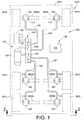
- FIG. 1 illustrates a suspension system 100 disposed between a sprung mass, such as an associated vehicle body BDY, for example, and an unsprung mass, such as an associated wheel WHL or an associated wheel-engaging member WEM, for example, of an associated vehicle VHC.
- a suspension system can include any number of one or more systems, components and/or devices and that the same can be operatively connected between the sprung and unsprung masses of the associated vehicle in any suitable manner.
- such a suspension system can include a plurality of damping members (not shown), which can be operatively connected between the sprung and unsprung masses of the associated vehicle in any suitable manner.
- suspension system 100 can include a plurality of gas spring assemblies that are supported between the sprung and unsprung masses of associated vehicle VHC.
- suspension system 100 includes six gas spring assemblies 102, one or more of which is disposed toward each corner of the associated vehicle adjacent a corresponding wheel WHL thereof.
- any other suitable number of gas spring assemblies 102 could alternately be used and that such gas spring assemblies can be disposed in any other suitable configuration or arrangement.
- gas spring assemblies 102 include a first or upper end member, such as a bead plate 104, for example, a second or lower end member, such as piston 106, for example, and a flexible wall, such as an elongated sleeve 108, for example, that is secured therebetween in a substantially fluid-tight manner.
- a first or upper end member such as a bead plate 104
- a second or lower end member such as piston 106
- a flexible wall such as an elongated sleeve 108, for example, that is secured therebetween in a substantially fluid-tight manner.
- gas spring assemblies shown and described herein are of a rolling lobe-type construction.
- gas spring assemblies can be operatively connected between the sprung and unsprung masses of an associated vehicle in any suitable manner.
- gas spring assemblies 102 are shown in FIG. 2 as being operatively connected between wheel-engaging members WEM and body BDY of associated vehicle VHC.
- WEM wheel-engaging members
- body BDY body BDY of associated vehicle VHC.
- FIG. 2 the configuration of vehicle VHC in FIG. 2 is merely a schematic representation of the structural components of the sprung and unsprung masses of the vehicle. Thus, it will be understood that this schematic representation is provided for purposes of discussion and ease of understanding and is not intended to be in any way limiting.
- wheel-engaging members WEM are shown as being pivotally attached to structural components STL such that the wheel-engaging members move through an angle AG1 relative to body BDY as wheels WHL undergo vertical movements (e.g., jounce and rebound actions), which movements are represented in FIG. 2 by arrow AR1.
- angle AG1 between the body and the corresponding wheel-engaging member will increase and gas spring assembly 102, which is operatively connected therebetween, will become elongated.
- angle AG1 will decrease and gas spring assembly 102 will become compressed. Due, at least in part, to the body and wheel-engaging member acting on the gas spring assembly at an angle to one another, gas spring assembly 102 will normally be pinched, squeezed or otherwise biased toward the open end of angle AG1, as is represented by arrow AR2.
- This biasing action results in the generation of forces that act laterally on the opposing end members of the gas spring assembly (e.g., bead plate 104 and piston 106 ), as is indicated by arrows AR3 and AR4, respectively, in FIG. 2 .
- the biasing action acts to urge the end members of the gas spring assembly in a laterally-outward direction, such as toward wheels WHL, for example.
- gas spring assemblies It is common practice for gas spring assemblies to be secured to the associated sprung and unsprung masses in a manner suitable for withstanding longitudinally (i.e., axially) acting forces or loads. Additionally, it will be appreciated that securement components and/or features of a wide variety of types, kinds, configurations and/or constructions have been used to secure the end members of the gas spring assemblies to the vehicle components in the longitudinal (i.e., axial) direction. In many such known mounting arrangements, one or more fasteners or other securement elements will pass through an opening in the structural component on which the end member is supported to engage the end member and thereby secure the gas spring assembly to the structural component.
- bracket 110 extending around three sides of wheel-engaging member WEM with piston 106 being secured thereto by way of fasteners 112 (only one of which is shown) that interconnect bracket 110 and piston 106 to thereby secure the gas spring assembly on or along the structural component (e.g., wheel-engaging member WEM ).
- a cooperative mounting arrangement in which an end member of a gas spring assembly and a corresponding vehicle component associated therewith interengage one another.
- the aforementioned laterally-acting forces associated with the pinching action can be transferred from the end member to the corresponding structural component without undesirably effecting the gas spring assembly.
- a cooperative mounting arrangement in accordance with the subject matter of the present disclosure may find particular application and use in connection with external mounting or clamping arrangements that extend along the exterior of the wheel-engaging member (or other vehicle component) and are secured thereto without the use of elements (e.g., a fastener or other securement device) that extend through the wheel-engaging member (or other vehicle component).
- a cooperative mounting arrangement 114 can include a projection 116 ( FIG. 3 ) extending from wheel-engaging member WEM and a recess or pocket 118 ( FIG. 3 ) formed into an end member, such as piston 106, for example, of the gas spring assembly or another component operatively associated therewith, such as a spacer, for example.
- Such a cooperative mounting arrangement permits the end member of the gas spring assembly and the wheel-engaging member (or other vehicle component) to interengage one another and thereby maintain the position of the end member relative to the wheel-engaging member (or other vehicle component) under any laterally acting forces, such as may be generated by the above-discussed compressing or pinching action of the vehicle components, for example.
- Suspension system 100 can also optionally include a pressurized gas supply system 120 that is operatively associated with the gas spring assemblies for selectively supplying pressurized gas (e.g., air) thereto and selectively transferring pressurized gas therefrom.
- gas supply system 120 includes a pressurized gas source, such as a compressor 122, for example, for generating pressurized air or other gases.
- the gas supply system can also include any number of one or more control devices of any suitable type, kind and/or construction that may be capable of affecting the selective transfer of pressurized gas.
- a valve assembly 124 is shown as being in communication with compressor 122 and can be of any suitable configuration or arrangement.
- valve assembly 124 includes a valve block 126 with a plurality of valves 128 supported thereon.
- Valve assembly 124 can also optionally include a suitable exhaust, such as a muffler 130, for example, for venting pressurized gas from the system.
- pressurized gas supply system 120 can also include a reservoir 132 in fluid communication with valve assembly 124 and suitable for storing pressurized gas.
- the one or more control devices can be in communication with gas spring assemblies 102 in any suitable manner, such as, for example, through suitable fluid transmission lines 134.
- pressurized gas can be selectively transmitted to and/or from the gas springs through valve assembly 124, such as to alter or maintain vehicle height at one or more corners of the vehicle, for example.
- Suspension system 100 also includes a control system 136 that is capable of communication with any one or more other systems and/or components (not shown) of suspension system 100 and/or of which VHC and is capable of selective operation and control of the suspension system.
- Control system 136 includes a controller or electronic control unit (ECU) 138 in communication with compressor 122 and/or valve assembly 124, such as through a suitable conductor or lead (not shown), for example, for selective operation and control thereof, including supplying and exhausting pressurized fluid to and from gas spring assemblies 102.
- ECU electronice control unit
- controller 138 can be of any suitable type, kind and/or configuration.
- Control system 136 can also optionally include one or more height or distance sensing devices (not shown) as well as any other desired systems and/or components.
- Such height sensors are preferably capable of generating or otherwise outputting a signal having a relation to a height or distance, such as between spaced components of the vehicle, for example.
- any such optional height sensors or any other distance-determining devices can be of any suitable type, kind, construction and/or configuration, such as mechanical linkage sensors, ultrasonic wave sensors or electromagnetic wave sensors, such as may operate using ultrasonic or electromagnetic waves, for example.
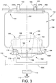
- gas spring assembly 102 includes a central axis AX that extends longitudinally between the first end member (e.g., bead plate 104 ), which is disposed toward one end of axis AX, and the opposing second end member (e.g., piston 106 ), which is spaced from the first end member toward another end of axis AX.
- the first end member is disposed along a first or upper structural component FSC, such as a vehicle body or chassis, for example, and can be adapted for securement thereto in any suitable manner.
- first structural component FSC is shown in FIG. 3 as including holes or openings OPN that are suitable for securement of the first end member to the first structural component.
- Gas spring assembly 102 is shown as including mounting studs 140 that project axially-outwardly from bead plate 104 and extend through openings OPN in the first structural component.
- Suitable fastening elements such as threaded nuts (not shown), for example, can be used to secure bead plate 104 to first structural component FSC. It will be recognized that such a mounting arrangement will generally be sufficient to oppose any lateral loads or forces acting on the first end member (e.g., bead plate 104 ), such as the lateral forces represented by arrow AR3 in FIG. 2 , for example.
- the second end member is disposed along a second or lower structural component SSC, such as an axle or other wheel-engaging member, for example, and is adapted for securement on or along this second structural component.
- the second end member is adapted for securement to the second structural component by way of an external mounting bracket or other component or arrangement that does not rely upon the use of fasteners extending through the second structural component.
- an external mounting arrangement is shown in FIGS. 2 and 3 as bracket 110 and fasteners 112.
- any other suitable arrangement could alternately be used.
- At least one of the end members of a gas spring assembly and a corresponding one of the structural components associated therewith include a cooperative mounting arrangement (e.g., cooperative mounting arrangement 114 ) suitable for accommodating laterally-acting forces, such as have been previously described, for example.
- a cooperative mounting arrangement e.g., cooperative mounting arrangement 114
- such a cooperative mounting arrangement will be used in cases in which an external mounting bracket or other arrangement is employed that does not rely upon the use of fasteners that extend through openings in the associated structural component, such as the external mounting arrangement in FIGS. 2 and 3 using bracket 110 and fasteners 112, for example. It will be appreciated that the use of such a cooperative mounting arrangement can act to oppose any such laterally-acting forces, which may not be sufficiently accommodated by an external mounting arrangement acting alone.
- the opposing end members e.g., bead plate 104 and piston 106
- the flexible wall e.g., flexible sleeve 108
- the flexible wall e.g., flexible sleeve 108
- the subject matter of the present disclosure is capable of broad use in association with any suitable type, kind, and/or configuration of gas spring assembly.
- the flexible wall (e.g., flexible sleeve 108 ) can be secured between the first and second end members in any suitable manner.
- flexible sleeve 108 extends between opposing ends 144 and 146.
- End 144 is shown as being an open end that is connected along bead plate 104 using a crimped arrangement to form a substantially fluid tight seal between the bead plate and the end of the flexible sleeve.
- End 146 of the flexible sleeve is received on a portion of piston 106 and is secured thereon by way of a snap-fit connection.
- Pressurized gas can be communicated into and out of spring chamber 142 in any suitable manner, such as, for example, through a passage 148 extending through one of mounting studs 140.
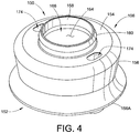
- exemplary piston 106 extends axially between opposing first and second ends, which are generally represented by reference numbers 150 and 152, respectively.
- First end 150 includes a first end wall 154 that is adapted to abuttingly engage flexible sleeve 108 and an outer side wall 156 that extends from along end wall 154 toward second end 152 of the piston.
- Outer side wall 156 is shown as having a curvilinear shape or configuration. However, it will be appreciated that any suitable size, shape and/or configuration could alternately be used, such as a frustoconical or a cylindrical shape, for example.
- outer side wall 156 will include a radially-outermost side wall portion that at least partially defines the outermost radial extent of the piston. In the exemplary embodiment shown in FIGS. 3-8 , this radially-outmost side wall portion is identified by reference number 156A and will have an overall dimension (not shown) representing the maximum diameter or width of the radially-outermost side wall portion.
- An axially-extending annular wall 158 projects from along end wall 154 generally opposite the direction of outer side wall 156 and can be dimensioned to cooperatively receive an open end (e.g., second end 146 ) of the flexible wall associated therewith.
- a radially outwardly-extending projection or lip 160 is shown as being disposed along annular wall 158 and can operate to at least partially maintain second end 146 on annular wall 158. It will be appreciated, however, that any suitable configuration and/or arrangement can alternately be used for securement of the flexible wall on or along the piston and, thus, that annular wall 158 and lip 160 are optional.
- Piston 106 also includes a second end wall 162 that is disposed along second end 152 and adapted to cooperatively engage second structural component SSC.
- second end wall 162 is approximately planar and adapted to abuttingly engage second structural component SSC.
- Piston 106 further includes an inner side wall 164 that at least partially defines an inner cavity 166.
- inner side wall 164 extends in an approximately longitudinal direction and generally between first and second end walls 154 and 162.
- Inner side wall 164 is disposed in radially inwardly-spaced relation to outer side wall 156 such that an outer cavity 168 is formed therebetween.
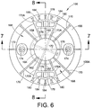
- a plurality of outwardly-extending support walls 170 extend between the inner and outer side walls and thereby structurally interconnect the same.
- inner support walls 172 can optionally be included within inner cavity 166, such as, for example, along second end wall 162 and extending generally between different portions of inner side wall 164.
- Support walls 170 can be of any suitable quantity, configuration and/or arrangement and can extend along any portion of the longitudinal length of piston 106.
- outer support walls 170 extend radially-outwardly from inner side wall 164 and along approximately the entire longitudinal length of outer side wall 156 such that outer cavity 168 is separated into a plurality of individual chambers (not numbered).
- any other number, arrangement and/or configuration of inner support walls 172 and/or outer support walls 170 can alternately be used.
- Piston 106 also includes at least one securement feature suitable for at least partially securing the piston on or along the corresponding structural component.
- piston 106 includes a plurality of passages 174 that extend through the piston and are suitable for receiving at least a portion of a fastener, such as fastener 112, for example.
- Mating fastener components such as threaded nuts (not shown), for example, could be received within a portion of passages 174 or, alternately, mating threads (not shown) could be provided within the passage, either directly in the piston material or in the form of threaded inserts (not shown) embedded within the piston. It will be appreciated, however, that any other suitable arrangement could alternately be used, such as the use of mounting studs (not shown) projecting from the piston, for example.
- piston 106 includes at least one mounting feature adapted to cooperatively engage a corresponding mounting feature on an associated structural component such that the interengagement of the cooperative mounting features can act to withstand, overcome or otherwise accommodate laterally-acting loads or forces that may be applied to the piston.
- piston 106 includes a recess 118 dimensioned to cooperatively receive a corresponding projection 116 ( FIG. 3 ) formed, installed or otherwise provided on or along second structural component SSC with the recess and projection together forming cooperative mounting arrangement 114.
- any number of one or more recesses, such as recesses 118, for example, can be used.
- two recess disposed circumferentially opposite one another are provided on piston 106 and permit the same to be mounted in either of two rotational orientations.
- any number of one or more cooperative mounting arrangements or portions thereof can be used (e.g., one projection with two or more cooperative recesses).
- Recesses 118 can be provided on piston 106 in any suitable manner and using any suitable configuration and/or arrangement of structural elements and features to at least partially define the recess.
- recess 118 is positioned in between outer and inner side walls 156 and 164 such that forces and/or loads transferred to piston 106 by way of the recess are not directly applied to either of the inner or outer side walls, which is a preferred arrangement.
- projection 116 will not directly abuttingly engage either of the inner side wall or the outer side wall.
- recess 118 can be established by one or more recess walls extending between adjacent ones of the outer support walls, which are identified in FIGS. 5 and 6 by reference numbers 170A.
- the one or more recess walls that at least partially define the one or more recesses of the end member can be of any suitable size, shape, construction, configuration and/or arrangement.
- the recesses are at least partially defined by inner and outer recess walls 176 and 178, respectively, with the inner recess wall being approximately straight and the outer recess wall being somewhat curved.
- a piston not in accordance with the subject matter of the present invention can optionally include one or more support walls or ribs extending between two of the recess walls and/or between one of the recess walls and another wall of the piston. It will be appreciated that such optional support ribs can act to buttress the recess walls and, thus, can result in a more robust recess that may be capable of increased performance (e.g., load carrying capacity).
- piston 106 includes a plurality of recess support ribs 180 extending between inner and outer recess walls 176 and 178. Additionally, piston 106 is shown as including an inner support rib 182 extending between inner recess wall 176 and inner side wall 164.
- Piston 106 is also shown as including a plurality of outer support ribs 184 extending between outer recess wall 178 and outer side wall 156. It is to be understood, however, that the arrangement of support ribs shown and described herein is merely exemplary and that any other number, arrangement, configuration and/or construction of support ribs can alternately be used.
- FIGS. 2-8 includes an arrangement in which a component (e.g., piston 106 ) of a gas spring assembly is supported directly on an associated structural component (e.g., second structural component SSC ).
- a component e.g., piston 106
- an associated structural component e.g., second structural component SSC
- a spacer may be used that is secured between an end member of the gas spring assembly and the associated structural component.
- U.S. Patent No. 6,945,548 is shown and described in U.S. Patent No. 6,945,548 , as has been discussed above.
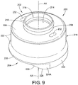
- FIGS. 9-12 an embodiment of a piston 200 suitable for use in forming a gas spring assembly according to the invention, such as gas spring assembly 102, for example, is illustrated that includes a first end 202 and an opposing second end 204.
- the first and second ends are longitudinally spaced from one another such that a central axis AX extends therebetween.
- First end 202 includes a first end wall 206 that is adapted to abuttingly engage an associated flexible wall or sleeve of a gas spring assembly (e.g., flexible sleeve 108 ).
- An axially-extending annular wall 208 can optionally project from along end wall 206 in a direction generally opposite second end 204 and can be dimensioned to cooperatively receive an open end (e.g., second end 146 ) of the flexible wall associated therewith.
- a radially outwardly-extending projection or lip 210 can optionally be included and can operate to at least partially maintain the open end of the flexible wall in abutting engagement with second end 202 of piston 200. It will be appreciate, however, that any other suitable arrangement and/or configuration could alternately be used for securing the flexible wall on or along piston 200.
- Piston 200 also includes a second end wall 212 that is disposed along second end 204 and is adapted to cooperatively engage an associated structural component (e.g., second structural component SSC in FIG. 3 ).
- second end wall 212 is approximately planar and is adapted to abuttingly engage an associated structural component for securement therealong.
- Piston 200 further includes an inner side wall 214 that extends circumferentially about axis AX and at least partially defines an inner cavity or chamber 216.
- inner side wall 214 extends in an approximately longitudinal direction and is generally disposed between first and second end walls 206 and 212.
- a plurality of inner support walls can optionally extend between different portions of inner side wall 214 and across inner cavity 216, such as has been discussed above with regard to inner support walls 172, for example.
- Piston 200 also includes an outer side wall 218 that extends in a generally longitudinal direction from along first end 202 toward second end 204 and is spaced radially-outwardly from inner side wall 214 such that an outer cavity 220 is formed therebetween.
- Outer side wall 218 includes a first side wall portion 222 that extends from along first end 202, such as from adjacent first end wall 206 thereof, for example, at a first axial distance or length LT1.
- first side wall portion 222 is fully circumferential and can extend substantially continuously about piston 200. As such, an associated flexible wall that is axially displaced along first side wall portion 222 will be fully supported along the entire length thereof.
- Outer side wall 218 also includes a plurality of second side wall portions 224 that extends from along first side wall portion 222 to a second axial distance or length LT2.
- the plurality of second side wall portions differ from the first side wall portion in that a plurality of second side wall portions 224 are not fully circumferential. That is, the plurality of second side wall portions extend only partially about the circumference of piston 200, such as along a circumferential section of first side wall portion 222, for example.
- outer side wall 218 has a bottom or distal edge 226 that has a non-planar profile that varies along the circumference of the piston.
- distal edge 226 (at a given diameter of outer side wall 218 ) do not fall within a common plane. While it will be appreciated that such a non-planar profile of distal edge 226 can take any suitable form and/or configuration, in one exemplary embodiment the portions of distal edge 226 established by first side wall portion 222 will fall within a first plane (not shown) and at least some portion of distal edge 226 established by at least one second side wall portion 224 will fall within a second plane (not shown) that is parallel with the first plane (not shown).
- a rolling lobe sleeve will, under certain conditions of operation and/or use, be displace beyond the distal edge of an outer side wall of the associated piston of a gas spring assembly.
- the provision of a plurality of second side wall portions 224 acts to extend the outer side wall beyond the area that is normally available to support the flexible sleeve of the gas spring assembly. In this way, such roll-off conditions can be minimized or eliminated, particularly in situations in which a gap or space is formed between the piston and the associated structural component, as discussed above.
- smooth transitions and gently curving surfaces are provide at, along and between the portions of distal edge 226 of outer side wall 218.
- Such smooth transitions and gently curving surfaces can minimize undesirable influences (e.g., stress concentrations) that may act on a flexible wall during contact therewith.
- undesirable influences e.g., stress concentrations
- the plurality of second side wall portions 224 is shown in FIGS. 9-12 as including optional transition sections 224A that extend from opposing ends of the second side wall portions.
- Transition sections 224A can act to interconnect the distal extent of the second side wall portions with the distal extent of the first side wall portion.
- distal edge 226 of outer side wall 218 can extend in a substantially continuous manner about the outer side wall.
- transition sections 224A can include one or more curvilinear edge portions and can be approximately tangentially interconnected with the distal extents of first and second side wall portions 222 and 224. As a result, distal edge 226 of outer side wall 218 can form a single contoured surface.
- any number of two or more second side wall portions 224 can be provided on or along piston 200, and that the two or more second side wall portions can be configured and/or arranged in any suitable manner and/or orientation.
- two second side wall portions 224 are included in forming side wall 218 of piston 200 in the embodiment shown in FIGS. 9-12 . These two second side wall portions are disposed circumferentially opposite one another (i.e., approximately 180 degrees apart) with each second side wall portion extending circumferentially through an angle AG1, as shown in FIG. 10 .
- second side wall portions can extend any suitable distance along the circumference of the piston, and such distance can be inclusive or exclusive of any optional transition sections (e.g., transition sections 224A ) that may be included.
- second side wall portions 224 can extend through an angle AG1 within a range of from approximately 10 degrees to approximately 170 degrees, and within a preferred range of from approximately 45 degrees to approximately 135 degrees, and within a more preferred range of from approximately 60 degrees to approximately 120 degrees.
- different ones of any two or more second side wall portions can optionally extend through different circumferential lengths and/or angles, rather than being substantially identical as illustrated in FIGS. 9-12 with respect to second side wall portions 224.
- outer side wall 218 and/or any portion or portions thereof can have any suitable size, shape, profile and/or configuration.
- the outer side wall and/or any portion or portions thereof can include sections that are curvilinear, frustoconical, cylindrical or any combination thereof in shape or profile.
- first side wall portion 222 includes a substantially cylindrical upper section 222A and a curvilinear lower section 222B, as indicated in FIG. 11 .
- second side wall portions 224 are shown as being substantially cylindrical. However, any other arrangement and/or configuration could alternately be used.
- Piston 200 also includes a plurality of outwardly-extending support walls 230 that extend between inner and outer side walls 214 and 218 and thereby structurally interconnect the same.
- outer support walls 230 can be of any suitable quantity, configuration and/or arrangement, and can extend along any portion of the longitudinal length of piston 200.
- outer support walls 230 extend radially-outwardly from inner side wall 214 and along approximately the entire longitudinal length of at least first side wall portion 222 of outer side wall 218 such that outer cavity 220 is separated into a plurality of individual chambers (not numbered).
- any other number, arrangement and/or configuration of inner and/or outer support walls could alternately be used.
- Piston 200 also includes at least one securement feature suitable for at least partially securing the piston on or along a corresponding structural component.
- piston 200 includes a plurality of passages 232 that extend through the piston and are suitable for receiving at least a portion of a fastener or other securement element for suitably affixing piston 200 on or along an associated structural component.
- any other suitable arrangement and/or configuration could alternately be used, such as one or more mounting studs (not shown) or threaded inserts (not shown), for example.
- Piston 200 can also optionally include at least one mounting feature adapted to cooperatively engage a corresponding mounting feature on an associated structural component such that the inter-engagement of the cooperative mounting features can act to withstand, overcome or otherwise accommodate laterally-acting loads or forces that may be applied to the piston, such as has been discussed above with regard to the inter-engagement of projection 116 and recess 118 in FIG. 3 , for example. That is, piston 200 can optionally include a recess 234 that is dimensioned to cooperatively receive an associated projection (e.g., projection 116 in FIG. 3 ) formed, installed or otherwise provided on or along an associated structural component with the recess and projection together forming a cooperative mounting arrangement, such as has been discussed above with regard to arrangement 114, for example.
- an associated projection e.g., projection 116 in FIG. 3
- any number of one or more recesses can be provided on piston 200.
- two recesses 234 are disposed circumferentially opposite one another (i.e., about 180 degrees apart).
- Such a configuration permits piston 200 to be positioned in either of two rotational orientations about axis AX, with circumferentially-opposing second side wall portions 224 disposed on each side of the associated structural component in either mounting position.
- any number of one or more cooperative mounting arrangements or portions thereof can be used (e.g., one projection with two or more cooperative recesses).
- any such one or more recesses can be provided on piston 200 in any suitable manner and using any suitable configuration and/or arrangement of structural elements and features to at least partially define the recess or recesses.
- recesses 234 are positioned between inner and outer side walls 214 and 218, respectively, such that forces and/or loads transferred to piston 200 by way of a recess are not directly applied to either of the inner or outer side walls, which is a preferred arrangement.
- an associated projection e.g., projection 116 in FIG. 3
- the one or more recesses can be established or otherwise defined through the inclusion of one or more recess walls that extend between adjacent ones of the outer support walls, which are identified in FIG. 10 by reference number 230A.
- the one or more recess walls that at least partially define the one or more optional recesses of the piston can be of any suitable size, shape, construction, configuration and/or arrangement.
- the recesses are at least partially defined by inner and outer recess walls 236 and 238, respectively.
- inner recess wall 236 extends in an approximately straight configuration and outer recess wall 238 is somewhat curved.
- piston 200 can optionally include one or more support walls or ribs extending between two of the recess walls and/or between one of the recess walls and another wall of the piston. It will be appreciated that such optional support ribs can act to buttress the recess walls and, thus, can result in a more robust recess that may be capable of increased performance (e.g., load carrying capacity).
- piston 200 optionally includes a plurality of recess support ribs 240 extending between inner and outer recess walls 236 and 238. Additionally, piston 200 is shown as including an optional inner support rib 242 extending between inner recess wall 236 and inner side wall 214.
- Piston 200 is also shown as optionally including a plurality of outer support ribs 244 extending between outer recess wall 238 and outer side wall 218. It is to be understood, however, that the arrangement of support ribs shown and described herein is merely exemplary and that any other arrangement, configuration and/or construction of support ribs could alternately be used.
- first end member and “second end member”
- numerical ordinals merely denote different singles of a plurality and do not imply any order or sequence unless specifically defined by the claim language.
- gas is used herein to broadly refer to any gaseous or vaporous fluid. Most commonly, air is used as the working medium of suspension systems and the components thereof, such as those described herein. However, it will be understood that any suitable gaseous fluid, such as nitrogen, could alternately be used.
Landscapes
- Engineering & Computer Science (AREA)
- Mechanical Engineering (AREA)
- General Engineering & Computer Science (AREA)
- Fluid-Damping Devices (AREA)
Description
- The subject matter of the present disclosure broadly relates to the art of gas spring devices and, more particularly, to a gas spring assembly according to the preamble of
claim 1. Examples of such gas spring assemblies are shown in documentsDE 101 49 057 A1 ,US 6 386 524 B1 and inDE 20 2005 007933 U1 . - A gas spring assembly comprising the characterizing part of
claim 1 is shown in the publishedpatent application EP 2 093 082 A1 , this document is only prior art under Article 54(3) EPC however. - The subject matter of the present disclosure finds particular application and use in conjunction with suspension systems of wheeled vehicles, and will be shown and described herein with particular reference thereto. However, it is to be appreciated that the present exemplary embodiments are also amenable to use in other applications and environments. For example, the subject matter of the present disclosure could be used in operative association with structural supports, height adjusting systems and/or actuators associated with industrial machinery, components thereof and/or other such equipment on which lateral load conditions may be encountered. Accordingly, the subject matter of the present disclosure is not intended to be limited to use associated with vehicle suspensions and it is to be understood that the embodiments shown and described herein are merely exemplary.
- Gas spring assemblies of various kinds and constructions are well known and commonly used in vehicle suspension systems, industrial machinery as well as other equipment and devices to provide dynamic load support between sprung and unsprung masses associated therewith. A typical gas spring assembly includes two opposing end members with a flexible wall or sleeve secured between the two end members that at least partially define a spring chamber. A quantity of pressurized gas, usually air, is contained within the spring chamber and acts on the spaced end members as well as opposing portions of the flexible wall to support the load of the sprung mass or a force that is otherwise applied to the gas spring assembly.
- It is commonly understood that gas spring assemblies are well suited for supporting loads acting axially (i.e., longitudinally between the opposed end members thereof), but that only a minimal lateral load, if any, can be supported by a typical gas spring assembly. Thus, applications that are normally identified as being well suited for the use of gas spring assemblies primarily involve the transfer of axially applied loads. As a result, there is a considerable body of art that is directed to arrangements for securing the gas spring assembly to a corresponding structural member in a way that provides sufficient axial support. Such arrangements commonly include the use of threaded fasteners, fixed mounting studs with threaded nuts and/or snap together-type connections.
- It has been recognized, however, that in some applications the action of the gas spring assembly itself can generate lateral load conditions on one or more of the end members thereof. For example, in an application in which one end member is disposed at and/or moved through an angle relative to the other end member, the flexible wall is urged outwardly toward the open end of the included angle between the end members. This action can generate a lateral load acting on one or both of the end members. Unfortunately, many known securement arrangements, having been designed to withstand axially-applied loads, as discussed above, are less well suited for use under lateral or shear loads. Therefore, a need exists for an improved arrangement for engaging an end member of a gas spring assembly with a corresponding structural member such that the interface can withstand the aforementioned lateral load conditions, such as may be encountered by a vehicle suspension system, for example.
- Various arrangements have been proposed to overcome the above-described difficulties. One example of such an arrangement is shown in
U.S. Patent No. 5,342,139 , which discloses an attachment device for mounting an end member of an air spring assembly on a corresponding support component. Another example of such an arrangement is shown inU.S. Patent No. 6,752,407 , which discloses a multi-component and mounting plate arrangement for securing an air spring along a structural component. Still another example of such an arrangement is shown inU.S. Patent No. 6,945,548 , which discloses a spacer that is adapted to engage the air spring assembly and includes a winged portion that engages a slot in the corresponding structural component. Yet another example of such an arrangement is shown inU.S. Patent Application Publication No. 2006/0055094 , which discloses an air spring with end members having snap-in attachments for engaging the corresponding structural members. - While the above-described arrangements have met with some degree of success, numerous difficulties and/or disadvantages have been identified with the same, which have undesirably impacted the widespread adoption and use of the same. Such difficulties and/or disadvantages include the use of additional components, such as extra fasteners, retention pins, mounting brackets and/or other components, which undesirably increase inventory and production costs and can also raise installation and maintenance issues. What's more, certain design configurations, such as snap-in type designs, for example, may be insufficiently robust to withstand both the axial and lateral load conditions, particularly those associated with heavy-duty applications. Furthermore, some known arrangements utilize features that extend radially-outwardly beyond the periphery of at least a portion of the gas spring assembly, which can result in space constraints for other components.
- Additionally, attachment and/or other features of suspension components of vehicles are often disposed within approximately the same area in which a gas spring assembly of a suspension system also resides. As such, accommodations are often provided on one or more components of gas spring assemblies to help avoid interference with the attachment and/or other features while permitting the component of the gas spring assembly to be mounted or otherwise secured to a suspension component in that same area.
- Such accommodations are commonly used in association with gas spring assemblies of the rolling lobe-type, which typically include a piston that has an outer side wall and flexible sleeve that is secured along the piston such that a lobe formed thereby can roll along the outer side wall as the gas spring assembly undergoes displacement. As one example of such an accommodation, the outer side wall of the piston can be supported or otherwise disposed in vertically spaced relation to the associated structural component along which the piston is secured. This accommodation can be accomplished in any suitable manner. For example, the piston of the gas spring assembly can include a bottom or end wall that the abuttingly engages the associated structural component with the nearest end of the outer side wall being disposed in spaced relation to the bottom wall. As another example, a spacer or other suitable component can be positioned and secured between the piston of the gas spring assembly and the associated structural component to space the end of the outer side wall a distance from the associated structural component.
- In any case, such an accommodation often results in a gap or space being formed between the end of the outer side wall of the piston and the associated structural component to which the gas spring assembly is mounted. Under certain circumstances and conditions of operation of the gas spring assembly, the lobe of the flexible sleeve can begin to roll off of the edge of the outer side wall and into the aforementioned gap or space. Such situations are generally undesirable, as the same can result in decreased performance (e.g., a reduction in spring rate) of the gas spring assembly. Additionally, it has been recognized that as the gap or space increases in size, even greater decreases in performance can occur.
- Therefore, it is believed desirable to develop a gas spring assembly that overcomes the foregoing and other issues and disadvantages.
- A gas spring assembly in accordance with the subject matter of the present invention is defined in
claim 1. - Additionally, a gas spring assembly according to the foregoing paragraph can be provided with the features of the dependent claims.
-
-
FIG. 1 is a schematic representation of a vehicle that includes gas spring assemblies operatively connected to vehicle structures using cooperative mounting arrangements in accordance with the subject matter of the present disclosure. -
FIG. 2 is a side view of the vehicle inFIG. 1 taken from along line 2-2 thereof. -
FIG. 3 is an enlarged portion of the side view inFIG. 2 showing in greater detail a gas spring assembly including an exemplary mounting arrangement for cooperative use with an associated vehicle structure. -
FIG. 4 is top perspective view of an exemplary end member of the gas spring assembly inFIG. 3 . -
FIG. 5 is a bottom perspective view of the exemplary end member inFIG. 4 . -
FIG. 6 is a bottom plan view of the exemplary end member inFIGS. 4 and5 . -
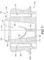
FIG. 7 is a cross-sectional side view of the exemplary end member inFIGS. 4-6 taken from along line 7-7 inFIG. 6 . -
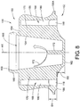
FIG. 8 is a cross-sectional side view of the exemplary end member inFIGS. 4-7 taken from along line 8-8 inFIG. 6 . -
FIG. 9 is a top perspective view of an end member in accordance with the invention of the gas spring assembly inFIG. 3 . -
FIG. 10 is a bottom perspective view of the end member inFIG. 9 . -
FIG. 11 is a side view of the end member inFIGS. 9 and10 taken from along line 11-11 inFIG. 9 . -
FIG. 12 is a side view of the end member inFIGS. 9-11 taken from along line 12-12 inFIG. 11 . - Turning now to the drawings, wherein the showings are for the purpose of illustrating examples of the subject matter of the present disclosure and which are not intended as a limitation of the same,
FIG. 1 illustrates asuspension system 100 disposed between a sprung mass, such as an associated vehicle body BDY, for example, and an unsprung mass, such as an associated wheel WHL or an associated wheel-engaging member WEM, for example, of an associated vehicle VHC. It will be appreciated that any such suspension system can include any number of one or more systems, components and/or devices and that the same can be operatively connected between the sprung and unsprung masses of the associated vehicle in any suitable manner. For example, such a suspension system can include a plurality of damping members (not shown), which can be operatively connected between the sprung and unsprung masses of the associated vehicle in any suitable manner. - Additionally, or in the alternative, such a suspension system can include a plurality of gas spring assemblies that are supported between the sprung and unsprung masses of associated vehicle VHC. In the example shown in
FIG. 1 ,suspension system 100 includes sixgas spring assemblies 102, one or more of which is disposed toward each corner of the associated vehicle adjacent a corresponding wheel WHL thereof. However, it will be appreciated that any other suitable number ofgas spring assemblies 102 could alternately be used and that such gas spring assemblies can be disposed in any other suitable configuration or arrangement. - As will be shown and discussed in greater detail hereinafter,
gas spring assemblies 102 include a first or upper end member, such as abead plate 104, for example, a second or lower end member, such aspiston 106, for example, and a flexible wall, such as anelongated sleeve 108, for example, that is secured therebetween in a substantially fluid-tight manner. Thus, it will be recognized that the gas spring assemblies shown and described herein (e.g., gas spring assemblies 102) are of a rolling lobe-type construction. - Furthermore, it will be appreciated that the gas spring assemblies can be operatively connected between the sprung and unsprung masses of an associated vehicle in any suitable manner. For example,
gas spring assemblies 102 are shown inFIG. 2 as being operatively connected between wheel-engaging members WEM and body BDY of associated vehicle VHC. It will be appreciated, however, that the configuration of vehicle VHC inFIG. 2 is merely a schematic representation of the structural components of the sprung and unsprung masses of the vehicle. Thus, it will be understood that this schematic representation is provided for purposes of discussion and ease of understanding and is not intended to be in any way limiting. - With further reference to the exemplary arrangement in
FIG. 2 , wheel-engaging members WEM are shown as being pivotally attached to structural components STL such that the wheel-engaging members move through an angle AG1 relative to body BDY as wheels WHL undergo vertical movements (e.g., jounce and rebound actions), which movements are represented inFIG. 2 by arrow AR1. Thus, it will be recognized that as wheels WHL move vertically away from body BDY (i.e., under a rebound condition), angle AG1 between the body and the corresponding wheel-engaging member will increase andgas spring assembly 102, which is operatively connected therebetween, will become elongated. It will also be recognized that as wheels WHL move vertically toward body BDY (i.e., under a jounce condition), angle AG1 will decrease andgas spring assembly 102 will become compressed. Due, at least in part, to the body and wheel-engaging member acting on the gas spring assembly at an angle to one another,gas spring assembly 102 will normally be pinched, squeezed or otherwise biased toward the open end of angle AG1, as is represented by arrow AR2. This biasing action results in the generation of forces that act laterally on the opposing end members of the gas spring assembly (e.g.,bead plate 104 and piston 106), as is indicated by arrows AR3 and AR4, respectively, inFIG. 2 . Thus, the biasing action acts to urge the end members of the gas spring assembly in a laterally-outward direction, such as toward wheels WHL, for example. - It is common practice for gas spring assemblies to be secured to the associated sprung and unsprung masses in a manner suitable for withstanding longitudinally (i.e., axially) acting forces or loads. Additionally, it will be appreciated that securement components and/or features of a wide variety of types, kinds, configurations and/or constructions have been used to secure the end members of the gas spring assemblies to the vehicle components in the longitudinal (i.e., axial) direction. In many such known mounting arrangements, one or more fasteners or other securement elements will pass through an opening in the structural component on which the end member is supported to engage the end member and thereby secure the gas spring assembly to the structural component.
- In other situations, however, it is desirable to secure the gas spring assembly to the structural component without the use of fasteners or other securement elements that extend through (i.e., pass through an opening in) the structural component. Such external mounting or clamping arrangements may be employed for any one or more of a variety of reasons, such as space constraints and/or strength-related issues, for example. While it will be appreciated that any suitable external mounting or clamping arrangement may be used, one example of such an arrangement is shown and described in
U.S. Patent No. 6,945,548 , which illustrates an air spring bracket (702) in FIG. 19 thereof and which is described therein at least column 14 from about lines 23-47. A similar arrangement is shown inFIGS. 2 and3 of the present disclosure that includes anexemplary bracket 110 extending around three sides of wheel-engaging member WEM withpiston 106 being secured thereto by way of fasteners 112 (only one of which is shown) thatinterconnect bracket 110 andpiston 106 to thereby secure the gas spring assembly on or along the structural component (e.g., wheel-engaging member WEM). - In accordance with one aspect of the subject disclosure, a cooperative mounting arrangement is provided in which an end member of a gas spring assembly and a corresponding vehicle component associated therewith interengage one another. In this way, the aforementioned laterally-acting forces associated with the pinching action can be transferred from the end member to the corresponding structural component without undesirably effecting the gas spring assembly. And, it will be appreciated that a cooperative mounting arrangement in accordance with the subject matter of the present disclosure may find particular application and use in connection with external mounting or clamping arrangements that extend along the exterior of the wheel-engaging member (or other vehicle component) and are secured thereto without the use of elements (e.g., a fastener or other securement device) that extend through the wheel-engaging member (or other vehicle component).
- It will be appreciated that any suitable configuration can be used to secure the opposing end members of the gas spring assembly to the vehicle components and thereby accommodate any laterally-extending forces urging the end members toward the open end of angle AG1, as discussed above. As one example, a
cooperative mounting arrangement 114 can include a projection 116 (FIG. 3 ) extending from wheel-engaging member WEM and a recess or pocket 118 (FIG. 3 ) formed into an end member, such aspiston 106, for example, of the gas spring assembly or another component operatively associated therewith, such as a spacer, for example. Such a cooperative mounting arrangement permits the end member of the gas spring assembly and the wheel-engaging member (or other vehicle component) to interengage one another and thereby maintain the position of the end member relative to the wheel-engaging member (or other vehicle component) under any laterally acting forces, such as may be generated by the above-discussed compressing or pinching action of the vehicle components, for example. -
Suspension system 100 can also optionally include a pressurizedgas supply system 120 that is operatively associated with the gas spring assemblies for selectively supplying pressurized gas (e.g., air) thereto and selectively transferring pressurized gas therefrom. In the exemplary embodiment shown inFIG. 1 ,gas supply system 120 includes a pressurized gas source, such as acompressor 122, for example, for generating pressurized air or other gases. The gas supply system can also include any number of one or more control devices of any suitable type, kind and/or construction that may be capable of affecting the selective transfer of pressurized gas. For example, avalve assembly 124 is shown as being in communication withcompressor 122 and can be of any suitable configuration or arrangement. In the exemplary embodiment shown,valve assembly 124 includes avalve block 126 with a plurality ofvalves 128 supported thereon.Valve assembly 124 can also optionally include a suitable exhaust, such as amuffler 130, for example, for venting pressurized gas from the system. Optionally, pressurizedgas supply system 120 can also include areservoir 132 in fluid communication withvalve assembly 124 and suitable for storing pressurized gas. - The one or more control devices, such as
valve assembly 124, for example, can be in communication withgas spring assemblies 102 in any suitable manner, such as, for example, through suitablefluid transmission lines 134. As such, pressurized gas can be selectively transmitted to and/or from the gas springs throughvalve assembly 124, such as to alter or maintain vehicle height at one or more corners of the vehicle, for example. -
Suspension system 100 also includes acontrol system 136 that is capable of communication with any one or more other systems and/or components (not shown) ofsuspension system 100 and/or of which VHC and is capable of selective operation and control of the suspension system.Control system 136 includes a controller or electronic control unit (ECU) 138 in communication withcompressor 122 and/orvalve assembly 124, such as through a suitable conductor or lead (not shown), for example, for selective operation and control thereof, including supplying and exhausting pressurized fluid to and fromgas spring assemblies 102. Additionally, it will be appreciated thatcontroller 138 can be of any suitable type, kind and/or configuration. -
Control system 136 can also optionally include one or more height or distance sensing devices (not shown) as well as any other desired systems and/or components. Such height sensors, if provided, are preferably capable of generating or otherwise outputting a signal having a relation to a height or distance, such as between spaced components of the vehicle, for example. It will be appreciated that any such optional height sensors or any other distance-determining devices, if provided, can be of any suitable type, kind, construction and/or configuration, such as mechanical linkage sensors, ultrasonic wave sensors or electromagnetic wave sensors, such as may operate using ultrasonic or electromagnetic waves, for example. - Turning now to
FIG. 3 ,gas spring assembly 102 includes a central axis AX that extends longitudinally between the first end member (e.g., bead plate 104), which is disposed toward one end of axis AX, and the opposing second end member (e.g., piston 106), which is spaced from the first end member toward another end of axis AX. The first end member is disposed along a first or upper structural component FSC, such as a vehicle body or chassis, for example, and can be adapted for securement thereto in any suitable manner. For example, first structural component FSC is shown inFIG. 3 as including holes or openings OPN that are suitable for securement of the first end member to the first structural component.Gas spring assembly 102 is shown as including mountingstuds 140 that project axially-outwardly frombead plate 104 and extend through openings OPN in the first structural component. Suitable fastening elements, such as threaded nuts (not shown), for example, can be used to securebead plate 104 to first structural component FSC. It will be recognized that such a mounting arrangement will generally be sufficient to oppose any lateral loads or forces acting on the first end member (e.g., bead plate 104), such as the lateral forces represented by arrow AR3 inFIG. 2 , for example. - The second end member is disposed along a second or lower structural component SSC, such as an axle or other wheel-engaging member, for example, and is adapted for securement on or along this second structural component. In one preferred arrangement, the second end member is adapted for securement to the second structural component by way of an external mounting bracket or other component or arrangement that does not rely upon the use of fasteners extending through the second structural component. One example of such an external mounting arrangement is shown in
FIGS. 2 and3 asbracket 110 andfasteners 112. However, it will be appreciated that any other suitable arrangement could alternately be used. - Additionally, at least one of the end members of a gas spring assembly and a corresponding one of the structural components associated therewith include a cooperative mounting arrangement (e.g., cooperative mounting arrangement 114) suitable for accommodating laterally-acting forces, such as have been previously described, for example. In one preferred arrangement, such a cooperative mounting arrangement will be used in cases in which an external mounting bracket or other arrangement is employed that does not rely upon the use of fasteners that extend through openings in the associated structural component, such as the external mounting arrangement in
FIGS. 2 and3 usingbracket 110 andfasteners 112, for example. It will be appreciated that the use of such a cooperative mounting arrangement can act to oppose any such laterally-acting forces, which may not be sufficiently accommodated by an external mounting arrangement acting alone. - As mentioned above, the opposing end members (e.g.,
bead plate 104 and piston 106) can be secured to the flexible wall (e.g., flexible sleeve 108) in any manner suitable for forming a substantially fluid-tight seal therewith such that aspring chamber 142 is at least partially defined therebetween. As one example, the flexible wall (e.g., flexible sleeve 108) is shown and described herein as being of an elongated sleeve-type configuration that is capable of forming a rolling lobe along the exterior of an end member (e.g., piston 104) of the gas spring assembly. However, it is to be understood that the subject matter of the present disclosure is capable of broad use in association with any suitable type, kind, and/or configuration of gas spring assembly. - Also, the flexible wall (e.g., flexible sleeve 108) can be secured between the first and second end members in any suitable manner. As shown in
FIGS 2 and3 , for example,flexible sleeve 108 extends between opposing ends 144 and 146.End 144 is shown as being an open end that is connected alongbead plate 104 using a crimped arrangement to form a substantially fluid tight seal between the bead plate and the end of the flexible sleeve.End 146 of the flexible sleeve is received on a portion ofpiston 106 and is secured thereon by way of a snap-fit connection. Pressurized gas can be communicated into and out ofspring chamber 142 in any suitable manner, such as, for example, through apassage 148 extending through one of mountingstuds 140. - With reference, now, to
FIGS. 3-8 ,exemplary piston 106, not in accordance with the invention, extends axially between opposing first and second ends, which are generally represented byreference numbers First end 150 includes afirst end wall 154 that is adapted to abuttingly engageflexible sleeve 108 and anouter side wall 156 that extends from alongend wall 154 towardsecond end 152 of the piston.Outer side wall 156 is shown as having a curvilinear shape or configuration. However, it will be appreciated that any suitable size, shape and/or configuration could alternately be used, such as a frustoconical or a cylindrical shape, for example. In any case,outer side wall 156 will include a radially-outermost side wall portion that at least partially defines the outermost radial extent of the piston. In the exemplary embodiment shown inFIGS. 3-8 , this radially-outmost side wall portion is identified byreference number 156A and will have an overall dimension (not shown) representing the maximum diameter or width of the radially-outermost side wall portion. An axially-extendingannular wall 158 projects from alongend wall 154 generally opposite the direction ofouter side wall 156 and can be dimensioned to cooperatively receive an open end (e.g., second end 146) of the flexible wall associated therewith. A radially outwardly-extending projection orlip 160 is shown as being disposed alongannular wall 158 and can operate to at least partially maintainsecond end 146 onannular wall 158. It will be appreciated, however, that any suitable configuration and/or arrangement can alternately be used for securement of the flexible wall on or along the piston and, thus, thatannular wall 158 andlip 160 are optional. -
Piston 106 also includes asecond end wall 162 that is disposed alongsecond end 152 and adapted to cooperatively engage second structural component SSC. In the exemplary case shown,second end wall 162 is approximately planar and adapted to abuttingly engage second structural component SSC.Piston 106 further includes aninner side wall 164 that at least partially defines aninner cavity 166. In the exemplary arrangement shown,inner side wall 164 extends in an approximately longitudinal direction and generally between first andsecond end walls Inner side wall 164 is disposed in radially inwardly-spaced relation toouter side wall 156 such that anouter cavity 168 is formed therebetween. A plurality of outwardly-extendingsupport walls 170 extend between the inner and outer side walls and thereby structurally interconnect the same. Additionally, a plurality ofinner support walls 172 can optionally be included withininner cavity 166, such as, for example, alongsecond end wall 162 and extending generally between different portions ofinner side wall 164.Support walls 170 can be of any suitable quantity, configuration and/or arrangement and can extend along any portion of the longitudinal length ofpiston 106. In one exemplary case,outer support walls 170 extend radially-outwardly frominner side wall 164 and along approximately the entire longitudinal length ofouter side wall 156 such thatouter cavity 168 is separated into a plurality of individual chambers (not numbered). However, it will be understood that any other number, arrangement and/or configuration ofinner support walls 172 and/orouter support walls 170 can alternately be used. -
Piston 106 also includes at least one securement feature suitable for at least partially securing the piston on or along the corresponding structural component. In the exemplary arrangement shown,piston 106 includes a plurality ofpassages 174 that extend through the piston and are suitable for receiving at least a portion of a fastener, such asfastener 112, for example. Mating fastener components, such as threaded nuts (not shown), for example, could be received within a portion ofpassages 174 or, alternately, mating threads (not shown) could be provided within the passage, either directly in the piston material or in the form of threaded inserts (not shown) embedded within the piston. It will be appreciated, however, that any other suitable arrangement could alternately be used, such as the use of mounting studs (not shown) projecting from the piston, for example. - As discussed above,
piston 106 includes at least one mounting feature adapted to cooperatively engage a corresponding mounting feature on an associated structural component such that the interengagement of the cooperative mounting features can act to withstand, overcome or otherwise accommodate laterally-acting loads or forces that may be applied to the piston. As is further illustrated inFIGS. 5 and6 ,piston 106 includes arecess 118 dimensioned to cooperatively receive a corresponding projection 116 (FIG. 3 ) formed, installed or otherwise provided on or along second structural component SSC with the recess and projection together forming cooperative mountingarrangement 114. Additionally, any number of one or more recesses, such asrecesses 118, for example, can be used. As illustrated in the accompanying drawing figures, two recess disposed circumferentially opposite one another (i.e., about 180 degrees apart) are provided onpiston 106 and permit the same to be mounted in either of two rotational orientations. However, it is to be understood that any number of one or more cooperative mounting arrangements or portions thereof can be used (e.g., one projection with two or more cooperative recesses). -
Recesses 118 can be provided onpiston 106 in any suitable manner and using any suitable configuration and/or arrangement of structural elements and features to at least partially define the recess. In the exemplary arrangement shown,recess 118 is positioned in between outer andinner side walls piston 106 by way of the recess are not directly applied to either of the inner or outer side walls, which is a preferred arrangement. Thus, in such a preferred arrangement,projection 116 will not directly abuttingly engage either of the inner side wall or the outer side wall. Rather, recess 118 can be established by one or more recess walls extending between adjacent ones of the outer support walls, which are identified inFIGS. 5 and6 byreference numbers 170A. It will be appreciated that the one or more recess walls that at least partially define the one or more recesses of the end member can be of any suitable size, shape, construction, configuration and/or arrangement. In the exemplary arrangement shown, the recesses are at least partially defined by inner andouter recess walls - A piston not in accordance with the subject matter of the present invention (e.g., piston 106) can optionally include one or more support walls or ribs extending between two of the recess walls and/or between one of the recess walls and another wall of the piston. It will be appreciated that such optional support ribs can act to buttress the recess walls and, thus, can result in a more robust recess that may be capable of increased performance (e.g., load carrying capacity). In the present exemplary arrangement,
piston 106 includes a plurality ofrecess support ribs 180 extending between inner andouter recess walls piston 106 is shown as including aninner support rib 182 extending betweeninner recess wall 176 andinner side wall 164.Piston 106 is also shown as including a plurality ofouter support ribs 184 extending betweenouter recess wall 178 andouter side wall 156. It is to be understood, however, that the arrangement of support ribs shown and described herein is merely exemplary and that any other number, arrangement, configuration and/or construction of support ribs can alternately be used. - The example in
FIGS. 2-8 includes an arrangement in which a component (e.g., piston 106) of a gas spring assembly is supported directly on an associated structural component (e.g., second structural component SSC). It will be recognized, however, that in some cases it may be desirable for a gas spring assembly to be supported in spaced relation to an associated structural component. In such cases, a spacer may be used that is secured between an end member of the gas spring assembly and the associated structural component. One example of a known spacer is shown and described inU.S. Patent No. 6,945,548 , as has been discussed above. - Turning now to
FIGS. 9-12 , an embodiment of apiston 200 suitable for use in forming a gas spring assembly according to the invention, such asgas spring assembly 102, for example, is illustrated that includes afirst end 202 and an opposingsecond end 204. The first and second ends are longitudinally spaced from one another such that a central axis AX extends therebetween.First end 202 includes afirst end wall 206 that is adapted to abuttingly engage an associated flexible wall or sleeve of a gas spring assembly (e.g., flexible sleeve 108). An axially-extendingannular wall 208 can optionally project from alongend wall 206 in a direction generally oppositesecond end 204 and can be dimensioned to cooperatively receive an open end (e.g., second end 146) of the flexible wall associated therewith. A radially outwardly-extending projection orlip 210 can optionally be included and can operate to at least partially maintain the open end of the flexible wall in abutting engagement withsecond end 202 ofpiston 200. It will be appreciate, however, that any other suitable arrangement and/or configuration could alternately be used for securing the flexible wall on or alongpiston 200. -
Piston 200 also includes asecond end wall 212 that is disposed alongsecond end 204 and is adapted to cooperatively engage an associated structural component (e.g., second structural component SSC inFIG. 3 ). In the exemplary arrangement shown inFIGS. 9-12 ,second end wall 212 is approximately planar and is adapted to abuttingly engage an associated structural component for securement therealong.Piston 200 further includes aninner side wall 214 that extends circumferentially about axis AX and at least partially defines an inner cavity orchamber 216. In the exemplary arrangement shown,inner side wall 214 extends in an approximately longitudinal direction and is generally disposed between first andsecond end walls inner side wall 214 and acrossinner cavity 216, such as has been discussed above with regard toinner support walls 172, for example. -
Piston 200 also includes anouter side wall 218 that extends in a generally longitudinal direction from alongfirst end 202 towardsecond end 204 and is spaced radially-outwardly frominner side wall 214 such that anouter cavity 220 is formed therebetween.Outer side wall 218 includes a firstside wall portion 222 that extends from alongfirst end 202, such as from adjacentfirst end wall 206 thereof, for example, at a first axial distance or length LT1. Along this first length, firstside wall portion 222 is fully circumferential and can extend substantially continuously aboutpiston 200. As such, an associated flexible wall that is axially displaced along firstside wall portion 222 will be fully supported along the entire length thereof. -
Outer side wall 218 also includes a plurality of secondside wall portions 224 that extends from along firstside wall portion 222 to a second axial distance or length LT2. In addition to varying in length, the plurality of second side wall portions differ from the first side wall portion in that a plurality of secondside wall portions 224 are not fully circumferential. That is, the plurality of second side wall portions extend only partially about the circumference ofpiston 200, such as along a circumferential section of firstside wall portion 222, for example. As a result,outer side wall 218 has a bottom ordistal edge 226 that has a non-planar profile that varies along the circumference of the piston. That is, all circumferential portions of distal edge 226 (at a given diameter of outer side wall 218) do not fall within a common plane. While it will be appreciated that such a non-planar profile ofdistal edge 226 can take any suitable form and/or configuration, in one exemplary embodiment the portions ofdistal edge 226 established by firstside wall portion 222 will fall within a first plane (not shown) and at least some portion ofdistal edge 226 established by at least one secondside wall portion 224 will fall within a second plane (not shown) that is parallel with the first plane (not shown). - As discussed above, a rolling lobe sleeve will, under certain conditions of operation and/or use, be displace beyond the distal edge of an outer side wall of the associated piston of a gas spring assembly. The provision of a plurality of second
side wall portions 224 acts to extend the outer side wall beyond the area that is normally available to support the flexible sleeve of the gas spring assembly. In this way, such roll-off conditions can be minimized or eliminated, particularly in situations in which a gap or space is formed between the piston and the associated structural component, as discussed above. - It will be recognized, however, that because the second side wall portions do not extend around the full circumference of the piston, at least some portion of the flexible sleeve may remain unsupported and, thus, even partially roll-off a section of the distal edge of the piston. As such, in one exemplary embodiment, smooth transitions and gently curving surfaces are provide at, along and between the portions of
distal edge 226 ofouter side wall 218. Such smooth transitions and gently curving surfaces can minimize undesirable influences (e.g., stress concentrations) that may act on a flexible wall during contact therewith. Such a situation may occur where the rolling lobe of a flexible sleeve is longitudinally displaced from along firstside wall portion 222 onto and off of the plurality of secondside wall portions 224, such as has been discussed above, for example. - As such, the plurality of second
side wall portions 224 is shown inFIGS. 9-12 as includingoptional transition sections 224A that extend from opposing ends of the second side wall portions.Transition sections 224A, if provided, can act to interconnect the distal extent of the second side wall portions with the distal extent of the first side wall portion. In this manner,distal edge 226 ofouter side wall 218 can extend in a substantially continuous manner about the outer side wall. In one preferred embodiment,transition sections 224A can include one or more curvilinear edge portions and can be approximately tangentially interconnected with the distal extents of first and secondside wall portions distal edge 226 ofouter side wall 218 can form a single contoured surface. - It will be appreciated that any number of two or more second
side wall portions 224 can be provided on or alongpiston 200, and that the two or more second side wall portions can be configured and/or arranged in any suitable manner and/or orientation. For example, two secondside wall portions 224 are included in formingside wall 218 ofpiston 200 in the embodiment shown inFIGS. 9-12 . These two second side wall portions are disposed circumferentially opposite one another (i.e., approximately 180 degrees apart) with each second side wall portion extending circumferentially through an angle AG1, as shown inFIG. 10 . - Additionally, it will be appreciated that the plurality of second side wall portions can extend any suitable distance along the circumference of the piston, and such distance can be inclusive or exclusive of any optional transition sections (e.g.,
transition sections 224A) that may be included. For example, secondside wall portions 224 can extend through an angle AG1 within a range of from approximately 10 degrees to approximately 170 degrees, and within a preferred range of from approximately 45 degrees to approximately 135 degrees, and within a more preferred range of from approximately 60 degrees to approximately 120 degrees. Furthermore, different ones of any two or more second side wall portions, can optionally extend through different circumferential lengths and/or angles, rather than being substantially identical as illustrated inFIGS. 9-12 with respect to secondside wall portions 224. - Furthermore, it will be appreciated that
outer side wall 218 and/or any portion or portions thereof, can have any suitable size, shape, profile and/or configuration. For example, the outer side wall and/or any portion or portions thereof can include sections that are curvilinear, frustoconical, cylindrical or any combination thereof in shape or profile. As shown inFIGS. 9-12 , firstside wall portion 222 includes a substantially cylindricalupper section 222A and a curvilinearlower section 222B, as indicated inFIG. 11 . Additionally, secondside wall portions 224 are shown as being substantially cylindrical. However, any other arrangement and/or configuration could alternately be used. -
Piston 200 also includes a plurality of outwardly-extendingsupport walls 230 that extend between inner andouter side walls outer support walls 230 can be of any suitable quantity, configuration and/or arrangement, and can extend along any portion of the longitudinal length ofpiston 200. In one exemplary case,outer support walls 230 extend radially-outwardly frominner side wall 214 and along approximately the entire longitudinal length of at least firstside wall portion 222 ofouter side wall 218 such thatouter cavity 220 is separated into a plurality of individual chambers (not numbered). However, it will be understood that any other number, arrangement and/or configuration of inner and/or outer support walls could alternately be used. -
Piston 200 also includes at least one securement feature suitable for at least partially securing the piston on or along a corresponding structural component. In the exemplary arrangement shown,piston 200 includes a plurality ofpassages 232 that extend through the piston and are suitable for receiving at least a portion of a fastener or other securement element for suitably affixingpiston 200 on or along an associated structural component. It will be appreciated, however, that any other suitable arrangement and/or configuration could alternately be used, such as one or more mounting studs (not shown) or threaded inserts (not shown), for example. -
Piston 200 can also optionally include at least one mounting feature adapted to cooperatively engage a corresponding mounting feature on an associated structural component such that the inter-engagement of the cooperative mounting features can act to withstand, overcome or otherwise accommodate laterally-acting loads or forces that may be applied to the piston, such as has been discussed above with regard to the inter-engagement ofprojection 116 andrecess 118 inFIG. 3 , for example. That is,piston 200 can optionally include arecess 234 that is dimensioned to cooperatively receive an associated projection (e.g.,projection 116 inFIG. 3 ) formed, installed or otherwise provided on or along an associated structural component with the recess and projection together forming a cooperative mounting arrangement, such as has been discussed above with regard toarrangement 114, for example. - It will be appreciated that any number of one or more recesses, such as
recesses 234, for example, can be provided onpiston 200. As illustrated inFIG. 10 , tworecesses 234 are disposed circumferentially opposite one another (i.e., about 180 degrees apart). Such a configuration permitspiston 200 to be positioned in either of two rotational orientations about axis AX, with circumferentially-opposing secondside wall portions 224 disposed on each side of the associated structural component in either mounting position. Nonetheless, it is to be understood that any number of one or more cooperative mounting arrangements or portions thereof can be used (e.g., one projection with two or more cooperative recesses). - Additionally, any such one or more recesses, if included, can be provided on
piston 200 in any suitable manner and using any suitable configuration and/or arrangement of structural elements and features to at least partially define the recess or recesses. In the exemplary arrangement shown, recesses 234 are positioned between inner andouter side walls piston 200 by way of a recess are not directly applied to either of the inner or outer side walls, which is a preferred arrangement. Thus, in such a preferred arrangement, an associated projection (e.g.,projection 116 inFIG. 3 ) will not directly abuttingly engage either of the inner side wall or the outer side wall of the piston. Rather, the one or more recesses can be established or otherwise defined through the inclusion of one or more recess walls that extend between adjacent ones of the outer support walls, which are identified inFIG. 10 byreference number 230A. It will be appreciated that the one or more recess walls that at least partially define the one or more optional recesses of the piston can be of any suitable size, shape, construction, configuration and/or arrangement. In the arrangement shown, the recesses are at least partially defined by inner andouter recess walls inner recess wall 236 extends in an approximately straight configuration andouter recess wall 238 is somewhat curved. - Additionally,
piston 200 can optionally include one or more support walls or ribs extending between two of the recess walls and/or between one of the recess walls and another wall of the piston. It will be appreciated that such optional support ribs can act to buttress the recess walls and, thus, can result in a more robust recess that may be capable of increased performance (e.g., load carrying capacity). In the present exemplary arrangement,piston 200 optionally includes a plurality ofrecess support ribs 240 extending between inner andouter recess walls piston 200 is shown as including an optionalinner support rib 242 extending betweeninner recess wall 236 andinner side wall 214.Piston 200 is also shown as optionally including a plurality ofouter support ribs 244 extending betweenouter recess wall 238 andouter side wall 218. It is to be understood, however, that the arrangement of support ribs shown and described herein is merely exemplary and that any other arrangement, configuration and/or construction of support ribs could alternately be used. - As used herein with reference to certain elements, components and/or structures (e.g., "first end member" and "second end member"), numerical ordinals merely denote different singles of a plurality and do not imply any order or sequence unless specifically defined by the claim language. Additionally, the term "gas" is used herein to broadly refer to any gaseous or vaporous fluid. Most commonly, air is used as the working medium of suspension systems and the components thereof, such as those described herein. However, it will be understood that any suitable gaseous fluid, such as nitrogen, could alternately be used.
Claims (13)
- A gas spring assembly (102) comprising:a flexible sleeve (108) including a sleeve wall extending between longitudinally-spaced sleeve ends (144, 146) and having a longitudinal axis (AX) extending therebetween, said sleeve wall extending circumferentially about said axis to at least partially define a spring chamber (142);an end member (104) secured along one of said ends (144) of said flexible sleeve (108) such that a substantially fluid-tight seal is formed with said sleeve wall; anda gas spring piston (200) secured on the other of said ends (146) of said flexible sleeve (108) such that a substantially fluid-tight seal is formed with said sleeve wall, said gas spring piston (200) comprising:a first end wall (206) abuttingly engaging said flexible sleeve (108);an outer side wall (218) extending longitudinally from along said first end wall (206), said outer side wall suitable for rolling a lobe of said flexible sleeve (108) therealong, said outer side wall (218) including a first side wall portion (222) at least partially defining a fully circumferential support area for abuttingly engaging said flexible sleeve (108), and said outer side wall (218) extending longitudinally from said first side wall portion (222) in a direction away from said first end wall (206);an inner side wall (214) disposed in radially-inwardly spaced relation to said outer side wall (218) such that an outer chamber (220) is at least partially defined therebetween;a plurality of support walls (230) extending outwardly between said inner side wall (214) and said outer side wall (218); anda second end wall (212) adapted to engage an associated structural component (SSC),characterized in thatsaid outer side wall (218) includes a plurality of second side wall portions (224) extending longitudinally between said first end wall (206) and said second end wall (212) from said first side wall portion (222) in the direction away from said first end wall (206), said plurality of second side wall portions (224) defining a plurality of partially circumferential support areas disposed in circumferentially-spaced relation to one another around said gas spring piston (200) for abuttingly engaging corresponding circumferentially-spaced apart portions of said flexible sleeve (108) upon longitudinal displacement of the lobe of said flexible sleeve (108) beyond said fully circumferential support area.
- A gas spring assembly (102) according to claim 1, wherein said first side wall portion (222) of said gas spring piston (200) has a distal extent disposed at a first longitudinal distance (LT1) from said first end wall (206), and said plurality of second side wall portions (224) have a distal extent disposed at a second longitudinal distance (LT2) from said first end wall (206) that is greater than said first longitudinal distance (LT1) such that said plurality of second side wall portions (224) extend longitudinally beyond said distal extent of said first side wall portion (222).
- A gas spring assembly (102) according to claim 2, wherein said outer side wall (218) of said gas spring piston (200) includes a distal edge (226) disposed opposite said first end wall (206), and said distal edge (226) is at least partially defined by said distal extent of said first side wall portion (222) and said distal extent of said plurality of second side wall portions (224) such that said distal edge (226) has a non-planar profile.
- A gas spring assembly (102) according to claim 3, wherein said plurality of second side wall portions (224) of said gas spring piston (200) include first and second transition sections (224A) disposed along circumferentially opposite ends of each of said plurality of second side wall portions (224), said first and second transition sections (224A) interconnecting said distal extents of said plurality of second side wall portions (224) and said distal extent of said first side wall portion (222) such that said distal edge (226) of said outer side wall (218) extends substantially continuously about said outer side wall (218).
- A gas spring assembly (102) according to any one of claims 1-4, wherein said plurality of support walls (230) of said gas spring piston (200) comprises first and second support walls (230) extending from said inner side wall (214) to said outer side wall (218) such that said inner and outer side walls (214, 218) are interconnected thereby, said first and second support walls (214, 218) being disposed in spaced relation to one another such that said outer chamber (220) is at least partially divided by said first and second support walls (230).
- A gas spring assembly (102) according to any one of claims 1-5, wherein said inner side wall (214) of said gas spring piston (200) at least partially defines an inner chamber (216) having an open end disposed adjacent said first end wall (206).
- A gas spring assembly (102) according to any one of claims 1-6, wherein said outer side wall (218) of said gas spring piston (200) includes a distal edge disposed in spaced relation to said first end wall (206), and said gas spring piston further comprises said second end wall (212) disposed opposite said first end wall (206), said second end wall (212) being substantially planar and adapted to abuttingly engage said associated structural component (SSC) such that said distal edge (226) of said outer side wall (218) is supported in spaced relation to the associated structural component (SSC).
- A gas spring assembly (102) according to claim 7, further comprising at least one securement feature (174) operative to at least partially secure said gas spring piston (200) along said associated structural component (SSC).
- A gas spring assembly (102) according to claim 8, further comprising an external mounting bracket (110) adapted to cooperatively align with said at least one securement feature (174) for securing said piston (200) on the associated structural component (SSC).
- A gas spring assembly (102) according to any one of claims 1-9, wherein said gas spring piston (200) further comprises first and second recess walls (236, 238) positioned between said inner and outer side walls (214, 218) and extending between adjacent ones of said plurality of support walls (230), said first and second recess walls (236, 238) being radially spaced from one another to at least partially define a recess (234) adapted to receive an associated projection (116) of said associated structural support member (SSC) such that lateral loads acting on said gas spring piston (200) can be transferred to the associated projection (116).
- A gas spring assembly (102) according to claim 10, wherein said outer chamber (220) has an open end formed toward said plurality of second side wall portions (224), and said recess (234) is at least partially disposed within said outer chamber (220) and accessible from along said open end.
- A gas spring assembly (102) according to claim 11, further comprising one or more support ribs (240) extending between and connecting said first and second recess walls (236, 238).
- A gas spring assembly (102) according to claim 11 or claim 12, further comprising one or more support ribs (242, 244) extending between and connecting one of said first recess wall (236) with said inner side wall (214) and said second recess wall (238) with said outer side wall (218).
Applications Claiming Priority (3)
| Application Number | Priority Date | Filing Date | Title |
|---|---|---|---|
| US12/133,578 US8231113B2 (en) | 2008-06-05 | 2008-06-05 | Gas spring assembly and spacer |
| US12/166,868 US8191458B2 (en) | 2008-07-02 | 2008-07-02 | Gas spring piston with partial bellows support feature and gas spring assembly including same |
| PCT/US2009/044358 WO2009148813A1 (en) | 2008-06-05 | 2009-05-18 | Gas spring piston with partial bellows support feature and gas spring assembly including same |
Publications (3)
| Publication Number | Publication Date |
|---|---|
| EP2300248A1 EP2300248A1 (en) | 2011-03-30 |
| EP2300248A4 EP2300248A4 (en) | 2011-08-31 |
| EP2300248B1 true EP2300248B1 (en) | 2018-11-28 |
Family
ID=41398437
Family Applications (1)
| Application Number | Title | Priority Date | Filing Date |
|---|---|---|---|
| EP09758974.1A Not-in-force EP2300248B1 (en) | 2008-06-05 | 2009-05-18 | Gas spring piston with partial bellows support feature and gas spring assembly including same |
Country Status (4)
| Country | Link |
|---|---|
| EP (1) | EP2300248B1 (en) |
| CN (1) | CN102099209B (en) |
| CA (1) | CA2726918C (en) |
| WO (1) | WO2009148813A1 (en) |
Families Citing this family (4)
| Publication number | Priority date | Publication date | Assignee | Title |
|---|---|---|---|---|
| EP2563607B1 (en) * | 2010-04-26 | 2016-07-27 | Firestone Industrial Products Company, LLC | Gas spring assembly and method of assembling same |
| DE102011051237A1 (en) * | 2011-06-21 | 2012-12-27 | Contitech Luftfedersysteme Gmbh | Rolling piston for a Luftfederrollbalg |
| CN109027089B (en) * | 2018-10-31 | 2023-11-21 | 歌尔科技有限公司 | Damping device, rotation assembly and electronic equipment |
| EP4334606A1 (en) * | 2021-05-03 | 2024-03-13 | Firestone Industrial Products Company, LLC | End member assemblies as well as gas spring assemblies including same |
Family Cites Families (19)
| Publication number | Priority date | Publication date | Assignee | Title |
|---|---|---|---|---|
| US4506910A (en) * | 1982-09-21 | 1985-03-26 | Granning Suspensions, Inc. | Automotive vehicle suspension |
| IT1205188B (en) * | 1987-06-26 | 1989-03-15 | Pirelli | IMPROVEMENTS IN THE AIR SPRINGS |
| US5342139A (en) | 1992-09-30 | 1994-08-30 | Bridgestone/Firestone, Inc. | Snap mounted attachment device |
| IT1271517B (en) * | 1993-10-11 | 1997-05-30 | Psa Sist Antivibranti Spa | PISTON FOR PNEUMATIC SPRINGS PARTICULARLY FOR VEHICLE SUSPENSIONS |
| AU3900199A (en) * | 1999-05-12 | 2000-12-05 | Goodyear Tire And Rubber Company, The | Airspring and airspring retainer |
| US6234460B1 (en) * | 1999-08-23 | 2001-05-22 | The Goodyear Tire & Rubber Company | Push-on air spring bumper |
| US6386524B1 (en) * | 2000-02-15 | 2002-05-14 | Bfs Diversified Products, Llc | Pedestal mounted full reservoir air spring piston |
| US6945548B2 (en) | 2001-02-26 | 2005-09-20 | Hendrickson Usa, L.L.C. | Air spring and air spring mounting assembly |
| ITTO20010124U1 (en) * | 2001-07-20 | 2003-01-20 | Gomma C F Spa | UPPER CONNECTION ELEMENT FOR A MOTOR VEHICLE AIR SPRING. |
| DE10149057B4 (en) * | 2001-10-05 | 2021-05-12 | Bpw Bergische Achsen Kg | Plunger for an air spring |
| DE10242436A1 (en) * | 2002-09-11 | 2004-04-01 | Bpw Bergische Achsen Kg | Plunger for an air spring |
| US6752407B2 (en) | 2002-11-13 | 2004-06-22 | International Truck Intellectual Property Company, Llc | Spring-mounting arrangement |
| US20060055094A1 (en) | 2004-09-15 | 2006-03-16 | Goodyear Tire And Rubber Company | Air spring mount with snap-in attachment |
| US7497423B2 (en) * | 2004-11-04 | 2009-03-03 | Bfs Diversified Products, Llc | Extensible end member for gas spring assembly |
| DE102004054205A1 (en) * | 2004-11-10 | 2006-05-11 | Zf Friedrichshafen Ag | air spring |
| US7328887B2 (en) * | 2005-04-01 | 2008-02-12 | Bfs Diversified Products, Llc | Self-indexing spacer for air spring assembly |
| US7500659B2 (en) * | 2005-04-07 | 2009-03-10 | Bfs Diversified Products, Llc | Air spring assembly and method |
| DE202005007933U1 (en) * | 2005-05-17 | 2006-09-21 | Otto Sauer Achsenfabrik Keilberg | Plunger with edge reinforcement |
| DE102008010469A1 (en) * | 2008-02-21 | 2009-08-27 | Bpw Bergische Achsen Kg | Air spring for an air-suspended vehicle axle |
-
2009
- 2009-05-18 CA CA2726918A patent/CA2726918C/en not_active Expired - Fee Related
- 2009-05-18 WO PCT/US2009/044358 patent/WO2009148813A1/en not_active Ceased
- 2009-05-18 EP EP09758974.1A patent/EP2300248B1/en not_active Not-in-force
- 2009-05-18 CN CN200980128156.5A patent/CN102099209B/en not_active Expired - Fee Related
Non-Patent Citations (1)
| Title |
|---|
| None * |
Also Published As
| Publication number | Publication date |
|---|---|
| CA2726918A1 (en) | 2009-12-10 |
| WO2009148813A1 (en) | 2009-12-10 |
| CA2726918C (en) | 2014-05-06 |
| EP2300248A1 (en) | 2011-03-30 |
| CN102099209A (en) | 2011-06-15 |
| AU2009255441A1 (en) | 2009-12-10 |
| CN102099209B (en) | 2014-06-11 |
| EP2300248A4 (en) | 2011-08-31 |
Similar Documents
| Publication | Publication Date | Title |
|---|---|---|
| EP2296921B1 (en) | Gas spring piston and assembly | |
| US8739683B2 (en) | Gas spring piston with partial bellows support feature and gas spring assembly including same | |
| CA2675152C (en) | Extensible end member for gas spring assembly | |
| US9039020B2 (en) | End member and gas spring assembly including same | |
| US9212717B2 (en) | Gas spring end member as well as gas spring assembly including same | |
| US8864113B2 (en) | End member, gas spring assembly and method | |
| CA2726918C (en) | Gas spring piston with partial bellows support feature and gas spring assembly including same | |
| US9370981B2 (en) | Gas spring end member as well as gas spring assembly and suspension system including same | |
| US9541150B2 (en) | End members and gas spring assemblies including same | |
| AU2009255441B2 (en) | Gas spring piston with partial bellows support feature and gas spring assembly including same | |
| AU2014203084B2 (en) | Gas spring end member as well as gas spring assembly and suspension system including same | |
| HK1154548A (en) | Gas spring assembly and spacer | |
| HK1154547A (en) | Gas spring piston with partial bellows support feature and gas spring assembly including same | |
| HK1136020B (en) | Extensible end member for gas spring assembly |
Legal Events
| Date | Code | Title | Description |
|---|---|---|---|
| PUAI | Public reference made under article 153(3) epc to a published international application that has entered the european phase |
Free format text: ORIGINAL CODE: 0009012 |
|
| 17P | Request for examination filed |
Effective date: 20110104 |
|
| AK | Designated contracting states |
Kind code of ref document: A1 Designated state(s): AT BE BG CH CY CZ DE DK EE ES FI FR GB GR HR HU IE IS IT LI LT LU LV MC MK MT NL NO PL PT RO SE SI SK TR |
|
| AX | Request for extension of the european patent |
Extension state: AL BA RS |
|
| A4 | Supplementary search report drawn up and despatched |
Effective date: 20110729 |
|
| RIC1 | Information provided on ipc code assigned before grant |
Ipc: F16F 9/34 20060101ALI20110725BHEP Ipc: B60G 11/28 20060101ALI20110725BHEP Ipc: B60G 13/06 20060101AFI20110725BHEP Ipc: B60G 15/06 20060101ALI20110725BHEP |
|
| DAX | Request for extension of the european patent (deleted) | ||
| STAA | Information on the status of an ep patent application or granted ep patent |
Free format text: STATUS: EXAMINATION IS IN PROGRESS |
|
| 17Q | First examination report despatched |
Effective date: 20171018 |
|
| GRAP | Despatch of communication of intention to grant a patent |
Free format text: ORIGINAL CODE: EPIDOSNIGR1 |
|
| STAA | Information on the status of an ep patent application or granted ep patent |
Free format text: STATUS: GRANT OF PATENT IS INTENDED |
|
| RIC1 | Information provided on ipc code assigned before grant |
Ipc: B60G 11/27 20060101ALI20180530BHEP Ipc: F16F 9/05 20060101ALI20180530BHEP Ipc: B60G 11/28 20060101ALI20180530BHEP Ipc: F16F 9/34 20060101ALI20180530BHEP Ipc: B60G 13/06 20060101AFI20180530BHEP Ipc: B60G 15/06 20060101ALI20180530BHEP |
|
| INTG | Intention to grant announced |
Effective date: 20180620 |
|
| RAP1 | Party data changed (applicant data changed or rights of an application transferred) |
Owner name: FIRESTONE INDUSTRIAL PRODUCTS COMPANY, LLC |
|
| GRAS | Grant fee paid |
Free format text: ORIGINAL CODE: EPIDOSNIGR3 |
|
| GRAA | (expected) grant |
Free format text: ORIGINAL CODE: 0009210 |
|
| STAA | Information on the status of an ep patent application or granted ep patent |
Free format text: STATUS: THE PATENT HAS BEEN GRANTED |
|
| AK | Designated contracting states |
Kind code of ref document: B1 Designated state(s): AT BE BG CH CY CZ DE DK EE ES FI FR GB GR HR HU IE IS IT LI LT LU LV MC MK MT NL NO PL PT RO SE SI SK TR |
|
| REG | Reference to a national code |
Ref country code: GB Ref legal event code: FG4D |
|
| REG | Reference to a national code |
Ref country code: CH Ref legal event code: EP |
|
| REG | Reference to a national code |
Ref country code: AT Ref legal event code: REF Ref document number: 1069787 Country of ref document: AT Kind code of ref document: T Effective date: 20181215 |
|
| REG | Reference to a national code |
Ref country code: DE Ref legal event code: R096 Ref document number: 602009055924 Country of ref document: DE |
|
| REG | Reference to a national code |
Ref country code: IE Ref legal event code: FG4D |
|
| REG | Reference to a national code |
Ref country code: NL Ref legal event code: MP Effective date: 20181128 |
|
| REG | Reference to a national code |
Ref country code: LT Ref legal event code: MG4D |
|
| REG | Reference to a national code |
Ref country code: AT Ref legal event code: MK05 Ref document number: 1069787 Country of ref document: AT Kind code of ref document: T Effective date: 20181128 |
|
| PG25 | Lapsed in a contracting state [announced via postgrant information from national office to epo] |
Ref country code: LV Free format text: LAPSE BECAUSE OF FAILURE TO SUBMIT A TRANSLATION OF THE DESCRIPTION OR TO PAY THE FEE WITHIN THE PRESCRIBED TIME-LIMIT Effective date: 20181128 Ref country code: AT Free format text: LAPSE BECAUSE OF FAILURE TO SUBMIT A TRANSLATION OF THE DESCRIPTION OR TO PAY THE FEE WITHIN THE PRESCRIBED TIME-LIMIT Effective date: 20181128 Ref country code: ES Free format text: LAPSE BECAUSE OF FAILURE TO SUBMIT A TRANSLATION OF THE DESCRIPTION OR TO PAY THE FEE WITHIN THE PRESCRIBED TIME-LIMIT Effective date: 20181128 Ref country code: LT Free format text: LAPSE BECAUSE OF FAILURE TO SUBMIT A TRANSLATION OF THE DESCRIPTION OR TO PAY THE FEE WITHIN THE PRESCRIBED TIME-LIMIT Effective date: 20181128 Ref country code: BG Free format text: LAPSE BECAUSE OF FAILURE TO SUBMIT A TRANSLATION OF THE DESCRIPTION OR TO PAY THE FEE WITHIN THE PRESCRIBED TIME-LIMIT Effective date: 20190228 Ref country code: HR Free format text: LAPSE BECAUSE OF FAILURE TO SUBMIT A TRANSLATION OF THE DESCRIPTION OR TO PAY THE FEE WITHIN THE PRESCRIBED TIME-LIMIT Effective date: 20181128 Ref country code: IS Free format text: LAPSE BECAUSE OF FAILURE TO SUBMIT A TRANSLATION OF THE DESCRIPTION OR TO PAY THE FEE WITHIN THE PRESCRIBED TIME-LIMIT Effective date: 20190328 Ref country code: FI Free format text: LAPSE BECAUSE OF FAILURE TO SUBMIT A TRANSLATION OF THE DESCRIPTION OR TO PAY THE FEE WITHIN THE PRESCRIBED TIME-LIMIT Effective date: 20181128 Ref country code: NO Free format text: LAPSE BECAUSE OF FAILURE TO SUBMIT A TRANSLATION OF THE DESCRIPTION OR TO PAY THE FEE WITHIN THE PRESCRIBED TIME-LIMIT Effective date: 20190228 |
|
| PG25 | Lapsed in a contracting state [announced via postgrant information from national office to epo] |
Ref country code: GR Free format text: LAPSE BECAUSE OF FAILURE TO SUBMIT A TRANSLATION OF THE DESCRIPTION OR TO PAY THE FEE WITHIN THE PRESCRIBED TIME-LIMIT Effective date: 20190301 Ref country code: PT Free format text: LAPSE BECAUSE OF FAILURE TO SUBMIT A TRANSLATION OF THE DESCRIPTION OR TO PAY THE FEE WITHIN THE PRESCRIBED TIME-LIMIT Effective date: 20190328 Ref country code: SE Free format text: LAPSE BECAUSE OF FAILURE TO SUBMIT A TRANSLATION OF THE DESCRIPTION OR TO PAY THE FEE WITHIN THE PRESCRIBED TIME-LIMIT Effective date: 20181128 |
|
| PG25 | Lapsed in a contracting state [announced via postgrant information from national office to epo] |
Ref country code: NL Free format text: LAPSE BECAUSE OF FAILURE TO SUBMIT A TRANSLATION OF THE DESCRIPTION OR TO PAY THE FEE WITHIN THE PRESCRIBED TIME-LIMIT Effective date: 20181128 |
|
| PG25 | Lapsed in a contracting state [announced via postgrant information from national office to epo] |
Ref country code: DK Free format text: LAPSE BECAUSE OF FAILURE TO SUBMIT A TRANSLATION OF THE DESCRIPTION OR TO PAY THE FEE WITHIN THE PRESCRIBED TIME-LIMIT Effective date: 20181128 Ref country code: CZ Free format text: LAPSE BECAUSE OF FAILURE TO SUBMIT A TRANSLATION OF THE DESCRIPTION OR TO PAY THE FEE WITHIN THE PRESCRIBED TIME-LIMIT Effective date: 20181128 Ref country code: IT Free format text: LAPSE BECAUSE OF FAILURE TO SUBMIT A TRANSLATION OF THE DESCRIPTION OR TO PAY THE FEE WITHIN THE PRESCRIBED TIME-LIMIT Effective date: 20181128 Ref country code: PL Free format text: LAPSE BECAUSE OF FAILURE TO SUBMIT A TRANSLATION OF THE DESCRIPTION OR TO PAY THE FEE WITHIN THE PRESCRIBED TIME-LIMIT Effective date: 20181128 |
|
| REG | Reference to a national code |
Ref country code: DE Ref legal event code: R097 Ref document number: 602009055924 Country of ref document: DE |
|
| PG25 | Lapsed in a contracting state [announced via postgrant information from national office to epo] |
Ref country code: SK Free format text: LAPSE BECAUSE OF FAILURE TO SUBMIT A TRANSLATION OF THE DESCRIPTION OR TO PAY THE FEE WITHIN THE PRESCRIBED TIME-LIMIT Effective date: 20181128 Ref country code: EE Free format text: LAPSE BECAUSE OF FAILURE TO SUBMIT A TRANSLATION OF THE DESCRIPTION OR TO PAY THE FEE WITHIN THE PRESCRIBED TIME-LIMIT Effective date: 20181128 Ref country code: RO Free format text: LAPSE BECAUSE OF FAILURE TO SUBMIT A TRANSLATION OF THE DESCRIPTION OR TO PAY THE FEE WITHIN THE PRESCRIBED TIME-LIMIT Effective date: 20181128 |
|
| PLBE | No opposition filed within time limit |
Free format text: ORIGINAL CODE: 0009261 |
|
| STAA | Information on the status of an ep patent application or granted ep patent |
Free format text: STATUS: NO OPPOSITION FILED WITHIN TIME LIMIT |
|
| PG25 | Lapsed in a contracting state [announced via postgrant information from national office to epo] |
Ref country code: SI Free format text: LAPSE BECAUSE OF FAILURE TO SUBMIT A TRANSLATION OF THE DESCRIPTION OR TO PAY THE FEE WITHIN THE PRESCRIBED TIME-LIMIT Effective date: 20181128 |
|
| 26N | No opposition filed |
Effective date: 20190829 |
|
| REG | Reference to a national code |
Ref country code: CH Ref legal event code: PL |
|
| GBPC | Gb: european patent ceased through non-payment of renewal fee |
Effective date: 20190518 |
|
| PG25 | Lapsed in a contracting state [announced via postgrant information from national office to epo] |
Ref country code: MC Free format text: LAPSE BECAUSE OF FAILURE TO SUBMIT A TRANSLATION OF THE DESCRIPTION OR TO PAY THE FEE WITHIN THE PRESCRIBED TIME-LIMIT Effective date: 20181128 Ref country code: LI Free format text: LAPSE BECAUSE OF NON-PAYMENT OF DUE FEES Effective date: 20190531 Ref country code: CH Free format text: LAPSE BECAUSE OF NON-PAYMENT OF DUE FEES Effective date: 20190531 |
|
| REG | Reference to a national code |
Ref country code: BE Ref legal event code: MM Effective date: 20190531 |
|
| PG25 | Lapsed in a contracting state [announced via postgrant information from national office to epo] |
Ref country code: LU Free format text: LAPSE BECAUSE OF NON-PAYMENT OF DUE FEES Effective date: 20190518 |
|
| PG25 | Lapsed in a contracting state [announced via postgrant information from national office to epo] |
Ref country code: TR Free format text: LAPSE BECAUSE OF FAILURE TO SUBMIT A TRANSLATION OF THE DESCRIPTION OR TO PAY THE FEE WITHIN THE PRESCRIBED TIME-LIMIT Effective date: 20181128 |
|
| PG25 | Lapsed in a contracting state [announced via postgrant information from national office to epo] |
Ref country code: IE Free format text: LAPSE BECAUSE OF NON-PAYMENT OF DUE FEES Effective date: 20190518 Ref country code: GB Free format text: LAPSE BECAUSE OF NON-PAYMENT OF DUE FEES Effective date: 20190518 |
|
| PG25 | Lapsed in a contracting state [announced via postgrant information from national office to epo] |
Ref country code: BE Free format text: LAPSE BECAUSE OF NON-PAYMENT OF DUE FEES Effective date: 20190531 |
|
| PG25 | Lapsed in a contracting state [announced via postgrant information from national office to epo] |
Ref country code: FR Free format text: LAPSE BECAUSE OF NON-PAYMENT OF DUE FEES Effective date: 20190531 |
|
| PG25 | Lapsed in a contracting state [announced via postgrant information from national office to epo] |
Ref country code: CY Free format text: LAPSE BECAUSE OF FAILURE TO SUBMIT A TRANSLATION OF THE DESCRIPTION OR TO PAY THE FEE WITHIN THE PRESCRIBED TIME-LIMIT Effective date: 20181128 |
|
| PG25 | Lapsed in a contracting state [announced via postgrant information from national office to epo] |
Ref country code: HU Free format text: LAPSE BECAUSE OF FAILURE TO SUBMIT A TRANSLATION OF THE DESCRIPTION OR TO PAY THE FEE WITHIN THE PRESCRIBED TIME-LIMIT; INVALID AB INITIO Effective date: 20090518 Ref country code: MT Free format text: LAPSE BECAUSE OF FAILURE TO SUBMIT A TRANSLATION OF THE DESCRIPTION OR TO PAY THE FEE WITHIN THE PRESCRIBED TIME-LIMIT Effective date: 20181128 |
|
| PGFP | Annual fee paid to national office [announced via postgrant information from national office to epo] |
Ref country code: DE Payment date: 20210413 Year of fee payment: 13 |
|
| PG25 | Lapsed in a contracting state [announced via postgrant information from national office to epo] |
Ref country code: MK Free format text: LAPSE BECAUSE OF FAILURE TO SUBMIT A TRANSLATION OF THE DESCRIPTION OR TO PAY THE FEE WITHIN THE PRESCRIBED TIME-LIMIT Effective date: 20181128 |
|
| REG | Reference to a national code |
Ref country code: DE Ref legal event code: R119 Ref document number: 602009055924 Country of ref document: DE |
|
| PG25 | Lapsed in a contracting state [announced via postgrant information from national office to epo] |
Ref country code: DE Free format text: LAPSE BECAUSE OF NON-PAYMENT OF DUE FEES Effective date: 20221201 |