EP2300129B1 - Thermal power plant with co2 sequestration - Google Patents
Thermal power plant with co2 sequestration Download PDFInfo
- Publication number
- EP2300129B1 EP2300129B1 EP09715173A EP09715173A EP2300129B1 EP 2300129 B1 EP2300129 B1 EP 2300129B1 EP 09715173 A EP09715173 A EP 09715173A EP 09715173 A EP09715173 A EP 09715173A EP 2300129 B1 EP2300129 B1 EP 2300129B1
- Authority
- EP
- European Patent Office
- Prior art keywords
- gas
- turbine
- combustion
- burner
- cooling
- Prior art date
- Legal status (The legal status is an assumption and is not a legal conclusion. Google has not performed a legal analysis and makes no representation as to the accuracy of the status listed.)
- Active
Links
Images


Classifications
-
- F—MECHANICAL ENGINEERING; LIGHTING; HEATING; WEAPONS; BLASTING
- F23—COMBUSTION APPARATUS; COMBUSTION PROCESSES
- F23J—REMOVAL OR TREATMENT OF COMBUSTION PRODUCTS OR COMBUSTION RESIDUES; FLUES
- F23J15/00—Arrangements of devices for treating smoke or fumes
-
- B—PERFORMING OPERATIONS; TRANSPORTING
- B01—PHYSICAL OR CHEMICAL PROCESSES OR APPARATUS IN GENERAL
- B01D—SEPARATION
- B01D53/00—Separation of gases or vapours; Recovering vapours of volatile solvents from gases; Chemical or biological purification of waste gases, e.g. engine exhaust gases, smoke, fumes, flue gases, aerosols
- B01D53/14—Separation of gases or vapours; Recovering vapours of volatile solvents from gases; Chemical or biological purification of waste gases, e.g. engine exhaust gases, smoke, fumes, flue gases, aerosols by absorption
- B01D53/1456—Removing acid components
- B01D53/1475—Removing carbon dioxide
-
- F—MECHANICAL ENGINEERING; LIGHTING; HEATING; WEAPONS; BLASTING
- F01—MACHINES OR ENGINES IN GENERAL; ENGINE PLANTS IN GENERAL; STEAM ENGINES
- F01K—STEAM ENGINE PLANTS; STEAM ACCUMULATORS; ENGINE PLANTS NOT OTHERWISE PROVIDED FOR; ENGINES USING SPECIAL WORKING FLUIDS OR CYCLES
- F01K23/00—Plants characterised by more than one engine delivering power external to the plant, the engines being driven by different fluids
- F01K23/02—Plants characterised by more than one engine delivering power external to the plant, the engines being driven by different fluids the engine cycles being thermally coupled
- F01K23/06—Plants characterised by more than one engine delivering power external to the plant, the engines being driven by different fluids the engine cycles being thermally coupled combustion heat from one cycle heating the fluid in another cycle
- F01K23/10—Plants characterised by more than one engine delivering power external to the plant, the engines being driven by different fluids the engine cycles being thermally coupled combustion heat from one cycle heating the fluid in another cycle with exhaust fluid of one cycle heating the fluid in another cycle
- F01K23/103—Plants characterised by more than one engine delivering power external to the plant, the engines being driven by different fluids the engine cycles being thermally coupled combustion heat from one cycle heating the fluid in another cycle with exhaust fluid of one cycle heating the fluid in another cycle with afterburner in exhaust boiler
-
- F—MECHANICAL ENGINEERING; LIGHTING; HEATING; WEAPONS; BLASTING
- F02—COMBUSTION ENGINES; HOT-GAS OR COMBUSTION-PRODUCT ENGINE PLANTS
- F02C—GAS-TURBINE PLANTS; AIR INTAKES FOR JET-PROPULSION PLANTS; CONTROLLING FUEL SUPPLY IN AIR-BREATHING JET-PROPULSION PLANTS
- F02C6/00—Plural gas-turbine plants; Combinations of gas-turbine plants with other apparatus; Adaptations of gas-turbine plants for special use
- F02C6/18—Plural gas-turbine plants; Combinations of gas-turbine plants with other apparatus; Adaptations of gas-turbine plants for special use using the waste heat of gas-turbine plants outside the plants themselves, e.g. gas-turbine power heat plants
-
- F—MECHANICAL ENGINEERING; LIGHTING; HEATING; WEAPONS; BLASTING
- F23—COMBUSTION APPARATUS; COMBUSTION PROCESSES
- F23G—CREMATION FURNACES; CONSUMING WASTE PRODUCTS BY COMBUSTION
- F23G7/00—Incinerators or other apparatus for consuming industrial waste, e.g. chemicals
- F23G7/06—Incinerators or other apparatus for consuming industrial waste, e.g. chemicals of waste gases or noxious gases, e.g. exhaust gases
-
- F—MECHANICAL ENGINEERING; LIGHTING; HEATING; WEAPONS; BLASTING
- F05—INDEXING SCHEMES RELATING TO ENGINES OR PUMPS IN VARIOUS SUBCLASSES OF CLASSES F01-F04
- F05D—INDEXING SCHEME FOR ASPECTS RELATING TO NON-POSITIVE-DISPLACEMENT MACHINES OR ENGINES, GAS-TURBINES OR JET-PROPULSION PLANTS
- F05D2270/00—Control
- F05D2270/01—Purpose of the control system
- F05D2270/08—Purpose of the control system to produce clean exhaust gases
-
- Y—GENERAL TAGGING OF NEW TECHNOLOGICAL DEVELOPMENTS; GENERAL TAGGING OF CROSS-SECTIONAL TECHNOLOGIES SPANNING OVER SEVERAL SECTIONS OF THE IPC; TECHNICAL SUBJECTS COVERED BY FORMER USPC CROSS-REFERENCE ART COLLECTIONS [XRACs] AND DIGESTS
- Y02—TECHNOLOGIES OR APPLICATIONS FOR MITIGATION OR ADAPTATION AGAINST CLIMATE CHANGE
- Y02C—CAPTURE, STORAGE, SEQUESTRATION OR DISPOSAL OF GREENHOUSE GASES [GHG]
- Y02C20/00—Capture or disposal of greenhouse gases
- Y02C20/40—Capture or disposal of greenhouse gases of CO2
-
- Y—GENERAL TAGGING OF NEW TECHNOLOGICAL DEVELOPMENTS; GENERAL TAGGING OF CROSS-SECTIONAL TECHNOLOGIES SPANNING OVER SEVERAL SECTIONS OF THE IPC; TECHNICAL SUBJECTS COVERED BY FORMER USPC CROSS-REFERENCE ART COLLECTIONS [XRACs] AND DIGESTS
- Y02—TECHNOLOGIES OR APPLICATIONS FOR MITIGATION OR ADAPTATION AGAINST CLIMATE CHANGE
- Y02E—REDUCTION OF GREENHOUSE GAS [GHG] EMISSIONS, RELATED TO ENERGY GENERATION, TRANSMISSION OR DISTRIBUTION
- Y02E20/00—Combustion technologies with mitigation potential
- Y02E20/12—Heat utilisation in combustion or incineration of waste
-
- Y—GENERAL TAGGING OF NEW TECHNOLOGICAL DEVELOPMENTS; GENERAL TAGGING OF CROSS-SECTIONAL TECHNOLOGIES SPANNING OVER SEVERAL SECTIONS OF THE IPC; TECHNICAL SUBJECTS COVERED BY FORMER USPC CROSS-REFERENCE ART COLLECTIONS [XRACs] AND DIGESTS
- Y02—TECHNOLOGIES OR APPLICATIONS FOR MITIGATION OR ADAPTATION AGAINST CLIMATE CHANGE
- Y02E—REDUCTION OF GREENHOUSE GAS [GHG] EMISSIONS, RELATED TO ENERGY GENERATION, TRANSMISSION OR DISTRIBUTION
- Y02E20/00—Combustion technologies with mitigation potential
- Y02E20/16—Combined cycle power plant [CCPP], or combined cycle gas turbine [CCGT]
-
- Y—GENERAL TAGGING OF NEW TECHNOLOGICAL DEVELOPMENTS; GENERAL TAGGING OF CROSS-SECTIONAL TECHNOLOGIES SPANNING OVER SEVERAL SECTIONS OF THE IPC; TECHNICAL SUBJECTS COVERED BY FORMER USPC CROSS-REFERENCE ART COLLECTIONS [XRACs] AND DIGESTS
- Y02—TECHNOLOGIES OR APPLICATIONS FOR MITIGATION OR ADAPTATION AGAINST CLIMATE CHANGE
- Y02E—REDUCTION OF GREENHOUSE GAS [GHG] EMISSIONS, RELATED TO ENERGY GENERATION, TRANSMISSION OR DISTRIBUTION
- Y02E20/00—Combustion technologies with mitigation potential
- Y02E20/16—Combined cycle power plant [CCPP], or combined cycle gas turbine [CCGT]
- Y02E20/18—Integrated gasification combined cycle [IGCC], e.g. combined with carbon capture and storage [CCS]
-
- Y—GENERAL TAGGING OF NEW TECHNOLOGICAL DEVELOPMENTS; GENERAL TAGGING OF CROSS-SECTIONAL TECHNOLOGIES SPANNING OVER SEVERAL SECTIONS OF THE IPC; TECHNICAL SUBJECTS COVERED BY FORMER USPC CROSS-REFERENCE ART COLLECTIONS [XRACs] AND DIGESTS
- Y02—TECHNOLOGIES OR APPLICATIONS FOR MITIGATION OR ADAPTATION AGAINST CLIMATE CHANGE
- Y02E—REDUCTION OF GREENHOUSE GAS [GHG] EMISSIONS, RELATED TO ENERGY GENERATION, TRANSMISSION OR DISTRIBUTION
- Y02E20/00—Combustion technologies with mitigation potential
- Y02E20/32—Direct CO2 mitigation
Definitions
- the present invention relates to a method and a plant for capturing CO 2 that may be implemented on an existing gas turbine power plant.
- the invention also relates to a gas turbine power plant including the inventive CO 2 capturing, or CO 2 abatement, plant.
- Pre-combustion conversion of fossil fuel to hydrogen is attractive because the reforming products are pressurized with high concentration of CO2.
- the CO2 is therefore much easier to capture than in post combustion systems.
- Conventional pressurized absorption columns may be employed. Disadvantages with the process include very complex processes for coal gasification, and the need to develop gas turbines for hydrogen fuel.
- WO 2004/001301 which is included as reference in the present application, relates to a low CO 2 emission thermal power plant.
- CO 2 is absorbed from the combustion gas from a combustion chamber in an absorber, wherein a liquid absorbent flows countercurrent to the combustion gas. This enriches the absorbent in CO2.
- the rich absorbent is regenerated by heating and stripping in a regeneration column by countercurrent flow to steam generated in a reboiler connected to the lower part of the regeneration column, to produce a stream of CO 2 that is exported from the plant for deposition, and regenerated absorbent that is returned to the absorber.
- the partial pressure of CO 2 is increased and the volume flow of flue gas to be purified is decreased, relative to the power produced, by substantially complete combustion of both oxygen and fuel in a pressurized combustion chamber. This improves the capture of CO 2 , which occurs at high pressure.
- WO 2004/001301 is, however, suitable either for thermal power plants having a pressurised combustion chamber for production of steam, or for new plants.
- WO 2005/045316 relates to a purification works for a thermal power plant, where the combustion gas from an existing thermal power plant is used as all, or a substantial part of, the oxygen containing gas that is introduced into a plant built at the basic principle of WO 2004/001301 , to capture the CO 2 from both plants and increase the total production of electrical power, at the same time.
- a highly efficient gas turbine is used as a primary power plant. Air is first compressed in a primary power plant compressor, then heated and expanded to atmospheric pressure. A secondary power plant provides additional power and carries out CO2 capture under pressure.
- the main shortcoming of this technology is the need to re-compress the gas from the primary unit. Such recompression requires significant work and causes loss of thermal efficiency.
- An objective is therefore to provide an improved method and plant for capturing CO 2 from a gas turbine. It is also an objective to provide solution that is suitable for post-installation for an existing gas turbine or combined cycle power plant.
- the present invention relates a method for separation of CO 2 from the combustion gas of a gas turbine where carbonaceous fuel and compressed oxygen containing gas are combusted, and the combustion gas is expanded over a turbine to produce electrical power in a generator before the expanded combustion gas is released into the atmosphere, the method additionally comprises the steps of:
- the method additionally comprises the step of cooling the withdrawn combustion gas of step a) before the gas is introduced into the burner in step b). Cooling of the gas before it is introduced into to burner reduces the temperature of the flare in the burner, as the flare otherwise may become too hot and produce high levels of NOx. Additionally high temperatures may result in problems related to the materials of the components of the plant
- the secondary combustion in the burner adds mass to the total gas flow to substitute the mass of CO 2 that is removed from the total mass of gas. Performing this combustion and the CO 2 capture downstream of the burner reduces the oxygen level in the gas and increases the CO 2 level, which both are important for the efficiency of the capturing process. Re-heating of the CO 2 depleted gas and expanding the gas over the turbine increases the energy efficiency of the plant considerably.
- the present invention relates to a plant for generation of power comprising a gas turbine, and a generator operated by the gas turbine, wherein the plant additionally comprises a gas side draw unit for withdrawal of partly expanded gas from an intermediate stage of the turbine, a burner for a secondary combustion of fuel, using the partly expanded gas and additional air as sources for oxygen, one or more heat exchanger(s) for cooling the combustion gas from the secondary combustion, CO 2 separation unit for separation of the cooled combustion gas into a CO 2 rich gas that is treated further and exported from the plant, and a CO 2 lean gas, one or more heat exchanger(s) for reheating the CO 2 lean gas, and gas a gas return line and a turbine inlet unit for introduction of the heated CO 2 lean gas at an intermediate level of the turbine for further expansion.
- the plant additionally comprises a gas side draw unit for withdrawal of partly expanded gas from an intermediate stage of the turbine, a burner for a secondary combustion of fuel, using the partly expanded gas and additional air as sources for oxygen, one or more heat exchanger(s) for cooling the
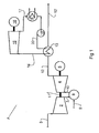
- Figure 1 illustrates a combined cycle gas turbine power plant 1 according to prior art.
- the prior art plant will be discussed as the present invention relates to a method and modification for capturing CO 2 from a power plant based on a combined cycle power plant.
- gas turbine is in the present invention used for a unit comprising a compressor 2, a combustion chamber 8 and turbine 4 mechanically connected to the compressor, most preferably connected on a common shaft 11.
- a “turbine” is used in the meaning of an expansion unit for converting of the energy of high temperature gas to rotational energy.
- carbonaceous fuel or “fuel” are in the present invention used for fuel suitable for a gas turbine such as natural gas, fluid hydrocarbons and oxygenated hydrocarbons such as methanol, ethanol etc., that will be in gas phase in the combustion chamber of a gas turbine, or gasified fuels such as gasified coal, gasified coke, gasified organic materials etc.
- Air is introduced into the compressor 2 through an air inlet line 3.
- the compressed air from the compressor 2 is introduced into a combustion chamber 8 via a compressed air line 7.
- Fuel such as e.g. natural gas, is introduced into the combustion chamber through a gas line 9.
- Combustion gas from the combustion chamber is led through a combustion gas line 10 and is expanded over a turbine 4 before the expanded gas is released through an exhaust gas line 12.
- the compressor 2, turbine 4 and a generator 5 for production of electric power are arranged on a common shaft 11.
- the exhaust gas in the exhaust gas line 12 is still hot, typically from 500 to 600°C, and is cooled by means of one or more heat exchanger(s) 13 to produce steam and cooled exhaust gas that is released into the surroundings through an exhaust outlet 12'.
- the steam produced in the heat exchanger(s) 13 is led in a steam line 14 into a steam turbine 15 where the steam is expanded.
- a generator 16 is connected to the steam turbine for production of electrical power.
- the expanded steam is led in an expanded steam line 17, cooled on a cooler 18, suitably against water, to condense the steam.
- the condensate is pumped by means of a pump 19 trough a water line 20 and is reintroduced into the heat exchanger(s) 13.
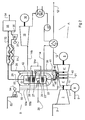
- Figure 2 illustrates a plant according to the present invention, comprising a modified combined cycle gas turbine part A and a CO 2 abatement part B.
- the turbine 4 normally comprises a high pressure turbine 4' and a low pressure turbine 4".
- partly expanded combustion gas is withdrawn from the turbine at an intermediate level of expansion, suitably between the high pressure 4' and low pressure 4" turbines, into a gas withdrawal line 20.
- a gas side draw unit 21 is preferably inserted at the shaft 11, after the high pressure turbine to facilitate the withdrawal of the partly expanded gas.
- the pressure at the point of gas withdrawal is for example in the range from 6 to 16 bara, such as 10 to 14 bara.
- the partly expanded gas in line 20 is combined with pressurized and heated air and introduced into a cooling chamber, where the combined gas is cooled by heating steam and/or generating of steam in a heating tube 22 in a primary cooling chamber 23.
- the gas mixture entering the cooling chamber has a temperature of about 1000 °C and is cooled therein to a temperature of about 400 to 500 °C.
- the combined and cooled gas in cooling chamber 23 is then introduced to a secondary cooling chamber 24 through a burner 25 where the combined gas is mixed with fuel gas that is introduced through a secondary fuel line 26.
- Air enters through an air supply line 52 and is compressed in a compressor 53 operated by means of an electric motor 54.
- the compressed air is supplied through lines 55 and 55a and used to protect pipes 20 and 39 and to cool the pressure container 50, before flowing to the secondary burner for firing purposes. Some of the air is supplied through line 55b and routed directly to combustor 25.
- the total amount of air from compressor 53 is adjusted relative to the captured CO2 withdrawn in line 34, so that the volume flow of gas to the gas turbine through line 39 is the same as, or very close to, the volume flow of gas withdrawn from the gas turbine through line 20.
- the fuel introduced into the secondary burner is adjusted so that the combustion in the secondary combustion chamber 24 is substantially complete, both with regard to oxygen and fuel.
- the combustion gases in the secondary cooling chamber are cooled by heating gas in a gas heating tube 27 and by superheating of steam from the heating tube 22 in a superheater tube 28.
- Heating tube 22 is connected to superheating tube 28 though a line 14a.
- the superheated steam in the superheating tube 28 is withdrawn through a line 14 b and introduced into steam turbine 15 to produce electrical energy, condensed and returned to the heat exchanger 13 as described above with reference to figure 1 .
- Exhaust gas from the secondary cooling chamber 24 is withdrawn through an exhaust line 29 and is cooled in a heat exchange assembly 30.
- a SCR (Selective Catalytic Reduction unit) or SNCR (Selective Non-Catalytic Reduction unit) 31 is provided in the heat exchange assembly 30 to remove NO x from the exhaust gas.
- the cooled gas from the heat exchange assembly 30 is withdrawn through a line 32 and introduced into a CO 2 separation unit 33.
- the CO 2 separation unit 33 is a standard unit according to the state of the art, e.g. a separation unit as described in WO 00/57990 , where CO 2 in the CO 2 containing gas is absorbed by countercurrent flow to a liquid absorbent in an absorber to produce a CO 2 lean stream that is withdrawn through a line 35.
- the CO 2 loaded absorbent is thereafter regenerated to produce a stream of CO 2 that is dried and compressed and is withdrawn through line 34 for export from the plant, and regenerated absorbent that is returned to the absorber.
- the absorbent may be any conventionally used absorbent, such as aqueous solutions of amines, amino acids, carbonates etc.
- the CO 2 capture unit may also include gas scrubbing and a direct contact gas cooler upstream of the CO 2 capture unit.
- a pressurized mantle 41 is preferably covering the high pressure and high temperature lines 20, 39.
- the mantle surrounding lines 20 and 39 is pressurized using air from a branch line 55a dividing from the compressed air line 55.
- the mantle reduces the pressure difference across the hot inner pipe wall, thus reducing the wall thickness and possibilities for cracks during temperature transients. Heated air from inside the mantle 41 is led from the mantle 41 to the mantle 50 through a line 42.
- additional air for the combustion in the secondary combustion chamber may be introduced through a second branch line 55b dividing from the compressed air line 55, to deliver additional air to the burner 25.
- This additional air has higher oxygen content than the air in line 20, and will stabilize the flame in one or more of the burners 25.
- the CO 2 lean stream in line 35 is compressed in one or more compressor(s) 36 operated by motor(s) 37, and is thereafter heated in the heat exchange assembly 30 towards the warm gas that is introduced through line 29.
- the heated CO 2 lean stream leaves the heat exchange assembly through a line 38 leading to the gas heating tube 27, where the gas is heated by the combustion gases from burner 25.
- the CO 2 lean gas leaves the gas heating tube 27 and is introduced into a gas return line 39 that is connected to a turbine inlet device 40 that is arranged on the shaft 11.
- the gas introduced to the inlet device 40 is then expanded over the low pressure turbine 4" and released into the exhaust gas line 12 as described with reference to figure 1 .
- the pressure, temperature and flow of the gas leaving the high pressure turbine 4' through line 20 should substantially be the same as the pressure, temperature and flow of the gas entering the low pressure turbine 4".
- the combustion in the secondary cooling chamber 24 adds temperature to the total gas, and especially to the CO 2 lean stream in line 38, and adds mass to the total gas to at least party compensate for the mass loss due to the removal of CO 2 . Additionally, heat is added to the steam cycle making it possible to increase the power production from the plant compared with the exemplary combined cycle plant according to figure 1 .
- Table 1 illustrates typical temperatures, mass flow and pressure, in addition to produced or consumed power for a typical combined cycle plant producing about 500 MW electrical power according to figure 1 .
- Table 1 Part No. Temp. °C Mass flow, kg/s Pressure, bara Produced / consumed electric power, MW 3 20 869 1 5 390 9 18.3 10 1343 887.3 30 12 520 887.3 1.04 12' 88 887.2 1 14 500 165 16 110
- Table 2 illustrates typical temperatures, mass flow and pressure, in addition to produced or consumed power for a typical plant with CO 2 capture according to the present invention, based on the combined cycle plant illustrated in table 1.
- Table 2 Part No. Temp. °C Mass flow, kg/s Pressure, bara Produced / consumed electric power, MW 3 20 869 1 5 390 9 18.3 10 1343 887.3 30 12 520 834.3 1.04 12' 88 834.3 1 14b 565 165 16 828 20 1013 887.3 10 26 31 52 51 34 135 39 13 834.3 10 37 -13 54 -17 33 -84
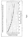
- Figures 3 to 7 illustrates a plant according to the present invention as described with reference to figure 2 (filled circles connected with a solid line) and a comparative example according to figure 1 is done with a 78% gas turbine load and a 22 % steam turbine load for a standard combined cycle plant (solid square)
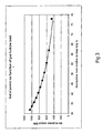
- Figure 3 illustrates the net electric power from a plant according to figure 2 , as a function of gas turbine load, included CO 2 capture and compression.
- the figure illustrates that the net electrical power output is reduced as the relative load on the gas turbine increases.
- the difference between the solid line for the present system including CO 2 capture and the comparative example is the electric output cost for the CO 2 capture.
- the production of electrical power from the gas turbine is constant, whereas the production from the steam turbine increases. The increased power production improves the lifetime production and economy of the plant.
- Figure 4 illustrates the net electrical efficiency as a function of the relative loads of the gas turbine and the steam turbine, including CO 2 capture for the plant according to the present invention.
- the difference between the solid line representing the present invention and the comparative example is the cost for CO 2 capture.
- the curve also illustrates that net electrical efficiency is reduced as the relative load of the gas turbine is reduced, as the steam turbine part of the process is less efficient than the gas turbine part.
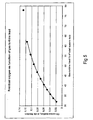
- Figure 5 illustrates the effect of the relative load on gas turbine and steam turbine on the residual oxygen content in the exhaust gas, or the gas to be treated by CO 2 capture.
- the curve clearly illustrates that the oxygen concentration is reduced with increasing steam turbine load.
- a low O 2 concentration is advantageous for the quality of the captured CO 2 .
- Oxygen present in the gas to be purified will be partly captured and will contaminate the CO 2 .
- CO 2 having a too high concentration of oxygen has to be further purified before deposition, a process that will add cost to the process.
- Figure 6 illustrates the partial pressure of CO 2 at the point of capture (i.e. in the exhaust gas in line 32 for the present invention, and line 12' for the comparative example).
- a higher partial pressure improves the CO 2 capture and enables the use of large scale commercial capture units, in addition to allowing the use of low energy absorbents, such as e.g. carbonates.
- Figure 7 illustrates the total volume of exhaust gas to be purified in a plant according to the present invention and the comparative example.
- the difference in total volume is a result of a difference in pressure (1 bara versus 10 bara).
- a smaller volume means that the process equipment may be less space consuming, and makes it possible to make more compact equipment and thereby reduce the capture equipment cost.
Landscapes
- Engineering & Computer Science (AREA)
- Chemical & Material Sciences (AREA)
- Combustion & Propulsion (AREA)
- Mechanical Engineering (AREA)
- General Engineering & Computer Science (AREA)
- Analytical Chemistry (AREA)
- Environmental & Geological Engineering (AREA)
- General Chemical & Material Sciences (AREA)
- Oil, Petroleum & Natural Gas (AREA)
- Chemical Kinetics & Catalysis (AREA)
- Engine Equipment That Uses Special Cycles (AREA)
- Treating Waste Gases (AREA)
- Industrial Gases (AREA)
- Gas Separation By Absorption (AREA)
Description
- The present invention relates to a method and a plant for capturing CO2 that may be implemented on an existing gas turbine power plant. The invention also relates to a gas turbine power plant including the inventive CO2 capturing, or CO2 abatement, plant.
- The last years, or the last decade, the increasing concentration of CO2 in the atmosphere due to increased combustion of fossil fuel, has caused great concern. The increased greenhouse effect caused by the increasing concentration of CO2 is expected to cause a substantial temperature increase at the planet earth and an enormous environmental impact in the next few decades.
- Actions therefore have to be taken to stabilize the CO2 concentration in the atmosphere. A substantial part of the man made CO2 emission is a result of power generation from oil, gas or coal. Accordingly, substantial efforts have been made to develop thermal power plants including capturing of CO2. Captured CO2 may be safely deposited into geological formations such as e.g. depleted oil or gas wells, or may be used as pressure support for increasing the production of oil or gas.
- The suggestions for CO2 capture mainly follow three lines of development:
- Post-combustion or "end of pipe" absorption of CO2 from the exhaust gas from a thermal power plant,
- Pre-combustion conversion of fuel where fossil fuel is converted mainly to hydrogen and CO2 in reformers. The product from the reformers contains CO2 at a high partial pressure and this CO2 is therefore relatively easy to separate from the hydrogen that is to be used as fuel, and
- Oxy-fuel systems where oxygen obtained by air separation is used together with CO2, replacing the normal air supply. This eliminates N2 from the system and increases the partial pressure of CO2, facilitating the separation of CO2.
- Much effort has been done on post-combustion absorption of CO2, both due to the fact that this technology is most developed and that the degree of integration with the power plant is small. Post combustion systems may be implemented on existing plants.
- The very low partial pressure of CO2 in the exhaust gas from a thermal power plant is, however, a major problem in making the CO2 capture economically acceptable. Absorbers become much larger than can be guaranteed with current technology, impeding the absorbent distribution in the absorber column and thus reducing the absorption efficiency. Additionally, the residual O2 concentration in the exhaust gas of most fossil fuel based thermal power plants is relatively high. This causes degradation problems for the required organic absorbent in the CO2 capturing system and, depending on the absorbent selectivity, potential contamination of the CO2 product.
- Pre-combustion conversion of fossil fuel to hydrogen is attractive because the reforming products are pressurized with high concentration of CO2. The CO2 is therefore much easier to capture than in post combustion systems. Conventional pressurized absorption columns may be employed. Disadvantages with the process include very complex processes for coal gasification, and the need to develop gas turbines for hydrogen fuel.
- Similar to the pre-combustion conversion of fossil fuel, oxy-fuel systems produce relatively high partial pressures of CO2. The CO2 therefore becomes much easier to capture than for post combustion systems. Disadvantages with the system include the need for very large and expensive air separation units, high energy requirement for oxygen production, and the new technologies required to use CO2 instead of nitrogen to cool flame temperatures. New gas turbines are also required when CO2 replaces nitrogen in the motive fluid. Risks of leaks and fire involving pure oxygen from the oxygen production unit will require large spatial separation between the oxygen plant and the power plant. This requirement increases the total area needed and will in particular increase the cost of offshore applications. Furthermore, the produced CO2 will contain unburned oxygen. This oxygen must be separated from the CO2 prior to for example injection in oil fields for enhanced oil recovery.
-
WO 2004/001301 , which is included as reference in the present application, relates to a low CO2 emission thermal power plant. CO2 is absorbed from the combustion gas from a combustion chamber in an absorber, wherein a liquid absorbent flows countercurrent to the combustion gas. This enriches the absorbent in CO2. The rich absorbent is regenerated by heating and stripping in a regeneration column by countercurrent flow to steam generated in a reboiler connected to the lower part of the regeneration column, to produce a stream of CO2 that is exported from the plant for deposition, and regenerated absorbent that is returned to the absorber. The partial pressure of CO2 is increased and the volume flow of flue gas to be purified is decreased, relative to the power produced, by substantially complete combustion of both oxygen and fuel in a pressurized combustion chamber. This improves the capture of CO2, which occurs at high pressure.WO 2004/001301 is, however, suitable either for thermal power plants having a pressurised combustion chamber for production of steam, or for new plants. -
WO 2005/045316 relates to a purification works for a thermal power plant, where the combustion gas from an existing thermal power plant is used as all, or a substantial part of, the oxygen containing gas that is introduced into a plant built at the basic principle ofWO 2004/001301 , to capture the CO2 from both plants and increase the total production of electrical power, at the same time. A highly efficient gas turbine is used as a primary power plant. Air is first compressed in a primary power plant compressor, then heated and expanded to atmospheric pressure. A secondary power plant provides additional power and carries out CO2 capture under pressure. The main shortcoming of this technology is the need to re-compress the gas from the primary unit. Such recompression requires significant work and causes loss of thermal efficiency. - There is, however, need for a system which as far as possible uses the advantages of the highly efficient, high temperature gas turbines in combination with pressurized CO2 capture, without the need to re-compress gas from atmospheric pressure.
- An objective is therefore to provide an improved method and plant for capturing CO2 from a gas turbine. It is also an objective to provide solution that is suitable for post-installation for an existing gas turbine or combined cycle power plant.
- According to a first embodiment, the present invention relates a method for separation of CO2 from the combustion gas of a gas turbine where carbonaceous fuel and compressed oxygen containing gas are combusted, and the combustion gas is expanded over a turbine to produce electrical power in a generator before the expanded combustion gas is released into the atmosphere, the method additionally comprises the steps of:
- a) withdrawing the combustion gas at an intermediate stage of the turbine,
- b) introducing the withdrawn combustion gas into a burner together with compressed air and additional carbonaceous fuel to cause a secondary combustion therein,
- c) cooling the combustion gas from the burner,
- d) introducing the cooled combustion gas into a CO2 capturing unit, to separate the combustion gas into a CO2 rich gas, that is withdrawn for deposition, and a CO2 lean gas, and
- e) reheating and reintroducing the CO2 lean gas into the turbine at an intermediate level and further expand the gas before it is released into the atmosphere.
- Withdrawing partly expanded gas from an intermediate level of the turbine and introduction of the partly expanded, gas that are still at an elevated pressure, into the burner for a second combustion, allows for a combustion and succeeding CO2 capture at an elevated pressure. Additionally, the heat and pressure energy of the gas that is withdrawn is at least partly conserved and is used by reheating of the CO2 lean gas and expanding the same over the turbine,
- According to one embodiment, the method additionally comprises the step of cooling the withdrawn combustion gas of step a) before the gas is introduced into the burner in step b). Cooling of the gas before it is introduced into to burner reduces the temperature of the flare in the burner, as the flare otherwise may become too hot and produce high levels of NOx. Additionally high temperatures may result in problems related to the materials of the components of the plant
- The secondary combustion in the burner adds mass to the total gas flow to substitute the mass of CO2 that is removed from the total mass of gas. Performing this combustion and the CO2 capture downstream of the burner reduces the oxygen level in the gas and increases the CO2 level, which both are important for the efficiency of the capturing process. Re-heating of the CO2 depleted gas and expanding the gas over the turbine increases the energy efficiency of the plant considerably.
- According to a second aspect, the present invention relates to a plant for generation of power comprising a gas turbine, and a generator operated by the gas turbine, wherein the plant additionally comprises a gas side draw unit for withdrawal of partly expanded gas from an intermediate stage of the turbine, a burner for a secondary combustion of fuel, using the partly expanded gas and additional air as sources for oxygen, one or more heat exchanger(s) for cooling the combustion gas from the secondary combustion, CO2 separation unit for separation of the cooled combustion gas into a CO2 rich gas that is treated further and exported from the plant, and a CO2 lean gas, one or more heat exchanger(s) for reheating the CO2 lean gas, and gas a gas return line and a turbine inlet unit for introduction of the heated CO2 lean gas at an intermediate level of the turbine for further expansion.
-
-
Figure 1 is a principle sketch of a combined cycle gas powered power plant according to the state of the art, -
Figure 2 is a principle sketch of an embodiment of the present invention, -
Figure 3 is a graph illustrating the net power output from a power plant according to the invention as a function of gas turbine load relative to total duty, -
Figure 4 is a graph illustrating the net electric efficiency from a power plant according to the invention as a function of gas turbine load relative to total duty, -
Figure 5 is a graph illustrating the residual oxygen in the exhaust gas to be purified in a power plant according to the invention as a function of gas turbine load relative to total duty, -
Figure 6 is a graph illustrating partial pressure of CO2 in the exhaust gas to be purified in a power plant according to the invention as a function of gas turbine load relative to total duty, and -
Figure 7 is a graph illustrating the actual volume of exhaust gas to be purified in a power plant according to the invention as a function of gas turbine load relative to total duty. -
Figure 1 illustrates a combined cycle gasturbine power plant 1 according to prior art. The prior art plant will be discussed as the present invention relates to a method and modification for capturing CO2 from a power plant based on a combined cycle power plant. The term "gas turbine" is in the present invention used for a unit comprising acompressor 2, acombustion chamber 8 andturbine 4 mechanically connected to the compressor, most preferably connected on a common shaft 11. A "turbine" is used in the meaning of an expansion unit for converting of the energy of high temperature gas to rotational energy. - The terms "carbonaceous fuel" or "fuel" are in the present invention used for fuel suitable for a gas turbine such as natural gas, fluid hydrocarbons and oxygenated hydrocarbons such as methanol, ethanol etc., that will be in gas phase in the combustion chamber of a gas turbine, or gasified fuels such as gasified coal, gasified coke, gasified organic materials etc.
- Air is introduced into the
compressor 2 through anair inlet line 3. The compressed air from thecompressor 2 is introduced into acombustion chamber 8 via acompressed air line 7. Fuel, such as e.g. natural gas, is introduced into the combustion chamber through a gas line 9. Combustion gas from the combustion chamber is led through acombustion gas line 10 and is expanded over aturbine 4 before the expanded gas is released through anexhaust gas line 12. - As indicated in the figure, the
compressor 2,turbine 4 and agenerator 5 for production of electric power, are arranged on a common shaft 11. - The exhaust gas in the
exhaust gas line 12 is still hot, typically from 500 to 600°C, and is cooled by means of one or more heat exchanger(s) 13 to produce steam and cooled exhaust gas that is released into the surroundings through an exhaust outlet 12'. - The steam produced in the heat exchanger(s) 13 is led in a
steam line 14 into asteam turbine 15 where the steam is expanded. Agenerator 16 is connected to the steam turbine for production of electrical power. - The expanded steam is led in an expanded steam line 17, cooled on a cooler 18, suitably against water, to condense the steam. The condensate is pumped by means of a
pump 19 trough awater line 20 and is reintroduced into the heat exchanger(s) 13. - Typically, about 75 to 80 % of the electrical power from a combined cycle power plant is generated in the
generator 5 operated by theturbine 4 and the rest ingenerator 16, operated by thesteam turbine 15. -
Figure 2 illustrates a plant according to the present invention, comprising a modified combined cycle gas turbine part A and a CO2 abatement part B. - Parts corresponding to parts described with reference to
figure 1 are referred to using the same reference numbers as used forfigure 1 . - The
turbine 4 normally comprises a high pressure turbine 4' and alow pressure turbine 4". According to the present invention, partly expanded combustion gas is withdrawn from the turbine at an intermediate level of expansion, suitably between the high pressure 4' andlow pressure 4" turbines, into agas withdrawal line 20. A gasside draw unit 21 is preferably inserted at the shaft 11, after the high pressure turbine to facilitate the withdrawal of the partly expanded gas. The pressure at the point of gas withdrawal is for example in the range from 6 to 16 bara, such as 10 to 14 bara. - The partly expanded gas in
line 20 is combined with pressurized and heated air and introduced into a cooling chamber, where the combined gas is cooled by heating steam and/or generating of steam in aheating tube 22 in aprimary cooling chamber 23. The gas mixture entering the cooling chamber has a temperature of about 1000 °C and is cooled therein to a temperature of about 400 to 500 °C. The combined and cooled gas in coolingchamber 23 is then introduced to asecondary cooling chamber 24 through aburner 25 where the combined gas is mixed with fuel gas that is introduced through asecondary fuel line 26. Air enters through anair supply line 52 and is compressed in acompressor 53 operated by means of anelectric motor 54. - The compressed air is supplied through
lines pipes pressure container 50, before flowing to the secondary burner for firing purposes. Some of the air is supplied throughline 55b and routed directly tocombustor 25. The total amount of air fromcompressor 53 is adjusted relative to the captured CO2 withdrawn inline 34, so that the volume flow of gas to the gas turbine throughline 39 is the same as, or very close to, the volume flow of gas withdrawn from the gas turbine throughline 20. The fuel introduced into the secondary burner is adjusted so that the combustion in thesecondary combustion chamber 24 is substantially complete, both with regard to oxygen and fuel. - The combustion gases in the secondary cooling chamber are cooled by heating gas in a
gas heating tube 27 and by superheating of steam from theheating tube 22 in asuperheater tube 28.Heating tube 22 is connected to superheatingtube 28 though aline 14a. The superheated steam in the superheatingtube 28 is withdrawn through aline 14 b and introduced intosteam turbine 15 to produce electrical energy, condensed and returned to theheat exchanger 13 as described above with reference tofigure 1 . - Exhaust gas from the
secondary cooling chamber 24 is withdrawn through anexhaust line 29 and is cooled in aheat exchange assembly 30. Preferably a SCR (Selective Catalytic Reduction unit) or SNCR (Selective Non-Catalytic Reduction unit) 31 is provided in theheat exchange assembly 30 to remove NOx from the exhaust gas. - The cooled gas from the
heat exchange assembly 30 is withdrawn through aline 32 and introduced into a CO2 separation unit 33. The CO2 separation unit 33 is a standard unit according to the state of the art, e.g. a separation unit as described inWO 00/57990 line 35. The CO2 loaded absorbent is thereafter regenerated to produce a stream of CO2 that is dried and compressed and is withdrawn throughline 34 for export from the plant, and regenerated absorbent that is returned to the absorber. The absorbent may be any conventionally used absorbent, such as aqueous solutions of amines, amino acids, carbonates etc. The CO2 capture unit may also include gas scrubbing and a direct contact gas cooler upstream of the CO2 capture unit. - A
pressurized mantle 41 is preferably covering the high pressure andhigh temperature lines mantle surrounding lines branch line 55a dividing from thecompressed air line 55. The mantle reduces the pressure difference across the hot inner pipe wall, thus reducing the wall thickness and possibilities for cracks during temperature transients. Heated air from inside themantle 41 is led from themantle 41 to themantle 50 through aline 42. - If necessary, additional air for the combustion in the secondary combustion chamber may be introduced through a
second branch line 55b dividing from thecompressed air line 55, to deliver additional air to theburner 25. This additional air has higher oxygen content than the air inline 20, and will stabilize the flame in one or more of theburners 25. - The CO2 lean stream in
line 35 is compressed in one or more compressor(s) 36 operated by motor(s) 37, and is thereafter heated in theheat exchange assembly 30 towards the warm gas that is introduced throughline 29. The heated CO2 lean stream leaves the heat exchange assembly through aline 38 leading to thegas heating tube 27, where the gas is heated by the combustion gases fromburner 25. The CO2 lean gas leaves thegas heating tube 27 and is introduced into agas return line 39 that is connected to aturbine inlet device 40 that is arranged on the shaft 11. The gas introduced to theinlet device 40 is then expanded over thelow pressure turbine 4" and released into theexhaust gas line 12 as described with reference tofigure 1 . - Closing
valves lines shortcut line 43 with a shortcut valve 44, are preferably provided to closeline side draw unit 21 to flow directly into thegas inlet device 40 if necessary. - To balance the turbine correctly, the pressure, temperature and flow of the gas leaving the high pressure turbine 4' through
line 20 should substantially be the same as the pressure, temperature and flow of the gas entering thelow pressure turbine 4". The combustion in thesecondary cooling chamber 24 adds temperature to the total gas, and especially to the CO2 lean stream inline 38, and adds mass to the total gas to at least party compensate for the mass loss due to the removal of CO2. Additionally, heat is added to the steam cycle making it possible to increase the power production from the plant compared with the exemplary combined cycle plant according tofigure 1 . - Table 1 illustrates typical temperatures, mass flow and pressure, in addition to produced or consumed power for a typical combined cycle plant producing about 500 MW electrical power according to
figure 1 .Table 1 Part No. Temp. °C Mass flow, kg/s Pressure, bara Produced / consumed electric power, MW 3 20 869 1 5 390 9 18.3 10 1343 887.3 30 12 520 887.3 1.04 12' 88 887.2 1 14 500 165 16 110 - Table 2 illustrates typical temperatures, mass flow and pressure, in addition to produced or consumed power for a typical plant with CO2 capture according to the present invention, based on the combined cycle plant illustrated in table 1.
Table 2 Part No. Temp. °C Mass flow, kg/s Pressure, bara Produced / consumed electric power, MW 3 20 869 1 5 390 9 18.3 10 1343 887.3 30 12 520 834.3 1.04 12' 88 834.3 1 14b 565 165 16 828 20 1013 887.3 10 26 31 52 51 34 135 39 13 834.3 10 37 -13 54 -17 33 -84 -
Figures 3 to 7 illustrates a plant according to the present invention as described with reference tofigure 2 (filled circles connected with a solid line) and a comparative example according tofigure 1 is done with a 78% gas turbine load and a 22 % steam turbine load for a standard combined cycle plant (solid square) -
Figure 3 illustrates the net electric power from a plant according tofigure 2 , as a function of gas turbine load, included CO2 capture and compression. The figure illustrates that the net electrical power output is reduced as the relative load on the gas turbine increases. The difference between the solid line for the present system including CO2 capture and the comparative example is the electric output cost for the CO2 capture. The production of electrical power from the gas turbine is constant, whereas the production from the steam turbine increases. The increased power production improves the lifetime production and economy of the plant. -
Figure 4 illustrates the net electrical efficiency as a function of the relative loads of the gas turbine and the steam turbine, including CO2 capture for the plant according to the present invention. The difference between the solid line representing the present invention and the comparative example is the cost for CO2 capture. The curve also illustrates that net electrical efficiency is reduced as the relative load of the gas turbine is reduced, as the steam turbine part of the process is less efficient than the gas turbine part. -
Figure 5 illustrates the effect of the relative load on gas turbine and steam turbine on the residual oxygen content in the exhaust gas, or the gas to be treated by CO2 capture. The curve clearly illustrates that the oxygen concentration is reduced with increasing steam turbine load. A low O2 concentration is advantageous for the quality of the captured CO2. Oxygen present in the gas to be purified will be partly captured and will contaminate the CO2. CO2 having a too high concentration of oxygen has to be further purified before deposition, a process that will add cost to the process. -
Figure 6 illustrates the partial pressure of CO2 at the point of capture (i.e. in the exhaust gas inline 32 for the present invention, and line 12' for the comparative example). The higher the steam turbine load is, the higher is partial pressure of CO2. The difference between CO2 partial pressure in the present plant and the comparative example, at a low steam turbine load, is due to the higher total pressure (of about 10 bara) in the combustion gas inline 32, compared with 1 bara in line 12'. A higher partial pressure improves the CO2 capture and enables the use of large scale commercial capture units, in addition to allowing the use of low energy absorbents, such as e.g. carbonates. -
Figure 7 illustrates the total volume of exhaust gas to be purified in a plant according to the present invention and the comparative example. The difference in total volume is a result of a difference in pressure (1 bara versus 10 bara). A smaller volume means that the process equipment may be less space consuming, and makes it possible to make more compact equipment and thereby reduce the capture equipment cost.
Claims (14)
- A method for separation of CO2 from the combustion gas of a gas turbine (2, 8, 4) where carbonaceous fuel and compressed oxygen containing gas are combusted, and the combustion gas is expanded over a turbine (4) to produce electrical power in a generator (5) before the expanded combustion gas is released into the atmosphere, c h a r a c t e r i s e d i n that the method additionally comprises the steps of:a) withdrawing the combustion gas at an intermediate stage (21) of the turbine (4),b) introducing the withdrawn combustion gas into a burner (25)together with compressed air and additional carbonaceous fuel to cause a secondary combustion therein,c) cooling the combustion gas from the burner (25),d) introducing the cooled combustion gas into a CO2 capturing unit (33, to separate the combustion gas into a CO2 rich gas, that is withdrawn for deposition, and a CO2 lean gas, ande) reheating and reintroducing the CO2 lean gas into the turbine (4) at an intermediate level (40) and further expand the gas before it is released into the atmosphere.
- The method according to claim 1, additionally comprising the step of cooling the withdrawn combustion gas of step a) before the gas is introduced into the burner (25) in step b).
- The method according to claim 1 or 2, wherein the combustion gas from the burner (25) is cooled by producing steam in cooling tubes (28) in a cooling chamber (24).
- The method of claim 3, wherein the steam produced in cooling the combustion chamber (25) is expanded over a steam turbine (15) to produce electrical power.
- The method according to any of the preceding claims, wherein CO2 lean gas is heated by heat exchanging (30) against the combustion gas that is to be introduced into the CO2 capturing unit (33), before the CO2 lean gas is introduced into the turbine (4).
- The method according to any of the preceding claims, wherein the additional carbonaceous fuel and air that are introduced into the burner (25) are regulated to give a substantially stoichiometric combustion in the burner (25).
- The method according to any of the preceding claims, wherein the carbonaceous fuel is oil or natural gas.
- The method according to any of the preceding claims, wherein the natural gas and air that are introduced into the burner (5) are regulated so that the mass flow of the CO2 lean gas that is introduced to the turbine (4) at an intermediate stage is substantially equal to the mass flow of the gas that is withdrawn from the turbine at an intermediate level.
- A plant for generation of power comprising a gas turbine (2, 8, 4), and a generator (5) operated by the gas turbine, wherein the plant additionally comprises a gas side draw unit (21) for withdrawal of partly expanded gas from an intermediate stage of the turbine (4'), a burner (25) for a secondary combustion of fuel, using the partly expanded gas and additional air as sources for oxygen, one or more heat exchanger(s) (28, 30) for cooling the combustion gas from the secondary combustion, CO2 separation unit (33) for separation of the cooled combustion gas into a CO2 rich gas that is treated further and exported from the plant, and a CO2 lean gas, one or more heat exchanger(s) (30, 27) for reheating the CO2 lean gas, and gas a gas return line (39) and a turbine inlet unit (40) for introduction of the heated CO2 lean gas at an intermediate level of the turbine (4") for further expansion.
- The plant according to claim 9, wherein the plant additionally comprises a cooling chamber (23) for cooling the partly expanded gas arranged between the intermediate step of the turbine 4' and the burner (25).
- The plant according to claim 9 or 10, wherein the plant additionally comprises a heat exchanger (30) for cooling of the gas leaving the secondary combustion against the CO2 lean gas leaving the separation unit (33), before the combustion gas is introduced into the separation unit.
- The plant according to any of the claims 9 to 11, wherein superheater tubes (28) are provided in a secondary cooling chamber (24) for cooling of the combustion gas from the burner (25) by generation and / or superheating of steam within the tubes upstream of the separation unit (33).
- The plant according to any of the claims 9 to 12, wherein heating tubes (22) are provided in a primary cooling chamber (23) for cooling the partly expanded gas before introduction into the burner (25), by generation of steam within the heating tubes.
- The plant according to any of the claims 9 to 13, wherein gas heating tubes (27) are arranged in the secondary cooling chamber to heat the CO2 lean gas leaving the heat exchanger (30) against combustion gas from the burner (25).
Applications Claiming Priority (2)
| Application Number | Priority Date | Filing Date | Title |
|---|---|---|---|
| NO20081051A NO328975B1 (en) | 2008-02-28 | 2008-02-28 | Gas power plant with CO2 purification |
| PCT/NO2009/000066 WO2009108065A2 (en) | 2008-02-28 | 2009-02-26 | Thermal power plant with co2 sequestration |
Publications (2)
| Publication Number | Publication Date |
|---|---|
| EP2300129A2 EP2300129A2 (en) | 2011-03-30 |
| EP2300129B1 true EP2300129B1 (en) | 2012-09-05 |
Family
ID=41016621
Family Applications (1)
| Application Number | Title | Priority Date | Filing Date |
|---|---|---|---|
| EP09715173A Active EP2300129B1 (en) | 2008-02-28 | 2009-02-26 | Thermal power plant with co2 sequestration |
Country Status (8)
| Country | Link |
|---|---|
| US (1) | US20110094237A1 (en) |
| EP (1) | EP2300129B1 (en) |
| KR (1) | KR101586105B1 (en) |
| CN (1) | CN102084105B (en) |
| CA (1) | CA2717051C (en) |
| DK (1) | DK2300129T3 (en) |
| NO (1) | NO328975B1 (en) |
| WO (1) | WO2009108065A2 (en) |
Families Citing this family (9)
| Publication number | Priority date | Publication date | Assignee | Title |
|---|---|---|---|---|
| US8171718B2 (en) * | 2009-10-05 | 2012-05-08 | General Electric Company | Methods and systems involving carbon sequestration and engines |
| CN103096999A (en) * | 2010-07-28 | 2013-05-08 | 萨加斯公司 | Jet engine with carbon capture |
| ES2551865T3 (en) | 2011-02-01 | 2015-11-24 | Alstom Technology Ltd | Apparatus and system for NOx reduction in wet combustion gas |
| WO2013139884A2 (en) * | 2012-03-21 | 2013-09-26 | Alstom Technology Ltd | Combined cycle power plant |
| EP2706211A1 (en) * | 2012-09-10 | 2014-03-12 | Siemens Aktiengesellschaft | Gas turbine assembly with post-combustion device for CO2 separation |
| WO2014202385A1 (en) * | 2013-06-17 | 2014-12-24 | Siemens Aktiengesellschaft | Gas turbine system and method for operating such a gas turbine system |
| CN103499980A (en) * | 2013-09-11 | 2014-01-08 | 绥中泰德尔自控设备有限公司 | Static balance valve wireless network debugging device |
| US11578652B2 (en) * | 2019-08-12 | 2023-02-14 | Enexor Energy, Llc | Combined heat and power system and method of operation |
| CN120035461A (en) | 2022-09-06 | 2025-05-23 | 卡普索尔技术公司 | Carbon capture for gas turbines |
Family Cites Families (10)
| Publication number | Priority date | Publication date | Assignee | Title |
|---|---|---|---|---|
| US4498289A (en) * | 1982-12-27 | 1985-02-12 | Ian Osgerby | Carbon dioxide power cycle |
| US4899544A (en) * | 1987-08-13 | 1990-02-13 | Boyd Randall T | Cogeneration/CO2 production process and plant |
| DE69533558T2 (en) * | 1994-08-25 | 2005-11-24 | Clean Energy Systems, Inc., Sacramento | GAS MANAGER FOR A LOW ENVIRONMENTAL ENERGY GENERATION SYSTEM |
| US6170264B1 (en) * | 1997-09-22 | 2001-01-09 | Clean Energy Systems, Inc. | Hydrocarbon combustion power generation system with CO2 sequestration |
| NO20023050L (en) * | 2002-06-21 | 2003-12-22 | Fleischer & Co | Process and facilities for carrying out the process |
| FR2852358B1 (en) * | 2003-03-13 | 2006-06-09 | METHOD AND DEVICE FOR COGENERATION BY GAS TURBINE WITH POSTCOMBUSTION CHAMBER | |
| DE10360951A1 (en) * | 2003-12-23 | 2005-07-28 | Alstom Technology Ltd | Thermal power plant with sequential combustion and reduced CO2 emissions and method of operating such a plant |
| WO2006107209A1 (en) * | 2005-04-05 | 2006-10-12 | Sargas As | Low co2 thermal powerplant |
| US7574855B2 (en) * | 2005-08-10 | 2009-08-18 | Alstom Technology Ltd. | Method for operating a gas turbine and a gas turbine for implementing the method |
| US7726114B2 (en) * | 2005-12-07 | 2010-06-01 | General Electric Company | Integrated combustor-heat exchanger and systems for power generation using the same |
-
2008
- 2008-02-28 NO NO20081051A patent/NO328975B1/en unknown
-
2009
- 2009-02-26 CA CA2717051A patent/CA2717051C/en active Active
- 2009-02-26 WO PCT/NO2009/000066 patent/WO2009108065A2/en not_active Ceased
- 2009-02-26 CN CN200980113698.5A patent/CN102084105B/en active Active
- 2009-02-26 KR KR1020107021548A patent/KR101586105B1/en active Active
- 2009-02-26 EP EP09715173A patent/EP2300129B1/en active Active
- 2009-02-26 US US12/919,775 patent/US20110094237A1/en not_active Abandoned
- 2009-02-26 DK DK09715173.2T patent/DK2300129T3/en active
Also Published As
| Publication number | Publication date |
|---|---|
| WO2009108065A2 (en) | 2009-09-03 |
| CN102084105B (en) | 2014-05-14 |
| NO20081051L (en) | 2009-08-31 |
| WO2009108065A3 (en) | 2011-06-03 |
| KR20100138975A (en) | 2010-12-31 |
| DK2300129T3 (en) | 2012-12-03 |
| CA2717051C (en) | 2016-04-12 |
| NO328975B1 (en) | 2010-07-05 |
| KR101586105B1 (en) | 2016-01-22 |
| HK1158289A1 (en) | 2012-07-13 |
| CN102084105A (en) | 2011-06-01 |
| CA2717051A1 (en) | 2009-09-03 |
| EP2300129A2 (en) | 2011-03-30 |
| US20110094237A1 (en) | 2011-04-28 |
Similar Documents
| Publication | Publication Date | Title |
|---|---|---|
| CA2717051C (en) | Thermal power plant with co2 sequestration | |
| US7726114B2 (en) | Integrated combustor-heat exchanger and systems for power generation using the same | |
| TWI564475B (en) | Low emission triple-cycle power generation systems and methods | |
| US7739864B2 (en) | Systems and methods for power generation with carbon dioxide isolation | |
| US7882692B2 (en) | Zero emissions closed rankine cycle power system | |
| JP5913304B2 (en) | Low emission triple cycle power generation system and method | |
| JP5906555B2 (en) | Stoichiometric combustion of rich air by exhaust gas recirculation system | |
| CN1316145C (en) | Integrated air separation and power generation process | |
| US20130119667A1 (en) | Jet engine with carbon capture | |
| EP3762130B1 (en) | Carbon capture system comprising a gas turbine | |
| US20140374109A1 (en) | Enhanced Carbon Dioxide Capture in a Combined Cycle Plant | |
| EA038310B1 (en) | Method for power production | |
| CA2828365A1 (en) | Systems and methods for carbon dioxide capture in low emission turbine systems | |
| Hoffmann et al. | Performance and cost analysis of advanced gas turbine cycles with pre-combustion CO2 capture | |
| HK1158289B (en) | Thermal power plant with co2 sequestration | |
| Srinivas et al. | Carbon dioxide emission reduction from combined cycle with partial oxidation of natural gas | |
| HK40049442A (en) | Carbon capture system comprising a gas turbine | |
| HK40049442B (en) | Carbon capture system comprising a gas turbine |
Legal Events
| Date | Code | Title | Description |
|---|---|---|---|
| PUAI | Public reference made under article 153(3) epc to a published international application that has entered the european phase |
Free format text: ORIGINAL CODE: 0009012 |
|
| 17P | Request for examination filed |
Effective date: 20100927 |
|
| AK | Designated contracting states |
Kind code of ref document: A2 Designated state(s): AT BE BG CH CY CZ DE DK EE ES FI FR GB GR HR HU IE IS IT LI LT LU LV MC MK MT NL NO PL PT RO SE SI SK TR |
|
| AX | Request for extension of the european patent |
Extension state: AL BA RS |
|
| DAX | Request for extension of the european patent (deleted) | ||
| R17D | Deferred search report published (corrected) |
Effective date: 20110603 |
|
| REG | Reference to a national code |
Ref country code: DE Ref legal event code: R079 Ref document number: 602009009459 Country of ref document: DE Free format text: PREVIOUS MAIN CLASS: B01D0053140000 Ipc: F02C0006180000 |
|
| GRAP | Despatch of communication of intention to grant a patent |
Free format text: ORIGINAL CODE: EPIDOSNIGR1 |
|
| RIC1 | Information provided on ipc code assigned before grant |
Ipc: B01D 53/14 20060101ALI20120302BHEP Ipc: F02C 6/18 20060101AFI20120302BHEP Ipc: F01K 23/10 20060101ALI20120302BHEP Ipc: B01D 53/02 20060101ALI20120302BHEP |
|
| RIN1 | Information on inventor provided before grant (corrected) |
Inventor name: CHRISTENSEN, TOR Inventor name: FLEISCHER, HENRIK Inventor name: BOERSETH, KNUT |
|
| GRAS | Grant fee paid |
Free format text: ORIGINAL CODE: EPIDOSNIGR3 |
|
| GRAA | (expected) grant |
Free format text: ORIGINAL CODE: 0009210 |
|
| RAP1 | Party data changed (applicant data changed or rights of an application transferred) |
Owner name: SARGAS AS |
|
| AK | Designated contracting states |
Kind code of ref document: B1 Designated state(s): AT BE BG CH CY CZ DE DK EE ES FI FR GB GR HR HU IE IS IT LI LT LU LV MC MK MT NL NO PL PT RO SE SI SK TR |
|
| REG | Reference to a national code |
Ref country code: GB Ref legal event code: FG4D |
|
| REG | Reference to a national code |
Ref country code: CH Ref legal event code: EP |
|
| REG | Reference to a national code |
Ref country code: AT Ref legal event code: REF Ref document number: 574246 Country of ref document: AT Kind code of ref document: T Effective date: 20120915 |
|
| REG | Reference to a national code |
Ref country code: IE Ref legal event code: FG4D |
|
| REG | Reference to a national code |
Ref country code: DE Ref legal event code: R096 Ref document number: 602009009459 Country of ref document: DE Effective date: 20121031 |
|
| REG | Reference to a national code |
Ref country code: NL Ref legal event code: T3 |
|
| REG | Reference to a national code |
Ref country code: DK Ref legal event code: T3 |
|
| REG | Reference to a national code |
Ref country code: AT Ref legal event code: MK05 Ref document number: 574246 Country of ref document: AT Kind code of ref document: T Effective date: 20120905 |
|
| PG25 | Lapsed in a contracting state [announced via postgrant information from national office to epo] |
Ref country code: HR Free format text: LAPSE BECAUSE OF FAILURE TO SUBMIT A TRANSLATION OF THE DESCRIPTION OR TO PAY THE FEE WITHIN THE PRESCRIBED TIME-LIMIT Effective date: 20120905 Ref country code: FI Free format text: LAPSE BECAUSE OF FAILURE TO SUBMIT A TRANSLATION OF THE DESCRIPTION OR TO PAY THE FEE WITHIN THE PRESCRIBED TIME-LIMIT Effective date: 20120905 Ref country code: AT Free format text: LAPSE BECAUSE OF FAILURE TO SUBMIT A TRANSLATION OF THE DESCRIPTION OR TO PAY THE FEE WITHIN THE PRESCRIBED TIME-LIMIT Effective date: 20120905 Ref country code: LT Free format text: LAPSE BECAUSE OF FAILURE TO SUBMIT A TRANSLATION OF THE DESCRIPTION OR TO PAY THE FEE WITHIN THE PRESCRIBED TIME-LIMIT Effective date: 20120905 Ref country code: NO Free format text: LAPSE BECAUSE OF FAILURE TO SUBMIT A TRANSLATION OF THE DESCRIPTION OR TO PAY THE FEE WITHIN THE PRESCRIBED TIME-LIMIT Effective date: 20121205 |
|
| REG | Reference to a national code |
Ref country code: LT Ref legal event code: MG4D Effective date: 20120905 |
|
| PG25 | Lapsed in a contracting state [announced via postgrant information from national office to epo] |
Ref country code: LV Free format text: LAPSE BECAUSE OF FAILURE TO SUBMIT A TRANSLATION OF THE DESCRIPTION OR TO PAY THE FEE WITHIN THE PRESCRIBED TIME-LIMIT Effective date: 20120905 Ref country code: GR Free format text: LAPSE BECAUSE OF FAILURE TO SUBMIT A TRANSLATION OF THE DESCRIPTION OR TO PAY THE FEE WITHIN THE PRESCRIBED TIME-LIMIT Effective date: 20121206 Ref country code: SI Free format text: LAPSE BECAUSE OF FAILURE TO SUBMIT A TRANSLATION OF THE DESCRIPTION OR TO PAY THE FEE WITHIN THE PRESCRIBED TIME-LIMIT Effective date: 20120905 Ref country code: SE Free format text: LAPSE BECAUSE OF FAILURE TO SUBMIT A TRANSLATION OF THE DESCRIPTION OR TO PAY THE FEE WITHIN THE PRESCRIBED TIME-LIMIT Effective date: 20120905 |
|
| PG25 | Lapsed in a contracting state [announced via postgrant information from national office to epo] |
Ref country code: EE Free format text: LAPSE BECAUSE OF FAILURE TO SUBMIT A TRANSLATION OF THE DESCRIPTION OR TO PAY THE FEE WITHIN THE PRESCRIBED TIME-LIMIT Effective date: 20120905 Ref country code: RO Free format text: LAPSE BECAUSE OF FAILURE TO SUBMIT A TRANSLATION OF THE DESCRIPTION OR TO PAY THE FEE WITHIN THE PRESCRIBED TIME-LIMIT Effective date: 20120905 Ref country code: ES Free format text: LAPSE BECAUSE OF FAILURE TO SUBMIT A TRANSLATION OF THE DESCRIPTION OR TO PAY THE FEE WITHIN THE PRESCRIBED TIME-LIMIT Effective date: 20121216 Ref country code: BE Free format text: LAPSE BECAUSE OF FAILURE TO SUBMIT A TRANSLATION OF THE DESCRIPTION OR TO PAY THE FEE WITHIN THE PRESCRIBED TIME-LIMIT Effective date: 20120905 Ref country code: IS Free format text: LAPSE BECAUSE OF FAILURE TO SUBMIT A TRANSLATION OF THE DESCRIPTION OR TO PAY THE FEE WITHIN THE PRESCRIBED TIME-LIMIT Effective date: 20130105 |
|
| PG25 | Lapsed in a contracting state [announced via postgrant information from national office to epo] |
Ref country code: PT Free format text: LAPSE BECAUSE OF FAILURE TO SUBMIT A TRANSLATION OF THE DESCRIPTION OR TO PAY THE FEE WITHIN THE PRESCRIBED TIME-LIMIT Effective date: 20130107 Ref country code: PL Free format text: LAPSE BECAUSE OF FAILURE TO SUBMIT A TRANSLATION OF THE DESCRIPTION OR TO PAY THE FEE WITHIN THE PRESCRIBED TIME-LIMIT Effective date: 20120905 Ref country code: SK Free format text: LAPSE BECAUSE OF FAILURE TO SUBMIT A TRANSLATION OF THE DESCRIPTION OR TO PAY THE FEE WITHIN THE PRESCRIBED TIME-LIMIT Effective date: 20120905 |
|
| PLBE | No opposition filed within time limit |
Free format text: ORIGINAL CODE: 0009261 |
|
| STAA | Information on the status of an ep patent application or granted ep patent |
Free format text: STATUS: NO OPPOSITION FILED WITHIN TIME LIMIT |
|
| PG25 | Lapsed in a contracting state [announced via postgrant information from national office to epo] |
Ref country code: BG Free format text: LAPSE BECAUSE OF FAILURE TO SUBMIT A TRANSLATION OF THE DESCRIPTION OR TO PAY THE FEE WITHIN THE PRESCRIBED TIME-LIMIT Effective date: 20121205 |
|
| 26N | No opposition filed |
Effective date: 20130606 |
|
| PG25 | Lapsed in a contracting state [announced via postgrant information from national office to epo] |
Ref country code: MC Free format text: LAPSE BECAUSE OF NON-PAYMENT OF DUE FEES Effective date: 20130228 |
|
| REG | Reference to a national code |
Ref country code: CH Ref legal event code: PL |
|
| REG | Reference to a national code |
Ref country code: DE Ref legal event code: R097 Ref document number: 602009009459 Country of ref document: DE Effective date: 20130606 |
|
| PG25 | Lapsed in a contracting state [announced via postgrant information from national office to epo] |
Ref country code: LI Free format text: LAPSE BECAUSE OF NON-PAYMENT OF DUE FEES Effective date: 20130228 Ref country code: CH Free format text: LAPSE BECAUSE OF NON-PAYMENT OF DUE FEES Effective date: 20130228 |
|
| PG25 | Lapsed in a contracting state [announced via postgrant information from national office to epo] |
Ref country code: CY Free format text: LAPSE BECAUSE OF FAILURE TO SUBMIT A TRANSLATION OF THE DESCRIPTION OR TO PAY THE FEE WITHIN THE PRESCRIBED TIME-LIMIT Effective date: 20120905 |
|
| PG25 | Lapsed in a contracting state [announced via postgrant information from national office to epo] |
Ref country code: MT Free format text: LAPSE BECAUSE OF FAILURE TO SUBMIT A TRANSLATION OF THE DESCRIPTION OR TO PAY THE FEE WITHIN THE PRESCRIBED TIME-LIMIT Effective date: 20120905 |
|
| REG | Reference to a national code |
Ref country code: GB Ref legal event code: 732E Free format text: REGISTERED BETWEEN 20150514 AND 20150520 |
|
| REG | Reference to a national code |
Ref country code: NL Ref legal event code: SD Effective date: 20150618 |
|
| REG | Reference to a national code |
Ref country code: DE Ref legal event code: R081 Ref document number: 602009009459 Country of ref document: DE Owner name: CO2 CAPSOL AS, NO Free format text: FORMER OWNER: SARGAS A/S, OSLO, NO Effective date: 20150519 |
|
| PG25 | Lapsed in a contracting state [announced via postgrant information from national office to epo] |
Ref country code: TR Free format text: LAPSE BECAUSE OF FAILURE TO SUBMIT A TRANSLATION OF THE DESCRIPTION OR TO PAY THE FEE WITHIN THE PRESCRIBED TIME-LIMIT Effective date: 20120905 |
|
| PG25 | Lapsed in a contracting state [announced via postgrant information from national office to epo] |
Ref country code: MK Free format text: LAPSE BECAUSE OF FAILURE TO SUBMIT A TRANSLATION OF THE DESCRIPTION OR TO PAY THE FEE WITHIN THE PRESCRIBED TIME-LIMIT Effective date: 20120905 Ref country code: LU Free format text: LAPSE BECAUSE OF NON-PAYMENT OF DUE FEES Effective date: 20130226 Ref country code: HU Free format text: LAPSE BECAUSE OF FAILURE TO SUBMIT A TRANSLATION OF THE DESCRIPTION OR TO PAY THE FEE WITHIN THE PRESCRIBED TIME-LIMIT; INVALID AB INITIO Effective date: 20090226 |
|
| REG | Reference to a national code |
Ref country code: FR Ref legal event code: TP Owner name: CO2 CAPSOL AS, NO Effective date: 20150728 |
|
| REG | Reference to a national code |
Ref country code: FR Ref legal event code: PLFP Year of fee payment: 8 |
|
| REG | Reference to a national code |
Ref country code: FR Ref legal event code: PLFP Year of fee payment: 9 |
|
| REG | Reference to a national code |
Ref country code: FR Ref legal event code: PLFP Year of fee payment: 10 |
|
| PGFP | Annual fee paid to national office [announced via postgrant information from national office to epo] |
Ref country code: NL Payment date: 20260217 Year of fee payment: 18 |
|
| PGFP | Annual fee paid to national office [announced via postgrant information from national office to epo] |
Ref country code: GB Payment date: 20260217 Year of fee payment: 18 |
|
| PGFP | Annual fee paid to national office [announced via postgrant information from national office to epo] |
Ref country code: IE Payment date: 20260216 Year of fee payment: 18 Ref country code: DK Payment date: 20260220 Year of fee payment: 18 Ref country code: DE Payment date: 20260217 Year of fee payment: 18 |
|
| PGFP | Annual fee paid to national office [announced via postgrant information from national office to epo] |
Ref country code: IT Payment date: 20260223 Year of fee payment: 18 |
|
| PGFP | Annual fee paid to national office [announced via postgrant information from national office to epo] |
Ref country code: FR Payment date: 20260217 Year of fee payment: 18 |
|
| PGFP | Annual fee paid to national office [announced via postgrant information from national office to epo] |
Ref country code: CZ Payment date: 20260130 Year of fee payment: 18 |