EP2299611A1 - Optisch kontrollierte und verzerrungsfreie Verzögerung optischer Pulse - Google Patents
Optisch kontrollierte und verzerrungsfreie Verzögerung optischer Pulse Download PDFInfo
- Publication number
- EP2299611A1 EP2299611A1 EP10008263A EP10008263A EP2299611A1 EP 2299611 A1 EP2299611 A1 EP 2299611A1 EP 10008263 A EP10008263 A EP 10008263A EP 10008263 A EP10008263 A EP 10008263A EP 2299611 A1 EP2299611 A1 EP 2299611A1
- Authority
- EP
- European Patent Office
- Prior art keywords
- stage
- waveguide
- pulses
- pulse
- delay
- Prior art date
- Legal status (The legal status is an assumption and is not a legal conclusion. Google has not performed a legal analysis and makes no representation as to the accuracy of the status listed.)
- Granted
Links
Images


Classifications
-
- H—ELECTRICITY
- H04—ELECTRIC COMMUNICATION TECHNIQUE
- H04B—TRANSMISSION
- H04B10/00—Transmission systems employing electromagnetic waves other than radio-waves, e.g. infrared, visible or ultraviolet light, or employing corpuscular radiation, e.g. quantum communication
- H04B10/25—Arrangements specific to fibre transmission
- H04B10/2507—Arrangements specific to fibre transmission for the reduction or elimination of distortion or dispersion
- H04B10/2537—Arrangements specific to fibre transmission for the reduction or elimination of distortion or dispersion due to scattering processes, e.g. Raman or Brillouin scattering
-
- H—ELECTRICITY
- H04—ELECTRIC COMMUNICATION TECHNIQUE
- H04B—TRANSMISSION
- H04B10/00—Transmission systems employing electromagnetic waves other than radio-waves, e.g. infrared, visible or ultraviolet light, or employing corpuscular radiation, e.g. quantum communication
- H04B10/29—Repeaters
- H04B10/291—Repeaters in which processing or amplification is carried out without conversion of the main signal from optical form
- H04B10/2912—Repeaters in which processing or amplification is carried out without conversion of the main signal from optical form characterised by the medium used for amplification or processing
- H04B10/2916—Repeaters in which processing or amplification is carried out without conversion of the main signal from optical form characterised by the medium used for amplification or processing using Raman or Brillouin amplifiers
-
- H—ELECTRICITY
- H01—ELECTRIC ELEMENTS
- H01S—DEVICES USING THE PROCESS OF LIGHT AMPLIFICATION BY STIMULATED EMISSION OF RADIATION [LASER] TO AMPLIFY OR GENERATE LIGHT; DEVICES USING STIMULATED EMISSION OF ELECTROMAGNETIC RADIATION IN WAVE RANGES OTHER THAN OPTICAL
- H01S3/00—Lasers, i.e. devices using stimulated emission of electromagnetic radiation in the infrared, visible or ultraviolet wave range
- H01S3/005—Optical devices external to the laser cavity, specially adapted for lasers, e.g. for homogenisation of the beam or for manipulating laser pulses, e.g. pulse shaping
- H01S3/0057—Temporal shaping, e.g. pulse compression, frequency chirping
-
- H—ELECTRICITY
- H01—ELECTRIC ELEMENTS
- H01S—DEVICES USING THE PROCESS OF LIGHT AMPLIFICATION BY STIMULATED EMISSION OF RADIATION [LASER] TO AMPLIFY OR GENERATE LIGHT; DEVICES USING STIMULATED EMISSION OF ELECTROMAGNETIC RADIATION IN WAVE RANGES OTHER THAN OPTICAL
- H01S3/00—Lasers, i.e. devices using stimulated emission of electromagnetic radiation in the infrared, visible or ultraviolet wave range
- H01S3/30—Lasers, i.e. devices using stimulated emission of electromagnetic radiation in the infrared, visible or ultraviolet wave range using scattering effects, e.g. stimulated Brillouin or Raman effects
Definitions
- the invention relates to a method for delaying optical signals propagating as pulses in a waveguide in a forward direction, in opposite directions coupling a first pumping radiation into the waveguide causing stimulated Brillouin scattering (SBS) in the wavelength range of the pulses ,
- SBS stimulated Brillouin scattering
- the invention also relates to a system for implementing the method.
- adjustable optical buffer memory is a big step in the direction of a network operated entirely with optical components. So far, however, the storage is mainly limited to electrical components and is always accompanied by an optical-electrical-optical conversion. This additional effort not only limits the maximum data rate of such networks, but also increases the CO 2 share of the information and communication technology with the additional energy consumption.
- One step towards storage is the delay of optical pulses, for which there are several approaches.
- these approaches are based on the propagation time of a signal in a waveguide or resonator and on the other hand on the generation of a strong dispersion.
- the first approach allows only fixed delay times, which correspond to a multiple of the pulse duration, while the delay time can be infinitely varied via the second approach, but always associated with a distortion of the pulse.
- a simple method for producing a strong artificial dispersion is stimulated Brillouin scattering ("SBS"), which has significant advantages over other approaches based on stimulated Raman scattering or electromagnetically induced transparency: firstly, only a few mW of pump power is required, to achieve high delay times.
- the SBS works in the entire transparency range of all optical fibers and thus enables the use of standard equipment of today's optical TK and data networks.
- the delay bandwidth of the SBS can be flexibly adjusted in many areas.
- the delay is always accompanied by a distortion of the pulses, which manifests itself primarily in a broadening of the pulse.
- the quality requirements of the respective application limit the temporal pulse expansion and thus also the delay time.
- the broadening itself has two causes: On the one hand, the bandpass behavior of the SBS system leads to a spectral limitation of the pulse and, on the other hand, the phase of the pulse is greatly distorted by nonlinearities, especially at the spectral edge.
- the core idea of the invention is to provide two steps or "stages" within a transmission system, the first step resulting in a conventional SBS-based delay of the pulses, while in the second step an opposite transmission behavior is realized within the system. Due to the contrasting transmission behavior, the overall result is a linear overall system.
- the essential basic idea of the invention thus lies in the generation of a completely linear filter system for the distortion-free delay of optical pulses by means of a two-stage system in which both stages have opposite transmission characteristics to complete a linear overall system.
- the idea according to the invention is based on the finding that attenuated pulse components at the edge of the spectrum are amplified more strongly than components in the center of the pulse. This effect counteracts the spectral limitation by the first delay stage. Since the influence of the pulse spectrum and the pulse phase by the SBS system are directly related, as the Kramers-Kronig relations indicate, in the second step an additional linearization of the pulse phase occurs, which counteracts the two causes of widening. In addition, the pulse is delayed in this second step. By cascading such systems, in principle, any delays can be achieved without additional pulse broadening and pulse distortion.
- the second step two alternatives are presented.
- the first is based on a saturated system, as described in the above article by A. Wiatrek et al. is described.
- the saturation level is additionally adjusted in a targeted manner via the power of the input signal, in particular by a variable attenuation between the two system stages.
- the second approach uses an unsaturated linear system in which the transmission behavior is reproduced by superposition of two spectrally shifted delay bandwidths.
- the system uses the non-linear optical effect of stimulated Brillouin scattering (SBS), in which it comes to the interaction of the light of a pump laser with the propagation medium of the light guide, especially in the fiber used here.
- SBS stimulated Brillouin scattering
- the local change in the pumpling strength leads to a change in the density in the material that is local Refractive index influences.
- the resulting density modulation wave generates a refractive index grating and moves at the speed of sound in the medium in the direction of the pump wave. Due to the relative speed of both waves and the Doppler effect, there is a downward shift in the frequency of the backscattered portions of the pump wave ("Brillouin shift frequency").
- the height of the Brillouin shift frequency is dependent on the material of the propagation medium and in the standard single-mode optical fiber used is around 11 GHz at a pump wavelength around 1550 nm. If the pump wave is then coupled in the opposite direction of the signal wave in the frequency separation of the Brillouin shift frequency, the pump wave is transmitted through deprives the process energy and there is an exponential increase in the power of the signal wave and thus to an amplification process, which is limited by the pump power itself ("saturation").
- a pulse whose spectrum is within the SBS bandwidth is correspondingly delayed, with the pulse delay in the linear regime being directly proportional to the pump power and indirectly proportional to the delay bandwidth.
- the distortion or broadening of the pulse has two causes: On the one hand, this is the lower gain or attenuation of the edges of the pulse spectrum.
- the Fourier transform shows that one Reduction of the spectral width leads to an increase in the time width.
- the second cause lies in the non-linear phase curve in the edge region of the delay spectrum. Broadening this spectrum minimizes distortions on the one hand, but reduces the time delay due to the above-mentioned proportionality. This can be compensated in the frame by increasing the pump power until it comes to saturation of the process at higher pump powers ("Pumpauszehrung").
- the pulse broadening is prevented by a two-stage system according to the invention.
- the first stage consists of the described conventional SBS-based system which widens the pulse as explained.
- the characteristic of the second stage is set exactly opposite to the first so that it comes to a reversal of broadening respectively to a pulse compression and in addition to an increased time delay.
- Such a characteristic can be achieved by induced saturation of the second stage, with which the center of the pulse spectrum is much less amplified than the edge.
- a second possibility is the superimposition of two spectrally shifted SBS gain spectra to simulate such a gain behavior.
- the addition of the characteristics of both stages leads to an overall system that delays pulses while maintaining shape and width.
- the main advantage of the method according to the invention is the achievement of a distortion-free system for delaying optical pulses, which is completely optically controlled. It is advantageous that the system can be easily implemented with standard components of optical telecommunication networks. These components can be inexpensively manufactured in high volumes. The nonlinear effect of SBS occurs in all glass fibers and in their complete transparency range. Therefore, the system can be easily adapted to the respective network conditions. In addition, for the realization of the first stage, the incoming fiber of a communication system can be used as a Brillouin medium.
- the signal source 1 supplies the system with the data signal in the form of pulses to be delayed, the signal source in particular being the interface to a communications network, so that the subsequent optical fiber 2 can already be part of the data transmission system.
- the system has a coherent broadband pump laser 3, which is amplified by an optical amplifier 4 and coupled via the circulator 5 against the propagation direction of the pulses (arrow A) in the glass fiber 2.
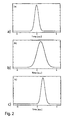
- Such a pulse as an input signal is in FIG. 2a shown. It is transmitted via the circulator 5 to the adjustable attenuator 6.
- the desired bandwidth of the pump laser 3 can be adjusted via a direct modulation with a noise signal.
- Optical amplification can be achieved by an Erbium-doped fiber amplifier ("EDFA").
- EDFA Erbium-doped fiber amplifier
- the carrier frequency of the pump laser is set to be increased from the carrier frequency of the data signal by the Brillouin shift frequency.
- the glass fiber 2 serves as a Brillouin medium, so that depending on the pump power set via the optical amplifier 4, an amplification and phase shift of the data signal occurs.
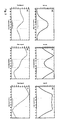
- diagrams d and e of FIG. 3 is the numerically calculated transfer function in the case of a 1.4 ns pulse, a Brillouin Bandwidth of 475 MHz and a pump power of 10 mW.
- the measuring points are corresponding in the FIG. 1 characterized. It can be seen that there is a strong decrease of the gain (3d) and nonlinearities in the phase shift (3e) in the edge region of the pulse spectrum.
- the output pulse of the first stage is, as can be seen from the diagram 2b, delayed and widened with respect to the input pulse 2a.
- a further coherent broadband pump laser 8 is provided, which is amplified by the optical amplifier 9 and in turn coupled via the circulator 10 against the propagation direction (arrow B) of the pulses in the glass fiber 7.
- the bandwidth of the pump laser 8 is greater than the signal bandwidth.
- This second stage is operated by means of the amplifier 9 in the saturation region of the system. Since the SBS system itself can be considered as an amplifier, high signal input powers or high pump powers make it possible to achieve saturation.
- the signal power is controlled via the attenuator 6, the pump power via the optical amplifier 9.
- the time delay is set not via the pump power but over the delay bandwidth, with a Increasing the bandwidth leads to a reduction of the time delay.
- the attenuator 11 is used to adjust the power of the output pulse to the interface 12. This may in turn be the input to an optical tracking system.
- the saturation of the second stage has two disadvantages: on the one hand, relatively high pump powers are required and, on the other hand, the time delay no longer depends linearly on the pump power and even decreases with increasing pump power. For this reason, in an advantageous embodiment, this stage is realized by superposition of two spectrally shifted SBS gain spectra, which simulate the saturation characteristic. Since the amplitude and phase response of the transfer function are interconnected by means of Kramers-Kronig relationships, the resulting gain function yields a phase function identical to the saturation case. In the FIG. 4 shown assembly replaced in this case, the module 8 in FIG. 1 ,
- the coherent pump laser 21 is modulated externally by means of the modulator 22.
- the signal generator 23 generates the necessary sine function whose frequency determines the distance of the respective gain spectrum to the zero point.
- the operating point of the modulator 22 is adjusted so that there is a carrier suppression and only the respective first sidebands arise.
- a Mach-Zehnder modulator can be used for the module 22 .
- the advantage of this system is that the time delay in the second stage can now be additionally set via the pump power and, in general, also lower pump powers are needed to compensate for the pulse broadening of the first stage.
- the superimposition of the two spectrally shifted SBS gain spectra is shown in the diagram of FIG. 4 shown.
Landscapes
- Physics & Mathematics (AREA)
- Electromagnetism (AREA)
- Engineering & Computer Science (AREA)
- Computer Networks & Wireless Communication (AREA)
- Signal Processing (AREA)
- Optical Communication System (AREA)
- Optical Modulation, Optical Deflection, Nonlinear Optics, Optical Demodulation, Optical Logic Elements (AREA)
Abstract
Description
- Die Erfindung betrifft ein Verfahren zur Verzögerung von optischen Signalen, die sich als Pulse in einem Wellenleiter in einer Vorwärtsrichtung ausbreiten, wobei in entgegengesetzter Richtung eine erste Pumpstrahlung in den Wellenleiter eingekoppelt wird, die eine stimulierte Brillouin Streuung (SBS) im Wellenlängenbereich der Pulse verursacht wird. Die Erfindung betrifft auch ein System zur Umsetzung des Verfahrens.
- Die gezielte Beeinflussung der Ausbreitungsgeschwindigkeit optischer Pulse eröffnet ein weites Feld für Anwendungen im Bereich optischer Kommunikationsnetze, der Datenverarbeitung, der nichtlinearen Optik und optischer Messsysteme. Dabei ist die Realisierung einstellbarer optischer Pufferspeicher ein großer Schritt in Richtung eines vollständig mit optischen Komponenten betriebenen Netzes. Bislang ist die Speicherung jedoch vorwiegend auf elektrische Komponenten beschränkt und geht immer mit einer optischelektrisch-optischen Wandlung einher. Dieser zusätzliche Aufwand begrenzt nicht nur die maximale Datenrate solcher Netze, sondern erhöht mit dem zusätzlichen Energieverbrauch auch den CO2-Anteil der Informations- und Kommunikationstechnologie.
- Ein Schritt hin zur Speicherung ist die Verzögerung optischer Pulse, für die es mehrere Ansätze gibt. Zum einen beruhen diese Ansätze auf der Laufzeit eines Signals in einem Wellenleiter oder Resonator und zum anderen auf der Erzeugung einer starken Dispersion. Der erste Ansatz ermöglicht lediglich feste Verzögerungszeiten, die einem Vielfachen der Pulsdauer entsprechen, während die Verzögerungszeit über den zweiten Ansatz stufenlos variiert werden kann, allerdings immer mit einer Verzerrung des Pulses verbunden ist. Eine einfache Methode zur Erzeugung einer starken künstlichen Dispersion ist die stimulierte Brillouin Streuung ("SBS"), die gegenüber anderen Ansätzen, basierend auf der stimulierten Raman Streuung oder elektromagnetisch induzierter Transparenz, entscheidende Vorteile besitzt: Zum einen sind nur wenige mW an Pumpleistung notwendig, um hohe Verzögerungszeiten zu erreichen. Zum anderen arbeitet die SBS im ganzen Transparenzbereich aller optischen Fasern und ermöglicht damit den Einsatz von Standard Equipment heutiger optischer TK- und Daten-Netze. Zudem ist die Verzögerungsbandbreite der SBS in weiten Bereichen flexibel einstellbar.
- Wie in allen dispersionsbasierten Systemen geht die Verzögerung jedoch immer mit einer Verzerrung der Pulse einher, die sich vor allem in einer Verbreiterung des Pulses äußert. Dabei begrenzen die Qualitäts-Anforderungen der jeweiligen Anwendung die zeitliche Pulsaufweitung und damit auch die Verzögerungszeit. Die Verbreiterung selbst hat zwei Ursachen: Zum einen führt das Bandpassverhalten des SBS Systems zu einer spektralen Begrenzung des Pulses und zum anderen wird die Phase des Pulses vor allem am spektralen Rand durch Nichtlinearitäten stark verzerrt.
- Bisherige Ansätze zur Vermeidung der Puls-Verbreiterung bei hoher Zeitverzögerung beruhen vor allem auf einer speziellen Anpassung des Verzögerungsspektrums. Dabei ist die Zeitverzögerung selbst proportional zur Pumpleistung und umgekehrt proportional zur Verzögerungsbandbreite. Höhere Pumpleistungen können die Erhöhung der Verzögerungsbandbreite nur bedingt ausgleichen, da Sättigungseffekte in einem SBS System die maximale Verzögerungszeit begrenzen. Abhilfe schafft eine Kaskadierung mehrerer Systeme. So wurde beispielsweise mit Hilfe eines 4-stufigen Systems eine Verzögerung von 3,8 Bit erreicht. Jedoch addiert sich auch eine geringe Pulsverzerrung von Stufe zu Stufe, was in dem Fall zu einer Verbreiterung auf das 2,55-fache des Eingangspulses führte. Auch eine spezielle Anpassung des Verzögerungsspektrums führt letztendlich maximal zu einer Optimierung des jeweiligen Systems, wobei die Pulsverbreiterung auch hier nicht vollständig vermieden werden kann.
- In dem Artikel von A. Wiatrek et al., "Zero-broadening measurement in Brillouin based slow-light delays", Optics Express, Vol. 17, No. 2, S. 797 - 802, Jan. 2009, ist offenbart, dass es in einem nichtlinearen System möglich ist, einen Puls zu verzögern ohne ihn zeitlich zu verbreitern. Diese Verzögerung führt jedoch zu einer Verzerrung der Pulsform. Für Einzelpulse, beispielsweise in messtechnischen Anwendungen, ist die reine Erhaltung der Pulsdauer bereits ausreichend. In Datennetzen führt die zusätzliche Pulsverzerrung jedoch zu unerwünschten Bitfehlern und damit zu einer signifikanten Reduktion der Systemperformance.
- Aufgabe der vorliegenden Erfindung ist es nunmehr, ein technisch einfach umsetzendes Verfahren und ein für die Umsetzung geeignetes optisches System zu schaffen, mit dem es möglich ist, Einzelpulse oder Pulse eines Datenstroms möglichst verzerrungsfrei zu verzögern, sodass Pulsform und Pulsbreite erhalten bleiben.
- Diese Aufgaben werden durch das Verfahren mit den kennzeichnenden Merkmalen des Anspruch 1 und das optische System nach Anspruch 7 gelöst. Besondere Ausführungsformen sind in den jeweiligen Unteransprüchen genannt.
- Der Kerngedanke der Erfindung liegt darin, innerhalb eines Übertragungssystems zwei Schritte oder "Stufen" vorzusehen, wobei der erste Schritt in einer konventionellen SBS-basierten Verzögerung der Pulse bewirkt, während im zweiten Schritt ein entgegenläufiges Übertragungsverhalten innerhalb des Systems realisiert wird. Wegen des gegensätzlichen Übertragungsverhaltens entsteht in Summe ein lineares Gesamtsystem. Der wesentliche Grundgedanke der Erfindung liegt somit in der Erzeugung eines vollständig linearen Filtersystems zur verzerrungsfreien Verzögerung optischer Pulse mittels eines zweistufigen Systems, bei dem sich beide Stufen mit entgegenläufigem Übertragungsverhalten zu einem linearen Gesamtsystem ergänzen. Durch ein solches erfindungsgemäßes Vorgehen wird eine zumindest nahezu verzerrungsfreie Verzögerung realisiert, so dass der Einsatz derartiger "Slow-Light" Systeme in Daten- und Kommunikationsnetzen möglich wird.
- Der erfindungsgemäße Gedanke beruht auf der Erkenntnis, dass gedämpfte Pulsanteile am Rand des Spektrums stärker verstärkt werden als Anteile im Zentrum des Pulses. Dieser Effekt wirkt der spektralen Begrenzung durch die erste Verzögerungsstufe entgegen. Da die Beeinflussung des Pulsspektrums und der Pulsphase durch das SBS System in einem direkten Zusammenhang stehen, wie die Kramers-Kronig Beziehungen besagen, kommt es im zweiten Schritt zu einer zusätzlichen Linearisierung der Pulsphase, was den beiden Ursachen der Verbreiterung entgegen wirkt. Darüber hinaus wird der Puls auch in diesem zweiten Schritt verzögert. Durch ein Kaskadieren solcher Systeme können im Prinzip beliebige Verzögerungen ohne zusätzliche Pulsverbreiterung und Pulsverzerrung erreicht werden.
- Zur Realisierung des zweiten Schrittes, respektive der zweiten Stufe, werden zwei Alternativen vorgestellt. Die erste basiert auf einem gesättigten System, wie es auch in dem oben genannten dem Artikel von A. Wiatrek et al. beschrieben wird. Demnach werden aufgrund der Sättigung leistungsstarke Spektrallinien weniger verstärkt als schwache. Im Gegensatz zu der Offenbarung in dem Artikel wird jedoch der Sättigungsgrad zusätzlich über die Leistung des Eingangssignals gezielt eingestellt, insbesondere durch eine variable Dämpfung zwischen den beiden System-Stufen. Der zweite Ansatz nutzt ein ungesättigtes lineares System, in dem das Übertragungsverhalten durch Überlagerung zweier spektral verschobener Verzögerungsbandbreiten gezielt nachgebildet wird.
- Insgesamt nutzt das System den nichtlinearen optischen Effekt der stimulierten Brillouin Streuung (SBS), bei dem es zur Wechselwirkung des Lichtes eines Pumplasers mit dem Ausbreitungsmedium des Lichtleiters, insbesondere in der hier eingesetzten Glasfaser, kommt. Bei der SBS führt die örtliche Änderung der Pumpfeldstärke zu einer Änderung der Dichte im Material, die den lokalen Brechungsindex beeinflusst. Die entstehende Dichtemodulationswelle erzeugt ein Brechnungsindexgitter und bewegt sich mit Schallgeschwindigkeit im Medium in Richtung der Pumpwelle. Aufgrund der Relativgeschwindigkeit beider Wellen und des Dopplereffektes kommt es zu einer Abwärtsverschiebung der Frequenz der zurückgestreuten Anteile der Pumpwelle ("Brillouin Verschiebungsfrequenz"). Die Höhe der Brillouin Verschiebungsfrequenz ist abhängig vom Material des Ausbreitungsmediums und beträgt in der verwendeten Standard Einmoden Glasfaser rund 11 GHz bei einer Pumpwellenlänge um 1550 nm. Wird nun die Pumpwelle in Gegenrichtung der Signalwelle im Frequenzabstand der Brillouin-Verschiebungsfrequenz eingekoppelt, so wird der Pumpwelle durch den Prozess Energie entzogen und es kommt zum exponentiellen Anwachsen der Leistung der Signalwelle und damit zu einem Verstärkungsprozess, der durch die Pumpleistung selbst begrenzt wird ("Sättigung").
- Neben der Verstärkung kommt es in Abhängigkeit von der SBS aber auch zu einer Änderung der Phase der Signalwelle. Der Zusammenhang zwischen Verstärkung und Phasenänderung wird durch die Kramers-Kronig Beziehungen beschrieben und führt im Fall der SBS zu einer Verzögerung des Signals ("Slow-Light"). Die Bandbreite des Verstärkungs- und Verzögerungsspektrums entsteht durch Faltung des Pumpspektrums mit dem materialabhängigen natürlichen Brillouin-Spektrum. Unter der Voraussetzung einer schmalbandigen Pumpwelle hat das entstehende Spektrum in der verwendeten Glasfaser eine Größe von etwa 30 MHz. Eine Erweiterung wird auf einfache Weise durch direkte Modulation des Pumplasers mit einem Rauschsignal erreicht, mit der eine Verbreiterung des Pumplaserspektrums erzielt wird.
- Ein Puls, dessen Spektrum sich innerhalb der SBS Bandbreite befindet, wird entsprechend verzögert, wobei die Pulsverzögerung im linearen Arbeitsbereich direkt proportional zur Pumpleistung und indirekt proportional zur Verzögerungsbandbreite ist. Die Verzerrung oder Verbreiterung des Pulses hat zwei Ursachen: Das ist zum einen die geringere Verstärkung respektive Dämpfung der Flanken des Pulsspektrums. Die Fourier-Transformation zeigt, dass eine Verkleinerung der spektralen Breite zu einer Vergrößerung der zeitlichen Breite führt. Die zweite Ursache liegt im nichtlinearen Phasenverlauf im Randbereich des Verzögerungsspektrums. Eine Verbreiterung dieses Spektrums minimiert einerseits die Verzerrungen, führt aber aufgrund der o.g. Proportionalität zu einer Verminderung der Zeitverzögerung. Diese kann in dem Rahmen durch eine Erhöhung der Pumpleistung ausgeglichen werden, bis es bei höheren Pumpleistungen zur Sättigung des Prozesses kommt ("Pumpauszehrung").
- Die Pulsverbreiterung wird durch ein erfindungsgemäß zweistufiges System verhindert. Die erste Stufe besteht aus dem beschriebenen herkömmlichen SBS-basierten System, das den Puls, wie erläutert, verbreitert. Die Charakteristik der zweiten Stufe wird genau umgekehrt zur ersten so eingestellt, dass es zu einer Umkehrung der Verbreiterung respektive zu einer Pulskompression und zusätzlich zu einer erhöhten Zeitverzögerung kommt. Eine solche Charakteristik kann durch eine herbeigeführte Sättigung der zweiten Stufe erreicht werden, mit der das Zentrum des Pulsspektrums viel weniger verstärkt wird als der Rand. Eine zweite Möglichkeit besteht in der Überlagerung zweier spektral verschobener SBS Gewinnspektren zur Nachbildung eines solchen Verstärkungsverhaltens. Die Addition der Charakteristika beider Stufen führt insgesamt zu einem linearen Gesamtsystem, das Pulse unter Erhaltung von Form und zeitlicher Breite verzögert.
- Der wesentliche Vorteil der erfindungsgemäßen Verfahrensweise ist das Erreichen eines verzerrungsfrei arbeitenden Systems zur Verzögerung optischer Pulse, das vollständig optisch kontrolliert wird. Vorteilhaft ist, dass sich das System mit Standardkomponenten optischer Telekommunikationsnetze einfach realisieren lässt. Diese Komponenten können preiswert in hohen Stückzahlen hergestellt werden. Der nichtlineare Effekt der SBS tritt in allen Glasfasern und in deren kompletten Transparenzbereich auf. Daher kann das System leicht an die jeweiligen Netzgegebenheiten angepasst werden. Zudem kann zur Realisierung der ersten Stufe die ankommende Faser eines Kommunikationssystems als Brillouin-Medium genutzt werden.
- Nachfolgend wird die Erfindung anhand der
Figuren 1 bis 4 näher erläutert. Es zeigen: - Figur 1:
- den Aufbau eines erfindungsgemäßen Systems
- Figur 2:
- Pulsformen an ausgewählten Stellen des Systems,
- Figur 3:
- Filterspektren an ausgewählten Messpunkten des Systems und
- Figur 4:
- eine alternative Realisierung der zweiten Stufe durch zwei überlagerte SBS Gewinnspektren.
- Nach
Figur 1 führt die Signalquelle 1 dem System das Datensignal in Form zu verzögernder Pulse zu, wobei die Signalquelle insbesondere die Schnittstelle zu einem Kommunikationsnetz ist, so dass die anschließende Glasfaser 2 bereits Bestandteil des Datenübertragungssystems sein kann. Das System weist einen kohärenten breitbandigen Pumplaser 3 auf, der durch einen optischen Verstärker 4 verstärkt wird und über den Zirkulator 5 entgegen der Ausbreitungsrichtung der Pulse (Pfeil A) in die Glasfaser 2 eingekoppelt wird. Ein solcher Puls als Eingangssignal ist inFigur 2a dargestellt. Er wird über den Zirkulator 5 zum einstellbaren Dämpfungsglied 6 übertragen. - Die gewünschte Bandbreite des Pumplasers 3 kann über eine direkte Modulation mit einem Rauschsignal eingestellt werden. Eine optische Verstärkung kann durch einen Erbium-dotierten Faser Verstärker ("EDFA") erreicht werden. Die Trägerfrequenz des Pumplasers wird so eingestellt, dass sie gegenüber der Trägerfrequenz des Datensignals um die Brillouin Verschiebungsfrequenz erhöht ist. Die Glasfaser 2 dient als Brillouin-Medium, sodass es abhängig von der über den optischen Verstärker 4 eingestellten Pumpleistung zu einer Verstärkung und Phasenverschiebung des Datensignals kommt.
- In den Diagrammen d und e der
Figur 3 ist die in diesem Fall numerisch berechnete Übertragungsfunktion im Fall eines 1.4 ns-Pulses, einer Brillouin - Bandbreite von 475 MHz und einer Pumpleistung von 10 mW dargestellt. Die Messpunkte sind entsprechend in derFigur 1 gekennzeichnet. Es ist ersichtlich, dass es im Randbereich des Pulsspektrums zu einer starken Abnahme der Verstärkung (3d) und Nichtlinearitäten in der Phasenverschiebung (3e) kommt. Der Ausgangspuls der ersten Stufe ist, wie aus dem Diagramm 2b ersichtlich, gegenüber dem Eingangspuls 2a verzögert und verbreitert. - Im System ist im Rahmen der zweiten Stufe ein weiterer kohärenter breitbandiger Pumplaser 8 vorgesehen, der durch den optischen Verstärker 9 verstärkt und über den Zirkulator 10 wiederum entgegen der Ausbreitungsrichtung (Pfeil B) der Pulse in die Glasfaser 7 eingekoppelt wird. Die Bandbreite des Pumplasers 8 ist größer als die Signalbandbreite. Diese zweite Stufe wird mittels des Verstärkers 9 im Sättigungsbereich des Systems betrieben. Da das SBS System selbst als ein Verstärker angesehen werden kann, ist es durch hohe Signaleingangsleistungen oder durch hohe Pumpleistungen möglich, eine Sättigung zu erreichen. Die Signalleistung wird über das Dämpfungsglied 6, die Pumpleistung über den optischen Verstärker 9 geregelt.
- In den Diagrammen f und g der
Figur 3 ist die - wiederum numerisch berechnete - Übertragungsfunktion für den Ausgangspuls der ersten Stufe bei einer Brillouin-Bandbreite von 960 MHz, einer Signaleingangsdämpfung von 10 dB und einer Pumpleistung von 20 mW abgebildet. Wie ersichtlich, ist das Übertragungsverhalten bezüglich der Amplitude und der Phase umgekehrt zur ersten Stufe. Der spektrale Randbereich wird gegenüber dem Zentrum angehoben und verzögert. Über den Zirkulator 10 wird das Signal zum Dämpfungsglied 11 geführt. Die Summe der Übertragungsfunktionen beider Stufen führt zu einer zumindest nahezu linearen Gesamtfunktion, also zu einer gleichmäßigen Verstärkung und einem linear fallenden Phasengang (Diagramme (h) und (i) derFigur 3 ). Somit entspricht der Ausgangspuls des Gesamtsystems dem verzögerten Eingangspuls. - Aufgrund der Sättigung der zweiten Stufe, wird die Zeitverzögerung nicht über die Pumpleistung, sondern über die Verzögerungsbandbreite eingestellt, wobei eine Vergrößerung der Bandbreite zu einer Verminderung der Zeitverzögerung führt. Das Dämpfungsglied 11 dient der Leistungsanpassung des Ausgangspulses an die Schnittstelle 12. Diese kann wiederum der Eingang zu einem optischen Folgesystem sein.
- Die Sättigung der zweiten Stufe birgt zwei Nachteile: Zum einen sind relativ hohe Pumpleistungen erforderlich und zum anderen ist die Zeitverzögerung nicht mehr linear von der Pumpleistung abhängig und nimmt mit steigender Pumpleistung sogar ab. Aus diesem Grund wird diese Stufe in einer vorteilhaften Ausführungsform durch Überlagerung zweier spektral verschobener SBS Gewinnspektren realisiert, welche die Sättigungscharakteristik nachbilden. Da Amplituden- und Phasengang der Übertragungsfunktion mittels Kramers-Kronig Beziehungen miteinander verbunden sind, ergibt die so entstehende Verstärkungsfunktion eine zum Sättigungsfall identische Phasenfunktion. Die in
Figur 4 dargestellte Baugruppe ersetzt in diesem Fall das Modul 8 inFigur 1 . - Dabei wird der kohärente Pumplaser 21 mittels des Modulators 22 extern moduliert. Der Signalgenerator 23 erzeugt die notwendige Sinusfunktion, deren Frequenz den Abstand des jeweiligen Gewinnspektrums zum Nullpunkt festlegt. Der Arbeitspunkt des Modulators 22 wird so eingestellt, dass es zu einer Trägerunterdrückung kommt und nur die jeweils ersten Seitenbänder entstehen. Für das Modul 22 kann ein Mach-Zehnder Modulator zum Einsatz kommen. Vorteil dieses Systems ist, dass die Zeitverzögerung in der zweiten Stufe nun zusätzlich über die Pumpleistung eingestellt werden kann und im Allgemeinen auch niedrigere Pumpleistungen benötigt werden, um die Pulsverbreiterung der ersten Stufe zu kompensieren. Die Überlagerung der beiden spektral verschobenen SBS Gewinnspektren ist in dem Diagramm der
Figur 4 gezeigt.
Claims (11)
- Verfahren zur Verzögerung von optischen Signalen, die sich als Pulse in einem Wellenleiter (2) in einer Vorwärtsrichtung ausbreiten, wobei in einer ersten Stufe eine erste Pumpstrahlung (3) entgegen der Ausbreitungsrichtung in den Wellenleiter (2) eingekoppelt wird, die stimulierte Brillouin Streuung ("SBS") im Wellenlängenbereich der Pulse verursacht und damit ein in einer Verzögerung der Pulse resultierendes Übertragungsverhalten im Wellenleiter bewirkt,
dadurch gekennzeichnet,
dass in einer nachfolgenden Stufe durch Einkopplung einer zweiten Pumpstrahlung (8), die in ihrer Charakteristik eingestellt ist und entgegen der Ausbreitungsrichtung der durch die erste Pumpstrahlung (3) modifizierten Pulse in den Wellenleiter (7) eingekoppelt wird, ein gegenläufiges Übertragungsverhalten im Wellenleiter (7) bewirkt wird, wobei aus der Abfolge der beiden Stufen ein insgesamt lineares Verhalten des Gesamtsystems resultiert, das zu einer Verzögerung optischer Pulse führt. - Verfahren nach Anspruch 1,
dadurch gekennzeichnet,
dass die Charakteristik der zweiten Stufe derart eingestellt ist, dass gedämpfte Pulsanteile am Rand des Spektrums stärker verstärkt werden als Anteile im Zentrum des Pulses. - Verfahren nach Anspruch 1 oder 2,
dadurch gekennzeichnet,
dass zum Erreichen größerer Verzögerungszeiten Systeme mit einer Abfolge einer solchen ersten und zweiten Stufe kaskadiert werden. - Verfahren nach einem der vorherigen Ansprüche,
dadurch gekennzeichnet,
dass die Leistung des die zweite Stufe erreichenden Eingangspulses, insbesondere durch eine variable Dämpfung zwischen den beiden Stufen, eingestellt wird. - Verfahren nach einem der vorherigen Ansprüche,
dadurch gekennzeichnet,
dass die zweite Stufe als ungesättigtes lineares System ausgebildet wird, in dem das Übertragungsverhalten durch Überlagerung zweier spektral verschobener Verzögerungsbandbreiten gezielt nachgebildet wird. - System zur Umsetzung des Verfahrens nach einem der vorherigen Ansprüche, aufweisend einen Wellenleiter (2,7), in dem sich Signalpulse in Vorwärtsrichtung ausbreiten, wobei in einer ersten Stufe des Systems eine erste Quelle (3) zur Erzeugung einer ersten Pumpstrahlung vorgesehen ist, wobei Mittel (5) zur Einkopplung der Pumpstrahlung in den Wellenleiter (3) entgegen der sich in Vorwärtsrichtung ausbreitenden Signalpulse vorgesehen sind, wobei ein Mittel zur Auskopplung (5) der in Vorwärtsrichtung propagierenden und durch SBS verzögerten Signalpulse vorgesehen ist,
gekennzeichnet durch
eine zweite Stufe aufweisend eine zweite Quelle (8) zur Erzeugung einer zweiten Pumpstrahlung, die über ein zweites Mittel (10) zur Einkopplung in den Wellenleiter (2,7) entgegen der sich in Vorwärtsrichtung verzögerten Signalpulse einkoppelbar ist, wobei die Bandbreite der zweiten Pumpstrahlung größer als die Bandbreite der Signalpulse ist. - System nach Anspruch 6,
dadurch gekennzeichnet,
dass die zweite Stufe mittels eines Verstärkers im Sättigungsbereich des Systems betrieben wird. - System nach Anspruch 7,
gekennzeichnet durch
einen optischen Verstärker (9) zur Regelung der Pumpleistung der zweiten Quelle (8). - System nach Anspruch 6,
dadurch gekennzeichnet,
dass die zweite Stufe einen kohärenten Pumplaser (21) aufweist, der mittels des Modulators (22) moduliert wird, wobei ein Signalgenerator (23) eine Sinusfunktion erzeugt und wobei der Arbeitspunkt des Modulators (22) derart einstellbar ist, dass es zu einer Trägerunterdrückung kommt und nur die jeweils ersten Seitenbänder entstehen. - System nach einem der Ansprüche 6 bis 9,
gekennzeichnet durch
ein Dämpfungsglied (6) zur Modifikation der Signalleistung. - System nach einem der Ansprüche 6 bis 10,
gekennzeichnet durch
ein Dämpfungsglied (11) zur Leistungsanpassung des Ausgangspulses an eine das System abschließende Schnittstelle (12).
Priority Applications (1)
| Application Number | Priority Date | Filing Date | Title |
|---|---|---|---|
| PL10008263T PL2299611T3 (pl) | 2009-09-18 | 2010-08-07 | Kontrolowane optycznie i wolne od zakłóceń opóźnianie impulsów optycznych |
Applications Claiming Priority (1)
| Application Number | Priority Date | Filing Date | Title |
|---|---|---|---|
| DE102009041849A DE102009041849A1 (de) | 2009-09-18 | 2009-09-18 | Optisch kontrollierte und verzerrungsfreie Verzögerung optischer Pulse |
Publications (2)
| Publication Number | Publication Date |
|---|---|
| EP2299611A1 true EP2299611A1 (de) | 2011-03-23 |
| EP2299611B1 EP2299611B1 (de) | 2013-11-20 |
Family
ID=43446456
Family Applications (1)
| Application Number | Title | Priority Date | Filing Date |
|---|---|---|---|
| EP10008263.5A Active EP2299611B1 (de) | 2009-09-18 | 2010-08-07 | Optisch kontrollierte und verzerrungsfreie Verzögerung optischer Pulse |
Country Status (4)
| Country | Link |
|---|---|
| EP (1) | EP2299611B1 (de) |
| DE (1) | DE102009041849A1 (de) |
| ES (1) | ES2439769T3 (de) |
| PL (1) | PL2299611T3 (de) |
Citations (2)
| Publication number | Priority date | Publication date | Assignee | Title |
|---|---|---|---|---|
| JP2009063951A (ja) * | 2007-09-10 | 2009-03-26 | Nippon Telegr & Teleph Corp <Ntt> | 光パルス速度制御装置及び光パルスの速度制御方法 |
| JP2009204660A (ja) * | 2008-02-26 | 2009-09-10 | Nippon Telegr & Teleph Corp <Ntt> | 光パルス速度制御装置及び光パルスの速度制御方法 |
-
2009
- 2009-09-18 DE DE102009041849A patent/DE102009041849A1/de not_active Withdrawn
-
2010
- 2010-08-07 PL PL10008263T patent/PL2299611T3/pl unknown
- 2010-08-07 EP EP10008263.5A patent/EP2299611B1/de active Active
- 2010-08-07 ES ES10008263.5T patent/ES2439769T3/es active Active
Patent Citations (2)
| Publication number | Priority date | Publication date | Assignee | Title |
|---|---|---|---|---|
| JP2009063951A (ja) * | 2007-09-10 | 2009-03-26 | Nippon Telegr & Teleph Corp <Ntt> | 光パルス速度制御装置及び光パルスの速度制御方法 |
| JP2009204660A (ja) * | 2008-02-26 | 2009-09-10 | Nippon Telegr & Teleph Corp <Ntt> | 光パルス速度制御装置及び光パルスの速度制御方法 |
Non-Patent Citations (2)
| Title |
|---|
| A. WIATREK ET AL.: "Zero-broadening measurement in Brillouin based slow-light delays", OPTICS EXPRESS, vol. 17, no. 2, January 2009 (2009-01-01), pages 797 - 802 |
| SCHNEIDER T ET AL: "Distortion reduction in cascaded slow light delays", ELECTRONICS LETTERS, IEE STEVENAGE, GB, vol. 42, no. 19, 14 September 2006 (2006-09-14), pages 1110 - 1112, XP006027441, ISSN: 0013-5194, DOI: 10.1049/EL:20062235 * |
Also Published As
| Publication number | Publication date |
|---|---|
| ES2439769T3 (es) | 2014-01-24 |
| PL2299611T3 (pl) | 2014-04-30 |
| DE102009041849A1 (de) | 2011-03-24 |
| EP2299611B1 (de) | 2013-11-20 |
Similar Documents
| Publication | Publication Date | Title |
|---|---|---|
| DE69510438T2 (de) | Optischer Hochleistungssender mit hochgesättigtem Verstärker zur Unterdrückung der Restamplitudenmodulation | |
| DE69320101T2 (de) | Unterdrücken von Rauschen und Verzerrungen in einem Lichtwellenleitersystem | |
| DE69811801T2 (de) | Überttragungssystem mit Querphasen- und/oder Eigenphasenmodulationskompensierung | |
| DE19549868B4 (de) | Optische Impulsverstärkung unter Verwendung chirp-modulierter Bragg-Gitter | |
| DE69825401T2 (de) | Optischer Pulskompressor für optische Kommunikationssysteme | |
| DE69603141T2 (de) | Dispersionskompensation | |
| DE69529305T2 (de) | Datenkodierter optischer Impulsgeber | |
| DE3785858T2 (de) | Soliton-lichtwellenleiteruebertragungssystem. | |
| DE69632720T2 (de) | Mehrfrequenzphasenmodulation für lichtwellenübertragungssystem | |
| DE69225096T2 (de) | Verzerrungsarme optische Vorrichtung mit Schwelle | |
| DE69623219T2 (de) | Vorrichtung und Verfahren zur Veränderung der Spektraleigenschaften von optischen Signalen | |
| DE19619780A1 (de) | Optisches Übertragungssystem, optisches Transmissionsmodul, und optischer Modulator | |
| DE69209633T2 (de) | Rauscharmer optischer Verstärker mit einem hinter dem Verstärker angeordneten Verlustelement | |
| EP0835542A1 (de) | Wellenlängen-konverter | |
| WO2022135910A1 (de) | Passiv modengekoppelter faseroszillator und lasereinrichtung mit einem solchen faseroszillator | |
| DE69022151T2 (de) | Halbleiterlaserverstärkereinheit hoher Verstärkung. | |
| WO2022135911A1 (de) | Passiv modengekoppelter faseroszillator und lasereinrichtung mit einem solchen faseroszillator | |
| EP1271811B1 (de) | Verfahren und Vorrichtung zur Verstärkung von WDM Signalen mittels des stimulierten Brillouin-Streuprozess | |
| EP2111677B1 (de) | Beeinflussung der ausbreitungsgeschwindigkeit von signalen in lichtleitern | |
| EP2218196B1 (de) | Kaskadierte seitenbanderzeugung mit sbs dispersionskontrolle der signalpropagation | |
| DE10046941A1 (de) | Verfahren und Anordnung zur Verbesserung der Signalqualität eines modulierten optischen Übertragungssignals | |
| EP2299611B1 (de) | Optisch kontrollierte und verzerrungsfreie Verzögerung optischer Pulse | |
| EP2491725B1 (de) | Verfahren zur verzögerung von optischen pulsen | |
| DE69900572T2 (de) | Anordnung zum Inline-Regenerieren eines optischen Solitonsignals durch synchrone Modulation dieser Solitonen und Übertragungssystem mit einer derartigen Vorrichtung | |
| DE102005054379B4 (de) | Verfahren und System zur Verstärkung von Licht in optischen Fasern |
Legal Events
| Date | Code | Title | Description |
|---|---|---|---|
| PUAI | Public reference made under article 153(3) epc to a published international application that has entered the european phase |
Free format text: ORIGINAL CODE: 0009012 |
|
| AK | Designated contracting states |
Kind code of ref document: A1 Designated state(s): AL AT BE BG CH CY CZ DE DK EE ES FI FR GB GR HR HU IE IS IT LI LT LU LV MC MK MT NL NO PL PT RO SE SI SK SM TR |
|
| AX | Request for extension of the european patent |
Extension state: BA ME RS |
|
| 17P | Request for examination filed |
Effective date: 20110923 |
|
| 17Q | First examination report despatched |
Effective date: 20130402 |
|
| REG | Reference to a national code |
Ref country code: DE Ref legal event code: R079 Ref document number: 502010005402 Country of ref document: DE Free format text: PREVIOUS MAIN CLASS: H04B0010170000 Ipc: H04B0010253100 |
|
| RIC1 | Information provided on ipc code assigned before grant |
Ipc: H04B 10/2531 20130101AFI20130522BHEP |
|
| GRAP | Despatch of communication of intention to grant a patent |
Free format text: ORIGINAL CODE: EPIDOSNIGR1 |
|
| INTG | Intention to grant announced |
Effective date: 20130708 |
|
| GRAS | Grant fee paid |
Free format text: ORIGINAL CODE: EPIDOSNIGR3 |
|
| GRAA | (expected) grant |
Free format text: ORIGINAL CODE: 0009210 |
|
| AK | Designated contracting states |
Kind code of ref document: B1 Designated state(s): AL AT BE BG CH CY CZ DE DK EE ES FI FR GB GR HR HU IE IS IT LI LT LU LV MC MK MT NL NO PL PT RO SE SI SK SM TR |
|
| REG | Reference to a national code |
Ref country code: GB Ref legal event code: FG4D Free format text: NOT ENGLISH |
|
| REG | Reference to a national code |
Ref country code: CH Ref legal event code: EP |
|
| REG | Reference to a national code |
Ref country code: AT Ref legal event code: REF Ref document number: 642160 Country of ref document: AT Kind code of ref document: T Effective date: 20131215 |
|
| REG | Reference to a national code |
Ref country code: IE Ref legal event code: FG4D Free format text: LANGUAGE OF EP DOCUMENT: GERMAN |
|
| REG | Reference to a national code |
Ref country code: DE Ref legal event code: R096 Ref document number: 502010005402 Country of ref document: DE Effective date: 20140116 |
|
| REG | Reference to a national code |
Ref country code: ES Ref legal event code: FG2A Ref document number: 2439769 Country of ref document: ES Kind code of ref document: T3 Effective date: 20140124 |
|
| REG | Reference to a national code |
Ref country code: NL Ref legal event code: VDEP Effective date: 20131120 |
|
| REG | Reference to a national code |
Ref country code: LT Ref legal event code: MG4D |
|
| PG25 | Lapsed in a contracting state [announced via postgrant information from national office to epo] |
Ref country code: FI Free format text: LAPSE BECAUSE OF FAILURE TO SUBMIT A TRANSLATION OF THE DESCRIPTION OR TO PAY THE FEE WITHIN THE PRESCRIBED TIME-LIMIT Effective date: 20131120 Ref country code: NO Free format text: LAPSE BECAUSE OF FAILURE TO SUBMIT A TRANSLATION OF THE DESCRIPTION OR TO PAY THE FEE WITHIN THE PRESCRIBED TIME-LIMIT Effective date: 20140220 Ref country code: LT Free format text: LAPSE BECAUSE OF FAILURE TO SUBMIT A TRANSLATION OF THE DESCRIPTION OR TO PAY THE FEE WITHIN THE PRESCRIBED TIME-LIMIT Effective date: 20131120 Ref country code: SE Free format text: LAPSE BECAUSE OF FAILURE TO SUBMIT A TRANSLATION OF THE DESCRIPTION OR TO PAY THE FEE WITHIN THE PRESCRIBED TIME-LIMIT Effective date: 20131120 Ref country code: HR Free format text: LAPSE BECAUSE OF FAILURE TO SUBMIT A TRANSLATION OF THE DESCRIPTION OR TO PAY THE FEE WITHIN THE PRESCRIBED TIME-LIMIT Effective date: 20131120 Ref country code: IS Free format text: LAPSE BECAUSE OF FAILURE TO SUBMIT A TRANSLATION OF THE DESCRIPTION OR TO PAY THE FEE WITHIN THE PRESCRIBED TIME-LIMIT Effective date: 20140320 Ref country code: NL Free format text: LAPSE BECAUSE OF FAILURE TO SUBMIT A TRANSLATION OF THE DESCRIPTION OR TO PAY THE FEE WITHIN THE PRESCRIBED TIME-LIMIT Effective date: 20131120 |
|
| REG | Reference to a national code |
Ref country code: PL Ref legal event code: T3 |
|
| PG25 | Lapsed in a contracting state [announced via postgrant information from national office to epo] |
Ref country code: LV Free format text: LAPSE BECAUSE OF FAILURE TO SUBMIT A TRANSLATION OF THE DESCRIPTION OR TO PAY THE FEE WITHIN THE PRESCRIBED TIME-LIMIT Effective date: 20131120 |
|
| PG25 | Lapsed in a contracting state [announced via postgrant information from national office to epo] |
Ref country code: PT Free format text: LAPSE BECAUSE OF FAILURE TO SUBMIT A TRANSLATION OF THE DESCRIPTION OR TO PAY THE FEE WITHIN THE PRESCRIBED TIME-LIMIT Effective date: 20140320 |
|
| PG25 | Lapsed in a contracting state [announced via postgrant information from national office to epo] |
Ref country code: EE Free format text: LAPSE BECAUSE OF FAILURE TO SUBMIT A TRANSLATION OF THE DESCRIPTION OR TO PAY THE FEE WITHIN THE PRESCRIBED TIME-LIMIT Effective date: 20131120 |
|
| REG | Reference to a national code |
Ref country code: DE Ref legal event code: R097 Ref document number: 502010005402 Country of ref document: DE |
|
| PG25 | Lapsed in a contracting state [announced via postgrant information from national office to epo] |
Ref country code: CZ Free format text: LAPSE BECAUSE OF FAILURE TO SUBMIT A TRANSLATION OF THE DESCRIPTION OR TO PAY THE FEE WITHIN THE PRESCRIBED TIME-LIMIT Effective date: 20131120 Ref country code: RO Free format text: LAPSE BECAUSE OF FAILURE TO SUBMIT A TRANSLATION OF THE DESCRIPTION OR TO PAY THE FEE WITHIN THE PRESCRIBED TIME-LIMIT Effective date: 20131120 Ref country code: SK Free format text: LAPSE BECAUSE OF FAILURE TO SUBMIT A TRANSLATION OF THE DESCRIPTION OR TO PAY THE FEE WITHIN THE PRESCRIBED TIME-LIMIT Effective date: 20131120 |
|
| PLBE | No opposition filed within time limit |
Free format text: ORIGINAL CODE: 0009261 |
|
| STAA | Information on the status of an ep patent application or granted ep patent |
Free format text: STATUS: NO OPPOSITION FILED WITHIN TIME LIMIT |
|
| PG25 | Lapsed in a contracting state [announced via postgrant information from national office to epo] |
Ref country code: DK Free format text: LAPSE BECAUSE OF FAILURE TO SUBMIT A TRANSLATION OF THE DESCRIPTION OR TO PAY THE FEE WITHIN THE PRESCRIBED TIME-LIMIT Effective date: 20131120 |
|
| 26N | No opposition filed |
Effective date: 20140821 |
|
| REG | Reference to a national code |
Ref country code: DE Ref legal event code: R097 Ref document number: 502010005402 Country of ref document: DE Effective date: 20140821 |
|
| PG25 | Lapsed in a contracting state [announced via postgrant information from national office to epo] |
Ref country code: SI Free format text: LAPSE BECAUSE OF FAILURE TO SUBMIT A TRANSLATION OF THE DESCRIPTION OR TO PAY THE FEE WITHIN THE PRESCRIBED TIME-LIMIT Effective date: 20131120 |
|
| PG25 | Lapsed in a contracting state [announced via postgrant information from national office to epo] |
Ref country code: LU Free format text: LAPSE BECAUSE OF FAILURE TO SUBMIT A TRANSLATION OF THE DESCRIPTION OR TO PAY THE FEE WITHIN THE PRESCRIBED TIME-LIMIT Effective date: 20140807 Ref country code: MC Free format text: LAPSE BECAUSE OF FAILURE TO SUBMIT A TRANSLATION OF THE DESCRIPTION OR TO PAY THE FEE WITHIN THE PRESCRIBED TIME-LIMIT Effective date: 20131120 |
|
| REG | Reference to a national code |
Ref country code: CH Ref legal event code: PL |
|
| PG25 | Lapsed in a contracting state [announced via postgrant information from national office to epo] |
Ref country code: CH Free format text: LAPSE BECAUSE OF NON-PAYMENT OF DUE FEES Effective date: 20140831 Ref country code: LI Free format text: LAPSE BECAUSE OF NON-PAYMENT OF DUE FEES Effective date: 20140831 Ref country code: BE Free format text: LAPSE BECAUSE OF NON-PAYMENT OF DUE FEES Effective date: 20140831 |
|
| REG | Reference to a national code |
Ref country code: IE Ref legal event code: MM4A |
|
| PG25 | Lapsed in a contracting state [announced via postgrant information from national office to epo] |
Ref country code: IE Free format text: LAPSE BECAUSE OF NON-PAYMENT OF DUE FEES Effective date: 20140807 |
|
| PG25 | Lapsed in a contracting state [announced via postgrant information from national office to epo] |
Ref country code: SM Free format text: LAPSE BECAUSE OF FAILURE TO SUBMIT A TRANSLATION OF THE DESCRIPTION OR TO PAY THE FEE WITHIN THE PRESCRIBED TIME-LIMIT Effective date: 20131120 |
|
| PG25 | Lapsed in a contracting state [announced via postgrant information from national office to epo] |
Ref country code: BG Free format text: LAPSE BECAUSE OF FAILURE TO SUBMIT A TRANSLATION OF THE DESCRIPTION OR TO PAY THE FEE WITHIN THE PRESCRIBED TIME-LIMIT Effective date: 20131120 Ref country code: MT Free format text: LAPSE BECAUSE OF FAILURE TO SUBMIT A TRANSLATION OF THE DESCRIPTION OR TO PAY THE FEE WITHIN THE PRESCRIBED TIME-LIMIT Effective date: 20131120 Ref country code: GR Free format text: LAPSE BECAUSE OF FAILURE TO SUBMIT A TRANSLATION OF THE DESCRIPTION OR TO PAY THE FEE WITHIN THE PRESCRIBED TIME-LIMIT Effective date: 20140221 Ref country code: CY Free format text: LAPSE BECAUSE OF FAILURE TO SUBMIT A TRANSLATION OF THE DESCRIPTION OR TO PAY THE FEE WITHIN THE PRESCRIBED TIME-LIMIT Effective date: 20131120 |
|
| PG25 | Lapsed in a contracting state [announced via postgrant information from national office to epo] |
Ref country code: TR Free format text: LAPSE BECAUSE OF FAILURE TO SUBMIT A TRANSLATION OF THE DESCRIPTION OR TO PAY THE FEE WITHIN THE PRESCRIBED TIME-LIMIT Effective date: 20131120 Ref country code: HU Free format text: LAPSE BECAUSE OF FAILURE TO SUBMIT A TRANSLATION OF THE DESCRIPTION OR TO PAY THE FEE WITHIN THE PRESCRIBED TIME-LIMIT; INVALID AB INITIO Effective date: 20100807 |
|
| REG | Reference to a national code |
Ref country code: FR Ref legal event code: PLFP Year of fee payment: 7 |
|
| REG | Reference to a national code |
Ref country code: AT Ref legal event code: MM01 Ref document number: 642160 Country of ref document: AT Kind code of ref document: T Effective date: 20150807 |
|
| PG25 | Lapsed in a contracting state [announced via postgrant information from national office to epo] |
Ref country code: AT Free format text: LAPSE BECAUSE OF NON-PAYMENT OF DUE FEES Effective date: 20150807 |
|
| REG | Reference to a national code |
Ref country code: FR Ref legal event code: PLFP Year of fee payment: 8 |
|
| PG25 | Lapsed in a contracting state [announced via postgrant information from national office to epo] |
Ref country code: MK Free format text: LAPSE BECAUSE OF FAILURE TO SUBMIT A TRANSLATION OF THE DESCRIPTION OR TO PAY THE FEE WITHIN THE PRESCRIBED TIME-LIMIT Effective date: 20131120 |
|
| REG | Reference to a national code |
Ref country code: FR Ref legal event code: PLFP Year of fee payment: 9 |
|
| PG25 | Lapsed in a contracting state [announced via postgrant information from national office to epo] |
Ref country code: AL Free format text: LAPSE BECAUSE OF FAILURE TO SUBMIT A TRANSLATION OF THE DESCRIPTION OR TO PAY THE FEE WITHIN THE PRESCRIBED TIME-LIMIT Effective date: 20131120 |
|
| PGFP | Annual fee paid to national office [announced via postgrant information from national office to epo] |
Ref country code: DE Payment date: 20240819 Year of fee payment: 15 |
|
| PGFP | Annual fee paid to national office [announced via postgrant information from national office to epo] |
Ref country code: GB Payment date: 20240822 Year of fee payment: 15 |
|
| PGFP | Annual fee paid to national office [announced via postgrant information from national office to epo] |
Ref country code: FR Payment date: 20240821 Year of fee payment: 15 |
|
| PGFP | Annual fee paid to national office [announced via postgrant information from national office to epo] |
Ref country code: ES Payment date: 20240918 Year of fee payment: 15 |
|
| PGFP | Annual fee paid to national office [announced via postgrant information from national office to epo] |
Ref country code: PL Payment date: 20240729 Year of fee payment: 15 |
|
| PGFP | Annual fee paid to national office [announced via postgrant information from national office to epo] |
Ref country code: IT Payment date: 20240830 Year of fee payment: 15 |
|
| REG | Reference to a national code |
Ref country code: DE Ref legal event code: R119 Ref document number: 502010005402 Country of ref document: DE |
|
| GBPC | Gb: european patent ceased through non-payment of renewal fee |
Effective date: 20250807 |