EP2299554B1 - A method for cutting off a power supply prior to open a cover and an apparatus thereof - Google Patents
A method for cutting off a power supply prior to open a cover and an apparatus thereof Download PDFInfo
- Publication number
- EP2299554B1 EP2299554B1 EP20090765325 EP09765325A EP2299554B1 EP 2299554 B1 EP2299554 B1 EP 2299554B1 EP 20090765325 EP20090765325 EP 20090765325 EP 09765325 A EP09765325 A EP 09765325A EP 2299554 B1 EP2299554 B1 EP 2299554B1
- Authority
- EP
- European Patent Office
- Prior art keywords
- bolt
- motion sensor
- lock
- casing
- cover
- Prior art date
- Legal status (The legal status is an assumption and is not a legal conclusion. Google has not performed a legal analysis and makes no representation as to the accuracy of the status listed.)
- Active
Links
Images
Classifications
-
- F—MECHANICAL ENGINEERING; LIGHTING; HEATING; WEAPONS; BLASTING
- F16—ENGINEERING ELEMENTS AND UNITS; GENERAL MEASURES FOR PRODUCING AND MAINTAINING EFFECTIVE FUNCTIONING OF MACHINES OR INSTALLATIONS; THERMAL INSULATION IN GENERAL
- F16P—SAFETY DEVICES IN GENERAL; SAFETY DEVICES FOR PRESSES
- F16P3/00—Safety devices acting in conjunction with the control or operation of a machine; Control arrangements requiring the simultaneous use of two or more parts of the body
- F16P3/08—Safety devices acting in conjunction with the control or operation of a machine; Control arrangements requiring the simultaneous use of two or more parts of the body in connection with the locking of doors, covers, guards, or like members giving access to moving machine parts
-
- G—PHYSICS
- G08—SIGNALLING
- G08B—SIGNALLING SYSTEMS, e.g. PERSONAL CALLING SYSTEMS; ORDER TELEGRAPHS; ALARM SYSTEMS
- G08B21/00—Alarms responsive to a single specified undesired or abnormal condition and not otherwise provided for
- G08B21/18—Status alarms
- G08B21/185—Electrical failure alarms
-
- E—FIXED CONSTRUCTIONS
- E05—LOCKS; KEYS; WINDOW OR DOOR FITTINGS; SAFES
- E05B—LOCKS; ACCESSORIES THEREFOR; HANDCUFFS
- E05B1/00—Knobs or handles for wings; Knobs, handles, or press buttons for locks or latches on wings
-
- G—PHYSICS
- G07—CHECKING-DEVICES
- G07C—TIME OR ATTENDANCE REGISTERS; REGISTERING OR INDICATING THE WORKING OF MACHINES; GENERATING RANDOM NUMBERS; VOTING OR LOTTERY APPARATUS; ARRANGEMENTS, SYSTEMS OR APPARATUS FOR CHECKING NOT PROVIDED FOR ELSEWHERE
- G07C1/00—Registering, indicating or recording the time of events or elapsed time, e.g. time-recorders for work people
-
- H—ELECTRICITY
- H01—ELECTRIC ELEMENTS
- H01H—ELECTRIC SWITCHES; RELAYS; SELECTORS; EMERGENCY PROTECTIVE DEVICES
- H01H9/00—Details of switching devices, not covered by groups H01H1/00 - H01H7/00
- H01H9/20—Interlocking, locking, or latching mechanisms
- H01H9/22—Interlocking, locking, or latching mechanisms for interlocking between casing, cover, or protective shutter and mechanism for operating contacts
Definitions
- the motion sensor 9 with the motion sensor rod 8 is provided inside a hole in an upper portion of the bolt casing with a lock 2.
- the motion sensor 9 is connected to the safety protecting and monitoring unit 10.
- a lower end of the motion sensor rod 8 is pressed against a bolt head of the bolt 5.
- the bolt 5 is jacketed with the distance sleeve 7.
- the distance sleeve 7 is cushioned with the spring washer 6 thereunder.
- the distance sleeve 7 is provided with an annular locking slot, and the annular locking slot is connected to the lock core 4.
Landscapes
- Engineering & Computer Science (AREA)
- General Engineering & Computer Science (AREA)
- Mechanical Engineering (AREA)
- Business, Economics & Management (AREA)
- Emergency Management (AREA)
- Physics & Mathematics (AREA)
- General Physics & Mathematics (AREA)
- Casings For Electric Apparatus (AREA)
- Burglar Alarm Systems (AREA)
- Emergency Alarm Devices (AREA)
- Operating, Guiding And Securing Of Roll- Type Closing Members (AREA)
Description
- The present invention relates to a power-off method and apparatus for cutting off a power supply for electrical equipments in coal mines and various flammable and explosive places, and more specifically, relates to a pre-cover-opening power-off method and apparatus.
- The Coal Mines Safety Regulations provide that, "live maintenance and movement of electrical equipments, cables and wires are prohibited underground". However, in practical operations, live maintenance frequently occurs due to a lack of the facilities guarantees, causing countless coal mine accidents. In order to solve this problem, Chinese Patent No.
200710010531.9 200520023343.6 DE 1703037 B1 and refers to a safety lock for a machine housing. - The present invention intends to provide a pre-cover-opening power-off method and apparatus, which can send out a signal to a safety protecting and monitoring unit to cut off the power supply and give out an alarm before screwing off a screw on a cover plate of an electrical equipment, to thereby solve the problems as to the accidents of gas explosion and casualties that are caused by live operation. The present invention is thus defined by the appended claims 1-22.
- The present invention is implemented with the following technical solution:
- A pre-cover-opening power-off method, comprising the steps of: (a) fixing a bolt casing to a bolt, (b) connecting a motion sensor to a safety protecting and monitoring unit in a wired or wireless manner, (c) activating the motion sensor to send out a command to permit power delivery for an electrical equipment to operate, and when the bolt casing is taken off, the motion sensor is activated to send out a command to cut off a power supply for the electrical equipment or give out an alarm. The step (a) of fixing the bolt casing to the bolt is realized in the following manner: operating a key and a lock core or a fastening screw to enter an annular locking slot of the bolt with a distance sleeve so as to fix the bolt casing, or fixing the bolt casing to the bolt through threaded connection, or fixing the bolt casing to the bolt by pinning, or locking the bolt casing to the bolt. The step (c) of activating the motion sensor is realized in the following manner: when the bolt casing is fixed to the bolt, a bolt head or the distance sleeve or an electrical equipment cover plate is pressed against a motion sensor rod, and a contact is closed or opened, whereby a signal is sent out to the safety protecting and monitoring unit; when the bolt casing is taken off, the motion sensor rod leaves the bolt head or the distance sleeve or the electrical equipment cover plate, and the contact is opened or closed, whereby a signal is sent out to the safety protecting and monitoring unit, or the motion sensor is activated to send out a signal to the safety protecting and monitoring unit when the key and the lock core are operated.
- A pre-cover-opening power-off apparatus with a lock, comprising an electrical equipment cover plate 1, a bolt casing with a lock 2, a
key 3, a lock core 4, abolt 5, amotion sensor 9, and a safety protecting andmonitoring unit 10. The electrical equipment cover plate 1 is connected to the bolt casing with a lock 2 by means of thebolt 5. Thekey 3 and the lock core 4 are provided inside a hole on one side of the bolt casing with a lock 2. Alocking screw 11 is provided inside a hole on the other side of the bolt casing with a lock 2. Themotion sensor 9 with amotion sensor rod 8 is provided inside a hole in an upper portion of the bolt casing with a lock 2. Themotion sensor 9 is connected to the safety protecting and monitoringunit 10. A lower end of themotion sensor rod 8 is pressed against a bolt head of thebolt 5. Thebolt 5 is jacketed with adistance sleeve 7. Thedistance sleeve 7 is cushioned with aspring washer 6 thereunder. Thedistance sleeve 7 is provided with an annular locking slot, and the annular locking slot is connected to the lock core 4. The bolt casing is a bolt casing with a lock or a bolt casing without a lock, or a frame or a pin that is mounted on the bolt and can block the screwing of the bolt. - As compared with the prior art, the present invention has the following beneficial effects: operators can be effectively prevented from live operations during equipment overhaul, and before opening the electrical equipment cover plate, a signal can be sent out to the safety protecting and monitoring unit, to cut off the power supply and give out an alarm, thereby realizing pre-cover-opening power-off. The present invention can be widely applied to electrical equipments at various flammable and explosive places such as coal mines and flammable and explosive workshops, for guaranteeing the safety of overhaul operators.
-
-
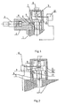
Fig. 1 illustrates schematically the structure of a pre-cover-opening power-off apparatus with a lock as described in Embodiment 1. -
Fig. 2 illustrates schematically the structure of a first type of pre-cover-opening power-off apparatus without a lock described in Embodiment 2. -
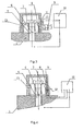
Fig. 3 illustrates schematically the structure of a second type of pre-cover-opening power-off apparatus without a lock described inEmbodiment 3. -
Fig. 4 illustrates schematically the structure of a third type of pre-cover-opening power-off apparatus without a lock described in Embodiment 4. - A detailed description of a pre-cover-opening power-off method is given below with reference to the four types of pre-cover-opening power-off apparatuses.
-
Fig. 1 shows a pre-cover-opening power-off apparatus with a lock, which comprises an electrical equipment cover plate 1, a bolt casing with a lock 2, akey 3, a lock core 4, abolt 5, aspring washer 6, adistance sleeve 7, amotion sensor rod 8, amotion sensor 9, a safety protecting and monitoringunit 10, and alocking screw 11. The electrical equipment cover plate 1 is connected to the bolt casing with a lock 2 by means of thebolt 5. Thekey 3 and the lock core 4 are provided inside a hole on one side of the bolt casing with a lock 2, and thelocking screw 11 is provided inside a hole on the other side of the bolt casing with a lock 2. Themotion sensor 9 with themotion sensor rod 8 is provided inside a hole in an upper portion of the bolt casing with a lock 2. Themotion sensor 9 is connected to the safety protecting and monitoringunit 10. A lower end of themotion sensor rod 8 is pressed against a bolt head of thebolt 5. Thebolt 5 is jacketed with thedistance sleeve 7. Thedistance sleeve 7 is cushioned with thespring washer 6 thereunder. Thedistance sleeve 7 is provided with an annular locking slot, and the annular locking slot is connected to the lock core 4. - A pre-cover-opening power-off method comprises the steps of: the lock core is operated by means of a key to enter the annular locking slot of the bolt with the distance sleeve, so as to fix the bolt casing to the bolt, wherein the bolt head is pressed against the motion sensor rod, a normally closed contact is opened and a normally opened contact is closed, whereby a signal is sent out to the safety protecting and monitoring unit, and the safety protecting and monitoring unit sends out a command to permit power delivery for the electrical equipment to operate; when the lock core is operated by means of the key to exit the annular locking slot of the bolt with the distance sleeve, the bolt casing is taken off, the bolt head leaves the motion sensor rod, the normally closed contact is closed and the normally opened contact is opened, whereby the motion sensor sends out a signal to the safety protecting and monitoring unit, or alternatively, the bolt head leaves the motion sensor rod when the key and the lock core are made to exit, the motion sensor sends out a signal to the safety protecting and monitoring unit, and the safety protecting and monitoring unit in communication with the motion sensor sends out a command to cut off a power supply for the electrical equipment or give out an alarm.
- The operation process is described as follows. A screw which was originally fastened on the electrical equipment cover plate 1 is screwed off and replaced with a suitably sized
bolt 5, and thedistance sleeve 7 is screwed on. Alternatively, it is also possible to make thedistance sleeve 7 and thebolt 5 into a bolt assembly with a distance sleeve. The long fastening bolt with thedistance sleeve 7, having been provided with thespring washer 6, is screwed into the electrical equipment cover plate 1 and is tightened up. Then, the bolt is covered with the bolt casing with a lock 2. The lock core 4 is operated by means of thekey 3 to enter the annular locking slot, so as to fix the bolt casing with a lock 2. The bolt head of thebolt 5 is pressed against themotion sensor rod 8, the normally closed contact is opened and the normally opened contact is closed, thereby a signal is sent out, and the safety protecting and monitoring unit sends out a command to permit power delivery. When the electrical equipment is to be overhauled, only professional personnel can unlock the lock core 4 with aspecific key 3 and take off the bolt casing with a lock 2, so that the normally closed contact is closed and the normally opened contact is opened, and the safety protecting and monitoringunit 10 sends out a power-off command to the electrical equipment and gives out an alarm, thereby cutting off the power supply before opening the cover for overhaul. After the bolt casing with a lock 2 is taken off, thelocking screw 11 is screwed off to obstruct themotion sensor rod 8 from moving, thereby preventing themotion sensor rod 8 from misacting and sending out an erroneous signal due to some reason. Only professional personnel can unlock this bolt casing with a lock by means of thekey 3 and take off the bolt casing with a lock 2, thereby to cut off the power supply in advance for performing an overhaul. As for non-professional personnel, due to lack of thekey 3, they cannot take off the bolt casing with a lock 2 and cannot cut off the power supply for performing examination. - The
motion sensor 9 may also be mounted in a hole at a side portion of the bolt casing with a lock 2, so that themotion sensor rod 8 can contact thebolt 5 or thedistance sleeve 7. When thebolt 5 is covered with the bolt casing with a lock 2, thebolt 5 or thedistance sleeve 7 activates themotion sensor rod 8, the normally closed contact is opened, thereby enabling power delivery; when the cover is to be opened to cause the bolt casing with a lock 2 to leave thebolt 5, thebolt 5 or thedistance sleeve 7 leaves themotion sensor rod 8, the normally closed contact is closed, and a signal is sent to the safety protecting and monitoringunit 10 to cut off a power supply for the switch. - The
motion sensor 9 may also be mounted in a hole in a lower portion of the bolt casing with a lock 2, so that themotion sensor rod 8 can contact the electrical equipment cover plate 1. When thebolt 5 is covered with the bolt casing with a lock 2, the electrical equipment cover plate 1 activates themotion sensor rod 8, the normally closed contact is opened, thereby enabling power delivery; when the cover is to be opened to cause the bolt casing with a lock 2 to leave thebolt 5, the electrical equipment cover plate 1 leaves themotion sensor rod 8, the normally closed contact is closed, and a signal is sent to the safety protecting and monitoringunit 10 to cut off the power supply for the switch. - The
motion sensor 9 may also be mounted nearby thekey 3 and the lock core 4 inside the bolt casing with a lock 2, so that themotion sensor rod 8 can contact thekey 3 or the lock core 4. When thebolt 5 is covered with the bolt casing with a lock 2, the lock core 4 is operated by means of thekey 3 and the bolt casing with a lock 2 is locked to thebolt 5. At this time, thekey 3 or the lock core 4 activates themotion sensor rod 8, the normally closed contact is opened, thereby enabling power delivery; when the cover is to be opened, the lock core 4 is operated by means of thekey 3, the lock core 4 exits the annular locking slot of thedistance sleeve 7, the bolt casing with a lock may leave thebolt 5, thekey 3 or the lock core 4 leaves themotion sensor rod 8, the normally closed contact is closed, and a signal is sent to the safety protecting and monitoringunit 10 to cut off the power supply for the switch. - The
motion sensor 9 may be a switch or a button, or may be a reed switch, wherein a magnetic piece is mounted on the head of thebolt 5, whereby the motion sensor acts upon approaching the bolt head to a certain distance. Themotion sensor 9 may also be a touch motion sensor, and the motion sensor acts upon contacting the bolt head. Themotion sensor 9 may also be a non-contact motion sensor (such as a Hall element, an optoelectronic motion sensor, or an inductive motion sensor), and the motion sensor acts upon approaching the bolt head to a certain distance. Themotion sensor 9 may also be an active element (such as piezoelectric ceramics element, a pressure sensor, a distance testing sensor, a magnetic card reader, or a wireless transceiver, etc.), and the motion sensor sends out a signal upon approaching the bolt head to a certain distance or contacting the bolt head to reach a certain pressure. Themotion sensor 9 may also be a magnetic lock, and when the motion sensor approaches the bolt head, the lock is unlocked under a magnetic effect on the bolt head and the motion sensor sends out a signal. The motion sensor may be a switch lock, that is, an electric signal is sent out when the switch is closed, and another electric signal is sent out when the lock is unlocked by operating the lock core by means of a key. - The
motion sensor 9 can communicate with the safety protecting andmonitoring unit 10 in the following manners: one is that themotion sensor 9 acts, for example, the normally closed contact is closed, thereby a signal is sent out to a mine safety protecting and monitoring unit in a wired or wireless manner, and the mine safety protecting and monitoring unit receives the signal, and gives out an alarm display, or sends out a command to a power supply system to cut off the power supply for the switch; another is that themotion sensor 9 acts, for example, the normally closed contact is closed, thereby a signal is sent out to a leakage protection system in a wired or wireless manner, and the leakage protection system receives a leakage signal and sends out a command to the power supply system to cut off the power supply for the switch. -
Fig. 2 shows a first type of pre-cover-opening power-off apparatus without a lock, which comprises an electrical equipment cover plate 1, a bolt casing without alock 12, afastening screw 13, abolt 5, aspring washer 6, adistance sleeve 7, amotion sensor rod 8, amotion sensor 9, a safety protecting andmonitoring unit 10, and a lockingscrew 11. The electrical equipment cover plate 1 is connected to the bolt casing without alock 12 by means of thebolt 5. Thefastening screw 13 is provided inside a hole on one side of the bolt casing without alock 12. The lockingscrew 11 is provided inside a hole on the other side of the bolt casing without alock 12. Themotion sensor 9 with themotion sensor rod 8 is provided inside a hole in an upper portion of the bolt casing without alock 12. Themotion sensor 9 communicates with the safety protecting andmonitoring unit 10. A lower end of themotion sensor rod 8 is pressed against a bolt head of thebolt 5. Thebolt 5 is jacketed with thedistance sleeve 7. Thedistance sleeve 7 is cushioned with thespring washer 6 thereunder. Thedistance sleeve 7 is provided with an annular locking slot, and the annular locking slot is connected to thefastening screw 13. It is possible to connect thedistance sleeve 7 and the bolt casing without alock 12 via threaded connection, without using thefastening screw 13. - A pre-cover-opening power-off method comprises the steps of: screwing the fastening screw into the annular locking slot of the bolt with the distance sleeve, so as to fix the bolt casing to the bolt with the distance sleeve, or alternatively, directly screwing the bolt casing onto the distance sleeve with threads without using the fastening screw, wherein the bolt head is pressed against the motion sensor rod, the normally closed contact is opened and the normally opened contact is closed, whereby a signal is sent out to the safety protecting and monitoring unit, and the safety protecting and monitoring unit sends out a command to permit power delivery for the electrical equipment to operate; when the fastening screw is made to exit the annular locking slot of the bolt with the distance sleeve, the bolt casing is taken off, the bolt head leaves the motion sensor rod, the normally closed contact is closed and the normally opened contact is opened, the motion sensor sends out a signal to the safety protecting and monitoring unit, the safety protecting and monitoring unit in communication with the motion sensor sends out a command to cut off a power supply for the electrical equipment or gives out an alarm
-
Fig. 3 shows a second type of pre-cover-opening power-off apparatus without a lock, which comprises an electrical equipment cover plate 1, a bolt casing without alock 12, afastening screw 13, abolt 5, aspring washer 6, adistance sleeve 7, amotion sensor rod 8, amotion sensor 9, a safety protecting andmonitoring unit 10, and a lockingscrew 11. The electrical equipment cover plate 1 is connected to the bolt casing without alock 12 by means of thebolt 5. Thefastening screw 13 is provided inside a hole on one side of the bolt casing without alock 12. The lockingscrew 11 is provided in the middle of a hole on the other side of the bolt casing without alock 12. Themotion sensor 9 with themotion sensor rod 8 is provided on a side of the bolt casing without alock 12. Themotion sensor 9 is connected to the safety protecting andmonitoring unit 10. Thebolt 5 is jacketed with thedistance sleeve 7. Thedistance sleeve 7 is cushioned with thespring washer 6 thereunder. Thedistance sleeve 7 is provided with an annular locking slot, and the annular locking slot is connected to thefastening screw 13. It is possible to connect thedistance sleeve 7 and the bolt casing without alock 12 via threaded connection, without using thefastening screw 13. A head portion of themotion sensor rod 8 is pressed against thedistance sleeve 7 on thebolt 5. - A pre-cover-opening power-off method comprises the steps of: screwing the fastening screw into the annular locking slot of the bolt with the distance sleeve, so as to fix the bolt casing to the bolt with the distance sleeve, the distance sleeve is pressed against the motion sensor rod, the normally closed contact is opened and the normally opened contact is closed, whereby a signal is sent out to the safety protecting and monitoring unit, and the safety protecting and monitoring unit sends out a command to permit power delivery for the electrical equipment to operate; when the fastening screw is made to exit the annular locking slot of the bolt with the distance sleeve, the bolt casing is taken off, the distance sleeve leaves the motion sensor rod, the motion sensor sends out a signal to the safety protecting and monitoring unit, the safety protecting and monitoring unit in communication with the motion sensor sends out a command to cut off a power supply for the electrical equipment or gives out an alarm.
-
Fig. 4 shows a third type of pre-cover-opening power-off apparatus without a lock, which comprises an electrical equipment cover plate 1, a bolt casing without alock 12, afastening screw 13, abolt 5, aspring washer 6, adistance sleeve 7, amotion sensor rod 8, amotion sensor 9, and a safety protecting andmonitoring unit 10. The electrical equipment cover plate 1 is connected to the bolt casing without alock 12 by means of thebolt 5. Thefastening screw 13 is provided inside a hole on one side of the bolt casing without alock 12. Themotion sensor 9 with themotion sensor rod 8 is provided on a lower portion of the bolt casing without alock 12. Themotion sensor 9 is connected to the safety protecting andmonitoring unit 10. Thebolt 5 is jacketed with thedistance sleeve 7. Thedistance sleeve 7 is cushioned with thespring washer 6 thereunder. Thedistance sleeve 7 is provided with an annular locking slot, and the annular locking slot is connected to thefastening screw 13. It is possible to connect thedistance sleeve 7 and the bolt casing without alock 12 via threaded connection, without using thefastening screw 13. A lower end of themotion sensor rod 8 is pressed against the electrical equipment cover plate 1. - A pre-cover-opening power-off method comprises the steps of: screwing the fastening screw into the annular locking slot of the bolt with the distance sleeve, so as to fix the bolt casing to the bolt with the distance sleeve, the electrical equipment cover plate is pressed against the motion sensor rod, the normally closed contact is opened and the normally opened contact is closed, whereby a signal is sent out to the safety protecting and monitoring unit, and the safety protecting and monitoring unit sends out a command to permit power delivery for the electrical equipment to operate; when the fastening screw is made to exit the annular locking slot of the bolt with the distance sleeve, the bolt casing is taken off, the motion sensor rod leave the electrical equipment cover plate, the motion sensor sends out a signal to the safety protecting and monitoring unit, and the safety protecting and monitoring unit in communication with the motion sensor sends out a command to cut off a power supply for the electrical equipment or gives out an alarm.
- The operation process of the fourth type of pre-cover-opening power-off apparatus is described as follows. The screw which was originally fastened on the electrical equipment cover plate 1 is screwed off and replaced with a
bolt 5, and thedistance sleeve 7 is screwed on. Thedistance sleeve 7 is provided with the annular locking slot. The long fastening bolt with thedistance sleeve 7, having been provided with thespring washer 6, is screwed into the electrical equipment cover plate 1 and is tightened up. Then, the bolt is covered with the bolt casing without alock 12. Thefastening screw 13 is provided inside a hole on one side of the bolt casing without alock 12. Themotion sensor 9 with themotion sensor rod 8 is provided on a lower portion of the bolt casing without alock 12. Themotion sensor 9 is connected to the safety protecting andmonitoring unit 10, and thefastening screw 13 is tightened up so that thefastening screw 13 enters the annular locking slot, so as to fix the bolt casing without alock 12, wherein themotion sensor rod 8 is pressed against the electrical equipment cover plate 1, the normally closed contact is opened and the normally opened contact is closed, thereby a signal is sent out, and the safety protecting and monitoring unit sends out a command to permit power delivery. When the electrical equipment is to be overhauled, thefastening screw 13 is unscrewed, the bolt casing without alock 12 is taken off, themotion sensor rod 8 moves, the normally closed contact is closed and the normally opened contact is opened, thereby a signal is sent out, and the safety protecting andmonitoring unit 10 sends out a command to cut off the power supply for the electrical equipment in advance. This pre-cover-opening power-off apparatus can realize pre-cover-opening power-off when non-professional personnel screw off thefastening screw 13, and it can be used in substations and the like with a small population.
Claims (22)
- A pre-cover-opening power-off method, comprising the steps of:(a) fixing a bolt casing (2, 12) provided with a motion sensor (9) to a bolt (5) which has been screwed into an electrical equipment cover plate (1);(b) connecting the motion sensor (9) to a safety protecting and monitoring unit (10) in a wired or wireless manner; and(c) when the bolt casing (2, 12) is fixed to the bolt (5), the motion sensor (9) is activated so that the motion sensor (9) sends out a signal, and the safety protecting and monitoring unit (10), upon receiving the signal, sends out a command to permit power delivery for the electrical equipment to operate; and when the bolt casing (2, 12) is taken off, the motion sensor (9) is activated so that motion sensor (9) sends out another signal, and the safety protecting and monitoring unit (10), upon receiving the another signal, sends out a command to cut off a power supply for the electrical equipment or give out an alarm.
- The pre-cover-opening power-off method according to claim 1, wherein the bolt (5) is a bolt with a distance sleeve (7), and the bolt casing (2) is fixed to the bolt (5) by operating a lock core (4) provided inside a hole at one side of the bolt casing (2) by means of a key (3) to enter an annular locking slot of the bolt (5) with the distance sleeve (7).
- The pre-cover-opening power-off method according to claim 1, wherein the bolt (5) is a bolt with a distance sleeve (7), and the bolt casing (12) is fixed to the bolt (5) by operating a fastening screw (13) provided inside a hole at one side of the bolt casing (12) to enter an annular locking slot of the bolt (5) with the distance sleeve (7).
- The pre-cover-opening power-off method according to claim 1, wherein the bolt casing (12) is fixed to the bolt (5) by threaded connection between the bolt casing (12) and the bolt (5).
- The pre-cover-opening power-off method according to claim 1, wherein the bolt casing (12) is fixed to the bolt (5) by pinning-fixing the bolt casing (12) to the bolt (5).
- The pre-cover-opening power-off method according to claim 1, wherein when the bolt casing (2, 12) is fixed to the bolt (5), a bolt head is pressed against a motion sensor rod (8), a normally opened contact is closed and a normally closed contact is opened, whereby a signal is sent out to the safety protecting and monitoring unit (10); when the bolt casing (2, 12) is taken off, the motion sensor rod (8) leaves the bolt head, the normally opened contact is opened and the normally closed contact is closed, whereby a signal is sent out to the safety protecting and monitoring unit (10).
- The pre-cover-opening power-off method according to claim 1, wherein when the bolt casing (2, 12) is fixed to the bolt (5), a distance sleeve (7) is pressed against a motion sensor rod (8), a normally opened contact is closed and a normally closed contact is opened, whereby a signal is sent out to the safety protecting and monitoring unit (10); when the bolt casing (2, 12) is taken off, the motion sensor rod (8) leaves the distance sleeve (7), the normally opened contact is opened and the normally closed contact is closed, whereby a signal is sent out to the safety protecting and monitoring unit (10).
- The pre-cover-opening power-off method according to claim 1, wherein when the bolt casing (2, 12) is fixed to the bolt (5), the electrical equipment cover plate (1) is pressed against a motion sensor rod (8), a normally opened contact is closed and a normally closed contact is opened, whereby a signal is sent out to the safety protecting and monitoring unit (10); when the bolt casing (2, 12) is taken off, the motion sensor rod (8) leaves the electrical equipment cover plate (1), the normally opened contact is opened and the normally closed contact is closed, whereby a signal is sent out to the safety protecting and monitoring unit (10).
- The pre-cover-opening power-off method according to claim 1, wherein when the bolt (5) is covered with the bolt casing (2), a key (3) and a lock core (4) are operated to activate a motion sensor rod (8), a normally opened contact is closed and a normally closed contact is opened, whereby a signal is sent out to the safety protecting and monitoring unit (10); when the bolt casing (2) is taken off, at the same time of unlocking by operating the lock core (4) by means of the key (3), the motion sensor rod (8) is activated to leave, the normally opened contact is opened and the normally closed contact is closed, whereby a signal is sent out to the safety protecting and monitoring unit (10).
- A pre-cover-opening power-off apparatus with a lock, comprising an electrical equipment cover plate (1), a bolt casing with the lock (2), a key (3), a lock core (4), a bolt (5), a motion sensor (9), and a safety protecting and monitoring unit (10), wherein the electrical equipment cover plate (1) is connected to the bolt casing with a lock (2) by means of the bolt (5), the key (3) and the lock core (4) are provided inside a hole on one side of the bolt casing with a lock (2), the motion sensor (9) is connected to the safety protecting and monitoring unit (10), the bolt (5) is jacketed with a distance sleeve (7), the distance sleeve (7) is provided with an annular locking slot, and the annular locking slot is connected to the lock core (4).
- The pre-cover-opening power-off apparatus with a lock according to claim 10, wherein the motion sensor (9) is a motion sensor (9) with a motion sensor rod (8).
- The pre-cover-opening power-off apparatus with a lock according to claim 11, wherein the motion sensor (9) with the motion sensor rod (8) is provided inside a hole in an upper portion of the bolt casing with a lock (2), and a lower end of the motion sensor rod (8) is pressed against a bolt head of the bolt (5).
- The pre-cover-opening power-off apparatus with a lock according to claim 11, wherein the motion sensor (9) with the motion sensor rod (8) is provided inside a hole at a side portion of the bolt casing with a lock (2), so that the motion sensor rod (8) contacts the bolt (5) or the distance sleeve (7).
- The pre-cover-opening power-off apparatus with a lock according to claim 11, wherein the motion sensor (9) with the motion sensor rod (8) is provided inside a hole in a lower portion of the bolt casing with a lock (2), so that a lower end of the motion sensor rod (8) contacts the electrical equipment cover plate (1).
- The pre-cover-opening power-off apparatus with a lock according to claim 11, wherein the motion sensor (9) with the motion sensor rod (8) is provided nearby the key (3) and the lock core (4) inside the bolt casing with a lock (2), so that the motion sensor rod (8) contacts the key (3) or the lock core (4).
- The pre-cover-opening power-off apparatus with a lock according to claim 10, wherein the motion sensor (9) is a switch, a button, or a reed switch, and a magnetic piece is mounted on a bolt head, wherein upon the motion sensor (9) approaching the bolt head to a certain distance, the motion sensor (9) acts and sends out an alarm.
- A pre-cover-opening power-off apparatus without a lock, comprising an electrical equipment cover plate (1), a bolt casing without a lock (12), a bolt (5), a motion sensor (9), and a safety protecting and monitoring unit (10), wherein the electrical equipment cover plate (1) is connected to the bolt casing without a lock (12) by means of the bolt (5), a fastening screw (13) is provided inside a hole on one side of the bolt casing without a lock (12), the bolt (5) is jacketed with a distance sleeve (7), the distance sleeve (7) is provided with an annular locking slot, the annular locking slot is connected to the fastening screw (13), and the motion sensor (9) is connected to the safety protecting and monitoring unit (10).
- The pre-cover-opening power-off apparatus without a lock according to claim 17, wherein the motion sensor (9) is a motion sensor (9) with a motion sensor rod (8).
- The pre-cover-opening power-off apparatus without a lock according to claim 18, wherein the motion sensor (9) with the motion sensor rod (8) is provided inside a hole in an upper portion of the bolt casing without a lock (12), and a lower end of the motion sensor rod (8) is pressed against a bolt head of the bolt (5).
- The pre-cover-opening power-off apparatus without a lock according to claim 18, wherein the motion sensor (9) with the motion sensor rod (8) is provided at a side portion of the bolt casing without a lock (12), and a head portion of the motion sensor rod (8) is pressed against the distance sleeve (7).
- The pre-cover-opening power-off apparatus without a lock according to claim 18, wherein the motion sensor (9) with the motion sensor rod (8) is provided in a lower portion of the bolt casing without a lock (12), and the motion sensor rod (8) is pressed against the electrical equipment cover plate (1).
- The pre-cover-opening power-off apparatus without a lock according to claim 17, wherein the motion sensor (9) is a switch, a button, or a reed switch, and a magnetic piece is mounted on a bolt head, wherein upon the motion sensor (9) approaching the bolt head to a certain distance, the motion sensor (9) acts and sends out an alarm.
Priority Applications (1)
| Application Number | Priority Date | Filing Date | Title |
|---|---|---|---|
| PL09765325T PL2299554T3 (en) | 2008-06-19 | 2009-04-22 | A method for cutting off a power supply prior to open a cover and an apparatus thereof |
Applications Claiming Priority (2)
| Application Number | Priority Date | Filing Date | Title |
|---|---|---|---|
| CN2008100552406A CN101369724B (en) | 2008-06-19 | 2008-06-19 | Leading uncovering power-off method and apparatus thereof |
| PCT/CN2009/000428 WO2009152685A1 (en) | 2008-06-19 | 2009-04-22 | A method for cutting off a power supply prior to open a cover and an apparatus thereof |
Publications (3)
| Publication Number | Publication Date |
|---|---|
| EP2299554A1 EP2299554A1 (en) | 2011-03-23 |
| EP2299554A4 EP2299554A4 (en) | 2012-05-30 |
| EP2299554B1 true EP2299554B1 (en) | 2014-07-23 |
Family
ID=40413410
Family Applications (1)
| Application Number | Title | Priority Date | Filing Date |
|---|---|---|---|
| EP20090765325 Active EP2299554B1 (en) | 2008-06-19 | 2009-04-22 | A method for cutting off a power supply prior to open a cover and an apparatus thereof |
Country Status (11)
| Country | Link |
|---|---|
| US (2) | US8902075B2 (en) |
| EP (1) | EP2299554B1 (en) |
| CN (1) | CN101369724B (en) |
| AU (1) | AU2009260076B2 (en) |
| CA (1) | CA2719030C (en) |
| CO (1) | CO6331397A2 (en) |
| ES (1) | ES2517665T3 (en) |
| PL (1) | PL2299554T3 (en) |
| RU (1) | RU2459334C1 (en) |
| WO (1) | WO2009152685A1 (en) |
| ZA (1) | ZA201006582B (en) |
Families Citing this family (11)
| Publication number | Priority date | Publication date | Assignee | Title |
|---|---|---|---|---|
| DE102008021542A1 (en) * | 2008-03-01 | 2009-11-05 | Continental Automotive Gmbh | Method and device for monitoring high-voltage connections of a hybrid vehicle |
| CN101369724B (en) * | 2008-06-19 | 2011-03-23 | 山西全安新技术开发有限公司 | Leading uncovering power-off method and apparatus thereof |
| CN101614235B (en) * | 2009-08-04 | 2013-02-20 | 山西全安新技术开发有限公司 | Method and device for locking a plurality of bolts |
| EP2378380B1 (en) * | 2010-04-16 | 2012-12-12 | Siemens Aktiengesellschaft | Connection device for field devices and method for operating same |
| DE102012105631B4 (en) * | 2012-06-27 | 2019-01-03 | Hanon Systems | High voltage (HV) safety interlock for HV components in a vehicle |
| DE102012021968B4 (en) * | 2012-10-31 | 2015-10-22 | Euchner Gmbh + Co. Kg | Device for releasably locking a predeterminable state of a device and safety switch with such a device |
| US10338518B2 (en) * | 2016-07-29 | 2019-07-02 | Lexmark International, Inc. | Redundant electrical contact between a fastener and a component |
| JP6190987B1 (en) * | 2017-02-23 | 2017-08-30 | 三菱電機株式会社 | Drive unit for in-core nuclear instrumentation |
| CN107833419A (en) * | 2017-12-08 | 2018-03-23 | 太原理工大学 | A kind of advanced Pre-control System based on fiber grating |
| CN109557492A (en) * | 2018-12-26 | 2019-04-02 | 申通庞巴迪(上海)轨道交通车辆维修有限公司 | A kind of train voltage and current sensor detector |
| CN114520865B (en) * | 2022-04-20 | 2022-07-22 | 广东信通通信有限公司 | Ad hoc network video terminal equipment capable of realizing autonomous maintenance alarm function |
Family Cites Families (17)
| Publication number | Priority date | Publication date | Assignee | Title |
|---|---|---|---|---|
| DE1955743U (en) * | 1966-10-22 | 1967-02-16 | Conduxwerk Herbert A Merges K | SAFETY LOCKING ELEMENT FOR SHREDDING AND THE LIKE. MACHINERY. |
| DE1703037B1 (en) * | 1968-03-23 | 1971-06-09 | Alpine Ag | SAFETY DEVICE FOR HOUSING COVERS OF CUTTING MILLS OR THE LIKE |
| DE1955743B2 (en) | 1969-11-06 | 1973-11-29 | Hansa Metallwerke Ag, 7000 Stuttgart | Water accessory for bidets |
| GB1503327A (en) * | 1975-10-01 | 1978-03-08 | Unimax Switch Ltd | Electrical switches |
| SU1246152A1 (en) * | 1984-11-06 | 1986-07-23 | Всесоюзный Научно-Исследовательский Проектно-Конструкторский И Технологический Институт Взрывозащищенного И Рудничного Электрооборудования | Device for blocking cover of electric equipment |
| DE4317365C2 (en) * | 1993-05-25 | 1996-12-05 | Fuss Fritz Gmbh & Co | Controlled bolt actuation device |
| CN2166194Y (en) * | 1993-09-18 | 1994-05-25 | 深圳黑马汽车部件有限公司 | Anti-theft alarming lock for motorcycle |
| JP3334015B2 (en) * | 1994-04-30 | 2002-10-15 | コニカ株式会社 | Automatic developing machine for silver halide photographic materials |
| US8840016B1 (en) * | 1998-04-17 | 2014-09-23 | Diebold Self-Service Systems Division Of Diebold, Incorporated | Banking system controlled responsive to data bearing records |
| CN2526416Y (en) * | 2000-11-29 | 2002-12-18 | 郭春平 | Safety lock |
| US7237412B1 (en) * | 2005-05-17 | 2007-07-03 | Soca Technology Co., Ltd. | All purpose type deadbolt lock |
| CN2825869Y (en) * | 2005-08-11 | 2006-10-11 | 浙江纪元高压电器开关有限公司 | Anti-theft lock for transformer |
| DE102005057108A1 (en) * | 2005-11-28 | 2007-05-31 | Pilz Gmbh & Co. Kg | Safety switch for producing a releasing signal depending on the position of a moving protective door comprises a barrier part arranged on a door part |
| CN201007969Y (en) * | 2007-02-09 | 2008-01-16 | 费江海 | Stepping closedown flame-proof type vacuum feeder switch for mining |
| CN201188537Y (en) * | 2008-06-19 | 2009-01-28 | 山西全安新技术开发有限公司 | Lead uncapping breaker device |
| CN101369724B (en) * | 2008-06-19 | 2011-03-23 | 山西全安新技术开发有限公司 | Leading uncovering power-off method and apparatus thereof |
| CN201226310Y (en) * | 2008-06-19 | 2009-04-22 | 山西全安新技术开发有限公司 | Uncapping ahead breaker device |
-
2008
- 2008-06-19 CN CN2008100552406A patent/CN101369724B/en active Active
-
2009
- 2009-04-22 WO PCT/CN2009/000428 patent/WO2009152685A1/en not_active Ceased
- 2009-04-22 AU AU2009260076A patent/AU2009260076B2/en active Active
- 2009-04-22 RU RU2011101734/07A patent/RU2459334C1/en active
- 2009-04-22 ES ES09765325.7T patent/ES2517665T3/en active Active
- 2009-04-22 CA CA 2719030 patent/CA2719030C/en active Active
- 2009-04-22 PL PL09765325T patent/PL2299554T3/en unknown
- 2009-04-22 US US12/996,282 patent/US8902075B2/en active Active
- 2009-04-22 EP EP20090765325 patent/EP2299554B1/en active Active
-
2010
- 2010-09-14 ZA ZA2010/06582A patent/ZA201006582B/en unknown
- 2010-10-01 CO CO10121938A patent/CO6331397A2/en active IP Right Grant
-
2014
- 2014-11-24 US US14/551,677 patent/US9200751B2/en active Active
Also Published As
| Publication number | Publication date |
|---|---|
| RU2459334C1 (en) | 2012-08-20 |
| US8902075B2 (en) | 2014-12-02 |
| AU2009260076A1 (en) | 2009-12-23 |
| US20150123805A1 (en) | 2015-05-07 |
| US9200751B2 (en) | 2015-12-01 |
| CA2719030A1 (en) | 2009-12-23 |
| CN101369724A (en) | 2009-02-18 |
| PL2299554T3 (en) | 2015-01-30 |
| ES2517665T3 (en) | 2014-11-03 |
| CA2719030C (en) | 2014-06-10 |
| WO2009152685A1 (en) | 2009-12-23 |
| ZA201006582B (en) | 2011-05-25 |
| AU2009260076B2 (en) | 2013-10-24 |
| CO6331397A2 (en) | 2011-10-20 |
| US20110074595A1 (en) | 2011-03-31 |
| EP2299554A4 (en) | 2012-05-30 |
| EP2299554A1 (en) | 2011-03-23 |
| CN101369724B (en) | 2011-03-23 |
Similar Documents
| Publication | Publication Date | Title |
|---|---|---|
| US9200751B2 (en) | Pre-cover-opening power-off method and apparatus | |
| JP4969219B2 (en) | Safety switch for movable protective door | |
| CN105332735B (en) | Prevent the method and system of colliery livewire work and gas explosion | |
| US9477211B2 (en) | Apparatus for controlling the operation of a machine, locking insert for such an apparatus, and associated method of operation | |
| CN201226310Y (en) | Uncapping ahead breaker device | |
| CN201188537Y (en) | Lead uncapping breaker device | |
| CN217269422U (en) | Lead seal and lead seal monitoring system | |
| US11773627B2 (en) | Lock out tag out padlock | |
| US7943872B2 (en) | Command device with switching element monitoring | |
| CN203260928U (en) | Temporary ground wire blocking device | |
| CN201259841Y (en) | Lagged type sensor for breaking when cover opening | |
| CN201850863U (en) | Uncovering and locking device in case of gas exceeding limit | |
| CN211182079U (en) | Electric shock prevention vacuum switch isolation lock catch and poking sheet type pressing plate temporary locking accessory | |
| US20170004942A1 (en) | Equipment Isolation Switch Assembly | |
| CN101603385B (en) | Gas over-limit opening and locking method and device | |
| CN211238021U (en) | Power utilization module interlocking structure | |
| CN203374080U (en) | State monitoring device of electric anti-misoperation lock | |
| CN211676035U (en) | Fire extinguisher displacement detection device | |
| CN201538623U (en) | Mine hoisting container protection device | |
| CN203839803U (en) | A safety guard apparatus | |
| CN105905734A (en) | Loosening and breaking protection device for steel wire rope of elevator | |
| CN109838147A (en) | It is a kind of promptly to incude safe fence lock and method for unlocking | |
| CN204793631U (en) | Novel electric cabinet | |
| WO2017000028A1 (en) | An equipment isolation system | |
| CN115000861A (en) | A kind of switch cabinet door anti-missing vacuum lock |
Legal Events
| Date | Code | Title | Description |
|---|---|---|---|
| PUAI | Public reference made under article 153(3) epc to a published international application that has entered the european phase |
Free format text: ORIGINAL CODE: 0009012 |
|
| 17P | Request for examination filed |
Effective date: 20101029 |
|
| AK | Designated contracting states |
Kind code of ref document: A1 Designated state(s): AT BE BG CH CY CZ DE DK EE ES FI FR GB GR HR HU IE IS IT LI LT LU LV MC MK MT NL NO PL PT RO SE SI SK TR |
|
| AX | Request for extension of the european patent |
Extension state: AL BA RS |
|
| DAX | Request for extension of the european patent (deleted) | ||
| A4 | Supplementary search report drawn up and despatched |
Effective date: 20120426 |
|
| RIC1 | Information provided on ipc code assigned before grant |
Ipc: H01H 13/18 20060101ALI20120420BHEP Ipc: H02H 5/00 20060101AFI20120420BHEP Ipc: H01H 9/22 20060101ALI20120420BHEP |
|
| GRAP | Despatch of communication of intention to grant a patent |
Free format text: ORIGINAL CODE: EPIDOSNIGR1 |
|
| INTG | Intention to grant announced |
Effective date: 20140130 |
|
| GRAS | Grant fee paid |
Free format text: ORIGINAL CODE: EPIDOSNIGR3 |
|
| GRAA | (expected) grant |
Free format text: ORIGINAL CODE: 0009210 |
|
| AK | Designated contracting states |
Kind code of ref document: B1 Designated state(s): AT BE BG CH CY CZ DE DK EE ES FI FR GB GR HR HU IE IS IT LI LT LU LV MC MK MT NL NO PL PT RO SE SI SK TR |
|
| REG | Reference to a national code |
Ref country code: GB Ref legal event code: FG4D |
|
| REG | Reference to a national code |
Ref country code: CH Ref legal event code: EP |
|
| REG | Reference to a national code |
Ref country code: IE Ref legal event code: FG4D |
|
| REG | Reference to a national code |
Ref country code: AT Ref legal event code: REF Ref document number: 679341 Country of ref document: AT Kind code of ref document: T Effective date: 20140815 |
|
| REG | Reference to a national code |
Ref country code: DE Ref legal event code: R096 Ref document number: 602009025523 Country of ref document: DE Effective date: 20140904 |
|
| REG | Reference to a national code |
Ref country code: ES Ref legal event code: FG2A Ref document number: 2517665 Country of ref document: ES Kind code of ref document: T3 Effective date: 20141103 |
|
| REG | Reference to a national code |
Ref country code: AT Ref legal event code: MK05 Ref document number: 679341 Country of ref document: AT Kind code of ref document: T Effective date: 20140723 |
|
| REG | Reference to a national code |
Ref country code: NL Ref legal event code: VDEP Effective date: 20140723 |
|
| REG | Reference to a national code |
Ref country code: LT Ref legal event code: MG4D |
|
| PG25 | Lapsed in a contracting state [announced via postgrant information from national office to epo] |
Ref country code: PT Free format text: LAPSE BECAUSE OF FAILURE TO SUBMIT A TRANSLATION OF THE DESCRIPTION OR TO PAY THE FEE WITHIN THE PRESCRIBED TIME-LIMIT Effective date: 20141124 Ref country code: FI Free format text: LAPSE BECAUSE OF FAILURE TO SUBMIT A TRANSLATION OF THE DESCRIPTION OR TO PAY THE FEE WITHIN THE PRESCRIBED TIME-LIMIT Effective date: 20140723 Ref country code: GR Free format text: LAPSE BECAUSE OF FAILURE TO SUBMIT A TRANSLATION OF THE DESCRIPTION OR TO PAY THE FEE WITHIN THE PRESCRIBED TIME-LIMIT Effective date: 20141024 Ref country code: SE Free format text: LAPSE BECAUSE OF FAILURE TO SUBMIT A TRANSLATION OF THE DESCRIPTION OR TO PAY THE FEE WITHIN THE PRESCRIBED TIME-LIMIT Effective date: 20140723 Ref country code: LT Free format text: LAPSE BECAUSE OF FAILURE TO SUBMIT A TRANSLATION OF THE DESCRIPTION OR TO PAY THE FEE WITHIN THE PRESCRIBED TIME-LIMIT Effective date: 20140723 Ref country code: NO Free format text: LAPSE BECAUSE OF FAILURE TO SUBMIT A TRANSLATION OF THE DESCRIPTION OR TO PAY THE FEE WITHIN THE PRESCRIBED TIME-LIMIT Effective date: 20141023 Ref country code: BG Free format text: LAPSE BECAUSE OF FAILURE TO SUBMIT A TRANSLATION OF THE DESCRIPTION OR TO PAY THE FEE WITHIN THE PRESCRIBED TIME-LIMIT Effective date: 20141023 |
|
| REG | Reference to a national code |
Ref country code: PL Ref legal event code: T3 |
|
| PG25 | Lapsed in a contracting state [announced via postgrant information from national office to epo] |
Ref country code: IS Free format text: LAPSE BECAUSE OF FAILURE TO SUBMIT A TRANSLATION OF THE DESCRIPTION OR TO PAY THE FEE WITHIN THE PRESCRIBED TIME-LIMIT Effective date: 20141123 Ref country code: NL Free format text: LAPSE BECAUSE OF FAILURE TO SUBMIT A TRANSLATION OF THE DESCRIPTION OR TO PAY THE FEE WITHIN THE PRESCRIBED TIME-LIMIT Effective date: 20140723 Ref country code: HR Free format text: LAPSE BECAUSE OF FAILURE TO SUBMIT A TRANSLATION OF THE DESCRIPTION OR TO PAY THE FEE WITHIN THE PRESCRIBED TIME-LIMIT Effective date: 20140723 Ref country code: AT Free format text: LAPSE BECAUSE OF FAILURE TO SUBMIT A TRANSLATION OF THE DESCRIPTION OR TO PAY THE FEE WITHIN THE PRESCRIBED TIME-LIMIT Effective date: 20140723 Ref country code: CY Free format text: LAPSE BECAUSE OF FAILURE TO SUBMIT A TRANSLATION OF THE DESCRIPTION OR TO PAY THE FEE WITHIN THE PRESCRIBED TIME-LIMIT Effective date: 20140723 Ref country code: LV Free format text: LAPSE BECAUSE OF FAILURE TO SUBMIT A TRANSLATION OF THE DESCRIPTION OR TO PAY THE FEE WITHIN THE PRESCRIBED TIME-LIMIT Effective date: 20140723 |
|
| REG | Reference to a national code |
Ref country code: DE Ref legal event code: R097 Ref document number: 602009025523 Country of ref document: DE |
|
| PG25 | Lapsed in a contracting state [announced via postgrant information from national office to epo] |
Ref country code: RO Free format text: LAPSE BECAUSE OF FAILURE TO SUBMIT A TRANSLATION OF THE DESCRIPTION OR TO PAY THE FEE WITHIN THE PRESCRIBED TIME-LIMIT Effective date: 20140723 Ref country code: SK Free format text: LAPSE BECAUSE OF FAILURE TO SUBMIT A TRANSLATION OF THE DESCRIPTION OR TO PAY THE FEE WITHIN THE PRESCRIBED TIME-LIMIT Effective date: 20140723 Ref country code: IT Free format text: LAPSE BECAUSE OF FAILURE TO SUBMIT A TRANSLATION OF THE DESCRIPTION OR TO PAY THE FEE WITHIN THE PRESCRIBED TIME-LIMIT Effective date: 20140723 Ref country code: DK Free format text: LAPSE BECAUSE OF FAILURE TO SUBMIT A TRANSLATION OF THE DESCRIPTION OR TO PAY THE FEE WITHIN THE PRESCRIBED TIME-LIMIT Effective date: 20140723 Ref country code: EE Free format text: LAPSE BECAUSE OF FAILURE TO SUBMIT A TRANSLATION OF THE DESCRIPTION OR TO PAY THE FEE WITHIN THE PRESCRIBED TIME-LIMIT Effective date: 20140723 |
|
| PLBE | No opposition filed within time limit |
Free format text: ORIGINAL CODE: 0009261 |
|
| STAA | Information on the status of an ep patent application or granted ep patent |
Free format text: STATUS: NO OPPOSITION FILED WITHIN TIME LIMIT |
|
| 26N | No opposition filed |
Effective date: 20150424 |
|
| PG25 | Lapsed in a contracting state [announced via postgrant information from national office to epo] |
Ref country code: LU Free format text: LAPSE BECAUSE OF FAILURE TO SUBMIT A TRANSLATION OF THE DESCRIPTION OR TO PAY THE FEE WITHIN THE PRESCRIBED TIME-LIMIT Effective date: 20150422 Ref country code: SI Free format text: LAPSE BECAUSE OF FAILURE TO SUBMIT A TRANSLATION OF THE DESCRIPTION OR TO PAY THE FEE WITHIN THE PRESCRIBED TIME-LIMIT Effective date: 20140723 Ref country code: MC Free format text: LAPSE BECAUSE OF FAILURE TO SUBMIT A TRANSLATION OF THE DESCRIPTION OR TO PAY THE FEE WITHIN THE PRESCRIBED TIME-LIMIT Effective date: 20140723 |
|
| REG | Reference to a national code |
Ref country code: CH Ref legal event code: PL |
|
| REG | Reference to a national code |
Ref country code: IE Ref legal event code: MM4A |
|
| PG25 | Lapsed in a contracting state [announced via postgrant information from national office to epo] |
Ref country code: LI Free format text: LAPSE BECAUSE OF NON-PAYMENT OF DUE FEES Effective date: 20150430 Ref country code: CH Free format text: LAPSE BECAUSE OF NON-PAYMENT OF DUE FEES Effective date: 20150430 |
|
| REG | Reference to a national code |
Ref country code: FR Ref legal event code: PLFP Year of fee payment: 8 |
|
| PG25 | Lapsed in a contracting state [announced via postgrant information from national office to epo] |
Ref country code: IE Free format text: LAPSE BECAUSE OF NON-PAYMENT OF DUE FEES Effective date: 20150422 |
|
| PG25 | Lapsed in a contracting state [announced via postgrant information from national office to epo] |
Ref country code: BE Free format text: LAPSE BECAUSE OF FAILURE TO SUBMIT A TRANSLATION OF THE DESCRIPTION OR TO PAY THE FEE WITHIN THE PRESCRIBED TIME-LIMIT Effective date: 20140723 |
|
| PG25 | Lapsed in a contracting state [announced via postgrant information from national office to epo] |
Ref country code: MT Free format text: LAPSE BECAUSE OF FAILURE TO SUBMIT A TRANSLATION OF THE DESCRIPTION OR TO PAY THE FEE WITHIN THE PRESCRIBED TIME-LIMIT Effective date: 20140723 |
|
| REG | Reference to a national code |
Ref country code: FR Ref legal event code: PLFP Year of fee payment: 9 |
|
| PG25 | Lapsed in a contracting state [announced via postgrant information from national office to epo] |
Ref country code: HU Free format text: LAPSE BECAUSE OF FAILURE TO SUBMIT A TRANSLATION OF THE DESCRIPTION OR TO PAY THE FEE WITHIN THE PRESCRIBED TIME-LIMIT; INVALID AB INITIO Effective date: 20090422 |
|
| PGFP | Annual fee paid to national office [announced via postgrant information from national office to epo] |
Ref country code: FR Payment date: 20170427 Year of fee payment: 9 Ref country code: CZ Payment date: 20170418 Year of fee payment: 9 Ref country code: DE Payment date: 20170420 Year of fee payment: 9 Ref country code: GB Payment date: 20170419 Year of fee payment: 9 |
|
| PGFP | Annual fee paid to national office [announced via postgrant information from national office to epo] |
Ref country code: ES Payment date: 20170505 Year of fee payment: 9 |
|
| PG25 | Lapsed in a contracting state [announced via postgrant information from national office to epo] |
Ref country code: MK Free format text: LAPSE BECAUSE OF FAILURE TO SUBMIT A TRANSLATION OF THE DESCRIPTION OR TO PAY THE FEE WITHIN THE PRESCRIBED TIME-LIMIT Effective date: 20140723 |
|
| REG | Reference to a national code |
Ref country code: DE Ref legal event code: R119 Ref document number: 602009025523 Country of ref document: DE |
|
| GBPC | Gb: european patent ceased through non-payment of renewal fee |
Effective date: 20180422 |
|
| PG25 | Lapsed in a contracting state [announced via postgrant information from national office to epo] |
Ref country code: CZ Free format text: LAPSE BECAUSE OF NON-PAYMENT OF DUE FEES Effective date: 20180422 Ref country code: DE Free format text: LAPSE BECAUSE OF NON-PAYMENT OF DUE FEES Effective date: 20181101 |
|
| PG25 | Lapsed in a contracting state [announced via postgrant information from national office to epo] |
Ref country code: GB Free format text: LAPSE BECAUSE OF NON-PAYMENT OF DUE FEES Effective date: 20180422 |
|
| PG25 | Lapsed in a contracting state [announced via postgrant information from national office to epo] |
Ref country code: FR Free format text: LAPSE BECAUSE OF NON-PAYMENT OF DUE FEES Effective date: 20180430 |
|
| REG | Reference to a national code |
Ref country code: ES Ref legal event code: FD2A Effective date: 20190912 |
|
| PG25 | Lapsed in a contracting state [announced via postgrant information from national office to epo] |
Ref country code: ES Free format text: LAPSE BECAUSE OF NON-PAYMENT OF DUE FEES Effective date: 20180423 |
|
| PGFP | Annual fee paid to national office [announced via postgrant information from national office to epo] |
Ref country code: TR Payment date: 20250410 Year of fee payment: 17 |
|
| PGFP | Annual fee paid to national office [announced via postgrant information from national office to epo] |
Ref country code: PL Payment date: 20260317 Year of fee payment: 18 |