EP2299537A2 - Dual-polarized, multiple strip-loop antenna and associated methodology, for radio device - Google Patents
Dual-polarized, multiple strip-loop antenna and associated methodology, for radio device Download PDFInfo
- Publication number
- EP2299537A2 EP2299537A2 EP10194345A EP10194345A EP2299537A2 EP 2299537 A2 EP2299537 A2 EP 2299537A2 EP 10194345 A EP10194345 A EP 10194345A EP 10194345 A EP10194345 A EP 10194345A EP 2299537 A2 EP2299537 A2 EP 2299537A2
- Authority
- EP
- European Patent Office
- Prior art keywords
- loop
- group
- loop strips
- strips
- polarization direction
- Prior art date
- Legal status (The legal status is an assumption and is not a legal conclusion. Google has not performed a legal analysis and makes no representation as to the accuracy of the status listed.)
- Granted
Links
Images




Classifications
-
- H—ELECTRICITY
- H01—ELECTRIC ELEMENTS
- H01Q—ANTENNAS, i.e. RADIO AERIALS
- H01Q7/00—Loop antennas with a substantially uniform current distribution around the loop and having a directional radiation pattern in a plane perpendicular to the plane of the loop
-
- H—ELECTRICITY
- H01—ELECTRIC ELEMENTS
- H01Q—ANTENNAS, i.e. RADIO AERIALS
- H01Q1/00—Details of, or arrangements associated with, antennas
- H01Q1/12—Supports; Mounting means
- H01Q1/22—Supports; Mounting means by structural association with other equipment or articles
- H01Q1/24—Supports; Mounting means by structural association with other equipment or articles with receiving set
- H01Q1/241—Supports; Mounting means by structural association with other equipment or articles with receiving set used in mobile communications, e.g. GSM
- H01Q1/242—Supports; Mounting means by structural association with other equipment or articles with receiving set used in mobile communications, e.g. GSM specially adapted for hand-held use
- H01Q1/243—Supports; Mounting means by structural association with other equipment or articles with receiving set used in mobile communications, e.g. GSM specially adapted for hand-held use with built-in antennas
-
- H—ELECTRICITY
- H01—ELECTRIC ELEMENTS
- H01Q—ANTENNAS, i.e. RADIO AERIALS
- H01Q1/00—Details of, or arrangements associated with, antennas
- H01Q1/36—Structural form of radiating elements, e.g. cone, spiral, umbrella; Particular materials used therewith
- H01Q1/38—Structural form of radiating elements, e.g. cone, spiral, umbrella; Particular materials used therewith formed by a conductive layer on an insulating support
-
- H—ELECTRICITY
- H01—ELECTRIC ELEMENTS
- H01Q—ANTENNAS, i.e. RADIO AERIALS
- H01Q7/00—Loop antennas with a substantially uniform current distribution around the loop and having a directional radiation pattern in a plane perpendicular to the plane of the loop
- H01Q7/04—Screened antennas
-
- H—ELECTRICITY
- H01—ELECTRIC ELEMENTS
- H01Q—ANTENNAS, i.e. RADIO AERIALS
- H01Q9/00—Electrically-short antennas having dimensions not more than twice the operating wavelength and consisting of conductive active radiating elements
- H01Q9/04—Resonant antennas
- H01Q9/16—Resonant antennas with feed intermediate between the extremities of the antenna, e.g. centre-fed dipole
- H01Q9/26—Resonant antennas with feed intermediate between the extremities of the antenna, e.g. centre-fed dipole with folded element or elements, the folded parts being spaced apart a small fraction of operating wavelength
Definitions
- the present invention relates generally to an antenna for a portable radio device, such as a Bluetooth-capable or IEEE 802.11-capable device that operates at the IMS (Industry, Medical and Scientific) frequency band. More particularly, the present invention relates to a dual-polarized antenna, and an associated methodology, of compact construction, capable of positioning at, or within, a radio housing of the portable radio device.
- a portable radio device such as a Bluetooth-capable or IEEE 802.11-capable device that operates at the IMS (Industry, Medical and Scientific) frequency band.
- IMS Industry, Medical and Scientific
- L-cornered antenna loops formed of loop strips, are disposed upon a substrate.
- the loop strips extend in either of a first polarization direction or a second polarization direction, the second polarization direction orthogonal to the first polarization direction.
- the loop strips are of dimensions and are connected together to be resonant at the IMS, or other selected, frequency band at orthogonal polarization directions.
- Radio communication systems are used by many in modern society to communicate. Many varied communication services, both voice communication services and data communication services, are regularly effectuated by way of radio communication systems. And, as technological advancements permit, the types of communication services effectuable by way of radio communication systems shall likely increase.
- Cellular communication systems are exemplary of radio communication systems that have high levels of usage.
- Cellular Communication systems are typically constructed to provide wide-area coverage. And, their infrastructures have been installed over significant portions of the populated areas of the world.
- a user communicates by way of a radio communication system through use of a wireless device, a radio transceiver, sometimes referred to as a mobile station or user equipment (UE).
- UE user equipment
- access to a cellular communication system is provided pursuant to purchase of a subscription, either on a revolving, e.g., monthly basis, or an a pre-paid, time-usage basis.
- Cellular communication systems operable pursuant to different operating standards, define radio air interfaces at different frequency bands, for instance, at the 800 MHz frequency band, at the 900 MHz frequency band, and at bands located between 1.7 GHz and 2.2 GHz.
- WLAN Wireless Local Area Network
- WLANs are regularly operated as private networks, providing users who have access to such networks the capability to communicate therethrough through the use of Bluetooth-capable or 802.11-capable wireless devices.
- WLANs are sometimes configured to be connected to public networks, such as the Internet, and, in turn, to other communication networks, such as PSTNs (Public Switched Telephonic Networks) and PLMNs (Public Land Mobile Networks). Interworking entities also are sometimes provided to provide more-direct connection between the small-area networks and a PLMN.
- PSTNs Public Switched Telephonic Networks
- PLMNs Public Land Mobile Networks
- Radio communication systems are generally bandwidth-constrained. That is to say, bandwidth allocations for their operation are limited. And, such limited allocation of bandwidth, imposes limits upon the communication capacity of the communication system. Significant efforts have been made, and attention directed towards manners by which, to efficiently utilise the limited bandwidth allocated in bandwidth-constrained systems.
- Dual-polarization communication techniques are sometimes utilized. In a dual-polarization technique, data communicated at the same frequency is communicated in separate, polarized planes. Close to a doubling of the communication capacity is possible through the use of dual-polarization techniques. To transduce signal energy pursuant to a dual-polarization scheme, the wireless device is required to utilize a dual-polarized antenna, operable in the separate polarization planes. Use of dual-polarization techniques also are advantageous for the reason that the effects of multi-path, transmission and other interference are generally reduced, thereby improving quality of signal transmission and reception.
- a dual-polarized antenna is realizable, for instance, by feeding a square patch antenna at two orthogonal edges thereof by way of an edge feed or a probe feed.
- existing dual-polarized patch antennas are used in conjunction with two feeding-network circuits.
- Such existing antennas suffer from various limitations. For instance, separation distances between the feed connections are required to be great enough to prevent occurrence of coupling between the respective feeding lines. Excessive amounts of coupling results in high cross polarization levels.
- Figure 1 illustrates a functional block diagram of a radio communication system in which an embodiment of the present invention is operable.
- Figure 2 illustrates a plan view of a dual-polarized, multiple-strip loop antenna of an embodiment of the present invention.
- Figure 3 illustrates a graphical representation showing simulated and measured return losses plotted as a function of frequency of an antenna forming part of a wireless device of an exemplary embodiment of the present invention.
- Figure 4 illustrates a representation of an exemplary, simulated current distribution of an antenna of an embodiment of the present invention.
- Figure 5 illustrates a graphical representation of simulated radiation patterns of antenna of an embodiment of the present invention at 2.47GHz.
- Figure 6 illustrates, a graphical representation, similar to that shown in Figure 5 , but of measured radiation patterns exhibited by an antenna of an embodiment of the present invention at 2.47 GHz.
- Figure 7 illustrates a graphical representation showing simulated gain as a function of an antenna of an embodiment of the present invention.
- Figure 8 illustrates a method flow diagram representative of the method of operation of an embodiment of the present invention.
- the present invention accordingly, advantageously provides antenna apparatus, and an associated method, for a portable radio device, such as a Bluetooth-compatible or 802.11-compatible device that operates at the IMS (Industy, Medical and Scientific) frequency band.
- a portable radio device such as a Bluetooth-compatible or 802.11-compatible device that operates at the IMS (Industy, Medical and Scientific) frequency band.
- a dual-polarized antenna of compact construction is provided.
- the antenna is capable of positioning at, or within, a radio housing of the portable radio device.
- the antenna is formed of loop strips etched upon a substrate, configured in a manner to be resonant at a selected frequency band, such as a frequency band located at 2.47 GHz.
- the substrate is of dimensions permitting its positioning, together with the loop strips etched thereon, within the housing of a portable radio device, such as a wireless device operable in a Bluetooth-compatible or 802.11 -compatible system.
- Signal energy polarized in orthogonal, or other, directions. Transduced signal energy generated at the wireless device is transduced into electromagnetic form by the antenna and propagated therefrom in the polarized directions. And, electromagnetic energy communicated to the wireless device in the polarized directions is transduced into electrical form for subsequent operations thereon by circuitry of the radio device.
- a first group of the loop strips etched onto the substrate is configured to form an L-cornered antenna loop.
- the L-cornered loop is formed by configuring adjacent loop strips such that ends of the adjacent loop strips intersect at substantially perpendicular angles.
- the loop strips of the first group, so-configured, are all, therefore positioned variously to extend in a first polarization direction or a second polarization direction, the second polarization direction orthogonal to the first polarization direction.
- a second group of loop strips etched onto the substrate define a second L-cornered loop. Adjacent ones of the loop strips are configured to be connected at their ends at intersecting, substantially-perpendicular angles, thereby to be rectangular-cornered. And, each loop strip, so-configured, extends variously in a first polarization direction or a second polarization direction, orthogonal to a first polarization direction. Signal energy is transduced by the second loop, also in the two polarization directions.
- the first group and second group of the loop strips include a shared set of loop strips, i.e., loop strips that are common to both the first group and the second group.
- the shared set of loop strips form part of the first antenna loop and part of the second antenna loop. At least one of the loop strips of the shared set extends in the first polarization direction, and at least one of the loop strips of the shared set extends in the second polarization direction.
- the shared set includes at least two loop strips that extend in the first polarization direction and at least one loop strip that extends in the second polarization direction.
- the loop strips that extend in the first polarization direction are connected together by way of a loop strip that extends in the second polarization direction.
- a single feed connection is provided for both of the polarization directions.
- the single feed connection is formed, or otherwise defined, at a loop strip of the shared set.
- the feed connection is positioned to Permit symmetrical excitation of the two antenna loops.
- antenna apparatus, and an associated methodology is provided for a radio device.
- a substrate is provided.
- a first group of loop strips is disposed upon the substrate.
- the loop strips of the first group are configured to form a first loop having at least one loop strip extending in a first polarization direction and at least one loop strip extending in a second polarization direction.
- a second group of loop strips is disposed upon the substrate.
- the loop strips of the second group are configured to form a second loop having at least one strip that extends in the first polarization direction and at least one strip extending in the second polarization direction.
- the first and second groups of loop strips each have loop strips that extend in the first and second polarization directions, respectively, and exhibit dual-polarization operation.
- a radio communication system shown generally at 10, provides for communications with a mobile station 12.
- the mobile station in the exemplary implementation, operates pursuant to a Bluetooth standard or IEEE 802.11 (b) or (g) standard, operable to send and to receive signals at the 2.4 GHz band.
- the mobile station 12 is representative of any of various wireless devices, and the radio communication, system is representative of any various radio communication systems operable in conformity with any of various communication standards or permitting of operation at unregulated frequency bands.
- the radio communication system includes a network part, here represented by a network station 14.
- the network station comprises, for instance, an access point of a WLAN or an analogous entity that transceives signals with wireless devices, such as the mobile station 12.
- the network station which here forms an access point, is part of a local network structure (WLAN) 16 that, in turn, is coupled to an external network, here a public packet data network (PDN) 18, such as the Internet.
- WLAN local network structure
- PDN public packet data network
- the operating standard pursuant to which the mobile and, network stations are operable is permitting of, and here provides for, dual-polarized communications at the operational frequençy band of the communication system, here an ISM band that extends between 2.40 and 2.485 GHz.
- the mobile station 12 includes transceiver circuitry, here represented-by a receive (RX) part 26 and a transmit: (TX) part 28.
- the receive and transmit parts are coupled, such as by way of an antenna coupler or other entity that provides isolation between the transceiver parts to an antenna 32 of an embodiment of the present invention.
- the transceiver circuitry is capable of dual-polarization operation. That is to say, the transmit and receive parts are capable of generating signals, for transmission in both of the polarization directions and also to operate upon signals communicated to the mobile station in both of the polarization directions.
- the antenna 32 forms a dual-polarized antenna, capable of transducing signal energy of both of the polarization directions. That is to say, signal energy is, detected by the antenna in both of the dual-polarization directions. And, signal energy generated at the mobile station is transduced into electromagnetic forum and radiated in both of the dual polarization directions.
- the antenna 32 is disposed upon a generally planar substrate, of dimensions permitting its positioning within a housing of the mobile station.
- FIG 2 illustrates in greater detail the antenna 32 of an embodiment of the present invention and that forms part of the mobile station 12, shown in Figure 1 .
- the antenna is formed of a plurality of loop strips 42 disposed upon a substrate
- the loops strips are etched, painted, or otherwise formed upon me substrate.
- the loop strips are configured such that adjacent ones of the loop strips abut against one another in electrical connection therebetween.
- the loop strips are of lengths and widths and are connected together so as to be resonant at a desire frequency band, here the, 2A GHz frequency band.
- the loop strips are arranged into a rectangular loop structure comprised of a first group 46 of loop strips and a second group 48 of loop strips.
- the adjacent loop strips intersect at their ends in substantially perpendicular intersecting angles.
- the groups 46 and 48 form antenna loops-in which, due to the perpendicular intersecting angles of adjacent loop strips, the corners of the loops are L-configured, that is to say, L-cornered.
- the loop strips, of the loops 46 and 48 include a shared set 52 of loop strips.
- the loop strips of the shared set are shared between the groups. That is to say, the loop strips of the shared set form parts of both groups 46 and 48.
- the shared set in the exemplary implementation, and as shown, includes three loop strips, connected end-to-end,including two L-cornered portions.
- Figure 2 illustrates references 54, 56, 58, 60, 62, 64, 66, and 68. At each of these reference points, an L-shaped corner of a loop is formed. Due to the substantially perpendicular intersections of the adjacent loop strips, the loop strips each extend in one of two polarization directions. The polarization directions are orthogonal defined by the axes 72 and 74. The axis 74 defines a first polarization direction, and the axis 72 defines a second polarization direction. Loop strips that extend between reference points 64 and 54, between reference points 60 and 58, between reference points 62 and 68, and between reference points 66 and 56 all extend in the first polarization direction.
- Loop strips extending between reference points 54 and 56, between reference points 56 and 58, between reference points 64 and 62, between reference points 62 and 60, and between reference points 66 and 68 all extend in the second polarization direction, In the exemplary implementation, and as shown, the lengths defining an outer perimeter of a rectangular configuration defined by the loop strips are all the same. Additionally, loop strips defined by points 54-56, 66-72, and 62-60 are also all of the corresponding lengths. And, in the exemplary implementation, the widths of each of the loop strips is of the same width, w.
- the antenna 32 includes a single fed connection 82 providing a feed connection point, connectable to the tranceiver circuitry (shown in Figure 1 ) of the mobile station (shown in Figure 1 ).
- the single feed connection provides a feed that, positioned as-illustrated at a mid-point of the loop strip 66-68, provides; for symmetrical excitation of the loops formed of the groups 46 and 48 of loop strips. Because only a single feed connection is needed, problems associated with spacing requirements required between multiple feed connections, conventionally required, are obviated.
- the geometrical configuration of the exemplary implementation of the antenna 32 shown in Figure 2 provides for three in-phase parallel strips in each of the polarization directions 72 and 74. Strips 54-58, 66-68, and 64-60 extend in the second polarization direction. And, parallel strips 54-64, 58-60, and 56-66/68-62 extending in the first polarization direction permit the antenna to exhibit both high gain and high efficiency.
- the two groups 46 and48 of loop strips are etched on a printed board, or other substrate.
- the loop strips are regarded as a combination of two electrically-connected multiple L-shaped, loop strips that have a common set of shared strips.
- the antenna further includes a metal reflector 84 disposed in the strip-loop aperture plane, here disposed beneath a bottom surface of the substrate 44.
- Orthogonal, dual-polarization radiation is realized by arranging the loop strips to extend in directions parallel to one of the axes 72 or 74.
- the feed connection 82 located at the center of the loop strip 66-68, provides for symmetrical excitation, thereby to reduce cross-polarization levels of the dual-polarizationcomponents.
- the loop strips extending in each of the polarization directions are arranged into an in-phase, three-element array that provides high gain levels.
- the current, i.e., charge flow, direction during operation of the antenna reverses at half-wavelength intervals due to standing wave distributions along the strips.
- each side of the outer-perimetal loop is divided equivalently into three sections, thereby to produce an in-phase current distribution on all of the strip sections if the length of the parimetal loop is appropriately chosen.
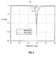
- Figure 3 illustrates at graphical representation 92 illustrating plots 94 and 96 that are representative of simulated and measured return losses, respectively, plotted as a function of frequency.
- the antenna is resonant at the 2.4 GHz frequency band, and the plots are indicative thereof.
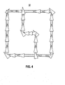
- Figure 4 again illustrates the antenna 32 of an exemplary embodiment of the present invention.
- the antenna headers represent the current in the antenna.
- Analysis of the current distribution indicates that the current distribution is in directions parallel to the polarization axes 72 and 74 shown in Figure 2 .
- Figures 5 and 6 illustrate, respectively, simulated and measured, two-dimensional, radiation patterns of the antenna 32 of an embodiment af the present invention at its 2.47 GHz resonant frequency. In each, representation, both zero and ninety degree-plane representations 102 and 104 are plotted.
- Figure 7 illustrates a graphical representation 106 illustrating simulated gain, as a function of frequency, exhibited by the antenna 32 of an embodiment of the present invention.
- the gain is centered at, or close to, the 2.47 GHz resonant frequency.
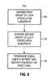
- Figure 8 illustrates a method flow diagram, shown generally at 112, representative of the method of operation of an embodiment of the present invention.
- the method is for transducing signal energy at a radio device.
- a first group of loop strips are disposed upon a substrate.
- the loop strips of the first group are configured to form a first loop having at least one strip extending in a first polarization direction and at least one strip extendingin a second polarization direction.
- a second group of loop strips are disposed upon the substrate.
- The, loop strips of the second group are configured to form a second loop having at least one strip extending in the first polarization direction and at least one strip extending in the second polarization direction.
- the loop strips are used to transduce signal energy, polarized in the polarization direction and in the second polarization directions, at the first and second groups, respectively, of the loop strips.
Landscapes
- Engineering & Computer Science (AREA)
- Computer Networks & Wireless Communication (AREA)
- Variable-Direction Aerials And Aerial Arrays (AREA)
- Waveguide Aerials (AREA)
Abstract
Description
- The present invention relates generally to an antenna for a portable radio device, such as a Bluetooth-capable or IEEE 802.11-capable device that operates at the IMS (Industry, Medical and Scientific) frequency band. More particularly, the present invention relates to a dual-polarized antenna, and an associated methodology, of compact construction, capable of positioning at, or within, a radio housing of the portable radio device.
- L-cornered antenna loops, formed of loop strips, are disposed upon a substrate. The loop strips extend in either of a first polarization direction or a second polarization direction, the second polarization direction orthogonal to the first polarization direction. The loop strips are of dimensions and are connected together to be resonant at the IMS, or other selected, frequency band at orthogonal polarization directions.
- Radio communication systems are used by many in modern society to communicate. Many varied communication services, both voice communication services and data communication services, are regularly effectuated by way of radio communication systems. And, as technological advancements permit, the types of communication services effectuable by way of radio communication systems shall likely increase.
- Cellular communication systems are exemplary of radio communication systems that have high levels of usage. Cellular Communication systems are typically constructed to provide wide-area coverage. And, their infrastructures have been installed over significant portions of the populated areas of the world. A user communicates by way of a radio communication system through use of a wireless device, a radio transceiver, sometimes referred to as a mobile station or user equipment (UE). Typically, access to a cellular communication system is provided pursuant to purchase of a subscription, either on a revolving, e.g., monthly basis, or an a pre-paid, time-usage basis. Cellular communication systems, operable pursuant to different operating standards, define radio air interfaces at different frequency bands, for instance, at the 800 MHz frequency band, at the 900 MHz frequency band, and at bands located between 1.7 GHz and 2.2 GHz.
- Other types of radio communication systems are also widely used, for instance, Bluetooth (tm)-based and IEEE 802.11-based systems, implemented, e.g., as, WLAN (Wireless Local Area Network) systems, also provide for voice and data communications, generally over smaller coverage areas than their cellular counterparts. WLANs are regularly operated as private networks, providing users who have access to such networks the capability to communicate therethrough through the use of Bluetooth-capable or 802.11-capable wireless devices. WLANs are sometimes configured to be connected to public networks, such as the Internet, and, in turn, to other communication networks, such as PSTNs (Public Switched Telephonic Networks) and PLMNs (Public Land Mobile Networks). Interworking entities also are sometimes provided to provide more-direct connection between the small-area networks and a PLMN. Various of the aforementioned, systems are implemented at the 2.4 GHZ frequency band.
- Radio communication systems are generally bandwidth-constrained. That is to say, bandwidth allocations for their operation are limited. And, such limited allocation of bandwidth, imposes limits upon the communication capacity of the communication system. Significant efforts have been made, and attention directed towards manners by which, to efficiently utilise the limited bandwidth allocated in bandwidth-constrained systems. Dual-polarization communication techniques are sometimes utilized. In a dual-polarization technique, data communicated at the same frequency is communicated in separate, polarized planes. Close to a doubling of the communication capacity is possible through the use of dual-polarization techniques. To transduce signal energy pursuant to a dual-polarization scheme, the wireless device is required to utilize a dual-polarized antenna, operable in the separate polarization planes. Use of dual-polarization techniques also are advantageous for the reason that the effects of multi-path, transmission and other interference are generally reduced, thereby improving quality of signal transmission and reception.
- A dual-polarized antenna is realizable, for instance, by feeding a square patch antenna at two orthogonal edges thereof by way of an edge feed or a probe feed. Generally, existing dual-polarized patch antennas are used in conjunction with two feeding-network circuits. Such existing antennas suffer from various limitations. For instance, separation distances between the feed connections are required to be great enough to prevent occurrence of coupling between the respective feeding lines. Excessive amounts of coupling results in high cross polarization levels.
- As wireless devices are of increasingly small dimensions, packaged in housings of increasingly-smaller dimensions, problems associated with the cross-polarization levels are likely to become more significant. An improved, dual-polarized antenna, constructed in a manner to reduce such deleterious problems is needed.
- It is in light of this background information related to antennas for radio devices that the significant improvements of the present invention have evolved.
-
Figure 1 illustrates a functional block diagram of a radio communication system in which an embodiment of the present invention is operable. -
Figure 2 illustrates a plan view of a dual-polarized, multiple-strip loop antenna of an embodiment of the present invention. -
Figure 3 illustrates a graphical representation showing simulated and measured return losses plotted as a function of frequency of an antenna forming part of a wireless device of an exemplary embodiment of the present invention. -
Figure 4 illustrates a representation of an exemplary, simulated current distribution of an antenna of an embodiment of the present invention. -
Figure 5 illustrates a graphical representation of simulated radiation patterns of antenna of an embodiment of the present invention at 2.47GHz. -
Figure 6 illustrates, a graphical representation, similar to that shown inFigure 5 , but of measured radiation patterns exhibited by an antenna of an embodiment of the present invention at 2.47 GHz. -
Figure 7 illustrates a graphical representation showing simulated gain as a function of an antenna of an embodiment of the present invention. -
Figure 8 illustrates a method flow diagram representative of the method of operation of an embodiment of the present invention. - The present invention, accordingly, advantageously provides antenna apparatus, and an associated method, for a portable radio device, such as a Bluetooth-compatible or 802.11-compatible device that operates at the IMS (Industy, Medical and Scientific) frequency band.
- Through operation of an embodiment of the present invention, a dual-polarized antenna of compact construction is provided. The antenna is capable of positioning at, or within, a radio housing of the portable radio device.
- In one aspect of the present invention, the antenna is formed of loop strips etched upon a substrate, configured in a manner to be resonant at a selected frequency band, such as a frequency band located at 2.47 GHz. The substrate is of dimensions permitting its positioning, together with the loop strips etched thereon, within the housing of a portable radio device, such as a wireless device operable in a Bluetooth-compatible or 802.11 -compatible system. Signal energy polarized in orthogonal, or other, directions. Transduced signal energy generated at the wireless device is transduced into electromagnetic form by the antenna and propagated therefrom in the polarized directions. And, electromagnetic energy communicated to the wireless device in the polarized directions is transduced into electrical form for subsequent operations thereon by circuitry of the radio device.
- In another aspect of the present invention, a first group of the loop strips etched onto the substrate is configured to form an L-cornered antenna loop. The L-cornered loop is formed by configuring adjacent loop strips such that ends of the adjacent loop strips intersect at substantially perpendicular angles. The loop strips of the first group, so-configured, are all, therefore positioned variously to extend in a first polarization direction or a second polarization direction, the second polarization direction orthogonal to the first polarization direction.
- In another aspect of the present invention, a second group of loop strips etched onto the substrate define a second L-cornered loop. Adjacent ones of the loop strips are configured to be connected at their ends at intersecting, substantially-perpendicular angles, thereby to be rectangular-cornered. And, each loop strip, so-configured, extends variously in a first polarization direction or a second polarization direction, orthogonal to a first polarization direction. Signal energy is transduced by the second loop, also in the two polarization directions.
- In another aspect of the present invention, the first group and second group of the loop strips include a shared set of loop strips, i.e., loop strips that are common to both the first group and the second group. The shared set of loop strips form part of the first antenna loop and part of the second antenna loop. At least one of the loop strips of the shared set extends in the first polarization direction, and at least one of the loop strips of the shared set extends in the second polarization direction. And, more specifically, the shared set includes at least two loop strips that extend in the first polarization direction and at least one loop strip that extends in the second polarization direction. The loop strips that extend in the first polarization direction are connected together by way of a loop strip that extends in the second polarization direction.
- In another aspect of the present invention, a single feed connection is provided for both of the polarization directions. The single feed connection is formed, or otherwise defined, at a loop strip of the shared set. The feed connection is positioned to Permit symmetrical excitation of the two antenna loops. Through the use of the single feed connection, problems associated with cross polarization are reduced. A high-gain, high-efficiency, and compact, dual-polarized antenna is thereby provided.
- In these and other aspects, therefore, antenna apparatus, and an associated methodology is provided for a radio device. A substrate is provided. And a first group of loop strips is disposed upon the substrate. The loop strips of the first group are configured to form a first loop having at least one loop strip extending in a first polarization direction and at least one loop strip extending in a second polarization direction. A second group of loop strips is disposed upon the substrate. The loop strips of the second group are configured to form a second loop having at least one strip that extends in the first polarization direction and at least one strip extending in the second polarization direction. The first and second groups of loop strips each have loop strips that extend in the first and second polarization directions, respectively, and exhibit dual-polarization operation.
- Turning first, therefore, to
Figure 1 , a radio communication system, shown generally at 10, provides for communications with amobile station 12. The mobile station, in the exemplary implementation, operates pursuant to a Bluetooth standard or IEEE 802.11 (b) or (g) standard, operable to send and to receive signals at the 2.4 GHz band. More generally, themobile station 12 is representative of any of various wireless devices, and the radio communication, system is representative of any various radio communication systems operable in conformity with any of various communication standards or permitting of operation at unregulated frequency bands. Accordingly, while the following description shall describe exemplary operation of a Bluetooth or IEEE 802.11-compliant system, operable at the 2.4 GHz frequency band, it should be understood that the following description is merely exemplary and that the description of operation of me radio communication system operable in conformity in another manner is analogous. - The radio communication system includes a network part, here represented by a
network station 14. The network station comprises, for instance, an access point of a WLAN or an analogous entity that transceives signals with wireless devices, such as themobile station 12. The network station, which here forms an access point, is part of a local network structure (WLAN) 16 that, in turn, is coupled to an external network, here a public packet data network (PDN) 18, such as the Internet. - The operating standard pursuant to which the mobile and, network stations are operable is permitting of, and here provides for, dual-polarized communications at the operational frequençy band of the communication system, here an ISM band that extends between 2.40 and 2.485 GHz.
- The
mobile station 12 includes transceiver circuitry, here represented-by a receive (RX)part 26 and a transmit: (TX)part 28. The receive and transmit parts are coupled, such as by way of an antenna coupler or other entity that provides isolation between the transceiver parts to anantenna 32 of an embodiment of the present invention. The transceiver circuitry is capable of dual-polarization operation. That is to say, the transmit and receive parts are capable of generating signals, for transmission in both of the polarization directions and also to operate upon signals communicated to the mobile station in both of the polarization directions. - Correspondingly, the
antenna 32 forms a dual-polarized antenna, capable of transducing signal energy of both of the polarization directions. That is to say, signal energy is, detected by the antenna in both of the dual-polarization directions. And, signal energy generated at the mobile station is transduced into electromagnetic forum and radiated in both of the dual polarization directions. In the exemplary implementation, theantenna 32 is disposed upon a generally planar substrate, of dimensions permitting its positioning within a housing of the mobile station. -
Figure 2 illustrates in greater detail theantenna 32 of an embodiment of the present invention and that forms part of themobile station 12, shown inFigure 1 . The antenna is formed of a plurality of loop strips 42 disposed upon a substrate The loops strips are etched, painted, or otherwise formed upon me substrate. The loop strips are configured such that adjacent ones of the loop strips abut against one another in electrical connection therebetween. The loop strips are of lengths and widths and are connected together so as to be resonant at a desire frequency band, here the, 2A GHz frequency band. - The loop strips are arranged into a rectangular loop structure comprised of a
first group 46 of loop strips and asecond group 48 of loop strips. The adjacent loop strips intersect at their ends in substantially perpendicular intersecting angles. Thegroups - The loop strips, of the
loops groups - The shared set, in the exemplary implementation, and as shown, includes three loop strips, connected end-to-end,including two L-cornered portions.
-
Figure 2 illustratesreferences axes axis 74 defines a first polarization direction, and theaxis 72 defines a second polarization direction. Loop strips that extend betweenreference points reference points reference points reference points reference points reference points reference points reference points reference points - The
antenna 32 includes a singlefed connection 82 providing a feed connection point, connectable to the tranceiver circuitry (shown inFigure 1 ) of the mobile station (shown inFigure 1 ). The single feed connection provides a feed that, positioned as-illustrated at a mid-point of the loop strip 66-68, provides; for symmetrical excitation of the loops formed of thegroups - The geometrical configuration of the exemplary implementation of the
antenna 32 shown inFigure 2 provides for three in-phase parallel strips in each of thepolarization directions - The two
groups 46 and48 of loop strips are etched on a printed board, or other substrate. The loop stripsare regarded as a combination of two electrically-connected multiple L-shaped, loop strips that have a common set of shared strips. In a further implementation, the antenna further includes ametal reflector 84 disposed in the strip-loop aperture plane, here disposed beneath a bottom surface of thesubstrate 44. - Orthogonal, dual-polarization radiation is realized by arranging the loop strips to extend in directions parallel to one of the
axes feed connection 82, located at the center of the loop strip 66-68, provides for symmetrical excitation, thereby to reduce cross-polarization levels of the dual-polarizationcomponents. The loop strips extending in each of the polarization directions are arranged into an in-phase, three-element array that provides high gain levels. The current, i.e., charge flow, direction during operation of the antenna reverses at half-wavelength intervals due to standing wave distributions along the strips. Additionally, each side of the outer-perimetal loop is divided equivalently into three sections, thereby to produce an in-phase current distribution on all of the strip sections if the length of the parimetal loop is appropriately chosen. -
Figure 3 illustrates atgraphical representation 92 illustratingplots -
Figure 4 again illustrates theantenna 32 of an exemplary embodiment of the present invention. Here, a simulated current distribution exhibited by the antenna at its resonant frequency of 2.47 GHz. The antenna headers represent the current in the antenna. Analysis of the current distribution indicates that the current distribution is in directions parallel to the polarization axes 72 and 74 shown inFigure 2 . -
Figures 5 and6 illustrate, respectively, simulated and measured, two-dimensional, radiation patterns of theantenna 32 of an embodiment af the present invention at its 2.47 GHz resonant frequency. In each, representation, both zero and ninety degree-plane representations -
Figure 7 illustrates agraphical representation 106 illustrating simulated gain, as a function of frequency, exhibited by theantenna 32 of an embodiment of the present invention. The gain is centered at, or close to, the 2.47 GHz resonant frequency. -
Figure 8 illustrates a method flow diagram, shown generally at 112, representative of the method of operation of an embodiment of the present invention. The method is for transducing signal energy at a radio device. - First, and as indicated by the
block 114, a first group of loop strips are disposed upon a substrate. The loop strips of the first group are configured to form a first loop having at least one strip extending in a first polarization direction and at least one strip extendingin a second polarization direction. And, as indicated by theMock 116, a second group of loop strips are disposed upon the substrate. The, loop strips of the second group are configured to form a second loop having at least one strip extending in the first polarization direction and at least one strip extending in the second polarization direction. - Once formed on the substrate, the loop strips are used to transduce signal energy, polarized in the polarization direction and in the second polarization directions, at the first and second groups, respectively, of the loop strips.
- Thereby, a dual-polarized antenna, of compact dimensions is provided. Through the use of loop strips disposed upon a substrate, configured in a, manner to permit use of a single feed connection to symmetrically excite the antenna, so-configured, obviates the problems associated with multiple feed connections used by conventional dual-polarized antennas are obviated.
Aspects and features of the present disclosure are set out in the following numbered clauses which contain the subject manor of the claims of the parent application as filed. - 1. Antenna apparatus for a radio device, said antenna apparatus comprising:
- a substrate;
- a first group of loop strips disposed upon said substrate, the loop strips of said first group configured to form a first loop having at least one strip extending in a first polarization direction and at least one strip extending in a second polarization direction; and
- a second group of loop strips disposed upon said substrate, the loop strips of said second group configured to form a second loop having at least one strip extending in the first polarization direction and at least one strip extending in a second polarization direction, said first group and said second group, each having strips extending in the first and second polarization directions, respectively, exhibiting no dual-polarization operation.
- 2. The antenna apparatus, of clause 1 wherein the first loop, into which the loop strips of said first group an configured, composes a first rectangular loop.
- 3. The antenna apparatus of clause 1 wherein adjacent ones of the strips of said first group intersect at substantially perpendicular angles relative, to one another.
- 4. The antenna apparatus of clause 1 wherein the second loop, into which the loop strips of said second group are configured, comprises a second rectangular loop.
- 5. The antenna, apparatus of
clause 4 wherein adjacent ones of the strips of said second group intersect at substantially perpendicular angles relative to one another. - 6. The antenna apparatus of clause I wherein said first group of loop strips and said second group of loop strips include a shared set of loop strips.
- 7. The antenna apparatus of
clause 6 wherein the shared set includes at least one loop strip extending in the first polarization direction and at least one loop strip extending in the second polarization direction. - 8. The antenna apparatus of clause 7 wherein the at least one loop strip of the shared set of loop strips that extends in the first polarization directions comprises a pair of loop strips that extend in the first polarization direction.
- 9. The antenna apparatus of
clause 8 wherein the loop strips of the pair of loop strips of the shared set are connected by the at least one loop strip of the shared set - that extends in the second polarization direction. - 10. The antenna apparatus of clause 9 further comprising a single feed connection formed at the at least one loop strip of the shared set that extends in the second polarization direction.
- 11. The antenna apparatus of clause 1 further comprising a single feed connection formed at a loop strip of at least one of said first group and said second group, said single feed connection configured to provide symmetrical excitation of loop strips of said first group and said second group.
- 12. The antenna apparatus of clause 1 wherein said first group of loop strips and said second groups of loop strips are configured to be resonant at a 2.4 GHz frequency band.
- 13. A dual-polarized antenna apparatus for a radio device housed at a radio housing, said antenna apparatus comprising:
- a substrate positionable within the radio housing;
- a first L-cometed antenna loop comprised of a, first plurality of loop stripes etched upon said substrate, each loop strip of the first plurality extending in one of a first polarization direction and a second polarization direction.
- a second L-cornered antenna loop comprised of a second plurality of loop strips etched upon said substrate, each loop strip of the second plurality extending in one of the first: polarization direction and the second polarization direction, said first L-cornered antenna loop and said second L-cornered antenna loop resonant within a selected frequency band to transduce signal energy polarized in the first polarization direction and in the second polarization direction.
- 14. The dual-polarized antenna apparatus of clause 13 wherein the selected frequecy band at which said first and second L-cornered antenna loops, respectively, are configured to be resonant comprises, an ISM, Industrial Scientific and Medical, frequency band.
- 15. A method for transducing signal energy at a radio device, said method comprising the operations of:
- disposing a first group of loop strips upon a substrate, the loop strips of the first group configured to form a first loop having at least one strip extending in a first polarization direction and at least one strip extending in a second polarization direction;
- disposing a second group of loop strips upon the substrate, the loop strips of the second group configured to form a second loop having at least one strip extending in the first polarization direction and at least one strip extending in the second polarization direction; and
- transducing signal energy, polarized in the first polarization direction and in the second polarization direction, at the first and second groups, respectively, of the loop strips disposed upon the substrate during said operations of disposing.
- 16. The method of clause 15 further comprising the operation of connecting to radio device to the first and second groups of the loop strips disposed during said operations of disposing.
- 17.The method of
clause 16 further comprising the operation of symmetrically exciting the first and second groups of the loop strips with signal energy. - 18. The method of clause 15 wherein the loop strips of the first and second groups, respectively, disposed during said operations, of disposing include a shared set of loop strips, shared by both the first group and the second group.
- 19. The method of
clause 18 wherein the shared set of the loop strips includes at least one loop strip extending in the first polarization direction and at least one loop strip extending in the second polarization direction. - 20. The method of clause: 15 wherein the loop strips disposed during said operations of disposing define an in-phase, three-element array in each of the first and second polarization directions.
Claims (14)
- Antenna apparatus for a radio device, said antenna apparatus: comprising:a substrate;a first group of loop strips disposed upon said substrate, the loop strips of said first group configured to form a parallelogram, the loop strips of said first group having at least one strip extending in a first polarization direction and at least one strip extending in a second polarization direction; anda second groups of loop strips disposed upon said substrate, the loop strips of said second group configured to divide the parallelogram into two substantially equal parts, with the loop strips of said second group extending from a first side of the parallelogram to a second side of the parallelogram, the loop strips of said second group having at least one strip extending in the first polarization direction and at least one strip extending: in a second polarization direction, said first group and said second group, each having strips extending in the first and second polarization directions, respectively, exhibiting dual-polarization operation.
- The antenna apparatus of claim 1 wherein adjacent ones of the strips of said first group intersect at substantially perpendicular angles relative to one another.
- The antenna apparatus of claim 1 wherein adjacent ones of the strips of said second group intersect at substantially perpendicular angles relative to one another.
- The antenna apparatus of claim 1 wherein two loop strips of said first group of loop strips and one loop atrip of said second group of loop strips extend in the first polarization direction.
- The antenna apparatus of claim 4 wherein two loop strips of said first group of loop strips and two loop strips of said second group of loop strips extend in the second polarization direction.
- The antenna apparatus of claim 1 wherein two loop strips of said first group of loop strips and two loop strips of said second group of loop strips extend in the second polarization direction.
- The antenna apparatus of claim 1 wherein once loop strip of said second group of loop strips extends in the first polarization direction and two loop strips of said second group of loop strips extend in the second polarization direction.
- The antennas apparatus of claim 7 further comprising a single feed connection formed at the one loop strip said second group of loop strips that extends in the first polarization direction.
- The antenna apparatus of claim 1 further comprising a single feed connection formed at a loop strip of at least one of said first group and said second group, said single feed connection configured to provide symmetrical excitation of loop strips of said first group and said second group
- A method for transducing signal energy at a radio device, said method comprising the operations of:disposing a first group of loop strips upon a substrate, the loop strips of the first group configured to form a parallelogram, the loop strips of the first loop having at least one strip extending in a first polarization directions and at least one strip extending in a second polarization direction;disposing a second, group of loop strips upon the substrate, the loop strips of the second group configured to divide the parallelogram into two substantially equal parts, with the loop strips of the second group extending from a first side of the parallelogram to a second side of the parallelogram, the loop strips of said second group having at least one strip extending in the first polarization direction and at least one strip extending in the second polarization direction; andtransducing signal energy, polarized in the first polarization direction and in the second polarization direction at the first and second groups, respectively, of the loop strips disposed upon the substrate during said operations of disposing.
- The method of claim 10 further comprising the operation of connecting to radio device to the first and second groups of the loop strips disposed during said operations of disposing.
- The method of claim 11 further comprising the operation of symmetrically exciting the first and second groups of the loop strips with signal energy.
- The method of claim 12 wherein the the loop strips of the second group includes at least one loop strip extending in the first polarization direction and at least one loop strip extending in the second polarization direction.
- The method of claim 10 wherein the loop strips disposed during said operations of disposing define an in-phase, three-element array in each of the first and second polarization directions.
Priority Applications (1)
| Application Number | Priority Date | Filing Date | Title |
|---|---|---|---|
| EP10194345.4A EP2299537B1 (en) | 2007-04-16 | 2007-04-16 | Portable radio device with a dual-polarized multi-strip loop antenna and associated method |
Applications Claiming Priority (2)
| Application Number | Priority Date | Filing Date | Title |
|---|---|---|---|
| EP10194345.4A EP2299537B1 (en) | 2007-04-16 | 2007-04-16 | Portable radio device with a dual-polarized multi-strip loop antenna and associated method |
| EP07106265.7A EP1983606B1 (en) | 2007-04-16 | 2007-04-16 | Dual-polarized, multiple strip-loop antenna and associated methodology, for radio device |
Related Parent Applications (3)
| Application Number | Title | Priority Date | Filing Date |
|---|---|---|---|
| EP07106265.7A Division EP1983606B1 (en) | 2007-04-16 | 2007-04-16 | Dual-polarized, multiple strip-loop antenna and associated methodology, for radio device |
| EP07106265.7A Division-Into EP1983606B1 (en) | 2007-04-16 | 2007-04-16 | Dual-polarized, multiple strip-loop antenna and associated methodology, for radio device |
| EP07106265.7 Division | 2007-04-16 |
Publications (3)
| Publication Number | Publication Date |
|---|---|
| EP2299537A2 true EP2299537A2 (en) | 2011-03-23 |
| EP2299537A3 EP2299537A3 (en) | 2011-06-29 |
| EP2299537B1 EP2299537B1 (en) | 2020-01-01 |
Family
ID=38038662
Family Applications (2)
| Application Number | Title | Priority Date | Filing Date |
|---|---|---|---|
| EP10194345.4A Active EP2299537B1 (en) | 2007-04-16 | 2007-04-16 | Portable radio device with a dual-polarized multi-strip loop antenna and associated method |
| EP07106265.7A Active EP1983606B1 (en) | 2007-04-16 | 2007-04-16 | Dual-polarized, multiple strip-loop antenna and associated methodology, for radio device |
Family Applications After (1)
| Application Number | Title | Priority Date | Filing Date |
|---|---|---|---|
| EP07106265.7A Active EP1983606B1 (en) | 2007-04-16 | 2007-04-16 | Dual-polarized, multiple strip-loop antenna and associated methodology, for radio device |
Country Status (7)
| Country | Link |
|---|---|
| EP (2) | EP2299537B1 (en) |
| KR (1) | KR101087418B1 (en) |
| CN (1) | CN101388493B (en) |
| BR (1) | BRPI0803648B1 (en) |
| CA (1) | CA2629178C (en) |
| MX (1) | MX2008004911A (en) |
| TW (1) | TWI362785B (en) |
Cited By (1)
| Publication number | Priority date | Publication date | Assignee | Title |
|---|---|---|---|---|
| US10389034B2 (en) | 2015-01-16 | 2019-08-20 | Kabushiki Kaisha Toshiba | Antenna |
Families Citing this family (1)
| Publication number | Priority date | Publication date | Assignee | Title |
|---|---|---|---|---|
| US8164532B1 (en) * | 2011-01-18 | 2012-04-24 | Dockon Ag | Circular polarized compound loop antenna |
Family Cites Families (4)
| Publication number | Priority date | Publication date | Assignee | Title |
|---|---|---|---|---|
| ATE360268T1 (en) * | 2002-12-23 | 2007-05-15 | Huber+Suhner Ag | BROADBAND ANTENNA WITH A 3-DIMENSIONAL CASTING |
| US7307591B2 (en) * | 2004-07-20 | 2007-12-11 | Nokia Corporation | Multi-band antenna |
| JP4519034B2 (en) | 2004-12-28 | 2010-08-04 | Dxアンテナ株式会社 | antenna |
| CN2879454Y (en) * | 2005-09-09 | 2007-03-14 | 摩比天线技术(深圳)有限公司 | Double polarization antenna |
-
2007
- 2007-04-16 EP EP10194345.4A patent/EP2299537B1/en active Active
- 2007-04-16 EP EP07106265.7A patent/EP1983606B1/en active Active
-
2008
- 2008-04-14 CN CN200810109282.3A patent/CN101388493B/en active Active
- 2008-04-14 MX MX2008004911A patent/MX2008004911A/en active IP Right Grant
- 2008-04-15 BR BRPI0803648-9A patent/BRPI0803648B1/en active IP Right Grant
- 2008-04-15 KR KR1020080034840A patent/KR101087418B1/en active Active
- 2008-04-15 TW TW097113691A patent/TWI362785B/en active
- 2008-04-15 CA CA2629178A patent/CA2629178C/en active Active
Non-Patent Citations (1)
| Title |
|---|
| None |
Cited By (1)
| Publication number | Priority date | Publication date | Assignee | Title |
|---|---|---|---|---|
| US10389034B2 (en) | 2015-01-16 | 2019-08-20 | Kabushiki Kaisha Toshiba | Antenna |
Also Published As
| Publication number | Publication date |
|---|---|
| TW200901565A (en) | 2009-01-01 |
| EP2299537A3 (en) | 2011-06-29 |
| EP1983606A1 (en) | 2008-10-22 |
| CA2629178C (en) | 2013-03-19 |
| BRPI0803648B1 (en) | 2021-09-08 |
| MX2008004911A (en) | 2009-03-02 |
| EP2299537B1 (en) | 2020-01-01 |
| BRPI0803648A2 (en) | 2009-04-22 |
| CN101388493A (en) | 2009-03-18 |
| KR101087418B1 (en) | 2011-11-25 |
| TWI362785B (en) | 2012-04-21 |
| KR20080093384A (en) | 2008-10-21 |
| EP1983606B1 (en) | 2016-03-16 |
| CN101388493B (en) | 2014-04-16 |
| CA2629178A1 (en) | 2008-10-16 |
Similar Documents
| Publication | Publication Date | Title |
|---|---|---|
| US7508346B2 (en) | Dual-polarized, microstrip patch antenna array, and associated methodology, for radio device | |
| EP3857642B1 (en) | MULTI-LAYER PATCH ANTENNA | |
| US7511670B2 (en) | Dual-polarized, multiple strip-loop antenna, and associated methodology, for radio device | |
| EP2660933B1 (en) | Array antenna of mobile terminal and implementing method thereof | |
| US7057558B2 (en) | Antenna device | |
| US12381334B2 (en) | Antenna device, array of antenna devices, and base station with antenna device | |
| CN110783706B (en) | Same-frequency integrated antenna and customer premises equipment | |
| US20110279344A1 (en) | Radio frequency patch antennas for wireless communications | |
| EP4732374A1 (en) | Broadband patch antenna | |
| CA2629183C (en) | Dual-polarized, microstrip patch antenna array, and associated methodology, for radio device | |
| EP1983606B1 (en) | Dual-polarized, multiple strip-loop antenna and associated methodology, for radio device | |
| EP4216241A1 (en) | Transformer for low loss, and device comprising same | |
| WO2025072367A1 (en) | Antenna systems | |
| EP4254662A1 (en) | Antenna structure and electronic device comprising same | |
| Adesoye et al. | Mutual coupling in a collocated dipole antenna setup: A comprehensive review | |
| CN114552218A (en) | MIMO antenna and communication device | |
| CN215418597U (en) | Slot antenna | |
| AU2024348943A1 (en) | Antenna systems | |
| WO2025226867A1 (en) | Antenna systems | |
| CN121263924A (en) | Multi-frequency range antenna | |
| Sun et al. | The omni-directional dipole antenna structure and design |
Legal Events
| Date | Code | Title | Description |
|---|---|---|---|
| PUAI | Public reference made under article 153(3) epc to a published international application that has entered the european phase |
Free format text: ORIGINAL CODE: 0009012 |
|
| 17P | Request for examination filed |
Effective date: 20101209 |
|
| AC | Divisional application: reference to earlier application |
Ref document number: 1983606 Country of ref document: EP Kind code of ref document: P |
|
| AK | Designated contracting states |
Kind code of ref document: A2 Designated state(s): AT BE BG CH CY CZ DE DK EE ES FI FR GB GR HU IE IS IT LI LT LU LV MC MT NL PL PT RO SE SI SK TR |
|
| AX | Request for extension of the european patent |
Extension state: AL BA HR MK RS |
|
| PUAL | Search report despatched |
Free format text: ORIGINAL CODE: 0009013 |
|
| AK | Designated contracting states |
Kind code of ref document: A3 Designated state(s): AT BE BG CH CY CZ DE DK EE ES FI FR GB GR HU IE IS IT LI LT LU LV MC MT NL PL PT RO SE SI SK TR |
|
| AX | Request for extension of the european patent |
Extension state: AL BA HR MK RS |
|
| 17Q | First examination report despatched |
Effective date: 20120308 |
|
| RAP1 | Party data changed (applicant data changed or rights of an application transferred) |
Owner name: BLACKBERRY LIMITED |
|
| RAP1 | Party data changed (applicant data changed or rights of an application transferred) |
Owner name: BLACKBERRY LIMITED |
|
| STAA | Information on the status of an ep patent application or granted ep patent |
Free format text: STATUS: EXAMINATION IS IN PROGRESS |
|
| GRAP | Despatch of communication of intention to grant a patent |
Free format text: ORIGINAL CODE: EPIDOSNIGR1 |
|
| STAA | Information on the status of an ep patent application or granted ep patent |
Free format text: STATUS: GRANT OF PATENT IS INTENDED |
|
| INTG | Intention to grant announced |
Effective date: 20190724 |
|
| GRAS | Grant fee paid |
Free format text: ORIGINAL CODE: EPIDOSNIGR3 |
|
| GRAA | (expected) grant |
Free format text: ORIGINAL CODE: 0009210 |
|
| STAA | Information on the status of an ep patent application or granted ep patent |
Free format text: STATUS: THE PATENT HAS BEEN GRANTED |
|
| AC | Divisional application: reference to earlier application |
Ref document number: 1983606 Country of ref document: EP Kind code of ref document: P |
|
| AK | Designated contracting states |
Kind code of ref document: B1 Designated state(s): AT BE BG CH CY CZ DE DK EE ES FI FR GB GR HU IE IS IT LI LT LU LV MC MT NL PL PT RO SE SI SK TR |
|
| REG | Reference to a national code |
Ref country code: GB Ref legal event code: FG4D |
|
| REG | Reference to a national code |
Ref country code: AT Ref legal event code: REF Ref document number: 1220951 Country of ref document: AT Kind code of ref document: T Effective date: 20200115 Ref country code: CH Ref legal event code: EP |
|
| REG | Reference to a national code |
Ref country code: IE Ref legal event code: FG4D |
|
| REG | Reference to a national code |
Ref country code: DE Ref legal event code: R096 Ref document number: 602007059705 Country of ref document: DE |
|
| REG | Reference to a national code |
Ref country code: NL Ref legal event code: MP Effective date: 20200101 |
|
| REG | Reference to a national code |
Ref country code: LT Ref legal event code: MG4D |
|
| PG25 | Lapsed in a contracting state [announced via postgrant information from national office to epo] |
Ref country code: FI Free format text: LAPSE BECAUSE OF FAILURE TO SUBMIT A TRANSLATION OF THE DESCRIPTION OR TO PAY THE FEE WITHIN THE PRESCRIBED TIME-LIMIT Effective date: 20200101 Ref country code: LT Free format text: LAPSE BECAUSE OF FAILURE TO SUBMIT A TRANSLATION OF THE DESCRIPTION OR TO PAY THE FEE WITHIN THE PRESCRIBED TIME-LIMIT Effective date: 20200101 Ref country code: CZ Free format text: LAPSE BECAUSE OF FAILURE TO SUBMIT A TRANSLATION OF THE DESCRIPTION OR TO PAY THE FEE WITHIN THE PRESCRIBED TIME-LIMIT Effective date: 20200101 Ref country code: NL Free format text: LAPSE BECAUSE OF FAILURE TO SUBMIT A TRANSLATION OF THE DESCRIPTION OR TO PAY THE FEE WITHIN THE PRESCRIBED TIME-LIMIT Effective date: 20200101 Ref country code: PT Free format text: LAPSE BECAUSE OF FAILURE TO SUBMIT A TRANSLATION OF THE DESCRIPTION OR TO PAY THE FEE WITHIN THE PRESCRIBED TIME-LIMIT Effective date: 20200527 |
|
| PG25 | Lapsed in a contracting state [announced via postgrant information from national office to epo] |
Ref country code: SE Free format text: LAPSE BECAUSE OF FAILURE TO SUBMIT A TRANSLATION OF THE DESCRIPTION OR TO PAY THE FEE WITHIN THE PRESCRIBED TIME-LIMIT Effective date: 20200101 Ref country code: LV Free format text: LAPSE BECAUSE OF FAILURE TO SUBMIT A TRANSLATION OF THE DESCRIPTION OR TO PAY THE FEE WITHIN THE PRESCRIBED TIME-LIMIT Effective date: 20200101 Ref country code: GR Free format text: LAPSE BECAUSE OF FAILURE TO SUBMIT A TRANSLATION OF THE DESCRIPTION OR TO PAY THE FEE WITHIN THE PRESCRIBED TIME-LIMIT Effective date: 20200402 Ref country code: IS Free format text: LAPSE BECAUSE OF FAILURE TO SUBMIT A TRANSLATION OF THE DESCRIPTION OR TO PAY THE FEE WITHIN THE PRESCRIBED TIME-LIMIT Effective date: 20200501 Ref country code: BG Free format text: LAPSE BECAUSE OF FAILURE TO SUBMIT A TRANSLATION OF THE DESCRIPTION OR TO PAY THE FEE WITHIN THE PRESCRIBED TIME-LIMIT Effective date: 20200401 |
|
| REG | Reference to a national code |
Ref country code: DE Ref legal event code: R097 Ref document number: 602007059705 Country of ref document: DE |
|
| PG25 | Lapsed in a contracting state [announced via postgrant information from national office to epo] |
Ref country code: ES Free format text: LAPSE BECAUSE OF FAILURE TO SUBMIT A TRANSLATION OF THE DESCRIPTION OR TO PAY THE FEE WITHIN THE PRESCRIBED TIME-LIMIT Effective date: 20200101 Ref country code: SK Free format text: LAPSE BECAUSE OF FAILURE TO SUBMIT A TRANSLATION OF THE DESCRIPTION OR TO PAY THE FEE WITHIN THE PRESCRIBED TIME-LIMIT Effective date: 20200101 Ref country code: RO Free format text: LAPSE BECAUSE OF FAILURE TO SUBMIT A TRANSLATION OF THE DESCRIPTION OR TO PAY THE FEE WITHIN THE PRESCRIBED TIME-LIMIT Effective date: 20200101 Ref country code: DK Free format text: LAPSE BECAUSE OF FAILURE TO SUBMIT A TRANSLATION OF THE DESCRIPTION OR TO PAY THE FEE WITHIN THE PRESCRIBED TIME-LIMIT Effective date: 20200101 Ref country code: EE Free format text: LAPSE BECAUSE OF FAILURE TO SUBMIT A TRANSLATION OF THE DESCRIPTION OR TO PAY THE FEE WITHIN THE PRESCRIBED TIME-LIMIT Effective date: 20200101 |
|
| PLBE | No opposition filed within time limit |
Free format text: ORIGINAL CODE: 0009261 |
|
| STAA | Information on the status of an ep patent application or granted ep patent |
Free format text: STATUS: NO OPPOSITION FILED WITHIN TIME LIMIT |
|
| REG | Reference to a national code |
Ref country code: AT Ref legal event code: MK05 Ref document number: 1220951 Country of ref document: AT Kind code of ref document: T Effective date: 20200101 |
|
| PG25 | Lapsed in a contracting state [announced via postgrant information from national office to epo] |
Ref country code: MC Free format text: LAPSE BECAUSE OF FAILURE TO SUBMIT A TRANSLATION OF THE DESCRIPTION OR TO PAY THE FEE WITHIN THE PRESCRIBED TIME-LIMIT Effective date: 20200101 |
|
| REG | Reference to a national code |
Ref country code: CH Ref legal event code: PL |
|
| 26N | No opposition filed |
Effective date: 20201002 |
|
| PG25 | Lapsed in a contracting state [announced via postgrant information from national office to epo] |
Ref country code: LI Free format text: LAPSE BECAUSE OF NON-PAYMENT OF DUE FEES Effective date: 20200430 Ref country code: CH Free format text: LAPSE BECAUSE OF NON-PAYMENT OF DUE FEES Effective date: 20200430 Ref country code: AT Free format text: LAPSE BECAUSE OF FAILURE TO SUBMIT A TRANSLATION OF THE DESCRIPTION OR TO PAY THE FEE WITHIN THE PRESCRIBED TIME-LIMIT Effective date: 20200101 Ref country code: IT Free format text: LAPSE BECAUSE OF FAILURE TO SUBMIT A TRANSLATION OF THE DESCRIPTION OR TO PAY THE FEE WITHIN THE PRESCRIBED TIME-LIMIT Effective date: 20200101 Ref country code: LU Free format text: LAPSE BECAUSE OF NON-PAYMENT OF DUE FEES Effective date: 20200416 |
|
| REG | Reference to a national code |
Ref country code: BE Ref legal event code: MM Effective date: 20200430 |
|
| PG25 | Lapsed in a contracting state [announced via postgrant information from national office to epo] |
Ref country code: PL Free format text: LAPSE BECAUSE OF FAILURE TO SUBMIT A TRANSLATION OF THE DESCRIPTION OR TO PAY THE FEE WITHIN THE PRESCRIBED TIME-LIMIT Effective date: 20200101 Ref country code: SI Free format text: LAPSE BECAUSE OF FAILURE TO SUBMIT A TRANSLATION OF THE DESCRIPTION OR TO PAY THE FEE WITHIN THE PRESCRIBED TIME-LIMIT Effective date: 20200101 Ref country code: BE Free format text: LAPSE BECAUSE OF NON-PAYMENT OF DUE FEES Effective date: 20200430 |
|
| PG25 | Lapsed in a contracting state [announced via postgrant information from national office to epo] |
Ref country code: IE Free format text: LAPSE BECAUSE OF NON-PAYMENT OF DUE FEES Effective date: 20200416 |
|
| PG25 | Lapsed in a contracting state [announced via postgrant information from national office to epo] |
Ref country code: TR Free format text: LAPSE BECAUSE OF FAILURE TO SUBMIT A TRANSLATION OF THE DESCRIPTION OR TO PAY THE FEE WITHIN THE PRESCRIBED TIME-LIMIT Effective date: 20200101 Ref country code: MT Free format text: LAPSE BECAUSE OF FAILURE TO SUBMIT A TRANSLATION OF THE DESCRIPTION OR TO PAY THE FEE WITHIN THE PRESCRIBED TIME-LIMIT Effective date: 20200101 Ref country code: CY Free format text: LAPSE BECAUSE OF FAILURE TO SUBMIT A TRANSLATION OF THE DESCRIPTION OR TO PAY THE FEE WITHIN THE PRESCRIBED TIME-LIMIT Effective date: 20200101 |
|
| REG | Reference to a national code |
Ref country code: DE Ref legal event code: R081 Ref document number: 602007059705 Country of ref document: DE Owner name: MALIKIE INNOVATIONS LTD., IE Free format text: FORMER OWNER: BLACKBERRY LIMITED, WATERLOO, ONTARIO, CA |
|
| PGFP | Annual fee paid to national office [announced via postgrant information from national office to epo] |
Ref country code: DE Payment date: 20250428 Year of fee payment: 19 |
|
| PGFP | Annual fee paid to national office [announced via postgrant information from national office to epo] |
Ref country code: GB Payment date: 20250422 Year of fee payment: 19 |
|
| PGFP | Annual fee paid to national office [announced via postgrant information from national office to epo] |
Ref country code: FR Payment date: 20250424 Year of fee payment: 19 |