EP2299470A2 - Methods and apparatus for filling an ion detector cell - Google Patents
Methods and apparatus for filling an ion detector cell Download PDFInfo
- Publication number
- EP2299470A2 EP2299470A2 EP10008853A EP10008853A EP2299470A2 EP 2299470 A2 EP2299470 A2 EP 2299470A2 EP 10008853 A EP10008853 A EP 10008853A EP 10008853 A EP10008853 A EP 10008853A EP 2299470 A2 EP2299470 A2 EP 2299470A2
- Authority
- EP
- European Patent Office
- Prior art keywords
- ion
- ions
- accumulator
- field
- axial
- Prior art date
- Legal status (The legal status is an assumption and is not a legal conclusion. Google has not performed a legal analysis and makes no representation as to the accuracy of the status listed.)
- Withdrawn
Links
- 238000000034 method Methods 0.000 title claims description 22
- 150000002500 ions Chemical class 0.000 claims abstract description 532
- 230000004323 axial length Effects 0.000 claims abstract description 47
- 238000001514 detection method Methods 0.000 claims description 5
- 230000004913 activation Effects 0.000 claims description 3
- 230000004044 response Effects 0.000 claims description 2
- 230000005684 electric field Effects 0.000 abstract description 39
- 238000000605 extraction Methods 0.000 abstract description 16
- 230000009977 dual effect Effects 0.000 abstract 2
- 210000004027 cell Anatomy 0.000 description 123
- 238000010586 diagram Methods 0.000 description 8
- 238000005086 pumping Methods 0.000 description 8
- 239000007789 gas Substances 0.000 description 7
- 230000005405 multipole Effects 0.000 description 6
- 230000000979 retarding effect Effects 0.000 description 6
- 238000004891 communication Methods 0.000 description 5
- 230000001133 acceleration Effects 0.000 description 4
- 230000008859 change Effects 0.000 description 4
- 238000005036 potential barrier Methods 0.000 description 4
- 230000032258 transport Effects 0.000 description 4
- 238000013016 damping Methods 0.000 description 3
- 238000013461 design Methods 0.000 description 3
- 230000005284 excitation Effects 0.000 description 3
- 230000033001 locomotion Effects 0.000 description 3
- 230000010355 oscillation Effects 0.000 description 3
- 238000012545 processing Methods 0.000 description 3
- 238000004458 analytical method Methods 0.000 description 2
- 230000008901 benefit Effects 0.000 description 2
- 238000006073 displacement reaction Methods 0.000 description 2
- 238000000132 electrospray ionisation Methods 0.000 description 2
- 230000014509 gene expression Effects 0.000 description 2
- 238000005040 ion trap Methods 0.000 description 2
- 238000000816 matrix-assisted laser desorption--ionisation Methods 0.000 description 2
- 238000009825 accumulation Methods 0.000 description 1
- 238000004364 calculation method Methods 0.000 description 1
- 210000002421 cell wall Anatomy 0.000 description 1
- 238000000451 chemical ionisation Methods 0.000 description 1
- 238000001816 cooling Methods 0.000 description 1
- 230000001419 dependent effect Effects 0.000 description 1
- 239000001307 helium Substances 0.000 description 1
- 229910052734 helium Inorganic materials 0.000 description 1
- SWQJXJOGLNCZEY-UHFFFAOYSA-N helium atom Chemical compound [He] SWQJXJOGLNCZEY-UHFFFAOYSA-N 0.000 description 1
- 230000010354 integration Effects 0.000 description 1
- 238000004949 mass spectrometry Methods 0.000 description 1
- 238000005259 measurement Methods 0.000 description 1
- 230000007246 mechanism Effects 0.000 description 1
- 239000002184 metal Substances 0.000 description 1
- 239000000203 mixture Substances 0.000 description 1
- 230000003287 optical effect Effects 0.000 description 1
- 239000002245 particle Substances 0.000 description 1
- 238000004150 penning trap Methods 0.000 description 1
- 230000000737 periodic effect Effects 0.000 description 1
- 230000009467 reduction Effects 0.000 description 1
- 238000001228 spectrum Methods 0.000 description 1
- 230000007480 spreading Effects 0.000 description 1
Images





Classifications
-
- H—ELECTRICITY
- H01—ELECTRIC ELEMENTS
- H01J—ELECTRIC DISCHARGE TUBES OR DISCHARGE LAMPS
- H01J49/00—Particle spectrometers or separator tubes
- H01J49/26—Mass spectrometers or separator tubes
- H01J49/34—Dynamic spectrometers
- H01J49/36—Radio frequency spectrometers, e.g. Bennett-type spectrometers, Redhead-type spectrometers
- H01J49/38—Omegatrons ; using ion cyclotron resonance
-
- H—ELECTRICITY
- H01—ELECTRIC ELEMENTS
- H01J—ELECTRIC DISCHARGE TUBES OR DISCHARGE LAMPS
- H01J49/00—Particle spectrometers or separator tubes
- H01J49/02—Details
- H01J49/04—Arrangements for introducing or extracting samples to be analysed, e.g. vacuum locks; Arrangements for external adjustment of electron- or ion-optical components
-
- H—ELECTRICITY
- H01—ELECTRIC ELEMENTS
- H01J—ELECTRIC DISCHARGE TUBES OR DISCHARGE LAMPS
- H01J49/00—Particle spectrometers or separator tubes
- H01J49/02—Details
- H01J49/06—Electron- or ion-optical arrangements
- H01J49/062—Ion guides
Definitions
- the present invention relates generally to filling a mass analyzer with ions, particularly in a mass spectrometry apparatus that includes linearly arranged ion-processing components.
- Ion trapping mass spectrometers utilizing magnetic confinement of the ions in the radial direction and DC voltages for axial confinement are known as Penning Traps or ion cyclotron resonance mass spectrometers (ICR-MS). Ions in the trapping cell oscillate at a frequency that depends on the magnetic field strength and the mass-to-charge (m/z) ratio of the ion. Ions trapped in the detector cell can absorb energy by resonance excitation from an applied electrical field alternating at the frequency of oscillation of the ions, and can be detected by measuring the electromotive force (EMF) induced in the trapping cell walls due to the oscillating charge of the ions by means known in the art.
- EMF electromotive force
- FTMS Fourier Transform Mass Spectrometers detect the masses of ions by exciting the ions in the detector cell by means of a voltage pulse containing a range of frequencies or a rapid frequency scan so as to increase the energy of all of the ions present in the cell when the excitation frequency matches the ion oscillation frequency.
- the detected voltage is a complex mixture of frequencies that corresponds to the natural oscillation of all of the ions that were excited.
- a Fourier Transform of the time domain voltage results in a frequency domain spectrum that directly represents the mass and relative abundances of the ions present.
- Ions are generally formed in an ion source located outside of the magnetic field and must be accumulated in an ion trapping device and then transported into the detector cell and in the magnetic field. Since there is no inherent means of increasing the number of charged particles that are detected when detecting ions by induced EMF, as is common in other types of mass spectrometers which utilize electron multipliers, it is necessary to have a large-volume detector cell that can hold several million ions. Typically at least 100 ions are required for a minimum detectable voltage.
- RF radio frequency
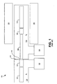
- FIG. 1 is a schematic view of a typical FTMS system 100 .
- ions travel in a general direction from left to right along an axis about which various ion-controlling devices are arranged.
- the FTMS system 100 generally includes an ion source (not shown) followed by, in succession along the axis, an ion accumulator 102 , a shutter assembly 104 , an ion guide 106 , an ion decelerator 108 , and an ion detector cell 110 .
- the FTMS system 100 also includes a housing 112 that encloses the ion accumulator 102 , the shutter assembly 104 , the ion guide 106 , the ion decelerator 108 and the ion detector cell 110 .
- the housing 112 defines a first vacuum region (or pumping stage) 114 and a second vacuum region (or pumping stage) 116 adjoined at a boundary 118 having a differential pumping aperture 120 located at the axis.
- the ion accumulator 102 and the shutter assembly 104 are positioned in the first pumping region 114 and the ion guide 106 , the ion decelerator 108 and the ion detector cell 110 are positioned in the second pumping region 116 .
- Suitable vacuum pumps 122 , 124 respectively maintain the first vacuum region 114 at a vacuum pressure P 1 and the second vacuum region 116 at a vacuum pressure P 2 lower than P 1 .
- the FTMS system 100 further includes a suitable magnet assembly 126 (e.g., including a superconducting magnet) that coaxially surrounds the ion detector cell 110 and may also surround the ion decelerator 108 and part of the ion guide 106.
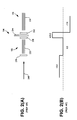
- FIG 2A is a side (lengthwise) view of the ion accumulator 102, shutter assembly 104 and ion guide 106 illustrated in figure 1 .
- the ion accumulator 102 and the ion guide 106 are typically structured as linear multipole electrode sets operating as ion traps.
- Each electrode set includes a set of parallel electrodes 232, 234 extending along the axis and circumferentially spaced from each other about the axis at radial distances in the transverse plane orthogonal to the axis, thereby circumscribing an axially elongated interior space in which ions may be confined and through which the ions travel.
- each electrode set includes six electrodes 232, 234 (hexapole arrangement) or eight electrodes 232, 234 (octopole arrangement).
- RF voltage sources (not shown) are connected to the electrodes 232, 234 in a known manner so as to apply a linear (two-dimensional) RF trapping field that confines the radial motions of the ions to a region along the axis.
- Respective lenses 236, 238 serve as the ion entrance to and ion exit from the ion accumulator 102.
- Another lens 242 serves as the ion entrance to the ion guide 106 and yet another lens (not shown) serves as the ion exit from the ion guide 106.
- the lenses 236, 238, 242 are typically plates with apertures located at the axis and are connected to DC voltage sources (not shown).
- the shutter assembly 104 is typically a series of lenses 244 configured to direct the ions through the differential pumping aperture 120 located between the two vacuum regions 114 and 116 ( figure 1 ).
- the shutter 104 also typically includes a movable, mechanical shutter element (not shown).
- the ion guide 106 may be provided as a series of axially spaced DC lenses that would likewise operate to confine the ions in the radial direction as the ions travel to the ion detector cell 110.
- ions 248 produced from a molecular sample in the ion source are transmitted in the ion accumulator 102.
- the ions are confined in the radial direction by the RF voltages applied to the electrodes 232 and in the axial direction by the DC voltages applied to the entrance lens 236 and the exit lens 238.
- Figure 2B illustrates typical DC voltages applied to the ion accumulator 102, shutter assembly 104 and ion guide 106 when trapping ions in the ion accumulator 102.
- a positive DC voltage (e.g., +5 V) is applied to the entrance lens 236, no DC voltage is applied to the electrodes 232 of the ion accumulator 102, a relatively higher DC voltage (e.g., +20 V) is applied to the exit lens 238, and a negative DC voltage (e.g., -7 V) is applied to the electrodes 234 of the ion guide 106.
- the low potential barrier at the entrance to the ion accumulator 102 allows the ions to enter the ion accumulator 102.
- the large potential barrier at the exit of the ion accumulator 102 prevents ions from passing completely through the ion accumulator 102 while the ions are being accumulated therein.
- the addition of a damping gas such as helium allows for the removal of excess kinetic energy by collisions so that the ions will not escape from the ion accumulator 102 by leaving through the aperture of the entrance lens 236.
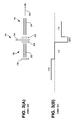
- Figures 3A and 3B illustrate the extraction of the ions from the ion accumulator 102.
- Figure 3A is a side (lengthwise) view of the ion accumulator 102, shutter assembly 104 and ion guide 106 similar to figure 2A
- figure 3B illustrates typical DC voltages applied to the ion accumulator 102, shutter assembly 104 and ion guide 106 when extracting the trapped ions from the ion accumulator 102.
- Ions are removed from the ion accumulator 102 by reducing the potential barrier at the exit lens 238, for example by changing the DC voltage on the exit lens 238 from +20 V to -20 V as shown in figure 3B .
- ions are accumulated so as to form space charge repulsion between the ions.
- the space charge repulsion along with the attractive potential from the exit lens 238 of the ion accumulator 102, causes ions to be removed from the ion accumulator 102 and directed through the shutter assembly 104 and into the ion guide 106.
- the shutter element of the shutter assembly 104 opens to allow ions to pass and closes after the ions have passed in order to reduce the gas load on the vacuum pump 124 in the second pumping region 116 ( figure 1 ), thereby allowing lower pressures to be maintained during the succeeding mass analysis time.
- the ions After traversing the differential pumping aperture 120 ( figure 1 ), the ions then travel through the ion guide 106. Ions 250 exiting the ion guide 106 are decelerated and transmitted into the magnetic field and into the ion detector cell 110.
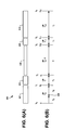
- Figure 4A is a side (lengthwise) view of the ion decelerator 108 and ion detector cell 110 illustrated in figure 1 , as well as part of the ion guide 106 preceding the ion detector cell 110.
- the ion detector cell 110 typically includes three axially spaced electrodes 454, 456, 458 (cylindrical rings or plates) with respective apertures aligned along the axis, and trapping plates 108, 462 positioned at the respective axial ends.
- the trapping plate 108 at the ion entrance is typically a lens with an aperture, and typically serves as the ion decelerator 108.
- the center electrode 456 is further segmented into radial quadrants (not shown) so as to have pairs of opposing sections that can be utilized as transmitting and receiving electrodes for ion detection and mass measurement.
- each electrode 454, 456, 458 can also have a DC potential applied thereto.
- Figure 4B illustrates typical DC voltages applied to the various electrodes of the ion guide 106, ion decelerator 108 and ion detector cell 110 when admitting ions in the ion detector cell 110, and also schematically illustrates the trajectory of the ions during this time.
- a negative DC voltage (e.g., -7 V) is applied to the electrodes 234 of the ion guide 106 as noted above, no DC voltage is applied to the ion decelerator 108, a positive DC voltage (e.g., +0.2 V) is applied to the first inner electrode 454, no DC voltage is applied to the center electrode 456, a positive DC voltage (e.g., +0.2 V) is applied to the second inner electrode 458, and a positive DC voltage (e.g., +15 V) is applied to the distal trapping plate 462.
- a positive DC voltage e.g., +0.2 V
- +15 V e.g., +15 V
- the voltage at the distal end of the ion detector cell 110 has a repulsive DC potential applied to prevent the in-coming ions from escaping the detector cell 110 at that end, as indicated schematically by the ion trajectory in figure 4B . Ions are confined in the radial direction by the magnetic field.
- the potential at the entrance (proximate) end of the ion detector cell 110 is reduced so as to allow ions from the accumulator trap 102 to enter the detector cell 110 similar to what was described above for the accumulator trap 102.
- the potential at the entrance is increased so as to prevent the ions in the detector cell 110 from escaping from the entrance end. This is shown in figures 5A and 5B.
- Figure 5A is a side (lengthwise) view of the ion decelerator 108, ion detector cell 110 and part of the ion guide 106 similar to figure 4A
- figure 5B illustrates typical DC voltages applied to the ion guide 106, ion decelerator 108 and ion detector cell 110 when trapping the ions in the ion detector cell 110.
- Figure 5B also schematically illustrates the trajectory of the ions during this time.
- the large potential barrier at the entrance to the ion detector cell 110 is accomplished by changing the DC voltage on the decelerator 108 from 0 V to +15 V.
- the reliance on the combination of ion space charge and a voltage differential between the accumulator trap 102 and the exit aperture 238 causes a variable and highly non-linear ion extraction field that further degrades the efficiency and the mass range of ions capable of being trapped in the detector cell 110.
- the electric field formed from the space charge changes as charge is removed from the accumulator trap 102. Space charge forces are a function of mass in addition to the number of charges and their spatial distribution.
- a decelerator 108 in the form of a single lens at the entrance to the detector 110 cannot produce a uniform electric field both along the axis and off the axis, but rather the field will be non-uniform, i.e. the strength (V/mm) of the field will not be constant.
- the present disclosure provides a method and a mass spectrometer apparatus as described by way of example in implementations set forth below.
- a method for filling an ion detector cell is provided.
- a plurality of ions, initially trapped in a linear-geometry ion accumulator, is transmitted from the ion accumulator to a shutter device by applying a first axial electric accelerating field across an axial length of the ion accumulator.
- the ions are transmitted through the shutter device and into a linear-geometry ion guide by applying a second axial electric accelerating field across an axial length of the shutter device.
- the ions are transmitted through the ion guide and into an ion decelerator.
- At least some of the ions are decelerated while being transmitted through the decelerator and into the ion detector cell by applying a first axial electric decelerating field across an axial length of the decelerator. At least some of the ions in the ion detector cell are decelerated by applying a second axial electric decelerating field across an axial length of the ion detector cell.
- a method for filling an ion detector cell is provided.
- the ions are transmitted through the shutter device and into a linear-geometry ion guide by applying a second axial electric accelerating field of a second field strength across an axial length of the shutter device.
- the ions are transmitted through the ion guide and into the ion detector cell.
- the first field strength, the second field strength, and the axial length of the ion accumulator, the axial length of the shutter device and an axial length of the ion guide, are selected such that all of the ions of the first mass are transmitted to an exit of the ion guide at the same time.
- the method in particular the method according to any implementation, further comprises changing the first decelerating field to a third axial electric accelerating field applied over the axial length of the decelerator to transmit ions through the decelerator and into the ion detector cell.
- applying the first accelerating field at the first field strength and applying the second accelerating field at a second field strength transmits all of the ions of same mass at any initial axial position to a space focus plane at the same time, and the space focus plane is located at an axial position between the ion guide and the ion detection cell.
- the method further comprises positioning the space focus plane at an exit aperture of the ion guide; and/or in an embodiment of this embodiment, wherein applying the first accelerating field at the first field strength and applying the second accelerating field at the second field strength transmits all of the ions of same mass to the space focus plane at a time t tot , and further comprising, at the time t tot , changing the first decelerating field to a third axial electric accelerating field applied over the axial length of the decelerator to transmit the ions at the space focus plane and any ions between the space focus plane and the ion detector cell into the ion detector cell.
- a mass spectrometer apparatus includes a linear-geometry ion accumulator arranged along an axis, a shutter device axially succeeding the ion accumulator, a linear-geometry ion guide axially succeeding the shutter device, an ion decelerator axially succeeding the ion guide, and an ion detector cell axially succeeding the ion decelerator.
- the ion decelerator includes a first electrode having an aperture on the axis and a second electrode having an aperture on the axis and axially spaced from the first electrode.
- the apparatus may further include means for applying a first axial electric accelerating field across an axial length of the ion accumulator, and means for applying a second axial electric accelerating field across an axial length of the shutter device.
- the mass spectrometer apparatus may further include means for applying a first axial electric decelerating field across an axial length of the decelerator, and means for applying a second axial electric decelerating field across an axial length of the ion detector cell.
- the mass spectrometer apparatus may further include means for switching the first decelerating field to a third accelerating field.
- a mass spectrometer apparatus includes a linear-geometry ion accumulator arranged along an axis, a shutter device axially succeeding the ion accumulator, a linear-geometry ion guide axially succeeding the shutter device, an ion decelerator axially succeeding the ion guide, and an ion detector cell axially succeeding the ion decelerator.
- the apparatus may further include means for applying a first axial electric accelerating field across an axial length of the ion accumulator, means for applying a second axial electric accelerating field across an axial length of the shutter device, means for applying a first axial electric decelerating field across an axial length of the decelerator, and means for applying a second axial electric decelerating field across an axial length of the ion detector cell.
- the mass spectrometer apparatus may further include means for switching the first decelerating field to a third accelerating field.
- the mass spectrometer apparatus in particular the mass spectrometer of claim 15 and/or in any implementation, further comprises means for switching the first decelerating field to a third accelerating field.
- FIG. 1 is a schematic view of a typical Fourier Transform mass spectrometer (FTMS) system.
- FTMS Fourier Transform mass spectrometer
- Figure 2A is a side (lengthwise) view of an ion accumulator, shutter assembly and ion guide of the FTMS system illustrated in figure 1 .
- Figure 2B illustrates typical DC voltages applied to the ion accumulator, shutter assembly and ion guide of figure 2A when trapping ions in the ion accumulator.
- Figure 3A is a side (lengthwise) view of the ion accumulator, shutter assembly and ion guide similar to figure 2A .
- Figure 3B illustrates typical DC voltages applied to the ion accumulator, shutter assembly and ion guide of figure 3A when extracting the trapped ions from the ion accumulator.
- Figure 4A is a side (lengthwise) view of the ion decelerator and ion detector cell illustrated in figure 1 , as well as part of the ion guide preceding the ion detector cell.
- Figure 4B illustrates typical DC voltages applied to the ion guide, ion decelerator and ion detector cell of figure 4A when admitting ions in the ion detector cell.
- Figure 5A is a side (lengthwise) view of the ion decelerator, ion detector cell and part of the ion guide similar to figure 4A .
- Figure 5B illustrates typical DC voltages applied to the ion guide, ion decelerator and ion detector cell guide when trapping the ions in the ion detector cell.
- Figure 6A is a schematic view of an example of a mass spectrometer (MS) apparatus according to certain implementations of the present disclosure.
- Figure 6B is a diagram illustrating the relative lengths and axial positions of components of the MS apparatus of figure 6A , and respective DC voltages and linear axial electric fields applied to these components.
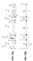
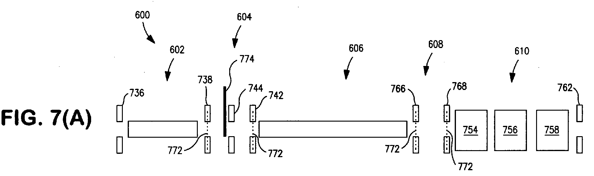
- Figure 7A is a more detailed schematic view of the MS apparatus illustrated in figure 6A .
- Figure 7B is a diagram illustrating the relative lengths and axial positions of components of the MS apparatus of figure 7A , and respective DC voltages and linear axial electric fields applied to these components, similar to figure 6B .
- Figure 8A is a cross-sectional view of one example of an ion accumulator, in the transverse plane perpendicular to a central axis of the ion accumulator, which may be included in the MS apparatus of figure 6A or 7A according to the present disclosure.
- Figure 8B is a side (lengthwise) view of the ion accumulator illustrated in figure 8A .
- Figure 9 is a side (lengthwise) view of a shutter assembly and adjacent regions of an ion accumulator and ion guide of the MS apparatus illustrated in figure 7A , and additionally showing the trajectories of ions.
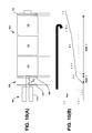
- Figure 10A is a side (lengthwise) view of the decelerator and detector cell of figure 7A , and the portion of the ion guide preceding the decelerator.
- Figure 10B illustrates an example of DC voltages that may be applied to electrodes of the ion guide, decelerator and detector cell of figure 10A when admitting ions into the detector cell from the accumulator, and also schematically illustrates the trajectory of the ions during this time.
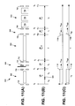
- Figure 11A is a schematic view of an MS apparatus similar to figure 7A .
- Figure 11B is a diagram illustrating the relative lengths and axial positions of an accumulator, shutter assembly, ion guide, decelerator and detector cell of the MS apparatus of figure 11A , and respective DC voltages and linear axial electric fields applied to these components, similar to figure 7B .
- Figure 11C is a diagram illustrating the axial positions at different times of two packets of ions of low mass and high mass processed by the MS apparatus of figure 11 A .
- Figure 12 is a plot of ion flight time through the MS apparatus illustrated in figure 11A , as a function of initial axial position for low mass ions and for high mass ions according to an implementation of the present disclosure.
- the electric fields utilized for acceleration/extraction and deceleration/retardation have a linear (axial) orientation, i.e., are formed by voltage gradients along the axis representing the general direction of ion flow from the accumulating trap to the detecting trap.
- These electric fields have a high degree of uniformity, i.e., their strengths (V/mm) are constant along the axis and in radial displacements from the axis.
- V/mm strengths
- Dual-stage uniform ion extraction field and/or a dual-stage uniform ion deceleration field are utilized.
- Dual-stage ion extraction from the accumulator may be utilized to bring all ions of the highest desirable mass to a space focus at or near the entrance of the detector cell, at the same time that most of the energy distribution of ions of the lowest desirable mass is located within the detector cell and traveling back in the direction toward the entrance of the detector cell.
- Dual-stage ion extraction from the accumulator may be utilized to transport ions of the same mass to a common space focus plane that may be located at an arbitrary distance from the accumulator.
- FIG. 6A is a schematic view of an example of a mass spectrometer (MS) apparatus 600 according to certain implementations of the present disclosure.
- the MS apparatus 600 generally includes an ion source (not shown) followed by an ion accumulator 602, a shutter assembly 604, an ion guide 606, an ion decelerator 608, and an ion detector cell 610 arranged in series about a central longitudinal axis.
- the enclosed vacuum regions, associated pumps, magnet assembly and other known components of the MS apparatus 600 are not shown for simplicity.
- the accumulator 602, ion guide 606, and detector cell 610 may be structured as described above in conjunction with figures 1-5 .
- the accumulator 602 and the ion guide 606 may be configured as linear (2D) multipole electrode sets with axial end electrodes for entrances and exits, and the detector cell 610 may include transmitter/detector plates between trapping rings and axial end electrodes.
- any suitable design may be selected for the ion source preceding the accumulator 602, particularly an atmospheric-pressure (AP) type source.
- AP atmospheric-pressure
- Continuous-beam sources particularly benefit from implementation of the present teachings, such as for example an electrospray ionization (ESI) source or an AP chemical ionization (APCI) source, although other ionizing devices such an AP photo-ionization source (APPI) or a matrix-assisted laser desorption ionization (MALDI) source may also be utilized.
- ESE electrospray ionization
- APCI AP chemical ionization
- APPI AP photo-ionization source
- MALDI matrix-assisted laser desorption ionization
- Figure 6B is a diagram illustrating the relative lengths and axial positions of the accumulator 602, shutter assembly 604, ion guide 606, decelerator 608 and detector cell 610, and respective DC voltages and linear axial electric fields applied to these components.
- point 0, point d 0 , point d 1 , point d SF , point d r1 and point d r2 are axial positions along the axis.
- Point 0 demarcates the entrance of the accumulator 602
- point d 0 demarcates the exit of the accumulator 602 and entrance of the shutter assembly 604
- point d 1 demarcates the exit of the shutter assembly 604 and entrance of the ion guide 606
- point d SF demarcates the exit of the ion guide 606 and entrance of the decelerator 608
- point d r2 demarcates the distal end of the detector cell 610.
- DC voltages are applied by suitable voltage sources (not shown) communicating with these components as follows: a voltage of V 0 is applied at point 0, a voltage of V 1 is applied at point d 0 , a voltage of V 2 is applied at point d 1 and point d SF , a voltage of V 3 is applied at point d r1 and a voltage of V 4 is applied at point d r2 .
- Figure 6B also depicts a packet of ions 664 trapped in the transverse plane by the RF field applied by the accumulator 602 located at an arbitrary point X 0 along the axis.
- S 0 is the distance along the axis of the ions 664 at point X 0 to the exit of the accumulator 602.
- the accumulator 602 has an axial length of d 0 (d 0 - 0).
- the shutter assembly 604 has an axial length of S 1 , or d 1 - d 0 .
- the ion guide 606 has an axial length of D, or d SF - d 1 .
- the decelerator 608 has an axial length of r1, or d r1 - d SF .
- the detector cell 610 has an axial length of r2, or d r2 - d r1 .
- Linear axial DC electric fields E 0 , E 1 , E D , E r1 and E r2 are applied across the respective axial lengths of the accumulator 602, shutter assembly 604, ion guide 606, decelerator 608 and detector cell 610.
- Ions are extracted from the accumulator 602 and transported into the detector cell 610 as follows. After the ions have been trapped in the accumulator 602 for a desired time, potential differences are respectively applied to generate the electric fields E 0 , E 1 , E r1 and E r2 .
- the electric fields E 0 and E 1 are extraction or accelerating fields and the electric fields E r1 and E r2 are decelerating or retarding fields.
- the ions are transported by the electric field E 0 from the accumulator 602 into the shutter assembly 604. In the shutter assembly 604 the ions are subjected to the second electric field E 1 and accelerated thereby to a final velocity.
- the electric field E 1 transports the ions into the axial field-free ion guide 606.
- the ions traverse the ion guide 606 and enter the decelerator 608 where they may be decelerated in the retarding electric field E r1 (which, in some implementations, may depend on the mass of the ions and timing, as described below).
- the ions then enter the detector cell 610 where they may be further decelerated in the second retarding electric field E r2 before being subsequently trapped in the detector cell 610 for mass analysis.
- Figure 7A is a more detailed schematic view of the MS apparatus 600 illustrated in figure 6A
- figure 7B is a diagram similar to figure 6B corresponding to this example.
- the accumulator 602 includes an ion entrance electrode 736 and an ion exit electrode 738 positioned at the opposing axial ends of the accumulator 602.
- the ion guide 606 includes an ion entrance electrode 742 and an ion exit electrode 766
- the detector cell 610 includes an ion entrance electrode 768 and an ion exit electrode 762.
- the axial electrodes 736, 738, 744, 742, 766, 768, 762 may be configured, for example, as lenses, i.e.
- the detector cell 610 may be configured as described above, i.e., include transmitter/detector electrodes 756 axially interposed between inner trapping electrodes 754, 758. Depending on design, the axial electrode 762 at the distal end of the detector cell 610 may or may not be utilized as an ion exit and thus may or may not include an aperture.
- Mesh grids 772 may be added to some or all of the apertures to provide more uniform electric fields for ion extraction and deceleration. That is, the grids 772 help to make the strengths of the electric fields more constant along the axis as well as in radial directions from the axis.
- the shutter assembly 604 includes a central apertured electrode 744 between the ion exit electrode 738 of the accumulator 602 and the ion entrance electrode 742 of the ion guide 606.
- the ion exit electrode 738 of the accumulator 602 may be considered as being the ion entrance into the shutter assembly 604 and the ion entrance electrode 742 of the ion guide 606 may be considered as being the ion exit from the shutter assembly 604.
- the shutter assembly 604 may be considered as including the ion exit electrode 738 of the accumulator 602 and the ion entrance electrode 742 of the ion guide 606, or as sharing these electrodes 738, 742 with the accumulator 602 and the ion guide 606.
- the shutter assembly 604 may also include a movable shutter element 774 as described earlier in this disclosure.
- the ion exit electrode 766 of the ion guide 606 may be considered as being the ion entrance into the decelerator 608 and the ion entrance electrode 768 of the detector cell 610 may be considered as being the ion exit from the decelerator 608.
- the decelerator 608 may be considered as including the ion exit electrode 766 of the ion guide 606 and the ion entrance electrode 768 of the detector cell 610, or as sharing these electrodes 766, 768 with the ion guide 606 and the detector cell 610.
- point 0 corresponds to the axial position of the ion entrance electrode 736 of the accumulator 602
- point d 0 corresponds to the axial position of the ion exit electrode 738 of the accumulator 602
- point d 1 corresponds to the axial position of the ion entrance electrode 742 of the ion guide 606
- point d SF corresponds to the axial position of the ion exit electrode 766 of the ion guide 606
- point d r1 corresponds to the axial position of the ion entrance electrode 768 of the detector cell 610
- point d r2 corresponds to the axial position of the ion exit electrode 762 of the detector cell 610.
- the axial lengths of the accumulator 602, shutter assembly 604, ion guide 606, decelerator 608 and detector cell 610 may be defined by these axial points as described above.
- controller i.e., one or more typically electronic processor-based control devices communicating with the various components as needed for controlling the application, timing and adjustment of the various RF and DC voltages, for coordinating the trapping and detecting operations of the detector cell 610 with other components of the MS apparatus 600, etc.
- Figure 8A is a cross-sectional view of another example of an ion accumulator 802, in the transverse plane perpendicular to a central axis 876, according to the present disclosure.
- Figure 8B is a side (lengthwise) view of the ion accumulator 802 according to this example.
- the accumulator 802 includes a plurality of electrodes 832 extending between a first axial end 836 and an opposing second axial end 838. For clarity, only two electrodes 832 are shown in figure 8B .
- the accumulator 802 typically includes six electrodes 832 (a hexapole arrangement) coaxially arranged about the central axis 876 at a radial distance therefrom.
- the term "radial” indicates a direction orthogonal to the central axis 876.
- the electrodes 832 are circumferentially spaced from each other in a transverse plane orthogonal to the central axis 876.
- the number of electrodes 832 may alternatively be eight (octopole) or more, or four (quadrupole).
- the accumulator 802 may generally include a housing or frame (not shown) or any other structure suitable for supporting the electrodes 832 in a fixed arrangement relative to the central axis 876, and for providing an evacuated, low-pressure environment suitable for trapping ions using radio frequency (RF) energy as described earlier.
- RF radio frequency
- the electrodes 832 circumscribe an interior space (ion trapping region) that likewise extends along the central axis 876 from the first axial end 836 to the second axial end 838.
- an appropriate RF (or RF/DC) voltage signal to the electrodes 832, the electrodes 832 generate a linear (2D) ion trapping field along the length of the accumulator 802 that constrains ions of a certain m/z range to radial motions focused along the central axis 876, whereby the ions occupy an axially elongated region cloud within the interior space.
- the RF voltage signal typically has a sinusoidal waveform although other periodic waveforms may be utilized as appreciated by persons skilled in the art.
- the RF voltage signal applied to any given electrode 832 is 180 degrees out-of-phase with the RF voltage signal applied to the circumferentially adjacent electrodes 832; that is, alternating electrodes 832 are driven out-of-phase with each other.
- the ion cloud may be further compressed by damping the motions of the ions through collisions with an inert collision gas, which may be introduced into the interior space from a gas source (not shown) by any suitable means.
- the ion guide 606 ( figure 7A ) may also be configured as a linear multipole electrode set in the manner just described for the accumulator 802.
- a multipole arrangement formed by a set of electrodes parallel to the axis is just one example of how to configure the accumulator 802 or the ion guide 606.
- Another example is a series of rings axially spaced from each and coaxially surrounding the axis.
- Another example is a set of helical electrodes coiled about the axis and running along the axis from the entrance end to the exit end.
- the accumulator 802 or the ion guide 606 may be configured to have any suitable linear geometry relative to the axis that is capable of applying a 2D RF trapping field and an appropriate axial DC field as described herein.
- FIGs 8A and 8B also illustrate one way in which the accumulator 802 may be configured for applying a uniform axial DC field E 0 in accordance with the present disclosure, as an alternative to simply applying voltages V 0 and V 1 to the ion entrance electrode and ion exit electrode, respectively.
- each electrode 832 is configured so as to contain a series of axially spaced electrically conductive segments that are electrically isolated from each other.
- each ion guide electrode 832 is formed from insulating rods 882 that are coated with axially spaced conductive (e.g., metal) bands 884.
- DC voltage sources may be placed in signal communication with each band 884 whereby the DC voltage on each individual band 884 is independently adjustable, while a common RF trapping voltage is applied to each band 884. This configuration enables the generation of an axial DC field E 0 with a highly controllable axial DC voltage gradient over the length of the accumulator 802.
- FIG. 8A and 8B Another alternative to the example shown in figures 8A and 8B is to divide the accumulator electrodes 832 into physically distinct axial segments separated by gaps, with each segment in signal communication with a DC voltage source, so long as inhomogeneous fields in the regions of the gaps do not interfere with the uniform axial DC field E 0 utilized to extract ions in accordance with the present teachings.
- a similar alternative is to divide two or more helical electrodes into axial segments and apply DC voltages to each segment.
- Another alternative is to provide the accumulator electrodes 832 as a series of rings and apply respective DC voltages to each ring. In all these cases, the accumulator electrodes 832 may be considered as including a series of axially spaced electrically conductive segments (axial segments, helical segments, rings, etc.).
- Figure 9 is a side (lengthwise) view of the shutter assembly 604 and adjacent regions of the ion accumulator 602 and ion guide 606, and additionally showing the trajectories of ions 986 as calculated by the commercially available SIMION® finite element ion simulation program (Scientific Instrument Services, Inc., Ringoes, New Jersey) during ion extraction from the accumulator 602.
- SIMION® finite element ion simulation program Saientific Instrument Services, Inc., Ringoes, New Jersey
- the accelerating field E 1 over the length of the shutter assembly 604 was established by the voltage V 1 applied to the axial electrode 738 between the accumulator 602 and the shutter assembly 604 and the voltage V 2 applied to the axial electrode 742 between the shutter assembly 604 and the ion guide 606.
- the apertures of the axial electrodes 738, 742 were covered with electrical grids 772 to improve the uniformity of the electric field E 1 between them.
- the central electrode 744 of the shutter assembly 604 was located at the axial midpoint of the shutter assembly (S 1 /2), whereby the central electrode 744 had a DC voltage of (V 2 - V 1 )/2.
- the ions 986 are transported through the accumulator 602 under the influence of its electric field E 0 and are accelerated in the field E 1 of the shutter assembly 604, whereby the ions 986 enter the ion guide 606 and travel toward the detector cell 610 ( figure 7A ).
- the gas pressure in the accumulator 602 may be increased for a short period of time to facilitate ion trapping and the reduction of kinetic energy spread by means of ion-gas molecule collisions.
- Figure 10A is a side (lengthwise) view of the decelerator 608, the detector cell 610, and the portion of the ion guide 606 preceding the decelerator 608.
- Figure 10B illustrates an example of the DC voltages that may be applied to the electrodes of the ion guide 606, decelerator 608 and detector cell 610 when admitting ions into the detector cell 610 from the accumulator 602, and also schematically illustrates the trajectory of the ions during this time.
- a DC voltage of -7 V is applied to the trapping electrodes 1034 and ion exit electrode 766 of the ion guide 606, a DC voltage of +5 V is applied to the ion entrance electrode 768 of the detector cell 610, a DC voltage of +6 V is applied to the first trapping electrode 754 of the detector cell 610, a DC voltage of +8 V is applied to the central electrode(s) 756 of the detector cell 610, a DC voltage of +10 V is applied to the second trapping electrode 758 of the detector cell 610, and a DC voltage of +11 V is applied to the ion exit electrode 762 of the detector cell 610.
- the voltages are arranged to form a two-stage uniform electric deceleration field, with the first deceleration field (E r1 ) applied over the length of the decelerator 608 and the second deceleration field (E r2 ) applied over the length of the detector cell 610.
- the geometry of the MS apparatus 600 (in particular the respective axial lengths of the accumulator 602, the shutter assembly 604 and the ion guide 606 ), and in turn the two-stage acceleration field applied to the accumulator 602 and shutter assembly 604, may be selected such that all (or substantially all) ions of the same mass (m/z ratio) initially stored in the accumulator 602 are transmitted into the detector cell 610 at the same time in response to activation of these acceleration fields, regardless of the initial axial position X 0 of the ions in the accumulator 602 at the time of activation of the acceleration fields.
- the additional selection of the respective axial lengths of the decelerator 608 and the detector cell 610 and the two-stage decelerating field applied thereto may ensure that the detector cell 610 is filled with the broadest mass range of ions desired to be analyzed, and the greatest number of such ions, during a very short filling time.
- Figure 11 illustrates an example of how to optimize filling the detector cell 610 with ions.
- figure 11A is a schematic view of an MS apparatus 600 similar to figure 7A .
- Figure 11B is a diagram illustrating the relative lengths and axial positions of the accumulator 602, shutter assembly 604, ion guide 606, decelerator 608 and detector cell 610, and respective DC voltages and linear axial electric fields applied to these components, similar to figure 7B .
- Figure 11C is a diagram illustrating the axial positions at different times of two packets of ions of low mass (m low ) and high mass (m high ).
- the low mass ions (m low ) may be considered as being the ions having the lowest mass desired to be analyzed in the detector cell 610
- the high mass ions (m high ) may be considered as being the ions having the highest mass desired to be analyzed in the detector cell 610. Therefore, it is desired that the detector cell 610 be efficiently filled with ions falling within a mass range from m low to m high . This range may include ions of mass m low , ions of mass m high , and any ions with masses falling between these two values, all of which were initially stored in the accumulator 602 prior to extraction.
- ions are injected into the accumulator 602 and trapped thereby they are initially distributed along the length of the accumulator trap 602, d 0 , as indicated by ion packets 1192 and 1194.
- a given ion's initial axial position X 0 in the accumulator 602 and consequently its initial axial distance S 0 from the exit of the accumulator 602 may be different than other ions of the same mass as well as ions of different masses.
- t 1 m 2 ⁇ e 1 / 2 ⁇ 2 ⁇ S 1 E 0 ⁇ S 0 + E 1 ⁇ S 1 1 / 2 + E 0 ⁇ S 0 1 / 2
- ⁇ ⁇ t 1 m 2 ⁇ eE 0 1 / 2 ⁇ ⁇ ⁇ S 0 S 0 1 / 2 ⁇ ⁇ 1 / 2 + ⁇ ⁇ S 0 1 / 2 2 ⁇ 2 ⁇ S 1
- ⁇ ⁇ t D m 2 ⁇ eE 0 1 / 2 ⁇ D ⁇ 1 / 2 - D ⁇ 0 1 / 2 + ⁇ ⁇ S 0 2 ⁇ ⁇ 1 / 2 1 / 2 ⁇ m 2 ⁇ eE 0 1 / 2 ⁇ ⁇ S 0 ⁇ D ⁇ 3 / 2
- Equation 18 is a statement that ions of the same mass that originate at different initial positions X 0 in the accumulator 602 will arrive close to the entrance to the detector cell 610 at point d SF at the same time.
- the plane located at point d SF can be considered to be a space focus plane.
- the space focus plane may be made to coincide with the exit aperture 766 by setting the geometry constraints D, S 0 , and S 1 and then using equation 19 to iteratively determine the electric field strengths E 0 and E 1 implicitly contained in d (defined above) that will place the space focus plane at this desired axial location. Ions initially located at the entrance of the accumulator 602 will spend more time in the electric field E 0 and will experience a larger potential change, and therefore will have a larger velocity than those ions initially located at the exit of the accumulator 602. Therefore after a period of time the ions initially located at the entrance will catch up to the ions initially located at the exit.
- the second electric field E 1 allows both sets of ions to be accelerated to an energy that allows the time required for the ions initially located at the entrance to catch up, i.e. position of the space focus plane, to be chosen over a large range of distances D from the exit d 1 of the shutter 604.
- all ions of the desired mass range will eventually be injected into the detector cell 610 and in a very short period of time. This is because at time t tot all ions of the desired mass range have been positioned somewhere between V 2 and V 4 (i.e., either in the decelerator 608 or in the detector cell 610 ), and at this time V 2 is increased as noted above to push all of the ions presently located in the decelerator 608 into the detector cell 610 and to prevent the low mass ions in the decelerator 608 (the ones that had been reflected in the detector cell 610 and are traveling back toward the space focus plane) from passing back through point d SF and escaping back into the ion guide 606.
- any ions in the region between V 2 and V 3 will be forced back into the region between V 3 and V 4 due to the electric field formed by the voltage difference between V 2 and V 3 .
- V 3 and V 4 it is then possible to adjust both V 3 and V 4 to further compress the ions along the axis into the center of the detector cell 610 (middle electrode segment 756 ) where they can be excited and detected by means known to persons skilled in the art. Because the ions are trapped in the axial direction by the voltages on V 2 and V 4 (the ions are always trapped in the radial direction by the magnetic field), the timing of these additional voltage changes is not critical.
- V 2 at time t tot such that V 2 > V 3 is tantamount to switching the first decelerating field E r1 to an accelerating field.
- the large mass ions all reach the space focus plane at the same time, time t tot , the large mass ions do not encounter the first decelerating field E r1 as it is switched to the accelerating field at this time.
- the first decelerating field E r1 is primarily important for slowing down the low mass ions in a short space so that the time required for them to reach their turning point in the second field region r 2 and be reflected back to V 2 is maximized. This allows the largest mass range possible to be simultaneously located between V 2 and V 4 .
- Low mass ions m low and high mass ions m high will both be focused at the space focus, but at different times.
- the low mass ions m low will have already have passed that point and proceeded into the retarding potential region E r2 of the detector cell 610.
- the retarding region E r2 the low mass ions m low will slow down, stop and reverse direction.
- the condition in which the greatest mass range can be trapped in the detector cell 610 will occur when at time t tot high mass ions m high will be located at the space focus plane and low mass ions m low will also be located there, but traveling in the opposite direction as indicated in figure 11 .
- the finite diameter of the electrodes will cause the field to be more non-uniform.
- the dimensions of the electrodes of an ICR-type detector cell are also constrained by requirements for ion excitation and detection that are more restrictive than those for ion trapping. Therefore r 1 and r 2 will generally be determined by detector cell design considerations and the choice of V 3 and V 4 will be determined by trapping requirement and mass range.
- the time t r1 required for ions to traverse r 1 can be obtained from the change in kinetic energy in the deceleration field E r1 :
- v d r ⁇ 1 eE r ⁇ 1 ⁇ r 1 + mv D 2 2 1 / 2 ⁇ 2 m 1 / 2
- t r ⁇ 1 m 2 1 / 2 2 eE r ⁇ 1 ⁇ eE r ⁇ 1 ⁇ r 1 + mv D 2 2 1 / 2 - mv D 2 2 1 / 2
- T Total t tot + 2 ⁇ t r ⁇ 1 + 2 ⁇ t t
- the electric fields are: Electrode Fields (Volts/mm)
- the flight time to the space focus plane is 1366.451 microseconds.
- the low mass ions, m/z 50 in the present example, travel faster and reach the space focus plane earlier with an average flight time of 203.327 microseconds and proceed to enter the retarding field of the detector cell 610 and are reflected from the repulsive potential back towards the entrance.
- figure 12 is a plot of ion flight time through the MS apparatus 600 as a function of initial axial position of the low mass ions and the high mass ions.
Landscapes
- Chemical & Material Sciences (AREA)
- Analytical Chemistry (AREA)
- Other Investigation Or Analysis Of Materials By Electrical Means (AREA)
- Electron Tubes For Measurement (AREA)
Abstract
Description
- The present invention relates generally to filling a mass analyzer with ions, particularly in a mass spectrometry apparatus that includes linearly arranged ion-processing components.
- Ion trapping mass spectrometers utilizing magnetic confinement of the ions in the radial direction and DC voltages for axial confinement are known as Penning Traps or ion cyclotron resonance mass spectrometers (ICR-MS). Ions in the trapping cell oscillate at a frequency that depends on the magnetic field strength and the mass-to-charge (m/z) ratio of the ion. Ions trapped in the detector cell can absorb energy by resonance excitation from an applied electrical field alternating at the frequency of oscillation of the ions, and can be detected by measuring the electromotive force (EMF) induced in the trapping cell walls due to the oscillating charge of the ions by means known in the art. Fourier Transform Mass Spectrometers (FTMS) detect the masses of ions by exciting the ions in the detector cell by means of a voltage pulse containing a range of frequencies or a rapid frequency scan so as to increase the energy of all of the ions present in the cell when the excitation frequency matches the ion oscillation frequency. The detected voltage is a complex mixture of frequencies that corresponds to the natural oscillation of all of the ions that were excited. A Fourier Transform of the time domain voltage results in a frequency domain spectrum that directly represents the mass and relative abundances of the ions present.
- Ions are generally formed in an ion source located outside of the magnetic field and must be accumulated in an ion trapping device and then transported into the detector cell and in the magnetic field. Since there is no inherent means of increasing the number of charged particles that are detected when detecting ions by induced EMF, as is common in other types of mass spectrometers which utilize electron multipliers, it is necessary to have a large-volume detector cell that can hold several million ions. Typically at least 100 ions are required for a minimum detectable voltage. It is known in the art to accumulate ions in a radio frequency (RF) ion trap comprising a multipole electrode structure, such as a hexapole or octopole, having RF voltages applied to the electrodes to confine the ions in the radial direction. DC voltages applied to apertures located on the axis of the accumulation trap and at the entrance and exit ends of the trap confine the ions in the axial direction.
-
Figure 1 is a schematic view of atypical FTMS system 100. In this schematic view, ions travel in a general direction from left to right along an axis about which various ion-controlling devices are arranged. TheFTMS system 100 generally includes an ion source (not shown) followed by, in succession along the axis, anion accumulator 102, ashutter assembly 104, anion guide 106, anion decelerator 108, and anion detector cell 110. The FTMSsystem 100 also includes a housing 112 that encloses theion accumulator 102, theshutter assembly 104, theion guide 106, theion decelerator 108 and theion detector cell 110. The housing 112 defines a first vacuum region (or pumping stage) 114 and a second vacuum region (or pumping stage) 116 adjoined at aboundary 118 having adifferential pumping aperture 120 located at the axis. Theion accumulator 102 and theshutter assembly 104 are positioned in thefirst pumping region 114 and theion guide 106, theion decelerator 108 and theion detector cell 110 are positioned in thesecond pumping region 116.Suitable vacuum pumps first vacuum region 114 at a vacuum pressure P1 and thesecond vacuum region 116 at a vacuum pressure P2 lower than P1. The FTMSsystem 100 further includes a suitable magnet assembly 126 (e.g., including a superconducting magnet) that coaxially surrounds theion detector cell 110 and may also surround theion decelerator 108 and part of theion guide 106. -
Figure 2A is a side (lengthwise) view of theion accumulator 102,shutter assembly 104 andion guide 106 illustrated infigure 1 . Theion accumulator 102 and theion guide 106 are typically structured as linear multipole electrode sets operating as ion traps. Each electrode set includes a set ofparallel electrodes electrodes 232, 234 (hexapole arrangement) or eightelectrodes 232, 234 (octopole arrangement). RF voltage sources (not shown) are connected to theelectrodes Respective lenses ion accumulator 102. Anotherlens 242 serves as the ion entrance to theion guide 106 and yet another lens (not shown) serves as the ion exit from theion guide 106. Thelenses shutter assembly 104 is typically a series oflenses 244 configured to direct the ions through thedifferential pumping aperture 120 located between the twovacuum regions 114 and 116 (figure 1 ). Theshutter 104 also typically includes a movable, mechanical shutter element (not shown). As an alternative to an RF multipole arrangement, theion guide 106 may be provided as a series of axially spaced DC lenses that would likewise operate to confine the ions in the radial direction as the ions travel to theion detector cell 110. - In operation,
ions 248 produced from a molecular sample in the ion source are transmitted in theion accumulator 102. In theion accumulator 102, the ions are confined in the radial direction by the RF voltages applied to theelectrodes 232 and in the axial direction by the DC voltages applied to theentrance lens 236 and theexit lens 238.Figure 2B illustrates typical DC voltages applied to theion accumulator 102,shutter assembly 104 andion guide 106 when trapping ions in theion accumulator 102. Assuming the ions are positively charged, a positive DC voltage (e.g., +5 V) is applied to theentrance lens 236, no DC voltage is applied to theelectrodes 232 of theion accumulator 102, a relatively higher DC voltage (e.g., +20 V) is applied to theexit lens 238, and a negative DC voltage (e.g., -7 V) is applied to theelectrodes 234 of theion guide 106. The low potential barrier at the entrance to theion accumulator 102 allows the ions to enter theion accumulator 102. The large potential barrier at the exit of theion accumulator 102 prevents ions from passing completely through theion accumulator 102 while the ions are being accumulated therein. The addition of a damping gas such as helium allows for the removal of excess kinetic energy by collisions so that the ions will not escape from theion accumulator 102 by leaving through the aperture of theentrance lens 236. -
Figures 3A and 3B illustrate the extraction of the ions from theion accumulator 102.Figure 3A is a side (lengthwise) view of theion accumulator 102,shutter assembly 104 andion guide 106 similar tofigure 2A , andfigure 3B illustrates typical DC voltages applied to theion accumulator 102,shutter assembly 104 andion guide 106 when extracting the trapped ions from theion accumulator 102. Ions are removed from theion accumulator 102 by reducing the potential barrier at theexit lens 238, for example by changing the DC voltage on theexit lens 238 from +20 V to -20 V as shown infigure 3B . Additionally, in prior art devices a large number of ions are accumulated so as to form space charge repulsion between the ions. The space charge repulsion, along with the attractive potential from theexit lens 238 of theion accumulator 102, causes ions to be removed from theion accumulator 102 and directed through theshutter assembly 104 and into theion guide 106. During ion extraction from theion accumulator 102, the shutter element of theshutter assembly 104 opens to allow ions to pass and closes after the ions have passed in order to reduce the gas load on thevacuum pump 124 in the second pumping region 116 (figure 1 ), thereby allowing lower pressures to be maintained during the succeeding mass analysis time. After traversing the differential pumping aperture 120 (figure 1 ), the ions then travel through theion guide 106.Ions 250 exiting theion guide 106 are decelerated and transmitted into the magnetic field and into theion detector cell 110. -
Figure 4A is a side (lengthwise) view of theion decelerator 108 andion detector cell 110 illustrated infigure 1 , as well as part of theion guide 106 preceding theion detector cell 110. Theion detector cell 110 typically includes three axially spacedelectrodes trapping plates trapping plate 108 at the ion entrance is typically a lens with an aperture, and typically serves as theion decelerator 108. Thecenter electrode 456 is further segmented into radial quadrants (not shown) so as to have pairs of opposing sections that can be utilized as transmitting and receiving electrodes for ion detection and mass measurement. In addition to applying alternating frequency voltages to theelectrodes electrode Figure 4B illustrates typical DC voltages applied to the various electrodes of theion guide 106,ion decelerator 108 andion detector cell 110 when admitting ions in theion detector cell 110, and also schematically illustrates the trajectory of the ions during this time. A negative DC voltage (e.g., -7 V) is applied to theelectrodes 234 of theion guide 106 as noted above, no DC voltage is applied to theion decelerator 108, a positive DC voltage (e.g., +0.2 V) is applied to the firstinner electrode 454, no DC voltage is applied to thecenter electrode 456, a positive DC voltage (e.g., +0.2 V) is applied to the secondinner electrode 458, and a positive DC voltage (e.g., +15 V) is applied to thedistal trapping plate 462. The voltage at the distal end of theion detector cell 110 has a repulsive DC potential applied to prevent the in-coming ions from escaping thedetector cell 110 at that end, as indicated schematically by the ion trajectory infigure 4B . Ions are confined in the radial direction by the magnetic field. The potential at the entrance (proximate) end of theion detector cell 110 is reduced so as to allow ions from theaccumulator trap 102 to enter thedetector cell 110 similar to what was described above for theaccumulator trap 102. Once the packet of ions has entered theion detector cell 110, the potential at the entrance is increased so as to prevent the ions in thedetector cell 110 from escaping from the entrance end. This is shown infigures 5A and 5B. Figure 5A is a side (lengthwise) view of theion decelerator 108,ion detector cell 110 and part of theion guide 106 similar tofigure 4A , andfigure 5B illustrates typical DC voltages applied to theion guide 106,ion decelerator 108 andion detector cell 110 when trapping the ions in theion detector cell 110.Figure 5B also schematically illustrates the trajectory of the ions during this time. The large potential barrier at the entrance to theion detector cell 110 is accomplished by changing the DC voltage on thedecelerator 108 from 0 V to +15 V. - Significant drawbacks are associated with conventional FTMS systems such described above and illustrated in
figures 1-5B . Ions traveling towards thedetector cell 110 from theaccumulator trap 102 begin to spread in space and time due to the differences in their masses and velocities. A further spreading of ions of the same mass will occur due to the energy variation of the ions due to the initial conditions and distribution of electric fields utilized to remove the ions from theaccumulator trap 102. Because of the spread of the ions in space and time it is difficult to efficiently transport ions of a large mass range into thedetector cell 110. Moreover, the reliance on the combination of ion space charge and a voltage differential between theaccumulator trap 102 and theexit aperture 238 causes a variable and highly non-linear ion extraction field that further degrades the efficiency and the mass range of ions capable of being trapped in thedetector cell 110. Furthermore, the electric field formed from the space charge changes as charge is removed from theaccumulator trap 102. Space charge forces are a function of mass in addition to the number of charges and their spatial distribution. Furthermore, adecelerator 108 in the form of a single lens at the entrance to thedetector 110 cannot produce a uniform electric field both along the axis and off the axis, but rather the field will be non-uniform, i.e. the strength (V/mm) of the field will not be constant. - In view of the foregoing, there is a need for more efficient methods and means for transporting ions from the accumulator trap into the detector cell. There is also a need for a method and apparatus that allow a larger mass range of ions to be simultaneously transported and trapped in the detector cell.
- To address the foregoing problems, in whole or in part, and/or other problems that may have been observed by persons skilled in the art, the present disclosure provides a method and a mass spectrometer apparatus as described by way of example in implementations set forth below.
- The invention is defined in
claims - According to one implementation, a method for filling an ion detector cell is provided. A plurality of ions, initially trapped in a linear-geometry ion accumulator, is transmitted from the ion accumulator to a shutter device by applying a first axial electric accelerating field across an axial length of the ion accumulator. The ions are transmitted through the shutter device and into a linear-geometry ion guide by applying a second axial electric accelerating field across an axial length of the shutter device. The ions are transmitted through the ion guide and into an ion decelerator. At least some of the ions are decelerated while being transmitted through the decelerator and into the ion detector cell by applying a first axial electric decelerating field across an axial length of the decelerator. At least some of the ions in the ion detector cell are decelerated by applying a second axial electric decelerating field across an axial length of the ion detector cell.
- According to another implementation, a method for filling an ion detector cell is provided. A plurality of ions, initially trapped in a linear-geometry ion accumulator and including at least a plurality of ions of a first mass, is transmitted from the ion accumulator to a shutter device by applying a first axial electric accelerating field of a first field strength across an axial length of the ion accumulator. The ions are transmitted through the shutter device and into a linear-geometry ion guide by applying a second axial electric accelerating field of a second field strength across an axial length of the shutter device. The ions are transmitted through the ion guide and into the ion detector cell. The first field strength, the second field strength, and the axial length of the ion accumulator, the axial length of the shutter device and an axial length of the ion guide, are selected such that all of the ions of the first mass are transmitted to an exit of the ion guide at the same time.
- Preferably the method, in particular the method according to any implementation, further comprises changing the first decelerating field to a third axial electric accelerating field applied over the axial length of the decelerator to transmit ions through the decelerator and into the ion detector cell.
- In the preferred embodiment according to
claim 7, applying the first accelerating field at the first field strength and applying the second accelerating field at a second field strength transmits all of the ions of same mass at any initial axial position to a space focus plane at the same time, and the space focus plane is located at an axial position between the ion guide and the ion detection cell. Further in an embodiment of this embodiment, the method further comprises positioning the space focus plane at an exit aperture of the ion guide; and/or in an embodiment of this embodiment, wherein applying the first accelerating field at the first field strength and applying the second accelerating field at the second field strength transmits all of the ions of same mass to the space focus plane at a time ttot, and further comprising, at the time ttot, changing the first decelerating field to a third axial electric accelerating field applied over the axial length of the decelerator to transmit the ions at the space focus plane and any ions between the space focus plane and the ion detector cell into the ion detector cell. - According to another implementation, a mass spectrometer apparatus includes a linear-geometry ion accumulator arranged along an axis, a shutter device axially succeeding the ion accumulator, a linear-geometry ion guide axially succeeding the shutter device, an ion decelerator axially succeeding the ion guide, and an ion detector cell axially succeeding the ion decelerator. The ion decelerator includes a first electrode having an aperture on the axis and a second electrode having an aperture on the axis and axially spaced from the first electrode. The apparatus may further include means for applying a first axial electric accelerating field across an axial length of the ion accumulator, and means for applying a second axial electric accelerating field across an axial length of the shutter device.
- According to another implementation, the mass spectrometer apparatus may further include means for applying a first axial electric decelerating field across an axial length of the decelerator, and means for applying a second axial electric decelerating field across an axial length of the ion detector cell. In yet another aspect, the mass spectrometer apparatus may further include means for switching the first decelerating field to a third accelerating field.
- According to another implementation, a mass spectrometer apparatus includes a linear-geometry ion accumulator arranged along an axis, a shutter device axially succeeding the ion accumulator, a linear-geometry ion guide axially succeeding the shutter device, an ion decelerator axially succeeding the ion guide, and an ion detector cell axially succeeding the ion decelerator. The apparatus may further include means for applying a first axial electric accelerating field across an axial length of the ion accumulator, means for applying a second axial electric accelerating field across an axial length of the shutter device, means for applying a first axial electric decelerating field across an axial length of the decelerator, and means for applying a second axial electric decelerating field across an axial length of the ion detector cell. In yet another aspect, the mass spectrometer apparatus may further include means for switching the first decelerating field to a third accelerating field.
- Preferably the mass spectrometer apparatus, in particular the mass spectrometer of
claim 15 and/or in any implementation, further comprises means for switching the first decelerating field to a third accelerating field. - The invention will be or will become apparent to one with skill in the art upon examination of the following figures and detailed description. It is intended that all such additional systems, methods, features and advantages be included within this description, be within the scope of the invention, and be protected by the accompanying claims.
- The invention can be better understood by referring to the following figures. The components in the figures are not necessarily to scale, emphasis instead being placed upon illustrating the principles of the invention. In the figures, like reference numerals designate corresponding parts throughout the different views.
-
Figure 1 is a schematic view of a typical Fourier Transform mass spectrometer (FTMS) system. -
Figure 2A is a side (lengthwise) view of an ion accumulator, shutter assembly and ion guide of the FTMS system illustrated infigure 1 . -
Figure 2B illustrates typical DC voltages applied to the ion accumulator, shutter assembly and ion guide offigure 2A when trapping ions in the ion accumulator. -
Figure 3A is a side (lengthwise) view of the ion accumulator, shutter assembly and ion guide similar tofigure 2A . -
Figure 3B illustrates typical DC voltages applied to the ion accumulator, shutter assembly and ion guide offigure 3A when extracting the trapped ions from the ion accumulator. -
Figure 4A is a side (lengthwise) view of the ion decelerator and ion detector cell illustrated infigure 1 , as well as part of the ion guide preceding the ion detector cell. -
Figure 4B illustrates typical DC voltages applied to the ion guide, ion decelerator and ion detector cell offigure 4A when admitting ions in the ion detector cell. -
Figure 5A is a side (lengthwise) view of the ion decelerator, ion detector cell and part of the ion guide similar tofigure 4A . -
Figure 5B illustrates typical DC voltages applied to the ion guide, ion decelerator and ion detector cell guide when trapping the ions in the ion detector cell. -
Figure 6A is a schematic view of an example of a mass spectrometer (MS) apparatus according to certain implementations of the present disclosure. -
Figure 6B is a diagram illustrating the relative lengths and axial positions of components of the MS apparatus offigure 6A , and respective DC voltages and linear axial electric fields applied to these components. -
Figure 7A is a more detailed schematic view of the MS apparatus illustrated infigure 6A . -
Figure 7B is a diagram illustrating the relative lengths and axial positions of components of the MS apparatus offigure 7A , and respective DC voltages and linear axial electric fields applied to these components, similar tofigure 6B . -
Figure 8A is a cross-sectional view of one example of an ion accumulator, in the transverse plane perpendicular to a central axis of the ion accumulator, which may be included in the MS apparatus offigure 6A or7A according to the present disclosure. -
Figure 8B is a side (lengthwise) view of the ion accumulator illustrated infigure 8A . -
Figure 9 is a side (lengthwise) view of a shutter assembly and adjacent regions of an ion accumulator and ion guide of the MS apparatus illustrated infigure 7A , and additionally showing the trajectories of ions. -
Figure 10A is a side (lengthwise) view of the decelerator and detector cell offigure 7A , and the portion of the ion guide preceding the decelerator. -
Figure 10B illustrates an example of DC voltages that may be applied to electrodes of the ion guide, decelerator and detector cell offigure 10A when admitting ions into the detector cell from the accumulator, and also schematically illustrates the trajectory of the ions during this time. -
Figure 11A is a schematic view of an MS apparatus similar tofigure 7A . -
Figure 11B is a diagram illustrating the relative lengths and axial positions of an accumulator, shutter assembly, ion guide, decelerator and detector cell of the MS apparatus offigure 11A , and respective DC voltages and linear axial electric fields applied to these components, similar tofigure 7B . -
Figure 11C is a diagram illustrating the axial positions at different times of two packets of ions of low mass and high mass processed by the MS apparatus offigure 11 A . -
Figure 12 is a plot of ion flight time through the MS apparatus illustrated infigure 11A , as a function of initial axial position for low mass ions and for high mass ions according to an implementation of the present disclosure. - As noted above, there is a need for more efficient methods and apparatus for transporting ions from the accumulator trap into the detector cell of an MS apparatus, and which also allow a larger mass range of ions to be simultaneously transported and trapped in the detector cell. In accordance with the present teachings, these goals may be obtained by applying an appropriate combination of electric fields utilized to extract ions from the accumulator trap and transport those ions into the detector cell, at appropriate locations of the MS apparatus and at appropriate times, and by selecting a proper choice of the dimensions and strengths of these electric fields. The electric fields utilized for acceleration/extraction and deceleration/retardation have a linear (axial) orientation, i.e., are formed by voltage gradients along the axis representing the general direction of ion flow from the accumulating trap to the detecting trap. These electric fields have a high degree of uniformity, i.e., their strengths (V/mm) are constant along the axis and in radial displacements from the axis. These electric fields are the predominant mechanism by which ions are extracted from the accumulating trap and collected in the detecting trap. Consequently, space-charge forces and other non-linear fields are not relied upon and the detecting trap can be filled with a maximum number of ions from a desired mass range. In certain implementations described below, a dual-stage uniform ion extraction field and/or a dual-stage uniform ion deceleration field are utilized. Dual-stage ion extraction from the accumulator may be utilized to bring all ions of the highest desirable mass to a space focus at or near the entrance of the detector cell, at the same time that most of the energy distribution of ions of the lowest desirable mass is located within the detector cell and traveling back in the direction toward the entrance of the detector cell. Dual-stage ion extraction from the accumulator may be utilized to transport ions of the same mass to a common space focus plane that may be located at an arbitrary distance from the accumulator.
-
Figure 6A is a schematic view of an example of a mass spectrometer (MS)apparatus 600 according to certain implementations of the present disclosure. TheMS apparatus 600 generally includes an ion source (not shown) followed by anion accumulator 602, ashutter assembly 604, anion guide 606, anion decelerator 608, and anion detector cell 610 arranged in series about a central longitudinal axis. The enclosed vacuum regions, associated pumps, magnet assembly and other known components of theMS apparatus 600 are not shown for simplicity. Theaccumulator 602,ion guide 606, anddetector cell 610 may be structured as described above in conjunction withfigures 1-5 . For example, theaccumulator 602 and theion guide 606 may be configured as linear (2D) multipole electrode sets with axial end electrodes for entrances and exits, and thedetector cell 610 may include transmitter/detector plates between trapping rings and axial end electrodes. Generally, any suitable design may be selected for the ion source preceding theaccumulator 602, particularly an atmospheric-pressure (AP) type source. Continuous-beam sources particularly benefit from implementation of the present teachings, such as for example an electrospray ionization (ESI) source or an AP chemical ionization (APCI) source, although other ionizing devices such an AP photo-ionization source (APPI) or a matrix-assisted laser desorption ionization (MALDI) source may also be utilized. -
Figure 6B is a diagram illustrating the relative lengths and axial positions of theaccumulator 602,shutter assembly 604,ion guide 606,decelerator 608 anddetector cell 610, and respective DC voltages and linear axial electric fields applied to these components. Infigure 6B ,point 0, point d0, point d1, point dSF, point dr1 and point dr2 are axial positions along the axis.Point 0 demarcates the entrance of theaccumulator 602, point d0 demarcates the exit of theaccumulator 602 and entrance of theshutter assembly 604, point d1 demarcates the exit of theshutter assembly 604 and entrance of theion guide 606, point dSF demarcates the exit of theion guide 606 and entrance of thedecelerator 608, point dr1 demarcates the exit of thedecelerator 608 and entrance of thedetector cell 610, and point dr2 demarcates the distal end of thedetector cell 610. DC voltages are applied by suitable voltage sources (not shown) communicating with these components as follows: a voltage of V0 is applied atpoint 0, a voltage of V1 is applied at point d0, a voltage of V2 is applied at point d1 and point dSF, a voltage of V3 is applied at point dr1 and a voltage of V4 is applied at point dr2.Figure 6B also depicts a packet ofions 664 trapped in the transverse plane by the RF field applied by theaccumulator 602 located at an arbitrary point X0 along the axis. S0 is the distance along the axis of theions 664 at point X0 to the exit of theaccumulator 602. Theaccumulator 602 has an axial length of d0 (d0 - 0). Theshutter assembly 604 has an axial length of S1, or d1 - d0. Theion guide 606 has an axial length of D, or dSF - d1. Thedecelerator 608 has an axial length of r1, or dr1 - dSF. Thedetector cell 610 has an axial length of r2, or dr2 - dr1. Linear axial DC electric fields E0, E1, ED, Er1 and Er2 are applied across the respective axial lengths of theaccumulator 602,shutter assembly 604,ion guide 606,decelerator 608 anddetector cell 610. In typical implementations of the present teachings, theion guide 606 is maintained in an axial electric field-free condition (ED = 0). - Ions are extracted from the
accumulator 602 and transported into thedetector cell 610 as follows. After the ions have been trapped in theaccumulator 602 for a desired time, potential differences are respectively applied to generate the electric fields E0, E1, Er1 and Er2. The electric fields E0 and E1 are extraction or accelerating fields and the electric fields Er1 and Er2 are decelerating or retarding fields. Thus, the ions are transported by the electric field E0 from theaccumulator 602 into theshutter assembly 604. In theshutter assembly 604 the ions are subjected to the second electric field E1 and accelerated thereby to a final velocity. The electric field E1 transports the ions into the axial field-free ion guide 606. The ions traverse theion guide 606 and enter thedecelerator 608 where they may be decelerated in the retarding electric field Er1 (which, in some implementations, may depend on the mass of the ions and timing, as described below). The ions then enter thedetector cell 610 where they may be further decelerated in the second retarding electric field Er2 before being subsequently trapped in thedetector cell 610 for mass analysis. -
Figure 7A is a more detailed schematic view of theMS apparatus 600 illustrated infigure 6A , andfigure 7B is a diagram similar tofigure 6B corresponding to this example. Theaccumulator 602 includes anion entrance electrode 736 and anion exit electrode 738 positioned at the opposing axial ends of theaccumulator 602. Theion guide 606 includes anion entrance electrode 742 and anion exit electrode 766, and thedetector cell 610 includes anion entrance electrode 768 and anion exit electrode 762. As appreciated by persons skilled in the art, theaxial electrodes detector cell 610 may be configured as described above, i.e., include transmitter/detector electrodes 756 axially interposed betweeninner trapping electrodes axial electrode 762 at the distal end of thedetector cell 610 may or may not be utilized as an ion exit and thus may or may not include an aperture.Mesh grids 772 may be added to some or all of the apertures to provide more uniform electric fields for ion extraction and deceleration. That is, thegrids 772 help to make the strengths of the electric fields more constant along the axis as well as in radial directions from the axis. Theshutter assembly 604 includes a centralapertured electrode 744 between theion exit electrode 738 of theaccumulator 602 and theion entrance electrode 742 of theion guide 606. Theion exit electrode 738 of theaccumulator 602 may be considered as being the ion entrance into theshutter assembly 604 and theion entrance electrode 742 of theion guide 606 may be considered as being the ion exit from theshutter assembly 604. As a physical component, theshutter assembly 604 may be considered as including theion exit electrode 738 of theaccumulator 602 and theion entrance electrode 742 of theion guide 606, or as sharing theseelectrodes accumulator 602 and theion guide 606. Theshutter assembly 604 may also include amovable shutter element 774 as described earlier in this disclosure. Theion exit electrode 766 of theion guide 606 may be considered as being the ion entrance into thedecelerator 608 and theion entrance electrode 768 of thedetector cell 610 may be considered as being the ion exit from thedecelerator 608. Thedecelerator 608 may be considered as including theion exit electrode 766 of theion guide 606 and theion entrance electrode 768 of thedetector cell 610, or as sharing theseelectrodes ion guide 606 and thedetector cell 610. In this example,point 0 corresponds to the axial position of theion entrance electrode 736 of theaccumulator 602, point d0 corresponds to the axial position of theion exit electrode 738 of theaccumulator 602, point d1 corresponds to the axial position of theion entrance electrode 742 of theion guide 606, point dSF corresponds to the axial position of theion exit electrode 766 of theion guide 606, point dr1 corresponds to the axial position of theion entrance electrode 768 of thedetector cell 610, and point dr2 corresponds to the axial position of theion exit electrode 762 of thedetector cell 610. The axial lengths of theaccumulator 602,shutter assembly 604,ion guide 606,decelerator 608 anddetector cell 610 may be defined by these axial points as described above. - It will be appreciated by persons skilled in the art that implicit in the schematic illustrations of
figures 6A and7A are the various RF and DC voltage sources in signal communication with the various electrodes as required to produce the electric fields being utilized. Also implicitly shown is a controller, i.e., one or more typically electronic processor-based control devices communicating with the various components as needed for controlling the application, timing and adjustment of the various RF and DC voltages, for coordinating the trapping and detecting operations of thedetector cell 610 with other components of theMS apparatus 600, etc. -
Figure 8A is a cross-sectional view of another example of anion accumulator 802, in the transverse plane perpendicular to acentral axis 876, according to the present disclosure.Figure 8B is a side (lengthwise) view of theion accumulator 802 according to this example. Theaccumulator 802 includes a plurality ofelectrodes 832 extending between a first axial end 836 and an opposing second axial end 838. For clarity, only twoelectrodes 832 are shown infigure 8B . Theaccumulator 802 typically includes six electrodes 832 (a hexapole arrangement) coaxially arranged about thecentral axis 876 at a radial distance therefrom. For purposes of the present disclosure, the term "radial" indicates a direction orthogonal to thecentral axis 876. Theelectrodes 832 are circumferentially spaced from each other in a transverse plane orthogonal to thecentral axis 876. The number ofelectrodes 832 may alternatively be eight (octopole) or more, or four (quadrupole). Theaccumulator 802 may generally include a housing or frame (not shown) or any other structure suitable for supporting theelectrodes 832 in a fixed arrangement relative to thecentral axis 876, and for providing an evacuated, low-pressure environment suitable for trapping ions using radio frequency (RF) energy as described earlier. Theelectrodes 832 circumscribe an interior space (ion trapping region) that likewise extends along thecentral axis 876 from the first axial end 836 to the second axial end 838. By applying an appropriate RF (or RF/DC) voltage signal to theelectrodes 832, theelectrodes 832 generate a linear (2D) ion trapping field along the length of theaccumulator 802 that constrains ions of a certain m/z range to radial motions focused along thecentral axis 876, whereby the ions occupy an axially elongated region cloud within the interior space. The RF voltage signal typically has a sinusoidal waveform although other periodic waveforms may be utilized as appreciated by persons skilled in the art. In a typical implementation the RF voltage signal applied to any givenelectrode 832 is 180 degrees out-of-phase with the RF voltage signal applied to the circumferentiallyadjacent electrodes 832; that is, alternatingelectrodes 832 are driven out-of-phase with each other. The ion cloud may be further compressed by damping the motions of the ions through collisions with an inert collision gas, which may be introduced into the interior space from a gas source (not shown) by any suitable means. The ion guide 606 (figure 7A ) may also be configured as a linear multipole electrode set in the manner just described for theaccumulator 802. - It will be understood that a multipole arrangement formed by a set of electrodes parallel to the axis is just one example of how to configure the
accumulator 802 or theion guide 606. Another example is a series of rings axially spaced from each and coaxially surrounding the axis. Another example is a set of helical electrodes coiled about the axis and running along the axis from the entrance end to the exit end. More generally, theaccumulator 802 or theion guide 606 may be configured to have any suitable linear geometry relative to the axis that is capable of applying a 2D RF trapping field and an appropriate axial DC field as described herein. -
Figures 8A and 8B also illustrate one way in which theaccumulator 802 may be configured for applying a uniform axial DC field E0 in accordance with the present disclosure, as an alternative to simply applying voltages V0 and V1 to the ion entrance electrode and ion exit electrode, respectively. Infigures 8A and 8B , eachelectrode 832 is configured so as to contain a series of axially spaced electrically conductive segments that are electrically isolated from each other. In the illustrated example, eachion guide electrode 832 is formed from insulatingrods 882 that are coated with axially spaced conductive (e.g., metal)bands 884. DC voltage sources (not shown) may be placed in signal communication with eachband 884 whereby the DC voltage on eachindividual band 884 is independently adjustable, while a common RF trapping voltage is applied to eachband 884. This configuration enables the generation of an axial DC field E0 with a highly controllable axial DC voltage gradient over the length of theaccumulator 802. - Another alternative to the example shown in
figures 8A and 8B is to divide theaccumulator electrodes 832 into physically distinct axial segments separated by gaps, with each segment in signal communication with a DC voltage source, so long as inhomogeneous fields in the regions of the gaps do not interfere with the uniform axial DC field E0 utilized to extract ions in accordance with the present teachings. A similar alternative is to divide two or more helical electrodes into axial segments and apply DC voltages to each segment. Another alternative is to provide theaccumulator electrodes 832 as a series of rings and apply respective DC voltages to each ring. In all these cases, theaccumulator electrodes 832 may be considered as including a series of axially spaced electrically conductive segments (axial segments, helical segments, rings, etc.). -
Figure 9 is a side (lengthwise) view of theshutter assembly 604 and adjacent regions of theion accumulator 602 andion guide 606, and additionally showing the trajectories ofions 986 as calculated by the commercially available SIMION® finite element ion simulation program (Scientific Instrument Services, Inc., Ringoes, New Jersey) during ion extraction from theaccumulator 602. Theaccumulator 602 and theion guide 600 had hexapole electrode configurations. The accelerating field E1 over the length of theshutter assembly 604 was established by the voltage V1 applied to theaxial electrode 738 between theaccumulator 602 and theshutter assembly 604 and the voltage V2 applied to theaxial electrode 742 between theshutter assembly 604 and theion guide 606. The apertures of theaxial electrodes electrical grids 772 to improve the uniformity of the electric field E1 between them. Thecentral electrode 744 of theshutter assembly 604 was located at the axial midpoint of the shutter assembly (S1/2), whereby thecentral electrode 744 had a DC voltage of (V2 - V1)/2. As described above, after trapping and gas damping by collisions, theions 986 are transported through theaccumulator 602 under the influence of its electric field E0 and are accelerated in the field E1 of theshutter assembly 604, whereby theions 986 enter theion guide 606 and travel toward the detector cell 610 (figure 7A ). The gas pressure in theaccumulator 602 may be increased for a short period of time to facilitate ion trapping and the reduction of kinetic energy spread by means of ion-gas molecule collisions. -
Figure 10A is a side (lengthwise) view of thedecelerator 608, thedetector cell 610, and the portion of theion guide 606 preceding thedecelerator 608.Figure 10B illustrates an example of the DC voltages that may be applied to the electrodes of theion guide 606,decelerator 608 anddetector cell 610 when admitting ions into thedetector cell 610 from theaccumulator 602, and also schematically illustrates the trajectory of the ions during this time. In this example, a DC voltage of -7 V is applied to thetrapping electrodes 1034 andion exit electrode 766 of theion guide 606, a DC voltage of +5 V is applied to theion entrance electrode 768 of thedetector cell 610, a DC voltage of +6 V is applied to thefirst trapping electrode 754 of thedetector cell 610, a DC voltage of +8 V is applied to the central electrode(s) 756 of thedetector cell 610, a DC voltage of +10 V is applied to thesecond trapping electrode 758 of thedetector cell 610, and a DC voltage of +11 V is applied to theion exit electrode 762 of thedetector cell 610. More generally, the voltages are arranged to form a two-stage uniform electric deceleration field, with the first deceleration field (Er1) applied over the length of thedecelerator 608 and the second deceleration field (Er2) applied over the length of thedetector cell 610. - Also in accordance with the present teachings, the geometry of the MS apparatus 600 (in particular the respective axial lengths of the
accumulator 602, theshutter assembly 604 and the ion guide 606), and in turn the two-stage acceleration field applied to theaccumulator 602 andshutter assembly 604, may be selected such that all (or substantially all) ions of the same mass (m/z ratio) initially stored in theaccumulator 602 are transmitted into thedetector cell 610 at the same time in response to activation of these acceleration fields, regardless of the initial axial position X0 of the ions in theaccumulator 602 at the time of activation of the acceleration fields. Additionally, in cases where ions of differing masses are initially stored in theaccumulator 602, the additional selection of the respective axial lengths of thedecelerator 608 and thedetector cell 610 and the two-stage decelerating field applied thereto may ensure that thedetector cell 610 is filled with the broadest mass range of ions desired to be analyzed, and the greatest number of such ions, during a very short filling time. -
Figure 11 illustrates an example of how to optimize filling thedetector cell 610 with ions. Specifically,figure 11A is a schematic view of anMS apparatus 600 similar tofigure 7A .Figure 11B is a diagram illustrating the relative lengths and axial positions of theaccumulator 602,shutter assembly 604,ion guide 606,decelerator 608 anddetector cell 610, and respective DC voltages and linear axial electric fields applied to these components, similar tofigure 7B .Figure 11C is a diagram illustrating the axial positions at different times of two packets of ions of low mass (mlow) and high mass (mhigh). For purposes of the present example, the low mass ions (mlow) may be considered as being the ions having the lowest mass desired to be analyzed in thedetector cell 610, and the high mass ions (mhigh) may be considered as being the ions having the highest mass desired to be analyzed in thedetector cell 610. Therefore, it is desired that thedetector cell 610 be efficiently filled with ions falling within a mass range from mlow to mhigh. This range may include ions of mass mlow, ions of mass mhigh, and any ions with masses falling between these two values, all of which were initially stored in theaccumulator 602 prior to extraction. As shown infigure 11C , after the ions are injected into theaccumulator 602 and trapped thereby they are initially distributed along the length of theaccumulator trap 602, d0, as indicated byion packets accumulator 602 and consequently its initial axial distance S0 from the exit of theaccumulator 602 may be different than other ions of the same mass as well as ions of different masses. The ions travel towards thedetector cell 610 when the extraction field, E0, is turned on at time t = 0. After a time ttot the high mass ions have traveled to the point dSF and the low mass ions have passed the point dSF, have been reflected by the potential V4 and are moving back in the direction of theaccumulator trap 602, as indicated byion packets figure 5 to fill and trap the ions in the range mlow to mhigh in thedetector cell 610. - As stated earlier, initially there is no axial electric field (E0 = 0) applied to the
accumulator 602. Thus, the ions are at rest, due to cooling of their kinetic energy by collisions, and are distributed along the axis of theaccumulator 602. At time t = 0 the electric field is changed to a value of E0. Ions located at point X0 will move to the end of theaccumulator 602. The time to required for ions initially located at point X0 to traverse the length S0 (move to the end of the accumulator 602) upon application of the extraction field E0 may be calculated as follows. - Time t0 in E0
- Generally, the change in kinetic energy (KE) experienced by an ion traveling in a linear direction from a
point 0 to a point x is: -

- where m is the mass of the ion and e is the electronic charge of the ion. Thus, the velocity of the ion at point x, vx, is:
-

- Applying these equations to the
accumulator 602 shown infigure 11A yields expressions for the velocity at point d0 and the time to required to reach d0: -

-

- Time t1 in E1
- By analogy to equations 1-4, the velocity at point d1, νd1, and the time t1 required to reach d1 are:
-

-

- As shown above, the velocity at point d1, νd1, is approximated to be equal to the velocity at point dSF, VD (disregarding any momentum losses), as no new axial electric field is applied in the ion guide 606 (ED = 0) in the present example.
- Time tD to travel distance D to point dSF
-

- Time ttot to travel distance S0+S1+D from point X0 to point dSF
-

- From equation 3, the time Δt0 required for an ion to travel through a small displacement of S0, or ΔS0, is:
-

- Expanding:
-

- Substituting the first order terms of
equation 10 into equation 9 yields: -

- From
equation 6 and substituting
-

- Expanding:
-

- Substituting the first order terms of equation 13 into equation 12 yields:
-

- From equation 7:
-

- Substituting the first order terms from equation 13 yields:
-

- Collecting terms from
equations 11, 12 and 16: -

- Adding the constraint that the time variation is independent of position X0 (or length S0) yields:
-

- Rearranging yields:
-

- This expression allows the choice of geometry parameters D, S0, and S1 and these then define δ and therefore the voltage requirements E1/E0. Equation 18 is a statement that ions of the same mass that originate at different initial positions X0 in the
accumulator 602 will arrive close to the entrance to thedetector cell 610 at point dSF at the same time. The plane located at point dSF can be considered to be a space focus plane. By choosing the location of the space focus plane to be coincident with theexit aperture 766 of theion guide 606, all ions of a given m/z can be at the entrance to thedetector cell 610 at the same time. The space focus plane may be made to coincide with theexit aperture 766 by setting the geometry constraints D, S0, and S1 and then using equation 19 to iteratively determine the electric field strengths E0 and E1 implicitly contained in d (defined above) that will place the space focus plane at this desired axial location. Ions initially located at the entrance of theaccumulator 602 will spend more time in the electric field E0 and will experience a larger potential change, and therefore will have a larger velocity than those ions initially located at the exit of theaccumulator 602. Therefore after a period of time the ions initially located at the entrance will catch up to the ions initially located at the exit. The second electric field E1 allows both sets of ions to be accelerated to an energy that allows the time required for the ions initially located at the entrance to catch up, i.e. position of the space focus plane, to be chosen over a large range of distances D from the exit d1 of theshutter 604. - Although the location of the space focus plane at point dSF does not place all of the ions in the
detector cell 610 at time ttot (as point dSF precedes the detector cell 610), changing the voltages at the axial ends of thedecelerator 608 such that V2 > V3 will ensure that ions initially in the region r1 are forced into the detector cell 610 a short time after ttot. Stated in another way, the space between V2 and V3 (or the decelerator 608) is not in thedetector cell 610, yet it is desired that all ions of a desired mass range originating in theaccumulator 602 be injected into the detector cell 610 (i.e., the space between V3 and V4). In accordance with the present teachings, all ions of the desired mass range will eventually be injected into thedetector cell 610 and in a very short period of time. This is because at time ttot all ions of the desired mass range have been positioned somewhere between V2 and V4 (i.e., either in thedecelerator 608 or in the detector cell 610), and at this time V2 is increased as noted above to push all of the ions presently located in thedecelerator 608 into thedetector cell 610 and to prevent the low mass ions in the decelerator 608 (the ones that had been reflected in thedetector cell 610 and are traveling back toward the space focus plane) from passing back through point dSF and escaping back into theion guide 606. Because this requires V2 to be greater than V3, any ions in the region between V2 and V3 will be forced back into the region between V3 and V4 due to the electric field formed by the voltage difference between V2 and V3. Once all the ions are between V3 and V4, it is then possible to adjust both V3 and V4 to further compress the ions along the axis into the center of the detector cell 610 (middle electrode segment 756) where they can be excited and detected by means known to persons skilled in the art. Because the ions are trapped in the axial direction by the voltages on V2 and V4 (the ions are always trapped in the radial direction by the magnetic field), the timing of these additional voltage changes is not critical. It will be noted that changing V2 at time ttot such that V2 > V3 is tantamount to switching the first decelerating field Er1 to an accelerating field. As conditions can be set such that the large mass ions all reach the space focus plane at the same time, time ttot, the large mass ions do not encounter the first decelerating field Er1 as it is switched to the accelerating field at this time. The first decelerating field Er1 is primarily important for slowing down the low mass ions in a short space so that the time required for them to reach their turning point in the second field region r2 and be reflected back to V2 is maximized. This allows the largest mass range possible to be simultaneously located between V2 and V4. - Low mass ions mlow and high mass ions mhigh will both be focused at the space focus, but at different times. By the time the high mass ions mhigh reach the space focus plane, the low mass ions mlow will have already have passed that point and proceeded into the retarding potential region Er2 of the
detector cell 610. Once in the retarding region Er2 the low mass ions mlow will slow down, stop and reverse direction. The condition in which the greatest mass range can be trapped in thedetector cell 610 will occur when at time ttot high mass ions mhigh will be located at the space focus plane and low mass ions mlow will also be located there, but traveling in the opposite direction as indicated infigure 11 . The value of mlow relative to mhigh is determined by r1, r2, V3 and V4. If r1 and r2 could be made arbitrarily large then the mass range that could be simultaneously located between V2 and V4 would be unbounded. However, this would require Er1 and Er2 to have the same values that they would have for smaller values of r1 and r2. This means that the voltages on V2, V3, and V4 would also have to be arbitrarily large (since the electric field is the voltage difference divided by the length, i.e. (V3 - V4)/r1 = Er1). Thus, there is a practical limit to the dimensions and voltages that can be utilized. For example as the lengths become larger, the finite diameter of the electrodes will cause the field to be more non-uniform. The dimensions of the electrodes of an ICR-type detector cell are also constrained by requirements for ion excitation and detection that are more restrictive than those for ion trapping. Therefore r1 and r2 will generally be determined by detector cell design considerations and the choice of V3 and V4 will be determined by trapping requirement and mass range. - The time tr1 required for ions to traverse r1 can be obtained from the change in kinetic energy in the deceleration field Er1:
-

-

- Integration of equation 21 yields:
-

- The time to reach the turning point tt in region r2 can be also found from the change in kinetic energy in the deceleration field Er2 and by recognizing that at the turning point the kinetic energy, (1/2)mvt 2 = 0; therefore:
-

- and

- Therefore the total time required for an ion to start at S0, travel to the
detector cell 610 and be reflected in region r2 and return to the space focus plane is: -

- This allows the calculation of the transit times as a function of mass and initial position. By way of example, for system dimensions of:
-


- And voltages of:
Electrode Voltages (Volts)
- The electric fields are:
Electrode Fields (Volts/mm)
- For ions of m/z=2000 originating at S0 = 30 mm at the center of the
accumulator 602, the flight time to the space focus plane is 1366.451 microseconds. For ions of this same high mass originating at the ends of theaccumulator 602, S0 = 6 mm and 54 mm, the flight time is found to be 1356.228 and 1356.717 microseconds respectively for a time difference of 0.489 microseconds. Traveling with a velocity of 1.0053 mm/microsecond, the spatial spread of the ions about the space focus plane is therefore 0.519 mm. The low mass ions, m/z = 50 in the present example, travel faster and reach the space focus plane earlier with an average flight time of 203.327 microseconds and proceed to enter the retarding field of thedetector cell 610 and are reflected from the repulsive potential back towards the entrance. At the time ttot that the high mass ions have just reached the space focus plane, the low mass ions originating at S0 = 54 mm at the entrance of theaccumulator 602 will have a flight time back to the space focus plane of 4065.022 microseconds, and the low mass ions originating at S0 = 8.4 mm at the exit end of theaccumulator 602 will have a flight time back to the space focus plane of 1364.02 microseconds. This result is shown infigure 12 , which is a plot of ion flight time through theMS apparatus 600 as a function of initial axial position of the low mass ions and the high mass ions. Hence, it can be seen in this example that all high mass ions originating in theaccumulator 602 located between S0 = 6 and 54 mm will be trapped and low mass ions between S0 = 8.4 and 54 mm will be trapped when the detector cell potentials are readjusted such as shown, for example, infigure 5 . - It will be understood that the methods and apparatus described in the present disclosure may be implemented in an ion processing system such as an MS system as generally described above by way of example. The present subject matter, however, is not limited to the specific ion processing systems illustrated herein or to the specific arrangement of circuitry and components illustrated herein.
- In general, terms such as "communicate" and "in ... communication with" (for example, a first component "communicates with" or "is in communication with" a second component) are used herein to indicate a structural, functional, mechanical, electrical, signal, optical, magnetic, electromagnetic, ionic or fluidic relationship between two or more components or elements. As such, the fact that one component is said to communicate with a second component is not intended to exclude the possibility that additional components may be present between, and/or operatively associated or engaged with, the first and second components.
- It will be understood that various aspects or details of the invention may be changed without departing from the scope of the invention. Furthermore, the foregoing description is for the purpose of illustration only, and not for the purpose of limitation-the invention being defined by the claims.
Claims (15)
- A method for filling an ion detector cell (610), the method comprising:transmitting a plurality of ions, initially trapped in a linear-geometry ion accumulator (602), from the ion accumulator to a shutter device (604) by applying a first axial electric accelerating field across an axial length of the ion accumulator (602);transmitting the ions through the shutter device (604) and into a linear-geometry ion guide (606) by applying a second axial electric accelerating field across an axial length of the shutter device (604);transmitting the ions through the ion guide (606) and into an ion decelerator (608);decelerating at least some of the ions while transmitting the ions through the decelerator (608) and into the ion detector cell (610) by applying a first axial electric decelerating field across an axial length of the decelerator; anddecelerating at least some of the ions in the ion detector cell (610) by applying a second axial electric decelerating field across an axial length of the ion detector cell.
- The method of claim 1, further comprising maintaining the ion guide (606) in an axial electric field-free state over an axial length thereof while transmitting the ions through the ion guide.
- The method of claim 1 or 2, wherein applying the first axial electric accelerating field comprises applying a plurality of DC voltages to a plurality of axially spaced conductive segments (884) of the accumulator (602).
- The method of claim 1, 2 or 3, further comprising applying the first accelerating field at a first field strength, applying the second accelerating field at a second field strength, and selecting the first field strength and the second field strength based on the axial lengths of the ion accumulator (602), the shutter device (604) and the ion guide (606).
- The method of claim 4, wherein selecting the first field strength and the second field strength is based on the following equation:

S0 is an axial distance from the initially trapped ions to an end of the accumulator (602) adjacent to the shutter device (604), S1 is the axial length of the shutter device (604), D is the axial length of the ion guide (606), E0 is the first field strength, and E1 is the second field strength. - The method of any of claims 1 to 5, wherein the plurality of ions initially trapped in the ion accumulator (602) comprise a plurality of ions of same mass located at different initial axial positions in the ion accumulator, and further comprising:applying the first accelerating field at a first field strength;applying the second accelerating field at a second field strength; andselecting the first field strength, the second field strength, and the axial lengths of the ion accumulator (602), the shutter device (604) and the ion guide (606), such that all of the ions of same mass at any initial axial position are transmitted to the ion detector cell (610) at the same time.
- The method of claim 6, wherein applying the first accelerating field at the first field strength and applying the second accelerating field at a second field strength transmits all of the ions of same mass at any initial axial position to a space focus plane at the same time, and the space focus plane is located at an axial position between the ion guide and the ion detection cell.
- The method of any of claims 1 to 7, wherein the plurality of ions initially trapped in the ion accumulator (602) comprise a plurality of ions of a highest mass desired to be trapped in the ion detector cell (610) and a plurality of ions of a lowest mass desired to be trapped in the ion detector cell, and further comprising:applying the first accelerating field at a first field strength;applying the second accelerating field at a second field strength; andselecting the first field strength, the second field strength, and the axial lengths of the ion accumulator (602), the shutter device (604) and the ion guide (606), such that at a time ttot, all of the ions of highest mass have been transmitted at the same time ttot to a space focus plane axially located between the ion guide (606) and the ion detector cell (610), and at the time ttot the ions of lowest mass have passed through the space focus plane, have entered the ion detector cell (610), and have been reflected back toward the space focus plane by the second decelerating field.
- The method of claim 8, further comprising, at the time ttot, changing the first decelerating field to a third axial electric accelerating field applied over the axial length of the decelerator (608) to transmit the ions of highest mass and lowest mass, located at the space focus plane and between the space focus plane and the ion detector cell, into the ion detector cell (610).
- A mass spectrometer apparatus (600), comprising:a linear-geometry ion accumulator (602) arranged along an axis;a shutter device (604) axially succeeding the ion accumulator (602);a linear-geometry ion guide (606) axially succeeding the shutter device (604); an ion decelerator (608) axially succeeding the ion guide (606) and comprising a first electrode (766) having an aperture on the axis and a second electrode (768) having an aperture on the axis and axially spaced from the first electrode (766);an ion detector cell (610) axially succeeding the ion decelerator (608);means (736, 738, 832) for applying a first axial electric accelerating field across an axial length of the ion accumulator (602); andmeans (738, 744, 742) for applying a second axial electric accelerating field across an axial length of the shutter device (604).
- The mass spectrometer apparatus of claim 10, wherein the ion accumulator (602) comprises a plurality of axially spaced electrically conductive segments (832), and the means (736, 738, 832) for applying the first accelerating field comprises means for applying DC voltages to the conductive segments.
- The mass spectrometer apparatus of claim 10 or 11, wherein the first electrode (766) and the second electrode (768) comprise mesh grids.
- The mass spectrometer apparatus of claim 10, 11 or 12, wherein the means (736, 738, 832) for applying the first accelerating field and the means (738, 744, 742) for applying the second accelerating field are configured for respectively applying a first field strength and a second field strength of respective values that cause all ions of a same given mass initially trapped in the accumulator (602) to be transmitted to an exit of the ion guide (606) at the same time.
- The mass spectrometer apparatus of any of claims 10 to 13, wherein the axial length of the accumulator (602), the axial length of the shutter device (604), and an axial length of the ion guide (606) have respective values that cause all ions of a same given mass initially trapped in the accumulator (602) to be transmitted to an exit of the ion guide at the same time in response to activation of the means (736, 738, 832) for applying the first accelerating field and the means (738, 744, 742) for applying the second accelerating field.
- The mass spectrometer apparatus of any of claims 10 to 14, further comprising means (766, 768) for applying a first axial electric decelerating field across an axial length of the decelerator (608), and means (754, 758; 768, 762) for applying a second axial electric decelerating field across an axial length of the ion detector cell (610).
Applications Claiming Priority (1)
| Application Number | Priority Date | Filing Date | Title |
|---|---|---|---|
| US12/547,335 US8309911B2 (en) | 2009-08-25 | 2009-08-25 | Methods and apparatus for filling an ion detector cell |
Publications (2)
| Publication Number | Publication Date |
|---|---|
| EP2299470A2 true EP2299470A2 (en) | 2011-03-23 |
| EP2299470A3 EP2299470A3 (en) | 2011-07-06 |
Family
ID=43413787
Family Applications (1)
| Application Number | Title | Priority Date | Filing Date |
|---|---|---|---|
| EP10008853A Withdrawn EP2299470A3 (en) | 2009-08-25 | 2010-08-25 | Methods and apparatus for filling an ion detector cell |
Country Status (3)
| Country | Link |
|---|---|
| US (1) | US8309911B2 (en) |
| EP (1) | EP2299470A3 (en) |
| CN (1) | CN102024660A (en) |
Cited By (2)
| Publication number | Priority date | Publication date | Assignee | Title |
|---|---|---|---|---|
| US8969794B2 (en) | 2013-03-15 | 2015-03-03 | 1St Detect Corporation | Mass dependent automatic gain control for mass spectrometer |
| US9035244B2 (en) | 2013-03-11 | 2015-05-19 | 1St Detect Corporation | Automatic gain control with defocusing lens |
Families Citing this family (5)
| Publication number | Priority date | Publication date | Assignee | Title |
|---|---|---|---|---|
| US8461521B2 (en) * | 2010-12-14 | 2013-06-11 | Virgin Instruments Corporation | Linear time-of-flight mass spectrometry with simultaneous space and velocity focusing |
| KR101239747B1 (en) * | 2010-12-03 | 2013-03-06 | 한국기초과학지원연구원 | Fourier transform ion cyclotron resonance mass spectrometer and method for concentrating ions for fourier transform ion cyclotron resonance mass spectrometry |
| US10224194B2 (en) * | 2016-09-08 | 2019-03-05 | Battelle Memorial Institute | Device to manipulate ions of same or different polarities |
| US10332723B1 (en) | 2017-12-20 | 2019-06-25 | Battelle Memorial Institute | Ion focusing device |
| US10665441B2 (en) * | 2018-08-08 | 2020-05-26 | Thermo Finnigan Llc | Methods and apparatus for improved tandem mass spectrometry duty cycle |
Family Cites Families (12)
| Publication number | Priority date | Publication date | Assignee | Title |
|---|---|---|---|---|
| US4686365A (en) * | 1984-12-24 | 1987-08-11 | American Cyanamid Company | Fourier transform ion cyclothon resonance mass spectrometer with spatially separated sources and detector |
| AU6653296A (en) * | 1995-08-11 | 1997-03-12 | Mds Health Group Limited | Spectrometer with axial field |
| US6130426A (en) | 1998-02-27 | 2000-10-10 | Bruker Daltonics, Inc. | Kinetic energy focusing for pulsed ion desorption mass spectrometry |
| US6417511B1 (en) * | 2000-07-17 | 2002-07-09 | Agilent Technologies, Inc. | Ring pole ion guide apparatus, systems and method |
| GB2399450A (en) | 2003-03-10 | 2004-09-15 | Thermo Finnigan Llc | Mass spectrometer |
| JP4284167B2 (en) * | 2003-12-24 | 2009-06-24 | 株式会社日立ハイテクノロジーズ | Accurate mass measurement method using ion trap / time-of-flight mass spectrometer |
| GB2412486B (en) * | 2004-03-26 | 2009-01-14 | Thermo Finnigan Llc | Fourier transform mass spectrometer and method for generating a mass spectrum therefrom |
| US8847153B2 (en) * | 2005-01-17 | 2014-09-30 | Micromass Uk Limited | Segmented ion trap mass spectrometer |
| EP1688986A1 (en) | 2005-02-02 | 2006-08-09 | Max-Planck-Gesellschaft zur Förderung der Wissenschaften e.V. | Method and device for transferring ions in a mass spectrometer |
| US7557343B2 (en) * | 2005-09-13 | 2009-07-07 | Agilent Technologies, Inc. | Segmented rod multipole as ion processing cell |
| DE102007017236B4 (en) | 2007-04-12 | 2011-03-31 | Bruker Daltonik Gmbh | Introduction of ions into a magnetic field |
| US7629575B2 (en) | 2007-12-19 | 2009-12-08 | Varian, Inc. | Charge control for ionic charge accumulation devices |
-
2009
- 2009-08-25 US US12/547,335 patent/US8309911B2/en active Active
-
2010
- 2010-08-25 EP EP10008853A patent/EP2299470A3/en not_active Withdrawn
- 2010-08-25 CN CN2010102679485A patent/CN102024660A/en active Pending
Non-Patent Citations (1)
| Title |
|---|
| None |
Cited By (3)
| Publication number | Priority date | Publication date | Assignee | Title |
|---|---|---|---|---|
| US9035244B2 (en) | 2013-03-11 | 2015-05-19 | 1St Detect Corporation | Automatic gain control with defocusing lens |
| US8969794B2 (en) | 2013-03-15 | 2015-03-03 | 1St Detect Corporation | Mass dependent automatic gain control for mass spectrometer |
| US9472388B2 (en) | 2013-03-15 | 2016-10-18 | 1St Detect Corporation | Mass dependent automatic gain control for mass spectrometer |
Also Published As
| Publication number | Publication date |
|---|---|
| US20110049346A1 (en) | 2011-03-03 |
| CN102024660A (en) | 2011-04-20 |
| US8309911B2 (en) | 2012-11-13 |
| EP2299470A3 (en) | 2011-07-06 |
Similar Documents
| Publication | Publication Date | Title |
|---|---|---|
| US10796893B2 (en) | RF ion guide with axial fields | |
| EP1704578B1 (en) | Ion extraction devices and methods of selectively extracting ions | |
| US7405401B2 (en) | Ion extraction devices, mass spectrometer devices, and methods of selectively extracting ions and performing mass spectrometry | |
| US7285774B2 (en) | FAIMS apparatus and method for separating ions in the gas phase | |
| JP5301285B2 (en) | Focused mass spectrometer ion guide, spectrometer and method | |
| US7019285B2 (en) | Ion storage time-of-flight mass spectrometer | |
| US6020586A (en) | Ion storage time-of-flight mass spectrometer | |
| US6417511B1 (en) | Ring pole ion guide apparatus, systems and method | |
| EP0904145B1 (en) | Ion transfer from multipole ion guides into multipole ion guides and ion traps | |
| US8309911B2 (en) | Methods and apparatus for filling an ion detector cell | |
| US8637816B1 (en) | Systems and methods for MS-MS-analysis | |
| US8916819B2 (en) | Method and apparatus for improving the throughput of a charged particle analysis system | |
| US12119214B2 (en) | Ion guide with varying multipoles | |
| US8946625B2 (en) | Introduction of ions into a magnetic field | |
| WO2023028696A1 (en) | Method and apparatus to increase sensitivity of inductively coupled plasma mass spectrometry | |
| CN115116818A (en) | Dual frequency RF ion confinement device | |
| US9536723B1 (en) | Thin field terminator for linear quadrupole ion guides, and related systems and methods | |
| CA2491198C (en) | Ion storage time-of-flight mass spectrometer | |
| JP2005032476A (en) | Mass spectrometer |
Legal Events
| Date | Code | Title | Description |
|---|---|---|---|
| PUAI | Public reference made under article 153(3) epc to a published international application that has entered the european phase |
Free format text: ORIGINAL CODE: 0009012 |
|
| AK | Designated contracting states |
Kind code of ref document: A2 Designated state(s): AL AT BE BG CH CY CZ DE DK EE ES FI FR GB GR HR HU IE IS IT LI LT LU LV MC MK MT NL NO PL PT RO SE SI SK SM TR |
|
| AX | Request for extension of the european patent |
Extension state: BA ME RS |
|
| PUAL | Search report despatched |
Free format text: ORIGINAL CODE: 0009013 |
|
| AK | Designated contracting states |
Kind code of ref document: A3 Designated state(s): AL AT BE BG CH CY CZ DE DK EE ES FI FR GB GR HR HU IE IS IT LI LT LU LV MC MK MT NL NO PL PT RO SE SI SK SM TR |
|
| AX | Request for extension of the european patent |
Extension state: BA ME RS |
|
| RIC1 | Information provided on ipc code assigned before grant |
Ipc: H01J 49/06 20060101ALI20110530BHEP Ipc: H01J 49/04 20060101ALI20110530BHEP Ipc: H01J 49/38 20060101AFI20110110BHEP |
|
| 17P | Request for examination filed |
Effective date: 20120109 |
|
| STAA | Information on the status of an ep patent application or granted ep patent |
Free format text: STATUS: THE APPLICATION IS DEEMED TO BE WITHDRAWN |
|
| 18D | Application deemed to be withdrawn |
Effective date: 20160301 |