EP2299224A2 - Heat exchanger with headers and distribution tube - Google Patents
Heat exchanger with headers and distribution tube Download PDFInfo
- Publication number
- EP2299224A2 EP2299224A2 EP10009474A EP10009474A EP2299224A2 EP 2299224 A2 EP2299224 A2 EP 2299224A2 EP 10009474 A EP10009474 A EP 10009474A EP 10009474 A EP10009474 A EP 10009474A EP 2299224 A2 EP2299224 A2 EP 2299224A2
- Authority
- EP
- European Patent Office
- Prior art keywords
- distribution
- heat exchanger
- distribution tube
- refrigerant
- exchanger according
- Prior art date
- Legal status (The legal status is an assumption and is not a legal conclusion. Google has not performed a legal analysis and makes no representation as to the accuracy of the status listed.)
- Granted
Links
Images




Classifications
-
- F—MECHANICAL ENGINEERING; LIGHTING; HEATING; WEAPONS; BLASTING
- F28—HEAT EXCHANGE IN GENERAL
- F28F—DETAILS OF HEAT-EXCHANGE AND HEAT-TRANSFER APPARATUS, OF GENERAL APPLICATION
- F28F9/00—Casings; Header boxes; Auxiliary supports for elements; Auxiliary members within casings
- F28F9/02—Header boxes; End plates
- F28F9/026—Header boxes; End plates with static flow control means, e.g. with means for uniformly distributing heat exchange media into conduits
- F28F9/027—Header boxes; End plates with static flow control means, e.g. with means for uniformly distributing heat exchange media into conduits in the form of distribution pipes
- F28F9/0273—Header boxes; End plates with static flow control means, e.g. with means for uniformly distributing heat exchange media into conduits in the form of distribution pipes with multiple holes
-
- F—MECHANICAL ENGINEERING; LIGHTING; HEATING; WEAPONS; BLASTING
- F28—HEAT EXCHANGE IN GENERAL
- F28D—HEAT-EXCHANGE APPARATUS, NOT PROVIDED FOR IN ANOTHER SUBCLASS, IN WHICH THE HEAT-EXCHANGE MEDIA DO NOT COME INTO DIRECT CONTACT
- F28D1/00—Heat-exchange apparatus having stationary conduit assemblies for one heat-exchange medium only, the media being in contact with different sides of the conduit wall, in which the other heat-exchange medium is a large body of fluid, e.g. domestic or motor car radiators
- F28D1/02—Heat-exchange apparatus having stationary conduit assemblies for one heat-exchange medium only, the media being in contact with different sides of the conduit wall, in which the other heat-exchange medium is a large body of fluid, e.g. domestic or motor car radiators with heat-exchange conduits immersed in the body of fluid
- F28D1/04—Heat-exchange apparatus having stationary conduit assemblies for one heat-exchange medium only, the media being in contact with different sides of the conduit wall, in which the other heat-exchange medium is a large body of fluid, e.g. domestic or motor car radiators with heat-exchange conduits immersed in the body of fluid with tubular conduits
- F28D1/053—Heat-exchange apparatus having stationary conduit assemblies for one heat-exchange medium only, the media being in contact with different sides of the conduit wall, in which the other heat-exchange medium is a large body of fluid, e.g. domestic or motor car radiators with heat-exchange conduits immersed in the body of fluid with tubular conduits the conduits being straight
Definitions
- the present invention relates to a heat exchanger.
- a heat exchanger generally comprises an inlet header, an outlet header, tubes and fins.
- a tubular distributor is generally inserted into the inlet header. The refrigerant enters into the distributor from a refrigerant source and then is distributed into the interior of the header.
- the distributor 1' of a conventional heat exchanger is inserted into the refrigerant within the inlet header 2', so that the distributor 1' is difficult to assemble and disassemble.
- the distributor 1' and the refrigerant in the inlet header 2' disadvantageously disturbs each other.
- the number of the distributor 1' disposed in the inlet header 2' is limited, so that the distributed amount of the refrigerant is difficult to control.
- the present invention is directed to solve at least one of the problems exiting in the prior art.
- an object of the present invention is to provide a heat exchanger, in which the assembling and disassembling of the distribution tube of the heat exchanger is simple, the distribution tube is easy to maintain, and the refrigerants in the inlet header and the distribution tube do not affect disadvantageously each other.
- An embodiment of the present invention provides a heat exchanger, comprising: an inlet header defining a refrigerant chamber therein; an outlet header spaced apart from the inlet header; a plurality of tubes, two ends of each tube being connected and communicated with the inlet and outlet headers respectively; a plurality of fins, each of which is interposed between adjacent tubes, and a distribution tube disposed outside the refrigerant chamber and formed with a distribution opening, through which the distribution tube is communicated with the refrigerant chamber.
- the distribution tube since the distribution tube is not inserted into the refrigerant within the inlet header, the distribution tube is easy to assemble, disassemble and maintain, the refrigerant in the inlet header and the distribution tube do not affect disadvantageously each other, thus enhancing distribution of the refrigerant.
- the distribution tube is mounted onto an outer wall of the inlet header. Therefore, it is easier to assemble, disassemble and maintain the distribution tube.
- the distribution tube is formed integrally with a mounting foot, through which the distribution tube is mounted onto the outer wall of the inlet header.
- a partition is disposed inside the inlet header so as to divide an interior of the inlet header into the refrigerant chamber and a cavity isolated from each other.
- the interior of the inlet header is divided into two portions by the partition, resulting in reduction of volume of the refrigerant chamber, which can further enhance distribution of the refrigerant.
- a ratio of an inner diameter of the distribution tube to a hydraulic inner diameter of the refrigerant chamber is within a range of about 0.17 - about 0.79.
- the distribution tube is disposed inside the cavity.
- the heat exchanger according to the embodiment of the present invention further comprises communication pipe, a first end of which is connected to the distribution tube so as to communicate with the distribution tube via the distribution opening and a second end thereof is communicated with the refrigerant chamber.
- the distribution opening comprises a plurality of orifices formed in the distribution tube and separated from each other.
- the distribution opening comprises a single slot formed in the distribution tube.
- the distribution opening is circular and a hydraulic diameter thereof is in a range of about 0.2- about 4mm.
- a ratio of an area of the distribution opening to a cross sectional area of the refrigerant chamber is within a range of from about 0.3to about 2.
- a plurality of the distribution tubes are disposed.
- the distribution tube may be plural, by controlling individual distribution tubes, it is easy to control the distribution amount of the refrigerant and satisfy the different requirements for the amount of the refrigerant.
- a flow direction of a refrigerant in the tubes is at an angle of about 45°-about 315°with an opposite direction to an outflow direction of the refrigerant discharged from the distribution opening, thus enhancing distribution of the refrigerant.
- the heat exchanger according to an embodiment of the present invention comprises an inlet header 2, an outlet header 6, tubes 3, fins 7 and a distribution tube 1.
- the inlet header 2 defines a refrigerant chamber S1 therein.
- the whole inner chamber of the inlet header 2 is the refrigerant chamber S1.
- a partition is disposed inside the inlet header so as to divide an interior of the inlet header into the refrigerant chamber S1 and a cavity S2 isolated from each other (which will be described below).
- the outlet header 6 and the inlet header 2 are spaced apart from each other, and for example, disposed substantially parallelly to each other.
- Two ends of each tube are connected and communicated with the inlet and outlet headers 2, and 6 respectively, for example by welding, such that the inlet header 2 is communicated with the outlet header 6 via refrigerant channels in tubes 3.
- the refrigerant channel of tube 3 may be a micro-channel for instance, therefore the heat exchanger is referred to as a micro-channel heat exchanger.
- Each fin is disposed between adjacent tubes so as to enhance the effect of heat transfer.
- a distribution opening 14 is formed in the distribution tube 1.
- the distribution tube 1 is disposed outside the refrigerant chamber S1, and an inner chamber 13 of the distribution tube 1 is communicated with the refrigerant chamber S1 via the distribution opening 14.
- a through hole 21 is formed accordingly in a wall of the inlet header 2 defining the refrigerant chamber S1.
- the distribution tube 1 is not disposed in the refrigerant chamber S1 of the inlet header 2.
- the distribution tube 1 is not inserted into the refrigerant within the inlet header 2. Therefore, assembling and disassembling of the distribution tube 1 are simple, the distribution tube 1 is easy to maintain, and the refrigerants in the inlet header 2 and the distribution tube 1 do not affect disadvantageously each other, thus enhancing distribution of the refrigerant.
- the distribution tube 1 is mounted onto the outer wall of the inlet header 2 and the distribution opening 14 corresponds to the through hole 21. Therefore, the refrigerant, which enters into the inner chamber 13 of the distribution tube 1 from a refrigerant source (not shown), is sprayed into the refrigerant chamber S1 via the distribution opening 14 and the through hole 21, thus eliminating the separation of vapor refrigerant and liquid refrigerant in the inlet header 2 and enhancing the effect of heat transfer.
- a ratio of an inner diameter of the distribution tube 1 to a hydraulic inner diameter of the refrigerant chamber S1 is within a range of about 0.17 - about 0.79.
- the distribution tube 1 is formed integrally with a mounting foot 12 having a surface adapted to outer surface of inlet header 2, so that the distribution tube 1 is fixed onto the outer wall of the inlet header 2, for example, by welding the mounting foot 12 to the outer wall of the inlet header 2.
- the distribution opening 14 is penetrated through the mounting foot 12 and corresponded to the through hole 21.
- the distribution opening 14 comprises a plurality of orifices formed in the distribution tube 1 separated from each other.
- the orifice may be a circular orifice or a slot having any other shapes.
- the distribution opening 14 may be formed as a single slot extending along the longitudinal direction of the distribution tube 1.
- the distribution opening 14 is circular and its hydraulic diameter is within a range of from about 0.2 to about 4 mm, thus further improving the heat transfer effect.
- a ratio of an area of the distribution opening 14 to a cross sectional area of the refrigerant chamber S1 is within the range of from about 0.3 to about 2.
- the number of the distribution tube 1 is easy to change.
- the number of the inlet header 2 may be several so as to satisfy the requirements of the heat exchanger for different amount of refrigerant, and the distribution of the refrigerant is easy to control by controlling individual distribution tubes 1.
- an opposite direction B to an outflow direction of the refrigerant discharged from the distribution opening 14 is at an angle of about 45 °- about 315 ° with a flow direction A of a refrigerant in the tubes 3.
- the distributing effect of the refrigerant is further enhanced by setting the angle between the direction A and B in the above angle range.
- the direction B is at an angle of 180°with the direction A.
- the direction B is at an angle of 90°with the direction A.
- the distribution tube 1 without the mounting foot 12 thereon is connected and communicated with the refrigerant chamber S1 of the inlet header 2 via a communication pipe 5 rather than the mounting foot 12.
- a first end of the communication pipe 5 is welded to the distribution tube 1 at the position of the distribution tube 14, and a second end thereof is extended into the refrigerant chamber S1 penetrated through the wall of the inlet header 2.
- the joint of the communication pipe 5 and the inlet header 2 is sealed, for example, via welding the communication pipe 5 to the inlet header 2, that is, the gap between the communication pipe 5 and the inlet header 2 is sealed.
- a partition 4 is disposed inside the inlet header 2 so as to divide the interior of the inlet header 2 into the refrigerant chamber S1 and a cavity S2 isolated from each other. There will be no refrigerants in the cavity S2, and the distribution tube 1 is fixed onto the outer wall of the inlet header 2 and communicated with the refrigerant chamber S1 via the distribution opening 14 and the through hole 21.
- the provision of the partition 4 reduces the volume of the refrigerant chamber S1, thus further enhancing distribution of the refrigerant.
- the distribution tube 1 is formed with the mounting foot, so that the distribution tube 1 may be fixed conveniently onto the outer wall of the inlet header 2 .
- Fig. 6 shows an alternative embodiment of the present invention.
- the distribution tube 1 is disposed inside the cavity S2 rather than fixed onto the outer wall of the inlet header 2 and communicated with the refrigerant chamber S1 via the communication pipe 5. Therefore, the distribution tube 1 is easy to assemble and disassemble, and is not affected by the refrigerant in the inlet header 2. Meanwhile, the volume of the refrigerant chamber S1 is reduced, thus improving the distributing effect of the refrigerant and improving the aesthetics of the heat exchanger.
- the refrigerant enters into the distribution tube 1 along the direction C, and then sprays into the refrigerant chamber S1 of the inlet header 2 via the distribution opening 14, thus eliminating the separation of vapor refrigerant and liquid refrigerant in the two-phase flow, and finally the refrigerant flows towards the outlet header 6 along the tubes 3 and exchanges heat during this period.
- the refrigerant subject to heat exchanging enters into the outlet header 6 and is finally discharged from the outlet header 6 along the direction D.
- the distribution tube 1 Since the distribution tube 1 is not inserted into the refrigerant within the inlet header 2, the refrigerant in the inlet header 2 and the distribution tube 1 will not disturb disadvantageously each other, and the distribution tube 1 is easy to assemble, disassemble and maintain. Meanwhile, the distribution tube 1 may be disposed in plural, such that the heat exchanger can satisfy different requirements for the amount of the refrigerant by controlling individual distribution tubes 1.
Landscapes
- Engineering & Computer Science (AREA)
- Physics & Mathematics (AREA)
- Thermal Sciences (AREA)
- Mechanical Engineering (AREA)
- General Engineering & Computer Science (AREA)
- Heat-Exchange Devices With Radiators And Conduit Assemblies (AREA)
- Details Of Heat-Exchange And Heat-Transfer (AREA)
Abstract
an inlet header (2) defining a refrigerant chamber therein;
an outlet header (6) spaced apart from the inlet header (2);
a plurality of tubes (3), two ends of each tube (3) being connected and communicated with the inlet and outlet headers (2, 6) respectively;
a plurality of fins (7), each of which is interposed between adjacent tubes (3), and
a distribution tube (1) disposed outside the refrigerant chamber and formed with a distribution opening, through which the distribution tube is communicated with the refrigerant chamber.
Description
- The present invention relates to a heat exchanger.
- A heat exchanger generally comprises an inlet header, an outlet header, tubes and fins. In order to eliminate the separation of vapor refrigerant and liquid refrigerant in the two-phase flow in the inlet header, a tubular distributor is generally inserted into the inlet header. The refrigerant enters into the distributor from a refrigerant source and then is distributed into the interior of the header.
- As shown in
Fig. 7 , the distributor 1' of a conventional heat exchanger is inserted into the refrigerant within the inlet header 2', so that the distributor 1' is difficult to assemble and disassemble. In addition, the distributor 1' and the refrigerant in the inlet header 2' disadvantageously disturbs each other. When a fault occurs in the distributor 1', it is difficult to find the fault and maintain the distributor 1'. Further, due to the limitation of the size of the interior of the inlet header 2', the number of the distributor 1' disposed in the inlet header 2' is limited, so that the distributed amount of the refrigerant is difficult to control. - The present invention is directed to solve at least one of the problems exiting in the prior art.
- Accordingly, an object of the present invention is to provide a heat exchanger, in which the assembling and disassembling of the distribution tube of the heat exchanger is simple, the distribution tube is easy to maintain, and the refrigerants in the inlet header and the distribution tube do not affect disadvantageously each other.
- An embodiment of the present invention provides a heat exchanger, comprising: an inlet header defining a refrigerant chamber therein; an outlet header spaced apart from the inlet header; a plurality of tubes, two ends of each tube being connected and communicated with the inlet and outlet headers respectively; a plurality of fins, each of which is interposed between adjacent tubes, and a distribution tube disposed outside the refrigerant chamber and formed with a distribution opening, through which the distribution tube is communicated with the refrigerant chamber.
- With the heat exchanger according to the embodiment of the present invention, since the distribution tube is not inserted into the refrigerant within the inlet header, the distribution tube is easy to assemble, disassemble and maintain, the refrigerant in the inlet header and the distribution tube do not affect disadvantageously each other, thus enhancing distribution of the refrigerant.
- Additionally, the distribution tube is mounted onto an outer wall of the inlet header. Therefore, it is easier to assemble, disassemble and maintain the distribution tube.
- Further, the distribution tube is formed integrally with a mounting foot, through which the distribution tube is mounted onto the outer wall of the inlet header.
- Further, a partition is disposed inside the inlet header so as to divide an interior of the inlet header into the refrigerant chamber and a cavity isolated from each other.
- The interior of the inlet header is divided into two portions by the partition, resulting in reduction of volume of the refrigerant chamber, which can further enhance distribution of the refrigerant.
- Additionally, a ratio of an inner diameter of the distribution tube to a hydraulic inner diameter of the refrigerant chamber is within a range of about 0.17 - about 0.79.
- It is proved by experiments that the ratio of an inner diameter of the distribution tube to a hydraulic inner diameter of the refrigerant chamber within such a range can enhance distribution of the refrigerant.
- Further, the distribution tube is disposed inside the cavity.
- The heat exchanger according to the embodiment of the present invention further comprises communication pipe, a first end of which is connected to the distribution tube so as to communicate with the distribution tube via the distribution opening and a second end thereof is communicated with the refrigerant chamber.
- Further, the distribution opening comprises a plurality of orifices formed in the distribution tube and separated from each other.
- Alternatively, the distribution opening comprises a single slot formed in the distribution tube.
- The distribution opening is circular and a hydraulic diameter thereof is in a range of about 0.2- about 4mm.
- A ratio of an area of the distribution opening to a cross sectional area of the refrigerant chamber is within a range of from about 0.3to about 2.
- It is proved by experiments that the setting of such parameters can further enhance distribution of the refrigerant.
- Further, a plurality of the distribution tubes are disposed.
- Since the distribution tube may be plural, by controlling individual distribution tubes, it is easy to control the distribution amount of the refrigerant and satisfy the different requirements for the amount of the refrigerant.
- Particularly, a flow direction of a refrigerant in the tubes is at an angle of about 45°-about 315°with an opposite direction to an outflow direction of the refrigerant discharged from the distribution opening, thus enhancing distribution of the refrigerant.
- The above summary of the present invention is not intended to describe each disclosed embodiment or every implementation of the present invention. The Figures and the detailed description which follow more particularly exemplify illustrative embodiments.
- These and other aspects and advantages of the invention will become apparent and more readily appreciated from the following descriptions taken in conjunction with the drawings in which:
-
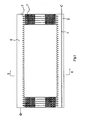
Fig. 1 is a schematic view of a heat exchanger according to an embodiment of the present invention; -
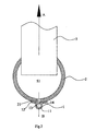
Fig. 2 is a partially cross-sectional view of the heat exchanger taken along line E-E inFig. 1 ; -
Figs. 3a and 3b show different types of the distribution opening in the distribution tube of the heat exchanger; -
Fig. 4 is a partially cross-sectional view of a heat exchanger according to another embodiment of the present invention; -
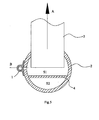
Fig. 5 is a partially cross-sectional view of a heat exchanger according to still another embodiment of the present invention; -
Fig. 6 is a partially cross-sectional view of a heat exchanger according to still further another embodiment of the present invention; and -
Fig. 7 is a partially cross-sectional view of a conventional heat exchanger. - Reference will be made in detail to embodiments of the present invention. The embodiments described herein with reference to drawings are explanatory, illustrative, and used to generally understand the present invention. The embodiments shall not be construed to limit the present invention. The same or similar elements and the elements having same or similar functions are denoted by like reference numerals throughout the descriptions.
- In the description, relative terms such as "longitudinal" as well as derivative thereof (e.g., "longitudinally", etc.) should be construed to refer to the orientation as then described or as shown in the drawings under discussion. These relative terms are for convenience of description and do not require that the present invention be constructed or operated in a particular orientation. Terms concerning "connected" and "communicated", refer to a relationship wherein structures are secured or attached to one another either directly or indirectly through intervening structures, as well as both movable or rigid attachments or relationships, unless expressly described otherwise.
- The heat exchanger according to an embodiment of the present invention will be described in detail with reference to the drawings below.
- As shown in
Fig. 1 , the heat exchanger according to an embodiment of the present invention comprises aninlet header 2, an outlet header 6,tubes 3, fins 7 and adistribution tube 1. - As shown in
Fig. 2 , theinlet header 2 defines a refrigerant chamber S1 therein. Of course, in the examples shown inFigs. 2 and4 , the whole inner chamber of theinlet header 2 is the refrigerant chamber S1. Alternatively, as shown inFigs. 5 and6 , a partition is disposed inside the inlet header so as to divide an interior of the inlet header into the refrigerant chamber S1 and a cavity S2 isolated from each other (which will be described below). - The outlet header 6 and the
inlet header 2 are spaced apart from each other, and for example, disposed substantially parallelly to each other. Two ends of each tube are connected and communicated with the inlet andoutlet headers 2, and 6 respectively, for example by welding, such that theinlet header 2 is communicated with the outlet header 6 via refrigerant channels intubes 3. The refrigerant channel oftube 3 may be a micro-channel for instance, therefore the heat exchanger is referred to as a micro-channel heat exchanger. Of course, the present invention is not limited to this. Each fin is disposed between adjacent tubes so as to enhance the effect of heat transfer. - As shown in
Figs. 1-2 andFigs. 3a-3b , adistribution opening 14 is formed in thedistribution tube 1. As shown inFig. 1 , thedistribution tube 1 is disposed outside the refrigerant chamber S1, and aninner chamber 13 of thedistribution tube 1 is communicated with the refrigerant chamber S1 via thedistribution opening 14. Of course, a throughhole 21 is formed accordingly in a wall of theinlet header 2 defining the refrigerant chamber S1. - With the heat exchanger according to some embodiments of the present invention, the
distribution tube 1 is not disposed in the refrigerant chamber S1 of theinlet header 2. In other words, thedistribution tube 1 is not inserted into the refrigerant within theinlet header 2. Therefore, assembling and disassembling of thedistribution tube 1 are simple, thedistribution tube 1 is easy to maintain, and the refrigerants in theinlet header 2 and thedistribution tube 1 do not affect disadvantageously each other, thus enhancing distribution of the refrigerant. - As shown in
Fig. 1 , in an embodiment of the present invention, thedistribution tube 1 is mounted onto the outer wall of theinlet header 2 and thedistribution opening 14 corresponds to the throughhole 21. Therefore, the refrigerant, which enters into theinner chamber 13 of thedistribution tube 1 from a refrigerant source (not shown), is sprayed into the refrigerant chamber S1 via thedistribution opening 14 and the throughhole 21, thus eliminating the separation of vapor refrigerant and liquid refrigerant in theinlet header 2 and enhancing the effect of heat transfer. In order to further enhance distribution of the refrigerant, a ratio of an inner diameter of thedistribution tube 1 to a hydraulic inner diameter of the refrigerant chamber S1 is within a range of about 0.17 - about 0.79. - In order to enhance the convenience of mounting, in an embodiment of the present invention, the
distribution tube 1 is formed integrally with a mountingfoot 12 having a surface adapted to outer surface ofinlet header 2, so that thedistribution tube 1 is fixed onto the outer wall of theinlet header 2, for example, by welding the mountingfoot 12 to the outer wall of theinlet header 2. In this case, thedistribution opening 14 is penetrated through the mountingfoot 12 and corresponded to the throughhole 21. - In an example of the present invention, as shown in
Fig. 3a , thedistribution opening 14 comprises a plurality of orifices formed in thedistribution tube 1 separated from each other. The orifice may be a circular orifice or a slot having any other shapes. Alternatively, as shown inFig. 3b , thedistribution opening 14 may be formed as a single slot extending along the longitudinal direction of thedistribution tube 1. Thedistribution opening 14 is circular and its hydraulic diameter is within a range of from about 0.2 to about 4 mm, thus further improving the heat transfer effect. Alternatively, a ratio of an area of thedistribution opening 14 to a cross sectional area of the refrigerant chamber S1 is within the range of from about 0.3 to about 2. Experiments conducted by the present inventors prove that the above range can enhance distribution of the refrigerant. - In some embodiments of the present invention, since the
distribution tube 1 is fixed onto the outer wall of theinlet header 2, the number of thedistribution tube 1 is easy to change. For example, the number of theinlet header 2 may be several so as to satisfy the requirements of the heat exchanger for different amount of refrigerant, and the distribution of the refrigerant is easy to control by controllingindividual distribution tubes 1. - In some embodiments of the present invention, an opposite direction B to an outflow direction of the refrigerant discharged from the
distribution opening 14 is at an angle of about 45 °- about 315 ° with a flow direction A of a refrigerant in thetubes 3. The distributing effect of the refrigerant is further enhanced by setting the angle between the direction A and B in the above angle range. For example, as shown inFig. 2 , the direction B is at an angle of 180°with the direction A. Alternatively, in an example of the present invention shown inFig. 5 , the direction B is at an angle of 90°with the direction A. - As shown in
Fig. 4 , in some examples of the present invention, thedistribution tube 1 without the mountingfoot 12 thereon is connected and communicated with the refrigerant chamber S1 of theinlet header 2 via acommunication pipe 5 rather than the mountingfoot 12. A first end of thecommunication pipe 5 is welded to thedistribution tube 1 at the position of thedistribution tube 14, and a second end thereof is extended into the refrigerant chamber S1 penetrated through the wall of theinlet header 2. Of course, the joint of thecommunication pipe 5 and theinlet header 2 is sealed, for example, via welding thecommunication pipe 5 to theinlet header 2, that is, the gap between thecommunication pipe 5 and theinlet header 2 is sealed. - The heat exchanger according to another embodiment of the invention will be described below. As shown in
Fig. 5 , apartition 4 is disposed inside theinlet header 2 so as to divide the interior of theinlet header 2 into the refrigerant chamber S1 and a cavity S2 isolated from each other. There will be no refrigerants in the cavity S2, and thedistribution tube 1 is fixed onto the outer wall of theinlet header 2 and communicated with the refrigerant chamber S1 via thedistribution opening 14 and the throughhole 21. The provision of thepartition 4 reduces the volume of the refrigerant chamber S1, thus further enhancing distribution of the refrigerant. - In the embodiment shown in
Fig. 5 , thedistribution tube 1 is formed with the mounting foot, so that thedistribution tube 1 may be fixed conveniently onto the outer wall of theinlet header 2 . -
Fig. 6 shows an alternative embodiment of the present invention. In the embodiment shown inFig. 6 , thedistribution tube 1 is disposed inside the cavity S2 rather than fixed onto the outer wall of theinlet header 2 and communicated with the refrigerant chamber S1 via thecommunication pipe 5. Therefore, thedistribution tube 1 is easy to assemble and disassemble, and is not affected by the refrigerant in theinlet header 2. Meanwhile, the volume of the refrigerant chamber S1 is reduced, thus improving the distributing effect of the refrigerant and improving the aesthetics of the heat exchanger. - The operation of the heat exchanger according to an example of the present invention will be described below.
- As shown in
Fig. 1 , the refrigerant enters into thedistribution tube 1 along the direction C, and then sprays into the refrigerant chamber S1 of theinlet header 2 via thedistribution opening 14, thus eliminating the separation of vapor refrigerant and liquid refrigerant in the two-phase flow, and finally the refrigerant flows towards the outlet header 6 along thetubes 3 and exchanges heat during this period. The refrigerant subject to heat exchanging enters into the outlet header 6 and is finally discharged from the outlet header 6 along the direction D. - Since the
distribution tube 1 is not inserted into the refrigerant within theinlet header 2, the refrigerant in theinlet header 2 and thedistribution tube 1 will not disturb disadvantageously each other, and thedistribution tube 1 is easy to assemble, disassemble and maintain. Meanwhile, thedistribution tube 1 may be disposed in plural, such that the heat exchanger can satisfy different requirements for the amount of the refrigerant by controllingindividual distribution tubes 1. - Reference throughout this specification to "an embodiment," "some embodiments," "one embodiment", "an example," or "some examples," means that a particular feature, structure, material, or characteristic described in connection with the embodiment or example is included in at least one embodiment or example of the invention. Thus, the appearances of the phrases such as "in some embodiments," "in one embodiment" "in an embodiment", "an example," or "some examples," in various places throughout this specification are not necessarily referring to the same embodiment or example of the invention. Furthermore, the particular features, structures, materials, or characteristics may be combined in any suitable manner in one or more embodiments or examples.
- Although explanatory embodiments have been shown and described, it would be appreciated by those skilled in the art that changes, alternatives, and modifications can be made in the embodiments without departing from spirit and principles of the invention. Such changes, alternatives, and modifications all fall into the scope of the claims and their equivalents.
Claims (13)
- A heat exchanger, comprising:an inlet header defining a refrigerant chamber therein;an outlet header spaced apart from the inlet header;a plurality of tubes, two ends of each tube being connected and communicated with the inlet and outlet headers respectively;a plurality of fins, each of which is interposed between adjacent tubes, anda distribution tube disposed outside the refrigerant chamber and formed with a distribution opening, through which the distribution tube is communicated with the refrigerant chamber.
- The heat exchanger according to claim 1, wherein the distribution tube is mounted onto an outer wall of the inlet header.
- The heat exchanger according to claim 2, wherein the distribution tube is formed integrally with a mounting foot, through which the distribution tube is mounted onto the outer wall of the inlet header.
- The heat exchanger according to claim 1, wherein a ratio of an inner diameter of the distribution tube to a hydraulic inner diameter of the refrigerant chamber is within a range of about 0.17 - about 0.79.
- The heat exchanger according to claim 1, wherein a partition is disposed inside the inlet header so as to divide an interior of the inlet header into the refrigerant chamber and a cavity isolated from each other.
- The heat exchanger according to claim 5, wherein the distribution tube is disposed inside the cavity.
- The heat exchanger according to any one of claims 1-6, further comprising a communication pipe, a first end of which is connected to the distribution tube so as to communicate with the distribution tube via the distribution opening and a second end thereof is communicated with the refrigerant chamber.
- The heat exchanger according to claim 1, wherein the distribution opening comprises a plurality of orifices formed in the distribution tube and separated from each other.
- The heat exchanger according to claim 1, wherein the distribution opening comprises a single slot formed in the distribution tube.
- The heat exchanger according to claim 1, wherein the distribution opening is circular and a hydraulic diameter thereof is within a range of about 0.2- about 4 mm.
- The heat exchanger according to claim 1, wherein a ratio of an area of the distribution opening to a cross sectional area of the refrigerant chamber is within a range of about 0.3- about 2.
- The heat exchanger according to claim 1, wherein a plurality of distribution tubes are disposed.
- The heat exchanger according to claim 1, wherein a flow direction of a refrigerant in the tubes is at an angle of about 45 °- about 315 °with an opposite direction to an outflow direction of the refrigerant discharged from the distribution opening.
Applications Claiming Priority (1)
| Application Number | Priority Date | Filing Date | Title |
|---|---|---|---|
| CN2009101734340A CN101660870B (en) | 2009-09-16 | 2009-09-16 | Heat exchanger capable of improving distribution performance of refrigerant |
Publications (3)
| Publication Number | Publication Date |
|---|---|
| EP2299224A2 true EP2299224A2 (en) | 2011-03-23 |
| EP2299224A3 EP2299224A3 (en) | 2014-09-03 |
| EP2299224B1 EP2299224B1 (en) | 2020-05-20 |
Family
ID=41789025
Family Applications (1)
| Application Number | Title | Priority Date | Filing Date |
|---|---|---|---|
| EP10009474.7A Active EP2299224B1 (en) | 2009-09-16 | 2010-09-13 | Heat exchanger with headers and distribution tube |
Country Status (3)
| Country | Link |
|---|---|
| US (1) | US20110061844A1 (en) |
| EP (1) | EP2299224B1 (en) |
| CN (1) | CN101660870B (en) |
Cited By (1)
| Publication number | Priority date | Publication date | Assignee | Title |
|---|---|---|---|---|
| EP2711658A3 (en) * | 2012-09-25 | 2014-09-10 | Behr GmbH & Co. KG | Heat exchanger |
Families Citing this family (13)
| Publication number | Priority date | Publication date | Assignee | Title |
|---|---|---|---|---|
| CN101865574B (en) | 2010-06-21 | 2013-01-30 | 三花控股集团有限公司 | Heat exchanger |
| CN101886891B (en) * | 2010-07-20 | 2012-07-18 | 三花丹佛斯(杭州)微通道换热器有限公司 | Refrigerant guiding device and heat exchanger with same |
| CN102564204B (en) * | 2010-12-08 | 2016-04-06 | 杭州三花微通道换热器有限公司 | Refrigerant distributing device and the heat exchanger with it |
| ES2602307T3 (en) * | 2013-01-24 | 2017-02-20 | Alcoil Usa Llc | Heat exchanger |
| ES2729602T3 (en) | 2013-01-28 | 2019-11-05 | Carrier Corp | Heat exchange unit with several tube banks with a manifold assembly |
| CN103148729B (en) * | 2013-03-19 | 2015-01-21 | 丹佛斯微通道换热器(嘉兴)有限公司 | Collecting pipe and heat exchanger with same |
| CN103389005B (en) | 2013-08-06 | 2015-08-05 | 杭州三花微通道换热器有限公司 | Refrigerant distributing device and the heat exchanger with it |
| US10337799B2 (en) | 2013-11-25 | 2019-07-02 | Carrier Corporation | Dual duty microchannel heat exchanger |
| US11585609B2 (en) * | 2014-05-06 | 2023-02-21 | Sanhua (Hangzhou) Micro Channel Heat Exchanger Co., Ltd. | Bent heat exchanger |
| US10907903B2 (en) | 2016-01-21 | 2021-02-02 | Samsung Electronics Co., Ltd. | Air conditioner with flow direction changing mechanism |
| CN105783085A (en) * | 2016-03-18 | 2016-07-20 | 广州市锦铝业科技有限公司 | Multifunctional wall body |
| CN114608352A (en) * | 2020-12-08 | 2022-06-10 | 杭州三花微通道换热器有限公司 | Heat exchanger |
| CN115342560B (en) * | 2022-06-27 | 2023-07-18 | 西安交通大学 | A flow uniform distribution device and its application |
Family Cites Families (13)
| Publication number | Priority date | Publication date | Assignee | Title |
|---|---|---|---|---|
| JP3017272B2 (en) * | 1990-11-07 | 2000-03-06 | 株式会社ゼクセル | Heat exchanger |
| JPH10206081A (en) * | 1997-01-27 | 1998-08-07 | Kobe Steel Ltd | Heat exchange panel for open rack type evaporator |
| JP2000346568A (en) * | 1999-05-31 | 2000-12-15 | Mitsubishi Heavy Ind Ltd | Heat exchanger |
| DE10149507A1 (en) * | 2001-10-06 | 2003-04-10 | Behr Gmbh & Co | Heat exchanger, in particular flat-tube heat exchanger of a motor vehicle |
| DE50212972D1 (en) * | 2001-12-21 | 2008-12-11 | Behr Gmbh & Co Kg | HEAT TRANSMITTER, ESPECIALLY FOR A MOTOR VEHICLE |
| JP3960233B2 (en) * | 2002-04-03 | 2007-08-15 | 株式会社デンソー | Heat exchanger |
| CN1536316A (en) * | 2003-04-11 | 2004-10-13 | 乐金电子(天津)电器有限公司 | Uniformly-distributing device of refrigerant for heat exchanger |
| JP4221244B2 (en) * | 2003-05-14 | 2009-02-12 | カルソニックカンセイ株式会社 | Combined heat exchanger |
| CN1611907A (en) * | 2003-10-30 | 2005-05-04 | 乐金电子(天津)电器有限公司 | Collector refrigerant distributing structure |
| US20080023184A1 (en) * | 2006-07-25 | 2008-01-31 | Henry Earl Beamer | Heat exchanger assembly |
| US8225853B2 (en) * | 2006-10-13 | 2012-07-24 | Carrier Corporation | Multi-pass heat exchangers having return manifolds with distributing inserts |
| EP2079974B1 (en) * | 2006-10-13 | 2012-03-14 | Carrier Corporation | Method and apparatus for improving distribution of fluid in a heat exchanger |
| US7921558B2 (en) * | 2008-01-09 | 2011-04-12 | Delphi Technologies, Inc. | Non-cylindrical refrigerant conduit and method of making same |
-
2009
- 2009-09-16 CN CN2009101734340A patent/CN101660870B/en active Active
-
2010
- 2010-08-31 US US12/872,508 patent/US20110061844A1/en not_active Abandoned
- 2010-09-13 EP EP10009474.7A patent/EP2299224B1/en active Active
Non-Patent Citations (1)
| Title |
|---|
| None |
Cited By (2)
| Publication number | Priority date | Publication date | Assignee | Title |
|---|---|---|---|---|
| EP2711658A3 (en) * | 2012-09-25 | 2014-09-10 | Behr GmbH & Co. KG | Heat exchanger |
| US9709338B2 (en) | 2012-09-25 | 2017-07-18 | Mahle International Gmbh | Heat exchanger |
Also Published As
| Publication number | Publication date |
|---|---|
| US20110061844A1 (en) | 2011-03-17 |
| CN101660870A (en) | 2010-03-03 |
| EP2299224B1 (en) | 2020-05-20 |
| EP2299224A3 (en) | 2014-09-03 |
| CN101660870B (en) | 2012-07-18 |
Similar Documents
| Publication | Publication Date | Title |
|---|---|---|
| EP2299224B1 (en) | Heat exchanger with headers and distribution tube | |
| US10852075B2 (en) | Refrigerant distributor of micro-channel heat exchanger | |
| EP2082181B1 (en) | Parallel flow heat exchanger | |
| US8176750B2 (en) | Heat exchanger | |
| US20130192808A1 (en) | Refrigerant guiding pipe and heat exchanger having refrigerant guiding pipe | |
| EP2977706B1 (en) | Manifold and heat exchanger having same | |
| EP2375209A2 (en) | Improved heat exchanger having an inlet distributor and outlet collector | |
| US20110000255A1 (en) | Microchannel heat exchanger with enhanced refrigerant distribution | |
| EP3120097B1 (en) | Microchannel heat exchanger evaporator | |
| EP3619492B1 (en) | Heat exchanger for heat pump applications | |
| WO2015027681A1 (en) | Refrigerant allocation component, collecting pipe assembly, and heat exchanger | |
| CN216668363U (en) | Microchannel heat exchanger and heat exchange system | |
| US12553674B2 (en) | Manifold assembly and heat exchanger | |
| US9702598B2 (en) | Evaporator | |
| US12031778B2 (en) | Plate-and-shell heat exchanger and a heat transfer plate for a plate-and-shell heat exchanger | |
| CN102297547B (en) | Heat exchanger | |
| KR101634399B1 (en) | A baffle of evaporator | |
| CN103389005A (en) | Refrigerant distribution device and heat exchanger provided with same | |
| CN113188355B (en) | Plate heat exchanger and heat exchange system with same | |
| CN116412695B (en) | Parallel flow heat exchanger and heat exchange system | |
| JP2017172906A (en) | Heat exchanger | |
| JP5508818B2 (en) | Evaporator | |
| JP2016183847A (en) | Heat exchanger | |
| KR20210141291A (en) | Distributor and air conditioner including the same | |
| CN116007244B (en) | Liquid separation structure and heat exchange assembly with same |
Legal Events
| Date | Code | Title | Description |
|---|---|---|---|
| PUAI | Public reference made under article 153(3) epc to a published international application that has entered the european phase |
Free format text: ORIGINAL CODE: 0009012 |
|
| AK | Designated contracting states |
Kind code of ref document: A2 Designated state(s): AL AT BE BG CH CY CZ DE DK EE ES FI FR GB GR HR HU IE IS IT LI LT LU LV MC MK MT NL NO PL PT RO SE SI SK SM TR |
|
| AX | Request for extension of the european patent |
Extension state: BA ME RS |
|
| RIN1 | Information on inventor provided before grant (corrected) |
Inventor name: JIANLONG, JIANG Inventor name: HUAZHAO, LIU Inventor name: HUANG, LIN-JIE Inventor name: FENG, WANG |
|
| RAP1 | Party data changed (applicant data changed or rights of an application transferred) |
Owner name: SANHUA HOLDING GROUP CO., LTD. Owner name: DANFOSS A/S |
|
| PUAL | Search report despatched |
Free format text: ORIGINAL CODE: 0009013 |
|
| AK | Designated contracting states |
Kind code of ref document: A3 Designated state(s): AL AT BE BG CH CY CZ DE DK EE ES FI FR GB GR HR HU IE IS IT LI LT LU LV MC MK MT NL NO PL PT RO SE SI SK SM TR |
|
| AX | Request for extension of the european patent |
Extension state: BA ME RS |
|
| RIC1 | Information provided on ipc code assigned before grant |
Ipc: F28D 1/053 20060101AFI20140730BHEP Ipc: F28F 9/02 20060101ALI20140730BHEP |
|
| 17P | Request for examination filed |
Effective date: 20150220 |
|
| RBV | Designated contracting states (corrected) |
Designated state(s): AL AT BE BG CH CY CZ DE DK EE ES FI FR GB GR HR HU IE IS IT LI LT LU LV MC MK MT NL NO PL PT RO SE SI SK SM TR |
|
| RAP1 | Party data changed (applicant data changed or rights of an application transferred) |
Owner name: DANFOSS A/S Owner name: SANHUA (HANGZHOU) MICRO CHANNEL HEAT EXCHANGER CO. |
|
| STAA | Information on the status of an ep patent application or granted ep patent |
Free format text: STATUS: EXAMINATION IS IN PROGRESS |
|
| 17Q | First examination report despatched |
Effective date: 20180327 |
|
| GRAP | Despatch of communication of intention to grant a patent |
Free format text: ORIGINAL CODE: EPIDOSNIGR1 |
|
| STAA | Information on the status of an ep patent application or granted ep patent |
Free format text: STATUS: GRANT OF PATENT IS INTENDED |
|
| INTG | Intention to grant announced |
Effective date: 20191217 |
|
| GRAS | Grant fee paid |
Free format text: ORIGINAL CODE: EPIDOSNIGR3 |
|
| GRAA | (expected) grant |
Free format text: ORIGINAL CODE: 0009210 |
|
| STAA | Information on the status of an ep patent application or granted ep patent |
Free format text: STATUS: THE PATENT HAS BEEN GRANTED |
|
| AK | Designated contracting states |
Kind code of ref document: B1 Designated state(s): AL AT BE BG CH CY CZ DE DK EE ES FI FR GB GR HR HU IE IS IT LI LT LU LV MC MK MT NL NO PL PT RO SE SI SK SM TR |
|
| REG | Reference to a national code |
Ref country code: GB Ref legal event code: FG4D |
|
| REG | Reference to a national code |
Ref country code: CH Ref legal event code: EP |
|
| REG | Reference to a national code |
Ref country code: DE Ref legal event code: R096 Ref document number: 602010064382 Country of ref document: DE |
|
| REG | Reference to a national code |
Ref country code: AT Ref legal event code: REF Ref document number: 1272874 Country of ref document: AT Kind code of ref document: T Effective date: 20200615 |
|
| REG | Reference to a national code |
Ref country code: LT Ref legal event code: MG4D |
|
| REG | Reference to a national code |
Ref country code: NL Ref legal event code: MP Effective date: 20200520 |
|
| PG25 | Lapsed in a contracting state [announced via postgrant information from national office to epo] |
Ref country code: SE Free format text: LAPSE BECAUSE OF FAILURE TO SUBMIT A TRANSLATION OF THE DESCRIPTION OR TO PAY THE FEE WITHIN THE PRESCRIBED TIME-LIMIT Effective date: 20200520 Ref country code: LT Free format text: LAPSE BECAUSE OF FAILURE TO SUBMIT A TRANSLATION OF THE DESCRIPTION OR TO PAY THE FEE WITHIN THE PRESCRIBED TIME-LIMIT Effective date: 20200520 Ref country code: IS Free format text: LAPSE BECAUSE OF FAILURE TO SUBMIT A TRANSLATION OF THE DESCRIPTION OR TO PAY THE FEE WITHIN THE PRESCRIBED TIME-LIMIT Effective date: 20200920 Ref country code: PT Free format text: LAPSE BECAUSE OF FAILURE TO SUBMIT A TRANSLATION OF THE DESCRIPTION OR TO PAY THE FEE WITHIN THE PRESCRIBED TIME-LIMIT Effective date: 20200921 Ref country code: FI Free format text: LAPSE BECAUSE OF FAILURE TO SUBMIT A TRANSLATION OF THE DESCRIPTION OR TO PAY THE FEE WITHIN THE PRESCRIBED TIME-LIMIT Effective date: 20200520 Ref country code: GR Free format text: LAPSE BECAUSE OF FAILURE TO SUBMIT A TRANSLATION OF THE DESCRIPTION OR TO PAY THE FEE WITHIN THE PRESCRIBED TIME-LIMIT Effective date: 20200821 Ref country code: NO Free format text: LAPSE BECAUSE OF FAILURE TO SUBMIT A TRANSLATION OF THE DESCRIPTION OR TO PAY THE FEE WITHIN THE PRESCRIBED TIME-LIMIT Effective date: 20200820 |
|
| PG25 | Lapsed in a contracting state [announced via postgrant information from national office to epo] |
Ref country code: BG Free format text: LAPSE BECAUSE OF FAILURE TO SUBMIT A TRANSLATION OF THE DESCRIPTION OR TO PAY THE FEE WITHIN THE PRESCRIBED TIME-LIMIT Effective date: 20200820 Ref country code: HR Free format text: LAPSE BECAUSE OF FAILURE TO SUBMIT A TRANSLATION OF THE DESCRIPTION OR TO PAY THE FEE WITHIN THE PRESCRIBED TIME-LIMIT Effective date: 20200520 Ref country code: LV Free format text: LAPSE BECAUSE OF FAILURE TO SUBMIT A TRANSLATION OF THE DESCRIPTION OR TO PAY THE FEE WITHIN THE PRESCRIBED TIME-LIMIT Effective date: 20200520 |
|
| REG | Reference to a national code |
Ref country code: AT Ref legal event code: MK05 Ref document number: 1272874 Country of ref document: AT Kind code of ref document: T Effective date: 20200520 |
|
| PG25 | Lapsed in a contracting state [announced via postgrant information from national office to epo] |
Ref country code: NL Free format text: LAPSE BECAUSE OF FAILURE TO SUBMIT A TRANSLATION OF THE DESCRIPTION OR TO PAY THE FEE WITHIN THE PRESCRIBED TIME-LIMIT Effective date: 20200520 Ref country code: AL Free format text: LAPSE BECAUSE OF FAILURE TO SUBMIT A TRANSLATION OF THE DESCRIPTION OR TO PAY THE FEE WITHIN THE PRESCRIBED TIME-LIMIT Effective date: 20200520 |
|
| PG25 | Lapsed in a contracting state [announced via postgrant information from national office to epo] |
Ref country code: RO Free format text: LAPSE BECAUSE OF FAILURE TO SUBMIT A TRANSLATION OF THE DESCRIPTION OR TO PAY THE FEE WITHIN THE PRESCRIBED TIME-LIMIT Effective date: 20200520 Ref country code: CZ Free format text: LAPSE BECAUSE OF FAILURE TO SUBMIT A TRANSLATION OF THE DESCRIPTION OR TO PAY THE FEE WITHIN THE PRESCRIBED TIME-LIMIT Effective date: 20200520 Ref country code: EE Free format text: LAPSE BECAUSE OF FAILURE TO SUBMIT A TRANSLATION OF THE DESCRIPTION OR TO PAY THE FEE WITHIN THE PRESCRIBED TIME-LIMIT Effective date: 20200520 Ref country code: SM Free format text: LAPSE BECAUSE OF FAILURE TO SUBMIT A TRANSLATION OF THE DESCRIPTION OR TO PAY THE FEE WITHIN THE PRESCRIBED TIME-LIMIT Effective date: 20200520 Ref country code: AT Free format text: LAPSE BECAUSE OF FAILURE TO SUBMIT A TRANSLATION OF THE DESCRIPTION OR TO PAY THE FEE WITHIN THE PRESCRIBED TIME-LIMIT Effective date: 20200520 Ref country code: ES Free format text: LAPSE BECAUSE OF FAILURE TO SUBMIT A TRANSLATION OF THE DESCRIPTION OR TO PAY THE FEE WITHIN THE PRESCRIBED TIME-LIMIT Effective date: 20200520 Ref country code: DK Free format text: LAPSE BECAUSE OF FAILURE TO SUBMIT A TRANSLATION OF THE DESCRIPTION OR TO PAY THE FEE WITHIN THE PRESCRIBED TIME-LIMIT Effective date: 20200520 |
|
| REG | Reference to a national code |
Ref country code: DE Ref legal event code: R097 Ref document number: 602010064382 Country of ref document: DE |
|
| PG25 | Lapsed in a contracting state [announced via postgrant information from national office to epo] |
Ref country code: PL Free format text: LAPSE BECAUSE OF FAILURE TO SUBMIT A TRANSLATION OF THE DESCRIPTION OR TO PAY THE FEE WITHIN THE PRESCRIBED TIME-LIMIT Effective date: 20200520 Ref country code: SK Free format text: LAPSE BECAUSE OF FAILURE TO SUBMIT A TRANSLATION OF THE DESCRIPTION OR TO PAY THE FEE WITHIN THE PRESCRIBED TIME-LIMIT Effective date: 20200520 |
|
| PLBE | No opposition filed within time limit |
Free format text: ORIGINAL CODE: 0009261 |
|
| STAA | Information on the status of an ep patent application or granted ep patent |
Free format text: STATUS: NO OPPOSITION FILED WITHIN TIME LIMIT |
|
| 26N | No opposition filed |
Effective date: 20210223 |
|
| PG25 | Lapsed in a contracting state [announced via postgrant information from national office to epo] |
Ref country code: MC Free format text: LAPSE BECAUSE OF FAILURE TO SUBMIT A TRANSLATION OF THE DESCRIPTION OR TO PAY THE FEE WITHIN THE PRESCRIBED TIME-LIMIT Effective date: 20200520 |
|
| REG | Reference to a national code |
Ref country code: CH Ref legal event code: PL |
|
| GBPC | Gb: european patent ceased through non-payment of renewal fee |
Effective date: 20200913 |
|
| PG25 | Lapsed in a contracting state [announced via postgrant information from national office to epo] |
Ref country code: SI Free format text: LAPSE BECAUSE OF FAILURE TO SUBMIT A TRANSLATION OF THE DESCRIPTION OR TO PAY THE FEE WITHIN THE PRESCRIBED TIME-LIMIT Effective date: 20200520 |
|
| REG | Reference to a national code |
Ref country code: BE Ref legal event code: MM Effective date: 20200930 |
|
| PG25 | Lapsed in a contracting state [announced via postgrant information from national office to epo] |
Ref country code: LU Free format text: LAPSE BECAUSE OF NON-PAYMENT OF DUE FEES Effective date: 20200913 |
|
| PG25 | Lapsed in a contracting state [announced via postgrant information from national office to epo] |
Ref country code: BE Free format text: LAPSE BECAUSE OF NON-PAYMENT OF DUE FEES Effective date: 20200930 Ref country code: CH Free format text: LAPSE BECAUSE OF NON-PAYMENT OF DUE FEES Effective date: 20200930 Ref country code: GB Free format text: LAPSE BECAUSE OF NON-PAYMENT OF DUE FEES Effective date: 20200913 Ref country code: IE Free format text: LAPSE BECAUSE OF NON-PAYMENT OF DUE FEES Effective date: 20200913 Ref country code: LI Free format text: LAPSE BECAUSE OF NON-PAYMENT OF DUE FEES Effective date: 20200930 |
|
| PG25 | Lapsed in a contracting state [announced via postgrant information from national office to epo] |
Ref country code: TR Free format text: LAPSE BECAUSE OF FAILURE TO SUBMIT A TRANSLATION OF THE DESCRIPTION OR TO PAY THE FEE WITHIN THE PRESCRIBED TIME-LIMIT Effective date: 20200520 Ref country code: MT Free format text: LAPSE BECAUSE OF FAILURE TO SUBMIT A TRANSLATION OF THE DESCRIPTION OR TO PAY THE FEE WITHIN THE PRESCRIBED TIME-LIMIT Effective date: 20200520 Ref country code: CY Free format text: LAPSE BECAUSE OF FAILURE TO SUBMIT A TRANSLATION OF THE DESCRIPTION OR TO PAY THE FEE WITHIN THE PRESCRIBED TIME-LIMIT Effective date: 20200520 |
|
| PG25 | Lapsed in a contracting state [announced via postgrant information from national office to epo] |
Ref country code: MK Free format text: LAPSE BECAUSE OF FAILURE TO SUBMIT A TRANSLATION OF THE DESCRIPTION OR TO PAY THE FEE WITHIN THE PRESCRIBED TIME-LIMIT Effective date: 20200520 |
|
| P01 | Opt-out of the competence of the unified patent court (upc) registered |
Effective date: 20230529 |
|
| REG | Reference to a national code |
Ref country code: DE Ref legal event code: R081 Ref document number: 602010064382 Country of ref document: DE Owner name: SANHUA (HANGZHOU) MICRO CHANNEL HEAT EXCHANGER, CN Free format text: FORMER OWNERS: DANFOSS A/S, NORDBORG, DK; SANHUA (HANGZHOU) MICRO CHANNEL HEAT EXCHANGER CO. LTD., HANGZHOU, ZHEJIANG, CN |
|
| PGFP | Annual fee paid to national office [announced via postgrant information from national office to epo] |
Ref country code: DE Payment date: 20250923 Year of fee payment: 16 |
|
| PGFP | Annual fee paid to national office [announced via postgrant information from national office to epo] |
Ref country code: FR Payment date: 20250924 Year of fee payment: 16 |
|
| PGFP | Annual fee paid to national office [announced via postgrant information from national office to epo] |
Ref country code: IT Payment date: 20250930 Year of fee payment: 16 |