EP2299121A2 - Integrated EGR mixer and ported shroud housing compressor - Google Patents
Integrated EGR mixer and ported shroud housing compressor Download PDFInfo
- Publication number
- EP2299121A2 EP2299121A2 EP10173138A EP10173138A EP2299121A2 EP 2299121 A2 EP2299121 A2 EP 2299121A2 EP 10173138 A EP10173138 A EP 10173138A EP 10173138 A EP10173138 A EP 10173138A EP 2299121 A2 EP2299121 A2 EP 2299121A2
- Authority
- EP
- European Patent Office
- Prior art keywords
- gas
- shroud
- compressor
- volute
- annular passage
- Prior art date
- Legal status (The legal status is an assumption and is not a legal conclusion. Google has not performed a legal analysis and makes no representation as to the accuracy of the status listed.)
- Withdrawn
Links
- 238000002485 combustion reaction Methods 0.000 claims description 12
- 210000002105 tongue Anatomy 0.000 claims description 10
- 230000007246 mechanism Effects 0.000 claims description 5
- 238000000034 method Methods 0.000 abstract description 8
- 239000007789 gas Substances 0.000 description 111
- 239000003570 air Substances 0.000 description 50
- 239000000203 mixture Substances 0.000 description 21
- 230000001174 ascending effect Effects 0.000 description 7
- 230000000694 effects Effects 0.000 description 3
- 239000000411 inducer Substances 0.000 description 3
- 239000007787 solid Substances 0.000 description 3
- 238000011144 upstream manufacturing Methods 0.000 description 2
- 230000001133 acceleration Effects 0.000 description 1
- 230000004075 alteration Effects 0.000 description 1
- 239000012080 ambient air Substances 0.000 description 1
- 239000000567 combustion gas Substances 0.000 description 1
- 238000010586 diagram Methods 0.000 description 1
- 230000009977 dual effect Effects 0.000 description 1
- 239000000446 fuel Substances 0.000 description 1
- 238000012986 modification Methods 0.000 description 1
- 230000004048 modification Effects 0.000 description 1
- 230000002265 prevention Effects 0.000 description 1
- 230000008707 rearrangement Effects 0.000 description 1
- 230000003134 recirculating effect Effects 0.000 description 1
- 238000006467 substitution reaction Methods 0.000 description 1
- 239000011800 void material Substances 0.000 description 1
Images




Classifications
-
- F—MECHANICAL ENGINEERING; LIGHTING; HEATING; WEAPONS; BLASTING
- F04—POSITIVE - DISPLACEMENT MACHINES FOR LIQUIDS; PUMPS FOR LIQUIDS OR ELASTIC FLUIDS
- F04D—NON-POSITIVE-DISPLACEMENT PUMPS
- F04D25/00—Pumping installations or systems
- F04D25/02—Units comprising pumps and their driving means
- F04D25/04—Units comprising pumps and their driving means the pump being fluid-driven
-
- F—MECHANICAL ENGINEERING; LIGHTING; HEATING; WEAPONS; BLASTING
- F02—COMBUSTION ENGINES; HOT-GAS OR COMBUSTION-PRODUCT ENGINE PLANTS
- F02M—SUPPLYING COMBUSTION ENGINES IN GENERAL WITH COMBUSTIBLE MIXTURES OR CONSTITUENTS THEREOF
- F02M26/00—Engine-pertinent apparatus for adding exhaust gases to combustion-air, main fuel or fuel-air mixture, e.g. by exhaust gas recirculation [EGR] systems
- F02M26/02—EGR systems specially adapted for supercharged engines
- F02M26/04—EGR systems specially adapted for supercharged engines with a single turbocharger
-
- F—MECHANICAL ENGINEERING; LIGHTING; HEATING; WEAPONS; BLASTING
- F02—COMBUSTION ENGINES; HOT-GAS OR COMBUSTION-PRODUCT ENGINE PLANTS
- F02M—SUPPLYING COMBUSTION ENGINES IN GENERAL WITH COMBUSTIBLE MIXTURES OR CONSTITUENTS THEREOF
- F02M26/00—Engine-pertinent apparatus for adding exhaust gases to combustion-air, main fuel or fuel-air mixture, e.g. by exhaust gas recirculation [EGR] systems
- F02M26/13—Arrangement or layout of EGR passages, e.g. in relation to specific engine parts or for incorporation of accessories
- F02M26/17—Arrangement or layout of EGR passages, e.g. in relation to specific engine parts or for incorporation of accessories in relation to the intake system
- F02M26/19—Means for improving the mixing of air and recirculated exhaust gases, e.g. venturis or multiple openings to the intake system
-
- F—MECHANICAL ENGINEERING; LIGHTING; HEATING; WEAPONS; BLASTING
- F02—COMBUSTION ENGINES; HOT-GAS OR COMBUSTION-PRODUCT ENGINE PLANTS
- F02M—SUPPLYING COMBUSTION ENGINES IN GENERAL WITH COMBUSTIBLE MIXTURES OR CONSTITUENTS THEREOF
- F02M26/00—Engine-pertinent apparatus for adding exhaust gases to combustion-air, main fuel or fuel-air mixture, e.g. by exhaust gas recirculation [EGR] systems
- F02M26/13—Arrangement or layout of EGR passages, e.g. in relation to specific engine parts or for incorporation of accessories
- F02M26/34—Arrangement or layout of EGR passages, e.g. in relation to specific engine parts or for incorporation of accessories with compressors, turbines or the like in the recirculation passage
-
- F—MECHANICAL ENGINEERING; LIGHTING; HEATING; WEAPONS; BLASTING
- F04—POSITIVE - DISPLACEMENT MACHINES FOR LIQUIDS; PUMPS FOR LIQUIDS OR ELASTIC FLUIDS
- F04D—NON-POSITIVE-DISPLACEMENT PUMPS
- F04D29/00—Details, component parts, or accessories
- F04D29/40—Casings; Connections of working fluid
- F04D29/42—Casings; Connections of working fluid for radial or helico-centrifugal pumps
- F04D29/4206—Casings; Connections of working fluid for radial or helico-centrifugal pumps especially adapted for elastic fluid pumps
- F04D29/4213—Casings; Connections of working fluid for radial or helico-centrifugal pumps especially adapted for elastic fluid pumps suction ports
-
- F—MECHANICAL ENGINEERING; LIGHTING; HEATING; WEAPONS; BLASTING
- F04—POSITIVE - DISPLACEMENT MACHINES FOR LIQUIDS; PUMPS FOR LIQUIDS OR ELASTIC FLUIDS
- F04D—NON-POSITIVE-DISPLACEMENT PUMPS
- F04D29/00—Details, component parts, or accessories
- F04D29/40—Casings; Connections of working fluid
- F04D29/42—Casings; Connections of working fluid for radial or helico-centrifugal pumps
- F04D29/44—Fluid-guiding means, e.g. diffusers
- F04D29/441—Fluid-guiding means, e.g. diffusers especially adapted for elastic fluid pumps
-
- F—MECHANICAL ENGINEERING; LIGHTING; HEATING; WEAPONS; BLASTING
- F02—COMBUSTION ENGINES; HOT-GAS OR COMBUSTION-PRODUCT ENGINE PLANTS
- F02B—INTERNAL-COMBUSTION PISTON ENGINES; COMBUSTION ENGINES IN GENERAL
- F02B37/00—Engines characterised by provision of pumps driven at least for part of the time by exhaust
-
- F—MECHANICAL ENGINEERING; LIGHTING; HEATING; WEAPONS; BLASTING
- F05—INDEXING SCHEMES RELATING TO ENGINES OR PUMPS IN VARIOUS SUBCLASSES OF CLASSES F01-F04
- F05B—INDEXING SCHEME RELATING TO WIND, SPRING, WEIGHT, INERTIA OR LIKE MOTORS, TO MACHINES OR ENGINES FOR LIQUIDS COVERED BY SUBCLASSES F03B, F03D AND F03G
- F05B2220/00—Application
- F05B2220/40—Application in turbochargers
-
- F—MECHANICAL ENGINEERING; LIGHTING; HEATING; WEAPONS; BLASTING
- F05—INDEXING SCHEMES RELATING TO ENGINES OR PUMPS IN VARIOUS SUBCLASSES OF CLASSES F01-F04
- F05D—INDEXING SCHEME FOR ASPECTS RELATING TO NON-POSITIVE-DISPLACEMENT MACHINES OR ENGINES, GAS-TURBINES OR JET-PROPULSION PLANTS
- F05D2250/00—Geometry
- F05D2250/50—Inlet or outlet
- F05D2250/51—Inlet
-
- Y—GENERAL TAGGING OF NEW TECHNOLOGICAL DEVELOPMENTS; GENERAL TAGGING OF CROSS-SECTIONAL TECHNOLOGIES SPANNING OVER SEVERAL SECTIONS OF THE IPC; TECHNICAL SUBJECTS COVERED BY FORMER USPC CROSS-REFERENCE ART COLLECTIONS [XRACs] AND DIGESTS
- Y02—TECHNOLOGIES OR APPLICATIONS FOR MITIGATION OR ADAPTATION AGAINST CLIMATE CHANGE
- Y02T—CLIMATE CHANGE MITIGATION TECHNOLOGIES RELATED TO TRANSPORTATION
- Y02T10/00—Road transport of goods or passengers
- Y02T10/10—Internal combustion engine [ICE] based vehicles
- Y02T10/12—Improving ICE efficiencies
Definitions
- Subject matter disclosed herein relates generally to turbomachinery for internal combustion engines and, in particular, to equipment and techniques for recirculating exhaust gas.
- Exhaust gas recirculation is widely used to improve emissions of internal combustions engines. With respect to turbocharged internal combustion engines, use of EGR alters compressor operation. On a compressor map, EGR moves engine running lines toward or beyond compressor surge lines. Compressors working beyond the surge line are unstable and have increased risk of mechanical failure. Another concern with EGR is adequate mixing of exhaust gas and fresh air. Inadequate mixing of exhaust gas and air can diminish engine performance and decrease benefits of EGR.
- Various exemplary systems, devices and methods are described herein that can enhance EGR and compressor performance.
- Fig. 1 is a diagram of a turbocharger and an internal combustion engine.
- Fig. 2 is a perspective view of an exemplary compressor housing that includes a shrouded port and a passage for exhaust gas.
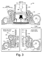
- Fig. 3 is a cross-sectional view of the compressor housing of Fig. 2 along a line labeled A-A.
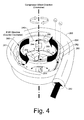
- Fig. 4 is a perspective view of flow space for the exhaust gas passage and the compressor wheel of Fig. 3 that indicates an intended direction of rotation of the wheel and a direction of swirl of the exhaust gas.
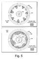
- Fig. 5 is a contour plot of circumferential or tangential velocity in a plane without EGR and a contour plot of circumferential or tangential velocity in the same plane with EGR, as provided by an exemplary compressor housing.
- Fig. 6 is a series plots of computational results for EGR delivery via an exemplary compressor housing and another arrangement for EGR delivery via a conventional compressor housing.
- Fig. 7 is a series of perspective views of various exhaust passage configurations with respect to a scroll of a compressor housing.
- Fig. 8 is a table of computational results for the various configurations of Fig. 7 .
- a conventional system 100 includes an internal combustion engine 110 and a turbocharger 120.
- the internal combustion engine 110 includes an engine block 118 housing one or more combustion chambers that operatively drive a shaft 112.
- an intake port 114 provides a flow path for air to the engine block 118 while an exhaust port 116 provides a flow path for exhaust from the engine block 118.
- the turbocharger 120 acts to extract energy from the exhaust and to provide energy to intake air, which may be combined with fuel to form combustion gas.
- the turbocharger 120 includes an air inlet 134, a shaft 122, a compressor 124, a turbine 126, a housing 128 and an exhaust outlet 136.
- the housing 128 may be referred to as a center housing as it is disposed between the compressor 124 and the turbine 126.
- the shaft 122 may be a shaft assembly that includes a variety of components.
- variable geometry unit and variable geometry controller optionally includes a variable geometry unit and a variable geometry controller.
- the variable geometry unit and variable geometry controller optionally include features such as those associated with commercially available variable geometry turbochargers (VGTs).
- VGTs include, for example, the GARRETT® VNTTM and AVNTTM turbochargers, which use multiple adjustable vanes to control the flow of exhaust across a turbine.
- An exemplary turbocharger may employ wastegate technology as an alternative or in addition to variable geometry technology.
- Fig. 2 shows a perspective view of an exemplary compressor housing 200 that includes a compressed air volute portion 210 having an outlet 212, an air intake portion 230 having an air inlet 232 and a gas volute portion 260 having a gas inlet 262.
- a line A-A defines a plane where cross-sectional views of the housing 200 along this plane are shown in Fig. 3 .
- Fig. 3 shows cross-sectional views of the housing 200 of Fig. 2 with respect to a r, z coordinate system.
- An upper cross-sectional view shows various dimensions, including an outer wall radius, r o , an intermediate wall radius, r m , an inner wall radius, r i , an axial location of a gas inlet z in , an axial location of a port z p and an axial location of an opening or nozzle z out .
- the cross-sectional view also shows arrows that represent flow of intake air, exhaust gas and mixed air and exhaust gas after some initial time.
- intake air is assumed to enter at 298 K and 100 kPa
- exhaust gas is assumed to enter at 500 K and 0.03 kg/s. Given these values, per computational trials, the mixture of air and exhaust gas exits the housing 200 at a mass flow rate of about 0.15 to about 0.20 kg/s.
- exhaust gas at 500 K enters the EGR volute where, at an initial time, it mixes with the air (or a mix of gas and air at a later time) and then becomes compressed by the operation of the compressor wheel as the mixture passes through the compressor housing.
- the intake portion 230 includes an inlet defined by a lip 232.
- the intake portion 230 includes a substantially cylindrical wall 236 that extends axially downward from the lip 232 to an edge 238 to form an intake air space 234.
- the intake portion 230 continues at another edge 240, which defines, in part, a compressor wheel shroud.
- a substantially cylindrical wall 242 (e.g., an inner wall with a radius r i ) extends axially downward from the edge 240 to yet another edge 246.
- the wall 242 is supported by a connector 244 that extends radially outward to connect the shroud to the gas volute portion 260.
- the intake portion 230 continues at another edge 248.
- a shroud wall 250 extends from the edge 248 axially downward and radially outward to a junction 252, which joins the compressor wheel shroud with a substantially planar wall 220 of the compressed air volute portion 210.
- the wall 220 forms an annular duct with a backplate or other component for passage of gas (e.g., air, exhaust, mixed air and exhaust) to a volute space 214 of the volute portion 210.
- the gas volute portion 260 includes a substantially tubular wall 268 that defines a gas volute space 264.
- the tubular wall 268 has an oblong or bulbous cross-section (in a r,z-plane) that defines, along a lower axial portion or base, a substantially annular opening 272.
- the annular opening 272 leads to a passage having a substantially J- or U-shaped cross-section (in a r,z-plane).
- the passage is defined by a pair of walls that define a substantially annular, axially descending passage that leads to an approximately 180 degree turn portion that leads to another substantially annular, axially ascending portion.
- the pair of descending walls are labeled 276, 280 while after the turn, the pair of ascending walls are labeled 282 and 284.
- one wall has descending portion 276 and ascending portion 284 while the other wall has descending portion 280 and ascending portion 282.
- the ascending wall 282 is shown with a radius r o while the ascending wall 284 is shown with a radius r m .
- the walls 282 and 284 define a gas inlet to an ascending passage.
- the wall 284 ascends to an edge 286.
- another wall 292 e.g., disposed along r m ) extends axially upward to an edge 294 that defines in part the opening 296 (e.g., a nozzle with an axial position z out ).
- the wall 282 (e.g., with an outer radius r o ) extends axially upward to a curved ceiling that descends slightly to end at an edge 298, which defines in part the opening 296 (e.g., a nozzle with an axial position z out ).
- the intake portion 210 and the gas volute portion 260 have various corresponding features.
- the edge 286 corresponds with the edge 246, the edge 290 corresponds with the edge 244, the edge 294 corresponds with the edge 238 and the edge 298 corresponds with the edge 236.
- the foregoing edges define the openings 288 (e.g., a port) and 296 (e.g., a nozzle). Flow of air and gas, via the openings 288 and 296, are described below with respect to the arrows in the upper cross-sectional view of Fig. 3 .
- a large open arrow represents intake air flowing inward to the intake space 234 via the inlet 232 of the intake portion 230 due to suction created by rotation of a compressor wheel (not shown).
- Smaller solid, curved arrows represent gas flowing to the intake portion 230 via the gas volute portion 260.
- Large solid arrows represent a mixture of air and gas flowing to the compressed air/gas volute space 214.
- a circulation loop is established between the opening or port 288 and the opening or nozzle 296.
- gas from the gas volute portion 260 mixes with intake air drawn into the compressor housing 200 via the inlet 232. This mixture then flows axially upward to the opening 296.
- the mixture is introduced to intake air flowing into the compressor housing 200 via the inlet.
- a mixture of air and gas flows through the opening 288. This is referred to herein, with respect to flow, as a steady-state condition or a pseudo-steady-state condition.
- the exemplary housing 200 of Figs. 2 and 3 can operate as a mixer for exhaust gas recirculation (EGR).
- EGR exhaust gas recirculation
- the housing 200 is a mixer that relies, in part, on a ported shroud.
- EGR is widely used to improve emissions from internal combustion engines.
- EGR can push the engine running lines to the left and often beyond compressor surge lines on compressor maps (e.g., where compressor pressure ratio is plotted against corrected flow). Compressors working beyond the surge line are typically unstable and have increased risk of mechanical failure.
- EGR requires adequate mixing of exhaust gas and intake air (e.g., fresh or ambient air) to ensure that the EGR can achieve its intended purpose.
- EGR must be implemented in limited space.
- the exemplary housing 200 of Figs. 2 and 3 can enhance compressor operation during EGR in a manner that does not have a significant impact on limited space of a road vehicle.
- the gas volute portion 260 provides gas to a compressor wheel housed by the housing 200 where the gas has tangential velocity and momentum in a direction opposite the intended direction of rotation of the compressor wheel.
- the gas volute portion 260 acts to accelerates the gas and circumferentially and uniformly distributes it to a nozzle which has its throat (i.e., the opening 296) located at the entry region of the ported shroud.
- the ported shroud serves three purposes: (i) acceleration of gas for better mixing; (ii) generation of a low pressure region around the port entry, which helps to draw air from the compressor impeller to the port; and (iii) prevention of gas flowing directly into the impeller through the port entry.
- the swirl direction of the ported shroud flow (i.e., flow emerging from the ported shroud), can have a significant influence on the effectiveness of the ported shroud. Specifically, if the swirl is in the same direction as compressor wheel rotation, the effectiveness of the ported shroud will be reduced because of reduced inducer work input to the flow. This is a condition that exists for conventional ported shrouds that reduces inducer work input. As described herein, the gas volute portion 260 can be used to affect swirl in a ported shroud.
- the gas volute portion 260 can, depending on particular parameters (e.g., gas flow, dimensions, etc.), reduce swirl in the direction of rotation of a compressor wheel at a shroud nozzle (e.g., the opening 296) or even reverse the direction of swirl at a shroud nozzle (e.g., the opening 296).
- an exemplary compressor housing includes concentric walls (e.g., an inner wall, an intermediate wall and an outer wall) that define a substantially annular passage (e.g., between an outer wall and an intermediate wall) and a compressor wheel shroud (e.g., by an inner wall).
- the housing further includes a gas inlet to the annular passage, one or more ports to the annular passage and an outlet nozzle or nozzles for introduction of a gas or a mixture of gases (e.g., air and exhaust gas) to an inlet for a compressor wheel.
- an exemplary compressor housing uses energy of exhaust gas (e.g., pressure, mass flow, etc.) to generate a counter swirl.
- exhaust gas e.g., pressure, mass flow, etc.
- an exemplary compressor housing can achieve better mixing of gas and air (or gas and a mixture of air and gas) and improve compressor stability.
- gas volute and compressor volute i.e., a gas volute and compressor volute
- relative position of the volute tongues of the gas volute and the compressor volute can affect mixing.
- a particular exemplary configuration includes a 60mm PV ported shroud compressor housing with an integrated EGR mixer.
- Fig. 4 shows the flow space for the exemplary configuration of Fig. 3 .
- Concentric walls, including an intermediate wall 292, an outer wall 282 and a volute space wall 280 define boundaries for the flow space shown in Fig. 4 .
- the flow space includes a substantially annular passage 283 between the intermediate wall 292 and the outer wall 282.
- Connectors 244 are shown as void spaces that extend between the intermediate wall 292 and the outer wall 282 (noting that the inner wall 242 is not shown in Fig. 4 ).
- the 4 further includes a gas inlet 281 to the annular passage 283, one or more ports 288 to the annular passage 283 and an outlet nozzle 296 (or nozzles) for introduction of a gas or a mixture of gases (e.g., air and exhaust gas) to an inlet of a compressor wheel (e.g., defined in part by the edge 240).
- the gas inlet 281 is defined at least in part by the walls 282 and 284, as shown in Fig. 3 .
- Such walls may include dividers or supports, which may define multiple gas inlets to an annular passage.
- the gas volute 260 receives gas via a volute inlet 262. Due to pressure at the volute inlet 262 and/or reduced pressure at the inlet 281 to the annular passage 283, gas flows or is drawn through the volute where it acquires tangential velocity and momentum in a direction opposite an intended direction of rotation of a compressor wheel 204.
- the compressor wheel 204 drives air or a mixture of gas and air to the annular passage 283. Such a flow of air or a mixture of gas and air may further be due in part to a reduced pressure at the nozzle 296 caused by operation of the compressor wheel 204.
- the air or mixture of gas and air has tangential velocity and momentum in the same direction as the direction of rotation of the compressor wheel 204 (see small dashed arrows). Passing through the one or more ports 288, this gas or gas and air mixture encounters gas in the annular passage 483 with an opposite tangential velocity and momentum (see solid arrows). Accordingly, as indicated in Fig.
- the ports may be arranged in various manners.
- another port such as the port 288 of Figs. 3 and 4 may exist, along with appropriate supports or connectors (see, e.g., the radially extending connectors 244).
- multiple ports may exist where none of the ports extends 360 degrees about a compressor wheel shroud.
- one or more ports may extend 360 degrees about a shroud while one or more other ports have smaller spans.
- axial position multiple ports may exist at substantially the same axial position. Alternatively, one or more ports may be arranged at different axial positions.
- an exemplary method includes rotating a compressor wheel in a compressor housing where the compressor housing includes an annular passage that surrounds a ported shroud and where the rotation of the wheel draws air to an inducer portion of the compressor wheel; swirling exhaust gas in a direction opposite the direction of rotation of the compressor wheel; introducing the swirling exhaust gas to the annular passage; forcing air radially outward through one or more ports in the ported shroud to the annular passage; in the annular passage, mixing the swirling exhaust gas with the forced air; and introducing the mixed air and exhaust gas to the compressor wheel via a nozzle.
- Such a method can include drawing or forcing the exhaust gas through a gas volute to generate swirl. Depending on the various flow patterns, such a method can introduce via a nozzle a mixture with a swirl in a direction opposite the direction of rotation of the compressor wheel.
- Fig. 5 shows contour plots for computation trials of an exemplary ported shroud without exhaust gas recirculation 510 and with exhaust gas recirculation 530.
- the plots 510, 530 show the compressor wheel 204, an inner wall (e.g., the wall 242 of Fig. 3 ), the connectors 244, the intermediate wall 292 and the outer wall 282.
- the plot 510 demonstrates, that without EGR (i.e., no gas flow through the gas volute 260), only a few limited regions of exist with negative swirl (i.e., swirl in a direction opposite the direction of rotation of the compressor wheel 204).
- the plot 530 demonstrates, that with EGR, negative swirl is increased, especially in a region adjacent the inner wall 242 (e.g., along the compressor wheel shroud).
- an exemplary ported shroud and EGR volute arrangement can significantly alter flow pattern upstream of a compressor wheel.
- the compressor wheel 204 rotates clockwise while exhaust gas is introduced counter-clockwise. From the front view of the plots 510, 530, computational trials demonstrate that the circumferential velocity is altered significantly. As mentioned, this type of alteration in flow upstream a compressor wheel may improve performance and help to avoid surge.
- Fig. 6 shows a series of plots for different boundary conditions 610, 630 that compare performance of an exemplary ported shroud 614, 634 and another device 618, 638 for introducing exhaust gas to an inlet stream of a compressor.
- boundary conditions 610 gas mass flow of 0.03 kg/s
- data from computational trials in the plots 614, 618 demonstrate that the exemplary ported shroud has improved mass flow convergence and hence better flow stability than the other device.
- the boundary conditions 630 gas mass flow of 0.02 kg/s
- data from computational trials in the plots 634, 638 demonstrate that the exemplary ported shroud has improved mass flow convergence and hence better flow stability than the other device.
- the computation trials demonstrate improved mixing and, for an increase in the gas flow rate (e.g., gas flow rate from 0.02 kg/s to 0.03 kg/s), the mixing effect becomes more prominent for the exemplary device compared to the other device.
- temperature uniformity was 0.998 and 0.951 while temperature deviation was 2.46 K and 2.44 K, for the exemplary device and the other device, respectively.
- temperature uniformity was 0.997 and 0.995 while temperature deviation was 3.80 K and 7.52 K, for the exemplary device and the other device, respectively (see Fig. 8 for definitions of uniformity and deviation).
- Fig. 7 shows various configurations for a tongue of a gas volute 760 and a tongue of a compressor volute 710. These examples include a 270 degree offset (example 731), a 180 degree offset (example 732), a 90 degree offset (example 733) and a 0 degree offset (example 734).
- Fig. 8 shows a table of results from computational trials for the examples 731, 732, 733 and 734 of Fig. 7 .
- the results demonstrate how offset between a gas volute 760 and a compressor volute 710 affects the performance of an exemplary compressor housing.
- the results demonstrate that the example 731, with a 270 degree offset, provided better mixing at higher mass flow (e.g., total mass of 0.18 kg/s) and better mixing at lower mass flow (e.g., total mass of 0.17kg/s).
- Equations are also provided in Fig. 8 for uniformity and deviation metrics. According to these metrics, a higher uniformity index predicts more uniform entropy or temperature while a higher deviation predicts less uniform entropy or temperature.
- the results of Fig. 8 show that tongue offset can have a significant effect on uniformity and deviation of temperature and entropy.
- a ported shroud for a compressor wheel includes concentric walls that define an annular passage and a compressor wheel shroud disposed about a central axis where a compressor wheel positioned with respect to the shroud has an intended direction of rotation about the central axis; positioned with respect to the central axis, from a lower axial position to a higher axial position, a gas inlet to the annular passage, one or more ports extending between the shroud and the annular passage and a nozzle; and a mechanism to provide, to the gas inlet to the annular passage, gas having swirl in a direction opposite the intended direction of rotation of the compressor wheel.
- the mechanism is a gas volute, however, other mechanisms may provide such a swirl (e.g. drawing or forcing exhaust gas through vanes, etc.).
- swirl can be characterized by tangential velocity and momentum (e.g., in a direction opposite the intended direction of rotation of a compressor wheel, in the same direction of rotation of a compressor wheel, clockwise, counter-clockwise, etc).
- a shroud may have a single port or multiple ports.
- a single port may extend partially or completely about a circumference of a shroud.
- one or more ports are disposed at one or more positions along an axial span defined by and to be coincident with a compressor wheel (e.g., along an axial span of a blade or blades).
- a nozzle may extend partially or completely about a circumference of a ported shroud.
- an exemplary compressor housing includes a compressor volute; concentric walls that define an annular passage and a compressor wheel shroud disposed about a central axis where a compressor wheel positioned with respect to the shroud has an intended direction of rotation about the central axis; positioned with respect to the central axis, from a lower axial position to a higher axial position, a gas inlet to the annular passage, one or more ports extending between the shroud and the annular passage and a nozzle; and a gas volute to provide, to the gas inlet to the annular passage, gas having swirl in a direction opposite the intended direction of rotation of the compressor wheel.
- Such a compressor housing may include a mount to mount the compressor housing to a center housing of a turbocharger (e.g., optionally including a backplate disposed between the compressor housing and the center housing).
- a compressor volute can include a tongue and a gas volute can include a tongue and where the tongues are offset.
- the offset may be an angle of approximately 270 degrees.
- a gas volute may be integral with a compressor housing (see, e.g., the housing 200 of Figs. 2 and 3 ).
Landscapes
- Engineering & Computer Science (AREA)
- Mechanical Engineering (AREA)
- General Engineering & Computer Science (AREA)
- Chemical & Material Sciences (AREA)
- Combustion & Propulsion (AREA)
- Structures Of Non-Positive Displacement Pumps (AREA)
- Supercharger (AREA)
Abstract
An exemplary compressor housing (200) includes a compressor volute (210); concentric walls (292,282,280) that define an annular passage (283) and a compressor wheel shroud (240) disposed about a central axis where a compressor wheel (204) positioned with respect to the shroud has an intended direction of rotation about the central axis; positioned with respect to the central axis, from a lower axial position to a higher axial position, a gas inlet (262) to the annular passage, one or more ports (288) extending between the shroud and the annular passage and a nozzle (296); and a gas volute (260) to provide, to the gas inlet to the annular passage, gas having swirl in a direction opposite the intended direction of rotation of the compressor wheel. Various other exemplary devices, systems, methods, etc., are also disclosed.
Description
- Subject matter disclosed herein relates generally to turbomachinery for internal combustion engines and, in particular, to equipment and techniques for recirculating exhaust gas.
- Exhaust gas recirculation (EGR) is widely used to improve emissions of internal combustions engines. With respect to turbocharged internal combustion engines, use of EGR alters compressor operation. On a compressor map, EGR moves engine running lines toward or beyond compressor surge lines. Compressors working beyond the surge line are unstable and have increased risk of mechanical failure. Another concern with EGR is adequate mixing of exhaust gas and fresh air. Inadequate mixing of exhaust gas and air can diminish engine performance and decrease benefits of EGR. Various exemplary systems, devices and methods are described herein that can enhance EGR and compressor performance.
- A more complete understanding of the various methods, devices, systems, arrangements, etc., described herein, and equivalents thereof, may be had by reference to the following detailed description when taken in conjunction with the accompanying drawings where:
-
Fig. 1 is a diagram of a turbocharger and an internal combustion engine. -
Fig. 2 is a perspective view of an exemplary compressor housing that includes a shrouded port and a passage for exhaust gas. -
Fig. 3 is a cross-sectional view of the compressor housing ofFig. 2 along a line labeled A-A. -
Fig. 4 is a perspective view of flow space for the exhaust gas passage and the compressor wheel ofFig. 3 that indicates an intended direction of rotation of the wheel and a direction of swirl of the exhaust gas. -
Fig. 5 is a contour plot of circumferential or tangential velocity in a plane without EGR and a contour plot of circumferential or tangential velocity in the same plane with EGR, as provided by an exemplary compressor housing. -
Fig. 6 is a series plots of computational results for EGR delivery via an exemplary compressor housing and another arrangement for EGR delivery via a conventional compressor housing. -
Fig. 7 is a series of perspective views of various exhaust passage configurations with respect to a scroll of a compressor housing. -
Fig. 8 is a table of computational results for the various configurations ofFig. 7 . - Turbochargers are frequently utilized to increase output of an internal combustion engine. Referring to
Fig. 1 , aconventional system 100 includes aninternal combustion engine 110 and aturbocharger 120. Theinternal combustion engine 110 includes an engine block 118 housing one or more combustion chambers that operatively drive ashaft 112. As shown inFig. 1 , anintake port 114 provides a flow path for air to the engine block 118 while anexhaust port 116 provides a flow path for exhaust from the engine block 118. - The
turbocharger 120 acts to extract energy from the exhaust and to provide energy to intake air, which may be combined with fuel to form combustion gas. As shown inFig. 1 , theturbocharger 120 includes anair inlet 134, ashaft 122, acompressor 124, aturbine 126, ahousing 128 and anexhaust outlet 136. Thehousing 128 may be referred to as a center housing as it is disposed between thecompressor 124 and theturbine 126. Theshaft 122 may be a shaft assembly that includes a variety of components. - Referring to the
turbine 126, such a turbine optionally includes a variable geometry unit and a variable geometry controller. The variable geometry unit and variable geometry controller optionally include features such as those associated with commercially available variable geometry turbochargers (VGTs). Commercially available VGTs include, for example, the GARRETT® VNT™ and AVNT™ turbochargers, which use multiple adjustable vanes to control the flow of exhaust across a turbine. An exemplary turbocharger may employ wastegate technology as an alternative or in addition to variable geometry technology. -
Fig. 2 shows a perspective view of anexemplary compressor housing 200 that includes a compressedair volute portion 210 having anoutlet 212, anair intake portion 230 having anair inlet 232 and agas volute portion 260 having agas inlet 262. A line A-A defines a plane where cross-sectional views of thehousing 200 along this plane are shown inFig. 3 . -
Fig. 3 shows cross-sectional views of thehousing 200 ofFig. 2 with respect to a r, z coordinate system. An upper cross-sectional view shows various dimensions, including an outer wall radius, ro, an intermediate wall radius, rm, an inner wall radius, ri, an axial location of a gas inlet zin, an axial location of a port zp and an axial location of an opening or nozzle zout. The cross-sectional view also shows arrows that represent flow of intake air, exhaust gas and mixed air and exhaust gas after some initial time. In this example, intake air is assumed to enter at 298 K and 100 kPa, exhaust gas is assumed to enter at 500 K and 0.03 kg/s. Given these values, per computational trials, the mixture of air and exhaust gas exits thehousing 200 at a mass flow rate of about 0.15 to about 0.20 kg/s. - The computational trials demonstrate that when an internal combustion engine is working at low power, compressor mass flow is quite small and surge may occur. With EGR, in computational trials, exhaust gas at 500 K (e.g., optionally cooled to achieve a desired temperature) enters the EGR volute where, at an initial time, it mixes with the air (or a mix of gas and air at a later time) and then becomes compressed by the operation of the compressor wheel as the mixture passes through the compressor housing.
- Before providing a description of flow in the
housing 200, various details of the housing are described with respect to reference numerals. In a lower right cross-sectional view, details of theintake portion 230 are labeled while in a lower left cross-sectional view, details of thegas volute portion 260 are labeled. - As shown in the lower right view, the
intake portion 230 includes an inlet defined by alip 232. Theintake portion 230 includes a substantiallycylindrical wall 236 that extends axially downward from thelip 232 to anedge 238 to form anintake air space 234. After an axial gap that defines an opening 296 (e.g., a nozzle with an axial position zout), theintake portion 230 continues at anotheredge 240, which defines, in part, a compressor wheel shroud. A substantially cylindrical wall 242 (e.g., an inner wall with a radius ri) extends axially downward from theedge 240 to yet anotheredge 246. As shown in the example ofFig. 3 , thewall 242 is supported by aconnector 244 that extends radially outward to connect the shroud to thegas volute portion 260. - After another axial gap that defines another opening 288 (e.g., a port with an axial position zp), the
intake portion 230 continues at anotheredge 248. Ashroud wall 250 extends from theedge 248 axially downward and radially outward to ajunction 252, which joins the compressor wheel shroud with a substantiallyplanar wall 220 of the compressedair volute portion 210. Specifically, thewall 220 forms an annular duct with a backplate or other component for passage of gas (e.g., air, exhaust, mixed air and exhaust) to avolute space 214 of thevolute portion 210. - As shown in the lower left view, the
gas volute portion 260 includes a substantiallytubular wall 268 that defines agas volute space 264. Thetubular wall 268 has an oblong or bulbous cross-section (in a r,z-plane) that defines, along a lower axial portion or base, a substantiallyannular opening 272. Theannular opening 272 leads to a passage having a substantially J- or U-shaped cross-section (in a r,z-plane). In the example ofFig. 3 , the passage is defined by a pair of walls that define a substantially annular, axially descending passage that leads to an approximately 180 degree turn portion that leads to another substantially annular, axially ascending portion. To facilitate description, the pair of descending walls are labeled 276, 280 while after the turn, the pair of ascending walls are labeled 282 and 284. In other words, one wall has descendingportion 276 and ascendingportion 284 while the other wall has descendingportion 280 and ascendingportion 282. With reference to the upper cross-sectional view, theascending wall 282 is shown with a radius ro while theascending wall 284 is shown with a radius rm. At an axial position zin, thewalls - In the example of
Fig. 3 , along a so-called intermediate radius (e.g., rm), thewall 284 ascends to anedge 286. After a gap, commencing at anedge 290 that defines in part the opening 288 (e.g., a port with an axial position zp), another wall 292 (e.g., disposed along rm) extends axially upward to anedge 294 that defines in part the opening 296 (e.g., a nozzle with an axial position zout). In the example ofFig. 3 , the wall 282 (e.g., with an outer radius ro) extends axially upward to a curved ceiling that descends slightly to end at anedge 298, which defines in part the opening 296 (e.g., a nozzle with an axial position zout). - As shown in
Fig. 3 , theintake portion 210 and thegas volute portion 260 have various corresponding features. Specifically, theedge 286 corresponds with theedge 246, theedge 290 corresponds with theedge 244, theedge 294 corresponds with theedge 238 and theedge 298 corresponds with theedge 236. Further, the foregoing edges define the openings 288 (e.g., a port) and 296 (e.g., a nozzle). Flow of air and gas, via theopenings Fig. 3 . - In
Fig. 3 , a large open arrow represents intake air flowing inward to theintake space 234 via theinlet 232 of theintake portion 230 due to suction created by rotation of a compressor wheel (not shown). Smaller solid, curved arrows represent gas flowing to theintake portion 230 via thegas volute portion 260. Large solid arrows represent a mixture of air and gas flowing to the compressed air/gas volute space 214. - As indicated by the arrows, a circulation loop is established between the opening or
port 288 and the opening ornozzle 296. At an initial starting point in time, at theopening 288, gas from thegas volute portion 260 mixes with intake air drawn into thecompressor housing 200 via theinlet 232. This mixture then flows axially upward to theopening 296. At theopening 296, the mixture is introduced to intake air flowing into thecompressor housing 200 via the inlet. Thus, very shortly after the initial time, a mixture of air and gas flows through theopening 288. This is referred to herein, with respect to flow, as a steady-state condition or a pseudo-steady-state condition. - The
exemplary housing 200 ofFigs. 2 and3 can operate as a mixer for exhaust gas recirculation (EGR). In such a configuration, thehousing 200 is a mixer that relies, in part, on a ported shroud. EGR is widely used to improve emissions from internal combustion engines. However, EGR can push the engine running lines to the left and often beyond compressor surge lines on compressor maps (e.g., where compressor pressure ratio is plotted against corrected flow). Compressors working beyond the surge line are typically unstable and have increased risk of mechanical failure. Further, EGR requires adequate mixing of exhaust gas and intake air (e.g., fresh or ambient air) to ensure that the EGR can achieve its intended purpose. Yet further, for road vehicles, EGR must be implemented in limited space. As described herein, theexemplary housing 200 ofFigs. 2 and3 can enhance compressor operation during EGR in a manner that does not have a significant impact on limited space of a road vehicle. - In the example of
Figs. 2 and3 , thegas volute portion 260 provides gas to a compressor wheel housed by thehousing 200 where the gas has tangential velocity and momentum in a direction opposite the intended direction of rotation of the compressor wheel. Thegas volute portion 260 acts to accelerates the gas and circumferentially and uniformly distributes it to a nozzle which has its throat (i.e., the opening 296) located at the entry region of the ported shroud. In such a configuration, the ported shroud serves three purposes: (i) acceleration of gas for better mixing; (ii) generation of a low pressure region around the port entry, which helps to draw air from the compressor impeller to the port; and (iii) prevention of gas flowing directly into the impeller through the port entry. - In the configuration of
Figs. 2 and3 , air (or a mixture of air and gas) drawn radially outward via the opening or port 288 (i.e., to the annular passage) will have a strong swirl (i.e., tangential velocity) in the same direction of rotation as the compressor wheel. On the other hand, gas entering the annular passage associated with thegas volute portion 260 will have a strong swirl in the opposite direction of compressor wheel rotation. Hence, mixing of gas from thegas volute portion 260 and air (or a mixture of air and gas) flowing radially outward via theopening 288 is enhanced due to the effects of counter-swirl. - Referring now to the opening or
nozzle 296, the swirl direction of the ported shroud flow (i.e., flow emerging from the ported shroud), can have a significant influence on the effectiveness of the ported shroud. Specifically, if the swirl is in the same direction as compressor wheel rotation, the effectiveness of the ported shroud will be reduced because of reduced inducer work input to the flow. This is a condition that exists for conventional ported shrouds that reduces inducer work input. As described herein, thegas volute portion 260 can be used to affect swirl in a ported shroud. Specifically, thegas volute portion 260 can, depending on particular parameters (e.g., gas flow, dimensions, etc.), reduce swirl in the direction of rotation of a compressor wheel at a shroud nozzle (e.g., the opening 296) or even reverse the direction of swirl at a shroud nozzle (e.g., the opening 296). - As described herein, along a radial dimension, an exemplary compressor housing includes concentric walls (e.g., an inner wall, an intermediate wall and an outer wall) that define a substantially annular passage (e.g., between an outer wall and an intermediate wall) and a compressor wheel shroud (e.g., by an inner wall). The housing further includes a gas inlet to the annular passage, one or more ports to the annular passage and an outlet nozzle or nozzles for introduction of a gas or a mixture of gases (e.g., air and exhaust gas) to an inlet for a compressor wheel.
- As described herein, an exemplary compressor housing uses energy of exhaust gas (e.g., pressure, mass flow, etc.) to generate a counter swirl. By mixing such counter swirling exhaust gas with air (or a mixture of air and exhaust gas) from a shroud port, swirl of the final mixture introduced to a compressor wheel is reduced and can even be reversed. Accordingly, together with the suction function provided by a shroud nozzle, introduction of counter-swirling gas improves effectiveness of a ported shroud.
- As described herein, an exemplary compressor housing can achieve better mixing of gas and air (or gas and a mixture of air and gas) and improve compressor stability. For examples that include a dual volute approach (i.e., a gas volute and compressor volute), as described in more detail below, relative position of the volute tongues of the gas volute and the compressor volute can affect mixing. A particular exemplary configuration includes a 60mm PV ported shroud compressor housing with an integrated EGR mixer.
-
Fig. 4 shows the flow space for the exemplary configuration ofFig. 3 . Concentric walls, including anintermediate wall 292, anouter wall 282 and avolute space wall 280 define boundaries for the flow space shown inFig. 4 . The flow space includes a substantiallyannular passage 283 between theintermediate wall 292 and theouter wall 282.Connectors 244 are shown as void spaces that extend between theintermediate wall 292 and the outer wall 282 (noting that theinner wall 242 is not shown inFig. 4 ). The configuration ofFig. 4 further includes agas inlet 281 to theannular passage 283, one ormore ports 288 to theannular passage 283 and an outlet nozzle 296 (or nozzles) for introduction of a gas or a mixture of gases (e.g., air and exhaust gas) to an inlet of a compressor wheel (e.g., defined in part by the edge 240). Thegas inlet 281 is defined at least in part by thewalls Fig. 3 . Such walls may include dividers or supports, which may define multiple gas inlets to an annular passage. - In the example of
Fig. 4 , thegas volute 260 receives gas via avolute inlet 262. Due to pressure at thevolute inlet 262 and/or reduced pressure at theinlet 281 to theannular passage 283, gas flows or is drawn through the volute where it acquires tangential velocity and momentum in a direction opposite an intended direction of rotation of acompressor wheel 204. - At the one or
more ports 288, thecompressor wheel 204 drives air or a mixture of gas and air to theannular passage 283. Such a flow of air or a mixture of gas and air may further be due in part to a reduced pressure at thenozzle 296 caused by operation of thecompressor wheel 204. At the one ormore ports 288, the air or mixture of gas and air has tangential velocity and momentum in the same direction as the direction of rotation of the compressor wheel 204 (see small dashed arrows). Passing through the one ormore ports 288, this gas or gas and air mixture encounters gas in the annular passage 483 with an opposite tangential velocity and momentum (see solid arrows). Accordingly, as indicated inFig. 4 , vigorous mixing occurs, which can alter the swirl of the gas or gas and air mixture entering via the one ormore ports 288. Depending on the operational conditions, the size and shape of the one ormore ports 288, gas pressure at thevolute inlet 262, dimensions of thegas volute 260, etc., the mixture of gas and air exiting theannular passage 283 at thenozzle 296 has a reduced swirl or a swirl opposite the direction of rotation of thecompressor wheel 204. - In a configuration with multiple ports, the ports may be arranged in various manners. For example, another port such as the
port 288 ofFigs. 3 and4 may exist, along with appropriate supports or connectors (see, e.g., the radially extending connectors 244). In another example, multiple ports may exist where none of the ports extends 360 degrees about a compressor wheel shroud. In yet another example, one or more ports may extend 360 degrees about a shroud while one or more other ports have smaller spans. With respect to axial position, multiple ports may exist at substantially the same axial position. Alternatively, one or more ports may be arranged at different axial positions. - As described herein, an exemplary method includes rotating a compressor wheel in a compressor housing where the compressor housing includes an annular passage that surrounds a ported shroud and where the rotation of the wheel draws air to an inducer portion of the compressor wheel; swirling exhaust gas in a direction opposite the direction of rotation of the compressor wheel; introducing the swirling exhaust gas to the annular passage; forcing air radially outward through one or more ports in the ported shroud to the annular passage; in the annular passage, mixing the swirling exhaust gas with the forced air; and introducing the mixed air and exhaust gas to the compressor wheel via a nozzle. Such a method can include drawing or forcing the exhaust gas through a gas volute to generate swirl. Depending on the various flow patterns, such a method can introduce via a nozzle a mixture with a swirl in a direction opposite the direction of rotation of the compressor wheel.
-
Fig. 5 shows contour plots for computation trials of an exemplary ported shroud withoutexhaust gas recirculation 510 and withexhaust gas recirculation 530. With reference to the example ofFig. 4 , theplots compressor wheel 204, an inner wall (e.g., thewall 242 ofFig. 3 ), theconnectors 244, theintermediate wall 292 and theouter wall 282. - The
plot 510 demonstrates, that without EGR (i.e., no gas flow through the gas volute 260), only a few limited regions of exist with negative swirl (i.e., swirl in a direction opposite the direction of rotation of the compressor wheel 204). In contrast, theplot 530 demonstrates, that with EGR, negative swirl is increased, especially in a region adjacent the inner wall 242 (e.g., along the compressor wheel shroud). - As described herein, an exemplary ported shroud and EGR volute arrangement can significantly alter flow pattern upstream of a compressor wheel. As shown in the example of
Fig. 5 , thecompressor wheel 204 rotates clockwise while exhaust gas is introduced counter-clockwise. From the front view of theplots -
Fig. 6 shows a series of plots fordifferent boundary conditions ported shroud device plots plots - Further, the computation trials demonstrate improved mixing and, for an increase in the gas flow rate (e.g., gas flow rate from 0.02 kg/s to 0.03 kg/s), the mixing effect becomes more prominent for the exemplary device compared to the other device. At 0.02 kg/s, temperature uniformity was 0.998 and 0.951 while temperature deviation was 2.46 K and 2.44 K, for the exemplary device and the other device, respectively. At 0.03 kg/s, temperature uniformity was 0.997 and 0.995 while temperature deviation was 3.80 K and 7.52 K, for the exemplary device and the other device, respectively (see
Fig. 8 for definitions of uniformity and deviation). -
Fig. 7 shows various configurations for a tongue of agas volute 760 and a tongue of acompressor volute 710. These examples include a 270 degree offset (example 731), a 180 degree offset (example 732), a 90 degree offset (example 733) and a 0 degree offset (example 734). -
Fig. 8 shows a table of results from computational trials for the examples 731, 732, 733 and 734 ofFig. 7 . The results demonstrate how offset between agas volute 760 and acompressor volute 710 affects the performance of an exemplary compressor housing. Specifically, the results demonstrate that the example 731, with a 270 degree offset, provided better mixing at higher mass flow (e.g., total mass of 0.18 kg/s) and better mixing at lower mass flow (e.g., total mass of 0.17kg/s). Equations are also provided inFig. 8 for uniformity and deviation metrics. According to these metrics, a higher uniformity index predicts more uniform entropy or temperature while a higher deviation predicts less uniform entropy or temperature. The results ofFig. 8 show that tongue offset can have a significant effect on uniformity and deviation of temperature and entropy. - As described herein, a ported shroud for a compressor wheel includes concentric walls that define an annular passage and a compressor wheel shroud disposed about a central axis where a compressor wheel positioned with respect to the shroud has an intended direction of rotation about the central axis; positioned with respect to the central axis, from a lower axial position to a higher axial position, a gas inlet to the annular passage, one or more ports extending between the shroud and the annular passage and a nozzle; and a mechanism to provide, to the gas inlet to the annular passage, gas having swirl in a direction opposite the intended direction of rotation of the compressor wheel. In various examples, the mechanism is a gas volute, however, other mechanisms may provide such a swirl (e.g. drawing or forcing exhaust gas through vanes, etc.). As described herein, swirl can be characterized by tangential velocity and momentum (e.g., in a direction opposite the intended direction of rotation of a compressor wheel, in the same direction of rotation of a compressor wheel, clockwise, counter-clockwise, etc).
- As described herein, a shroud may have a single port or multiple ports. A single port may extend partially or completely about a circumference of a shroud. In general, one or more ports are disposed at one or more positions along an axial span defined by and to be coincident with a compressor wheel (e.g., along an axial span of a blade or blades). Similarly, a nozzle may extend partially or completely about a circumference of a ported shroud.
- As described herein, an exemplary compressor housing includes a compressor volute; concentric walls that define an annular passage and a compressor wheel shroud disposed about a central axis where a compressor wheel positioned with respect to the shroud has an intended direction of rotation about the central axis; positioned with respect to the central axis, from a lower axial position to a higher axial position, a gas inlet to the annular passage, one or more ports extending between the shroud and the annular passage and a nozzle; and a gas volute to provide, to the gas inlet to the annular passage, gas having swirl in a direction opposite the intended direction of rotation of the compressor wheel. Such a compressor housing may include a mount to mount the compressor housing to a center housing of a turbocharger (e.g., optionally including a backplate disposed between the compressor housing and the center housing). As described with respect to
Fig. 7 , a compressor volute can include a tongue and a gas volute can include a tongue and where the tongues are offset. For example, the offset may be an angle of approximately 270 degrees. As shown in various examples, a gas volute may be integral with a compressor housing (see, e.g., thehousing 200 ofFigs. 2 and3 ). - Although some exemplary methods, devices, systems, arrangements, etc., have been illustrated in the accompanying Drawings and described in the foregoing Detailed Description, it will be understood that the exemplary embodiments disclosed are not limiting, but are capable of numerous rearrangements, modifications and substitutions without departing from the spirit set forth and defined by the following claims.
Claims (17)
- A ported shroud for a compressor wheel comprising:concentric walls that define an annular passage and a compressor wheel shroud disposed about a central axis wherein a compressor wheel positioned with respect to the shroud has an intended direction of rotation about the central axis;positioned with respect to the central axis, from a lower axial position to a higher axial position, a gas inlet to the annular passage, one or more ports extending between the shroud and the annular passage and a nozzle; anda mechanism to provide, to the gas inlet to the annular passage, gas having swirl in a direction opposite the intended direction of rotation of the compressor wheel.
- The ported shroud of claim 1 wherein the mechanism comprises a gas volute.
- The ported shroud of claim 2 wherein the gas volute comprises a volute inlet to receive gas and wherein the gas volute imparts swirl to the gas as it flows from the volute inlet through the gas volute and to the gas inlet to the annular passage.
- The ported shroud of claim 1 wherein the swirl comprises tangential velocity and momentum in a direction opposite the intended direction of rotation of the compressor wheel.
- The ported shroud of claim 1 wherein the gas comprises exhaust gas from an internal combustion engine.
- The ported shroud of claim 1 comprising a single port.
- The ported shroud of claim 1 comprising multiple ports.
- The ported shroud of claim 1 wherein the one or more ports are disposed at one or more positions along an axial span defined by and to be coincident with a compressor wheel.
- The ported shroud of claim 1 wherein the nozzle extends circumferentially about the ported shroud.
- A compressor housing comprising:a compressor volute;concentric walls that define an annular passage and a compressor wheel shroud disposed about a central axis wherein a compressor wheel positioned with respect to the shroud has an intended direction of rotation about the central axis;positioned with respect to the central axis, from a lower axial position to a higher axial position, a gas inlet to the annular passage, one or more ports extending between the shroud and the annular passage and a nozzle; anda gas volute to provide, to the gas inlet to the annular passage, gas having swirl in a direction opposite the intended direction of rotation of the compressor wheel.
- The compressor housing of claim 10 wherein the compressor volute comprises a tongue and wherein the gas volute comprises a tongue and wherein the tongues comprise an offset.
- The compressor housing of claim 11 wherein the offset comprises an angle of approximately 270 degrees.
- The compressor housing of claim 10 further comprising a mount to mount the compressor housing to a center housing of a turbocharger.
- The compressor housing of claim 10 wherein the gas comprises exhaust gas from an internal combustion engine.
- The compressor housing of claim 10 wherein the shroud comprises multiple ports.
- The compressor housing of claim 10 wherein the one or more ports are disposed at one or more positions along an axial span defined by and to be coincident with a compressor wheel housed by the compressor housing.
- The compressor housing of claim 10 wherein the nozzle extends circumferentially about the shroud.
Applications Claiming Priority (1)
| Application Number | Priority Date | Filing Date | Title |
|---|---|---|---|
| US12/553,787 US9091275B2 (en) | 2009-09-03 | 2009-09-03 | Integrated EGR mixer and ported shroud housing compressor |
Publications (1)
| Publication Number | Publication Date |
|---|---|
| EP2299121A2 true EP2299121A2 (en) | 2011-03-23 |
Family
ID=43087137
Family Applications (1)
| Application Number | Title | Priority Date | Filing Date |
|---|---|---|---|
| EP10173138A Withdrawn EP2299121A2 (en) | 2009-09-03 | 2010-08-17 | Integrated EGR mixer and ported shroud housing compressor |
Country Status (2)
| Country | Link |
|---|---|
| US (1) | US9091275B2 (en) |
| EP (1) | EP2299121A2 (en) |
Cited By (7)
| Publication number | Priority date | Publication date | Assignee | Title |
|---|---|---|---|---|
| EP2501439A4 (en) * | 2009-11-19 | 2014-11-05 | Resmed Motor Technologies Inc | BLOWER |
| EP2960528A4 (en) * | 2013-02-22 | 2016-01-20 | Mitsubishi Heavy Ind Ltd | CENTRIFUGAL COMPRESSOR |
| EP2987983A4 (en) * | 2013-04-16 | 2016-04-27 | Toyota Motor Co Ltd | COMPRESSOR FOR EXHAUST GAS TURBOCHARGER |
| GB2535996A (en) * | 2015-02-27 | 2016-09-07 | Ford Global Tech Llc | A low condensation LP EGR System |
| WO2019199962A1 (en) * | 2018-04-10 | 2019-10-17 | Carrier Corporation | Compressor having extended range and stability |
| WO2020152143A1 (en) * | 2019-01-21 | 2020-07-30 | Volkswagen Ag | Assembly for an air supply of an internal combustion engine, and air supply section for an internal combustion engine with an assembly of this type |
| US11761407B1 (en) | 2022-12-08 | 2023-09-19 | General Electric Company | Inlet mixer for exhaust gas recirculation in power generation systems |
Families Citing this family (21)
| Publication number | Priority date | Publication date | Assignee | Title |
|---|---|---|---|---|
| GB0821089D0 (en) * | 2008-11-19 | 2008-12-24 | Ford Global Tech Llc | A method for improving the performance of a radial compressor |
| US9759228B2 (en) * | 2009-10-16 | 2017-09-12 | GM Global Technology Operations LLC | Turbocharger and air induction system incorporating the same and method of using the same |
| US9567942B1 (en) * | 2010-12-02 | 2017-02-14 | Concepts Nrec, Llc | Centrifugal turbomachines having extended performance ranges |
| US9217396B2 (en) * | 2010-12-22 | 2015-12-22 | GM Global Technology Operations LLC | Boosting devices with integral features for recirculating exhaust gas |
| WO2012087907A2 (en) * | 2010-12-22 | 2012-06-28 | Honeywell International, Inc. | Turbocharger and engine cylinder head assembly |
| US9133793B2 (en) | 2010-12-22 | 2015-09-15 | GM Global Technology Operations LLC | Boosting devices with integral features for recirculating exhaust gas |
| JP6024211B2 (en) * | 2012-05-30 | 2016-11-09 | いすゞ自動車株式会社 | Internal combustion engine and control method thereof |
| CN104781519B (en) * | 2012-11-28 | 2017-06-23 | 博格华纳公司 | The compressor stage of the vortex supercharger with flow amplifier |
| US9303650B2 (en) | 2013-06-24 | 2016-04-05 | Ford Global Technologies, Llc | Introduction of exhaust gas recirculation at a compressor blade trailing edge |
| CN108291504A (en) * | 2015-08-25 | 2018-07-17 | 博格华纳公司 | Mixing device and methods of making and using same |
| US9926891B2 (en) | 2015-11-18 | 2018-03-27 | General Electric Company | System and method of exhaust gas recirculation |
| WO2017194079A1 (en) * | 2016-05-09 | 2017-11-16 | Volvo Truck Corporation | An inlet system for an internal combustion engine |
| US9951793B2 (en) | 2016-06-01 | 2018-04-24 | Borgwarner Inc. | Ported shroud geometry to reduce blade-pass noise |
| US10100785B2 (en) | 2016-06-30 | 2018-10-16 | Borgwarner Inc. | Compressor stage EGR injection |
| JP6294406B2 (en) * | 2016-08-04 | 2018-03-14 | 本田技研工業株式会社 | Compressor housing |
| US10436211B2 (en) | 2016-08-15 | 2019-10-08 | Borgwarner Inc. | Compressor wheel, method of making the same, and turbocharger including the same |
| CN107083994B (en) | 2017-06-16 | 2023-03-24 | 传孚科技(厦门)有限公司 | Air pressure engine |
| US20200025157A1 (en) * | 2018-07-17 | 2020-01-23 | GM Global Technology Operations LLC | Exhaust gas recirculation system and method of operating the same |
| US11408362B2 (en) * | 2018-08-28 | 2022-08-09 | Borgwarner Inc. | High efficiency turbocharger with EGR system |
| FR3111666B1 (en) * | 2020-06-17 | 2022-08-05 | Safran Helicopter Engines | RECOVERED CYCLE AIRCRAFT TURBOMACHINE |
| US11591991B1 (en) | 2021-08-27 | 2023-02-28 | Ford Global Technologies, Llc | Methods and systems for merging EGR with intake air |
Family Cites Families (20)
| Publication number | Priority date | Publication date | Assignee | Title |
|---|---|---|---|---|
| BE791867A (en) * | 1971-11-26 | 1973-05-24 | Wallace Murray Corp | DUAL COLLECTOR TURBOCHARGER COMPRESSOR |
| US4969805A (en) * | 1989-05-02 | 1990-11-13 | Allied-Signal Inc. | Unidirectional turbocharger assembly |
| US6520738B2 (en) * | 2001-03-15 | 2003-02-18 | Honeywell International, Inc. | Plenum entry bulk swirl generator |
| DE10158874A1 (en) * | 2001-11-30 | 2003-06-12 | Daimler Chrysler Ag | Exhaust gas turbocharger for an internal combustion engine and method for operating a supercharged internal combustion engine |
| AU2002368156A1 (en) * | 2002-08-13 | 2004-02-25 | Honeywell International, Inc. | Compressor |
| US6651431B1 (en) * | 2002-08-28 | 2003-11-25 | Ford Global Technologies, Llc | Boosted internal combustion engines and air compressors used therein |
| US7775759B2 (en) * | 2003-12-24 | 2010-08-17 | Honeywell International Inc. | Centrifugal compressor with surge control, and associated method |
| DE602004014541D1 (en) * | 2004-06-07 | 2008-07-31 | Honeywell Int Inc | COMPRESSOR WITH DETACHABLE TRANSFER AND METHOD |
| DE602004015337D1 (en) * | 2004-06-07 | 2008-09-04 | Honeywell Int Inc | COMPRESSOR WITH RETURN AND METHOD |
| DE102004040893A1 (en) * | 2004-08-24 | 2006-03-02 | Bayerische Motoren Werke Ag | turbocharger |
| US20070144170A1 (en) * | 2005-12-22 | 2007-06-28 | Caterpillar Inc. | Compressor having integral EGR valve and mixer |
| US7475539B2 (en) * | 2006-05-24 | 2009-01-13 | Honeywell International, Inc. | Inclined rib ported shroud compressor housing |
| US7721542B2 (en) * | 2006-06-13 | 2010-05-25 | Honeywell International, Inc. | Exhaust gas recirculation mixer |
| US7874789B2 (en) * | 2007-04-06 | 2011-01-25 | Honeywell International, Inc. | Compressor and compressor housing |
| US8272832B2 (en) * | 2008-04-17 | 2012-09-25 | Honeywell International Inc. | Centrifugal compressor with surge control, and associated method |
| JP5451247B2 (en) * | 2008-09-10 | 2014-03-26 | ボーグワーナー インコーポレーテッド | Turbocharger connection for reverse rotation of passive pre-turn |
| US7926473B2 (en) * | 2008-09-12 | 2011-04-19 | Ford Global Technologies | Air supply system for an internal combustion engine |
| US8266906B2 (en) * | 2009-03-11 | 2012-09-18 | GM Global Technology Operations LLC | Asymmetric split-inlet turbine housing |
| US20110011084A1 (en) * | 2009-07-16 | 2011-01-20 | Denso Corporation | Exhaust gas recirculation system for internal combustion engine |
| GB2474344B (en) * | 2009-10-06 | 2016-01-27 | Cummins Ltd | Turbomachine |
-
2009
- 2009-09-03 US US12/553,787 patent/US9091275B2/en not_active Expired - Fee Related
-
2010
- 2010-08-17 EP EP10173138A patent/EP2299121A2/en not_active Withdrawn
Non-Patent Citations (1)
| Title |
|---|
| None |
Cited By (12)
| Publication number | Priority date | Publication date | Assignee | Title |
|---|---|---|---|---|
| EP2501439A4 (en) * | 2009-11-19 | 2014-11-05 | Resmed Motor Technologies Inc | BLOWER |
| US8973576B2 (en) | 2009-11-19 | 2015-03-10 | Resmed Motor Technologies Inc | Blower |
| US9662463B2 (en) | 2009-11-19 | 2017-05-30 | Resmed Motor Technologies Inc. | Blower |
| US10940280B2 (en) | 2009-11-19 | 2021-03-09 | Resmed Motor Technologies Inc. | Blower |
| EP2960528A4 (en) * | 2013-02-22 | 2016-01-20 | Mitsubishi Heavy Ind Ltd | CENTRIFUGAL COMPRESSOR |
| US10125793B2 (en) | 2013-02-22 | 2018-11-13 | Mitsubishi Heavy Industries, Ltd. | Centrifugal compressor |
| EP2987983A4 (en) * | 2013-04-16 | 2016-04-27 | Toyota Motor Co Ltd | COMPRESSOR FOR EXHAUST GAS TURBOCHARGER |
| GB2535996A (en) * | 2015-02-27 | 2016-09-07 | Ford Global Tech Llc | A low condensation LP EGR System |
| GB2535996B (en) * | 2015-02-27 | 2019-12-11 | Ford Global Tech Llc | A low condensation LP EGR System |
| WO2019199962A1 (en) * | 2018-04-10 | 2019-10-17 | Carrier Corporation | Compressor having extended range and stability |
| WO2020152143A1 (en) * | 2019-01-21 | 2020-07-30 | Volkswagen Ag | Assembly for an air supply of an internal combustion engine, and air supply section for an internal combustion engine with an assembly of this type |
| US11761407B1 (en) | 2022-12-08 | 2023-09-19 | General Electric Company | Inlet mixer for exhaust gas recirculation in power generation systems |
Also Published As
| Publication number | Publication date |
|---|---|
| US9091275B2 (en) | 2015-07-28 |
| US20110048003A1 (en) | 2011-03-03 |
Similar Documents
| Publication | Publication Date | Title |
|---|---|---|
| US9091275B2 (en) | Integrated EGR mixer and ported shroud housing compressor | |
| KR101696747B1 (en) | Compressor of an exhaust-gas turbocharger | |
| EP1853825B1 (en) | Turbocharger having compressor with ported second-stage shroud | |
| EP2975269B1 (en) | Centrifugal compressor | |
| CN103097692B (en) | Nozzled turbocharger turbine | |
| EP2960528B1 (en) | Centrifugal compressor | |
| KR101987201B1 (en) | Compressor cover for turbochargers | |
| US7575411B2 (en) | Engine intake air compressor having multiple inlets and method | |
| CN105229264B (en) | Turbine and the internal combustion engine with the turbine | |
| CN102434232B (en) | Turbine exhaust plenum | |
| EP2987983B1 (en) | Compressor for exhaust-gas turbo-supercharger | |
| RU2575837C2 (en) | Device and method for reduction in mass flow rate of air for combustion with decreased emission in expanded operating range for single-shaft gas turbine | |
| EP2963302B1 (en) | Parallel twin-impeller compressor having swirl-imparting device for one impeller | |
| US7305827B2 (en) | Inlet duct for rearward-facing compressor wheel, and turbocharger incorporating same | |
| JP2009047163A (en) | Internal combustion engine system having power turbine with broad efficiency range | |
| CN105339673A (en) | Centrifugal compressor with inlet duct having swirl generators | |
| CN114837759B (en) | Diffuser space for a turbine of a turbomachine | |
| US9567942B1 (en) | Centrifugal turbomachines having extended performance ranges | |
| JP2007292075A (en) | Optimization form of back-flow combustion system for gas turbine engine | |
| RU2628166C2 (en) | Method for operation of gas-turbine power plant with spent gas recycling and corresponding gas-turbine power plant | |
| US7553122B2 (en) | Self-aspirated flow control system for centrifugal compressors | |
| CN107542574A (en) | The pressure charging system of compressor and internal combustion engine | |
| CN105569742A (en) | Gas introducing device before gas turbine | |
| US10851705B1 (en) | Variable inlet guide vane system for a turbocharger used in a motor vehicle | |
| CN110735814B (en) | Centrifugal compressor with inclined diffuser |
Legal Events
| Date | Code | Title | Description |
|---|---|---|---|
| PUAI | Public reference made under article 153(3) epc to a published international application that has entered the european phase |
Free format text: ORIGINAL CODE: 0009012 |
|
| 17P | Request for examination filed |
Effective date: 20100817 |
|
| AK | Designated contracting states |
Kind code of ref document: A2 Designated state(s): AL AT BE BG CH CY CZ DE DK EE ES FI FR GB GR HR HU IE IS IT LI LT LU LV MC MK MT NL NO PL PT RO SE SI SK SM TR |
|
| AX | Request for extension of the european patent |
Extension state: BA ME RS |
|
| RAP1 | Party data changed (applicant data changed or rights of an application transferred) |
Owner name: HONEYWELL INTERNATIONAL INC. |
|
| STAA | Information on the status of an ep patent application or granted ep patent |
Free format text: STATUS: THE APPLICATION HAS BEEN WITHDRAWN |
|
| 18W | Application withdrawn |
Effective date: 20160113 |