EP2299055A1 - Automotive vacuum vane pump - Google Patents
Automotive vacuum vane pump Download PDFInfo
- Publication number
- EP2299055A1 EP2299055A1 EP09170219A EP09170219A EP2299055A1 EP 2299055 A1 EP2299055 A1 EP 2299055A1 EP 09170219 A EP09170219 A EP 09170219A EP 09170219 A EP09170219 A EP 09170219A EP 2299055 A1 EP2299055 A1 EP 2299055A1
- Authority
- EP
- European Patent Office
- Prior art keywords
- vane
- pump
- automotive vacuum
- metal
- vane pump
- Prior art date
- Legal status (The legal status is an assumption and is not a legal conclusion. Google has not performed a legal analysis and makes no representation as to the accuracy of the status listed.)
- Granted
Links
- 229910052751 metal Inorganic materials 0.000 claims description 19
- 239000002184 metal Substances 0.000 claims description 19
- 239000004033 plastic Substances 0.000 claims description 9
- 229920003023 plastic Polymers 0.000 claims description 9
- 229910000838 Al alloy Inorganic materials 0.000 claims description 4
- 229920001187 thermosetting polymer Polymers 0.000 claims description 4
- 229920002430 Fibre-reinforced plastic Polymers 0.000 claims 2
- 239000011151 fibre-reinforced plastic Substances 0.000 claims 2
- 229920000049 Carbon (fiber) Polymers 0.000 claims 1
- 239000004917 carbon fiber Substances 0.000 claims 1
- VNWKTOKETHGBQD-UHFFFAOYSA-N methane Chemical compound C VNWKTOKETHGBQD-UHFFFAOYSA-N 0.000 claims 1
- 238000005299 abrasion Methods 0.000 description 6
- 238000004519 manufacturing process Methods 0.000 description 3
- 239000000463 material Substances 0.000 description 3
- 239000000835 fiber Substances 0.000 description 2
- 239000013585 weight reducing agent Substances 0.000 description 2
- 235000001674 Agaricus brunnescens Nutrition 0.000 description 1
- 229910052782 aluminium Inorganic materials 0.000 description 1
- XAGFODPZIPBFFR-UHFFFAOYSA-N aluminium Chemical compound [Al] XAGFODPZIPBFFR-UHFFFAOYSA-N 0.000 description 1
- 238000005452 bending Methods 0.000 description 1
- 238000010276 construction Methods 0.000 description 1
- 238000009749 continuous casting Methods 0.000 description 1
- 230000007423 decrease Effects 0.000 description 1
- 238000005265 energy consumption Methods 0.000 description 1
- 229910001385 heavy metal Inorganic materials 0.000 description 1
- 239000003562 lightweight material Substances 0.000 description 1
- 238000000034 method Methods 0.000 description 1
- 238000000926 separation method Methods 0.000 description 1
Images


Classifications
-
- F—MECHANICAL ENGINEERING; LIGHTING; HEATING; WEAPONS; BLASTING
- F01—MACHINES OR ENGINES IN GENERAL; ENGINE PLANTS IN GENERAL; STEAM ENGINES
- F01C—ROTARY-PISTON OR OSCILLATING-PISTON MACHINES OR ENGINES
- F01C21/00—Component parts, details or accessories not provided for in groups F01C1/00 - F01C20/00
- F01C21/08—Rotary pistons
- F01C21/0809—Construction of vanes or vane holders
- F01C21/0881—Construction of vanes or vane holders the vanes consisting of two or more parts
-
- F—MECHANICAL ENGINEERING; LIGHTING; HEATING; WEAPONS; BLASTING
- F04—POSITIVE - DISPLACEMENT MACHINES FOR LIQUIDS; PUMPS FOR LIQUIDS OR ELASTIC FLUIDS
- F04C—ROTARY-PISTON, OR OSCILLATING-PISTON, POSITIVE-DISPLACEMENT MACHINES FOR LIQUIDS; ROTARY-PISTON, OR OSCILLATING-PISTON, POSITIVE-DISPLACEMENT PUMPS
- F04C18/00—Rotary-piston pumps specially adapted for elastic fluids
- F04C18/30—Rotary-piston pumps specially adapted for elastic fluids having the characteristics covered by two or more of groups F04C18/02, F04C18/08, F04C18/22, F04C18/24, F04C18/48, or having the characteristics covered by one of these groups together with some other type of movement between co-operating members
- F04C18/34—Rotary-piston pumps specially adapted for elastic fluids having the characteristics covered by two or more of groups F04C18/02, F04C18/08, F04C18/22, F04C18/24, F04C18/48, or having the characteristics covered by one of these groups together with some other type of movement between co-operating members having the movement defined in group F04C18/08 or F04C18/22 and relative reciprocation between the co-operating members
- F04C18/344—Rotary-piston pumps specially adapted for elastic fluids having the characteristics covered by two or more of groups F04C18/02, F04C18/08, F04C18/22, F04C18/24, F04C18/48, or having the characteristics covered by one of these groups together with some other type of movement between co-operating members having the movement defined in group F04C18/08 or F04C18/22 and relative reciprocation between the co-operating members with vanes reciprocating with respect to the inner member
- F04C18/3441—Rotary-piston pumps specially adapted for elastic fluids having the characteristics covered by two or more of groups F04C18/02, F04C18/08, F04C18/22, F04C18/24, F04C18/48, or having the characteristics covered by one of these groups together with some other type of movement between co-operating members having the movement defined in group F04C18/08 or F04C18/22 and relative reciprocation between the co-operating members with vanes reciprocating with respect to the inner member the inner and outer member being in contact along one line or continuous surface substantially parallel to the axis of rotation
- F04C18/3442—Rotary-piston pumps specially adapted for elastic fluids having the characteristics covered by two or more of groups F04C18/02, F04C18/08, F04C18/22, F04C18/24, F04C18/48, or having the characteristics covered by one of these groups together with some other type of movement between co-operating members having the movement defined in group F04C18/08 or F04C18/22 and relative reciprocation between the co-operating members with vanes reciprocating with respect to the inner member the inner and outer member being in contact along one line or continuous surface substantially parallel to the axis of rotation the surfaces of the inner and outer member, forming the inlet and outlet opening
-
- F—MECHANICAL ENGINEERING; LIGHTING; HEATING; WEAPONS; BLASTING
- F04—POSITIVE - DISPLACEMENT MACHINES FOR LIQUIDS; PUMPS FOR LIQUIDS OR ELASTIC FLUIDS
- F04C—ROTARY-PISTON, OR OSCILLATING-PISTON, POSITIVE-DISPLACEMENT MACHINES FOR LIQUIDS; ROTARY-PISTON, OR OSCILLATING-PISTON, POSITIVE-DISPLACEMENT PUMPS
- F04C2220/00—Application
- F04C2220/10—Vacuum
-
- F—MECHANICAL ENGINEERING; LIGHTING; HEATING; WEAPONS; BLASTING
- F05—INDEXING SCHEMES RELATING TO ENGINES OR PUMPS IN VARIOUS SUBCLASSES OF CLASSES F01-F04
- F05C—INDEXING SCHEME RELATING TO MATERIALS, MATERIAL PROPERTIES OR MATERIAL CHARACTERISTICS FOR MACHINES, ENGINES OR PUMPS OTHER THAN NON-POSITIVE-DISPLACEMENT MACHINES OR ENGINES
- F05C2201/00—Metals
- F05C2201/90—Alloys not otherwise provided for
- F05C2201/903—Aluminium alloy, e.g. AlCuMgPb F34,37
-
- F—MECHANICAL ENGINEERING; LIGHTING; HEATING; WEAPONS; BLASTING
- F05—INDEXING SCHEMES RELATING TO ENGINES OR PUMPS IN VARIOUS SUBCLASSES OF CLASSES F01-F04
- F05C—INDEXING SCHEME RELATING TO MATERIALS, MATERIAL PROPERTIES OR MATERIAL CHARACTERISTICS FOR MACHINES, ENGINES OR PUMPS OTHER THAN NON-POSITIVE-DISPLACEMENT MACHINES OR ENGINES
- F05C2253/00—Other material characteristics; Treatment of material
- F05C2253/04—Composite, e.g. fibre-reinforced
Definitions
- the present invention refers to an automotive vacuum vane pump which comprises a housing with a radially moveable rotor vane.
- Vacuum vane pumps of the state of the art comprise one or more vanes of a constant length, wherein the vane tips slide at a pump chamber wall.
- the vane separates the pump chamber in different rooms, for example in case of vacuum pump with a single vane assembly in an intake room and a pressure room.
- Vacuum vane pumps are used in automotive applications as a supply device for servo brake devices, valves etc.
- the pump comprises a housing with a radially moveable rotor vane, wherein the one-pieced metal vane has a constant length and wherein the vane tips slide at a pump chamber wall.
- a vacuum vane pump with a relatively heavy metal vane tends to vibrations due to high centrifugal forces, and therefore the pump is subject to high energy consumptions and mechanical wear.
- Another relevant problem is the abrasion of the vane ends or tips and the pump chamber wall.
- the automotive vacuum vane pump according to claim 1 comprises a housing with a radially moveable rotor vane, wherein the vane consists of at least two components, i.e. a metal vane body and one or two separate plastic vane tips at one or both ends of the vane.
- the metal vane body and the plastic vane tips can be optimized with respect to their special function.
- the metal vane body material for example, can have a high stability.
- the plastic tips can have a hardness which is less than the pump chamber wall hardness. Therefore, the abrasion of the metal pump chamber wall can be reduced significantly.
- the vane body is made out of a light metal, preferably of an aluminum alloy which is produced via a continuous casting process.
- Aluminum alloy is a lightweight material and comprises the benefit of an enhanced stability whereby the weight remains unchanged in comparison with pure aluminum.
- the continuously cast material provides an inexpensive production due to the inherently lower cost of continuous, standardized production of the product.
- the metal vane body comprises axial recesses arranged in series in longitudinal direction of the vane, i.e. in radial direction of the rotor. This causes a weight reduction whereby the rigidity and the stability of the vane remains unchanged. Therefore, the automotive vacuum vane pump ensures long life properties and functionality, respectively.
- the metal vane body comprises radial, i.e. longitudinal recesses arranged in series in axial direction of the vane. This causes a weight reduction whereby the rigidity and the stability of the vane remains unchanged. Moreover, the radial recesses which are arranged in axial direction cause a more stiff vane body in the direction of the main bending load.
- the vane tips are preferably made out of a thermosetting plastic which is fiber reinforced.
- the vane tips are more elastic and stronger in comparison to pure thermosetting plastic.
- the vane tip is provided moveable in longitudinal direction at the vane body, i.e. moveable in radial direction of the rotor.
- the movability of the vane tip ensures air-tightness in case of abrasion.
- the combination of movable plastic tips and an aluminum alloy vane body leads to a lower impact of the centrifugal forces, which are primarily responsible for abrasion in view of maximum rotating speeds between 5000 and 10000 rpm.
- This assembly causes at one hand a reduced abrasion of said plastic vane tips and on the other hand ensures air-tightness.
- the vane tip is form-fitted hold at the vane body.
- the section of the vane tips has a mushroom form.
- the vane tips provide a semicircle head and a flat shaft.
- the flat shaft is arranged in a form-fitted recess of the vane body.
- This embodiment provides a torque-proof support of the vane tip at the vane body.
- the longitudinal movability of the tip provides an air-tight pump chamber separation during the life time of the pump.
- a vacuum vane pump 10 is shown in a plan view.
- the automotive vacuum vane pump 10 comprises a metal housing 40 with an inlet opening 47 and an outlet opening 48.
- the housing 40 surrounds the pump chamber 44.
- the pump chamber 44 is surrounded by a non-cylindrical pump chamber wall 42.
- the pump chamber 44 comprises a circular pump rotor 30.
- the pump rotor 30 is with its circumferential rotor wall 32 arranged adjacent to the side wall 43 of the pump chamber 44, whereby a protrusion (not shown) of the pump rotor 30 protrudes axially to the outside of the side wall 43.
- the protrusion of the pump rotor 30 can be rotated by a pump motor (not shown).
- the pump rotor 30 has a radial continuous vane guiding opening 26, wherein a radially moveable vane 20 is mounted.
- the vane 20 comprises a metal vane body 22 with two with respect to the rotor 30 radially moveable plastic vane tips 24 at the ends of the metal vane body 22, whereby the plastic vane tips 24 slide at the pump chamber wall 42.
- the vane tips 24 are arranged torque-proof with respect to the longitudinal axis of the vane 2°.
- the vane 20 separates the pump chamber 44 into an intake room 45 and a pressure room 46, because the rotor wall 32 slides permanently at the pump chamber wall 42, and thereby separates the intake room 45 and the pressure room 46 air-tight.
- the vane 20 comprises a metal vane body 22 and two radially, i.e. in the longitudinal direction of the metal vane body 22, moveable plastic vane tips 24 at the end of the vane 20.
- the metal vane body 22 comprises rectangular and/or elongated axial recesses 25 arranged in series in radial direction of the vane 20 in order to reduce the weight of the vane 20.
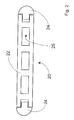
- Figure 3 shows the metal vane body 22.
- the metal vane body 22 comprises rectangular and/or elongated radial recesses 27 arranged in series in axial direction of the vane 20 in order to reduce the weight of the vane 20.
Landscapes
- Engineering & Computer Science (AREA)
- Mechanical Engineering (AREA)
- General Engineering & Computer Science (AREA)
- Rotary Pumps (AREA)
Abstract
Description
- The present invention refers to an automotive vacuum vane pump which comprises a housing with a radially moveable rotor vane.
- Vacuum vane pumps of the state of the art comprise one or more vanes of a constant length, wherein the vane tips slide at a pump chamber wall. The vane separates the pump chamber in different rooms, for example in case of vacuum pump with a single vane assembly in an intake room and a pressure room. Vacuum vane pumps are used in automotive applications as a supply device for servo brake devices, valves etc.
- The pump comprises a housing with a radially moveable rotor vane, wherein the one-pieced metal vane has a constant length and wherein the vane tips slide at a pump chamber wall. A vacuum vane pump with a relatively heavy metal vane tends to vibrations due to high centrifugal forces, and therefore the pump is subject to high energy consumptions and mechanical wear. Another relevant problem is the abrasion of the vane ends or tips and the pump chamber wall.
-
DE 10 2005 058 129 A1 discloses a vacuum vane pump construction with a single thermosetting plastic vane, wherein the complete vane is made of a fiber reinforced material. The manufacturing of these vanes is complex and cost-intensive, and the vane ends are subject to abrasion so that the vane length decreases during the lifetime of the pump. - It is an object of the present invention to provide a vane pump with improved long life properties.
- This object is solved with an automotive vacuum vane pump with the features of claim 1.
- The automotive vacuum vane pump according to claim 1 comprises a housing with a radially moveable rotor vane, wherein the vane consists of at least two components, i.e. a metal vane body and one or two separate plastic vane tips at one or both ends of the vane. Both, the metal vane body and the plastic vane tips can be optimized with respect to their special function. The metal vane body material, for example, can have a high stability. The plastic tips can have a hardness which is less than the pump chamber wall hardness. Therefore, the abrasion of the metal pump chamber wall can be reduced significantly.
- Preferably, the vane body is made out of a light metal, preferably of an aluminum alloy which is produced via a continuous casting process. Aluminum alloy is a lightweight material and comprises the benefit of an enhanced stability whereby the weight remains unchanged in comparison with pure aluminum. The continuously cast material provides an inexpensive production due to the inherently lower cost of continuous, standardized production of the product.
- According to a preferred embodiment of the invention, the metal vane body comprises axial recesses arranged in series in longitudinal direction of the vane, i.e. in radial direction of the rotor. This causes a weight reduction whereby the rigidity and the stability of the vane remains unchanged. Therefore, the automotive vacuum vane pump ensures long life properties and functionality, respectively.
- Alternatively, the metal vane body comprises radial, i.e. longitudinal recesses arranged in series in axial direction of the vane. This causes a weight reduction whereby the rigidity and the stability of the vane remains unchanged. Moreover, the radial recesses which are arranged in axial direction cause a more stiff vane body in the direction of the main bending load.
- The vane tips are preferably made out of a thermosetting plastic which is fiber reinforced. The vane tips are more elastic and stronger in comparison to pure thermosetting plastic.
- According to a preferred embodiment of the invention, the vane tip is provided moveable in longitudinal direction at the vane body, i.e. moveable in radial direction of the rotor. The movability of the vane tip ensures air-tightness in case of abrasion.
- According to a preferred embodiment of the invention, the combination of movable plastic tips and an aluminum alloy vane body leads to a lower impact of the centrifugal forces, which are primarily responsible for abrasion in view of maximum rotating speeds between 5000 and 10000 rpm. This assembly causes at one hand a reduced abrasion of said plastic vane tips and on the other hand ensures air-tightness.
- Preferably, the vane tip is form-fitted hold at the vane body. The section of the vane tips has a mushroom form. The vane tips provide a semicircle head and a flat shaft. The flat shaft is arranged in a form-fitted recess of the vane body. This embodiment provides a torque-proof support of the vane tip at the vane body. The longitudinal movability of the tip provides an air-tight pump chamber separation during the life time of the pump.
- The following is a detailed description of an embodiment of the invention with reference to the drawings, in which:
-
Figure 1 shows an automotive vacuum vane pump without a cover plate from the plan view, -
Figure 2 shows a vane body with two moveable tips at the end of the vane, and -
Figure 3 shows a vane body with radial recesses arranged in line in axial direction. - In
figure 1 , avacuum vane pump 10 is shown in a plan view. The automotivevacuum vane pump 10 comprises ametal housing 40 with an inlet opening 47 and an outlet opening 48. Thehousing 40 surrounds thepump chamber 44. Thepump chamber 44 is surrounded by a non-cylindricalpump chamber wall 42. - The
pump chamber 44 comprises acircular pump rotor 30. Thepump rotor 30 is with itscircumferential rotor wall 32 arranged adjacent to theside wall 43 of thepump chamber 44, whereby a protrusion (not shown) of thepump rotor 30 protrudes axially to the outside of theside wall 43. The protrusion of thepump rotor 30 can be rotated by a pump motor (not shown). - The
pump rotor 30 has a radial continuous vane guiding opening 26, wherein a radiallymoveable vane 20 is mounted. Thevane 20 comprises ametal vane body 22 with two with respect to therotor 30 radially moveableplastic vane tips 24 at the ends of themetal vane body 22, whereby theplastic vane tips 24 slide at thepump chamber wall 42. Thevane tips 24 are arranged torque-proof with respect to the longitudinal axis of the vane 2°. - The
vane 20 separates thepump chamber 44 into anintake room 45 and apressure room 46, because therotor wall 32 slides permanently at thepump chamber wall 42, and thereby separates theintake room 45 and thepressure room 46 air-tight. - As
figure 2 shows, thevane 20 comprises ametal vane body 22 and two radially, i.e. in the longitudinal direction of themetal vane body 22, moveableplastic vane tips 24 at the end of thevane 20. Themetal vane body 22 comprises rectangular and/or elongatedaxial recesses 25 arranged in series in radial direction of thevane 20 in order to reduce the weight of thevane 20. -
Figure 3 shows themetal vane body 22. Themetal vane body 22 comprises rectangular and/or elongatedradial recesses 27 arranged in series in axial direction of thevane 20 in order to reduce the weight of thevane 20.
Claims (8)
- Automotive vacuum vane pump (10) with a radially moveable rotor vane (20), the vane (20) comprising:a metal vane body (22), anda separate vane tip (24) at one end of the vane (20), whereinthe vane tip (24) is made out of plastic.
- Automotive vacuum vane pump (10) of claim 1, wherein the metal vane body (22) is made out of a light metal, preferably of an aluminum alloy.
- Automotive vacuum vane pump (10) of claim 1 or 2, wherein the vane body (22) comprises axial recesses (25) arranged in series in radial direction of the vane (20).
- Automotive vacuum vane pump (10) of claim 1 or 2, wherein the vane body (22) comprises radial recesses (27) arranged in series in axial direction of the vane (20).
- Automotive vacuum vane pump (10) of one of the preceding claims, wherein the vane tip (24) is made out of fiber reinforced polymer.
- Automotive vacuum vane pump (10) of claim 5, wherein the fiber reinforced polymer is a thermosetting plastic reinforced with carbon fiber.
- Automotive vacuum vane pump (10) of one of the preceding claims, wherein the vane tip (24) is provided radially moveable at the vane body (22).
- Automotive vacuum vane pump (10) of one of the preceding claims; wherein the vane tip (24) is form-fitted hold at the vane body (22).
Priority Applications (1)
| Application Number | Priority Date | Filing Date | Title |
|---|---|---|---|
| EP20090170219 EP2299055B1 (en) | 2009-09-14 | 2009-09-14 | Automotive vacuum vane pump |
Applications Claiming Priority (1)
| Application Number | Priority Date | Filing Date | Title |
|---|---|---|---|
| EP20090170219 EP2299055B1 (en) | 2009-09-14 | 2009-09-14 | Automotive vacuum vane pump |
Publications (2)
| Publication Number | Publication Date |
|---|---|
| EP2299055A1 true EP2299055A1 (en) | 2011-03-23 |
| EP2299055B1 EP2299055B1 (en) | 2014-11-12 |
Family
ID=41683399
Family Applications (1)
| Application Number | Title | Priority Date | Filing Date |
|---|---|---|---|
| EP20090170219 Active EP2299055B1 (en) | 2009-09-14 | 2009-09-14 | Automotive vacuum vane pump |
Country Status (1)
| Country | Link |
|---|---|
| EP (1) | EP2299055B1 (en) |
Cited By (2)
| Publication number | Priority date | Publication date | Assignee | Title |
|---|---|---|---|---|
| CN105114308A (en) * | 2015-09-11 | 2015-12-02 | 裕克施乐塑料制品(太仓)有限公司 | Novel vacuum pump blade and vacuum pump |
| CN105156324A (en) * | 2015-09-11 | 2015-12-16 | 裕克施乐塑料制品(太仓)有限公司 | Novel plastic vacuum pump blade and vacuum pump |
Citations (7)
| Publication number | Priority date | Publication date | Assignee | Title |
|---|---|---|---|---|
| EP0264778A2 (en) * | 1986-10-18 | 1988-04-27 | B a r m a g AG | Vane pump |
| US5560741A (en) | 1994-06-28 | 1996-10-01 | Edwards; Thomas C. | Non-contact vane-type fluid displacement machine with rotor and vane positioning |
| WO2000073629A1 (en) | 1999-05-27 | 2000-12-07 | Kirtley Kevin R | Rotary vane pump with continuous carbon fiber reinforced polyetheretherketone (peek) vanes |
| EP1134417A2 (en) | 2000-03-15 | 2001-09-19 | Joma-Hydromechanic GmbH | Positive displacement pump |
| DE102004034921B3 (en) | 2004-07-09 | 2005-12-29 | Joma-Hydromechanic Gmbh | A single-blade |
| DE102005058129A1 (en) | 2005-11-30 | 2007-05-31 | Joma-Hydromechanic Gmbh | Vacuum pump, comprises vane, pump housing and rotor rotatably mounted whereby vane has constant length and is one-piece design and is made of thermosetting plastic |
| WO2007140759A1 (en) * | 2006-06-07 | 2007-12-13 | Ixetic Hückeswagen Gmbh | Vane cell pump |
-
2009
- 2009-09-14 EP EP20090170219 patent/EP2299055B1/en active Active
Patent Citations (7)
| Publication number | Priority date | Publication date | Assignee | Title |
|---|---|---|---|---|
| EP0264778A2 (en) * | 1986-10-18 | 1988-04-27 | B a r m a g AG | Vane pump |
| US5560741A (en) | 1994-06-28 | 1996-10-01 | Edwards; Thomas C. | Non-contact vane-type fluid displacement machine with rotor and vane positioning |
| WO2000073629A1 (en) | 1999-05-27 | 2000-12-07 | Kirtley Kevin R | Rotary vane pump with continuous carbon fiber reinforced polyetheretherketone (peek) vanes |
| EP1134417A2 (en) | 2000-03-15 | 2001-09-19 | Joma-Hydromechanic GmbH | Positive displacement pump |
| DE102004034921B3 (en) | 2004-07-09 | 2005-12-29 | Joma-Hydromechanic Gmbh | A single-blade |
| DE102005058129A1 (en) | 2005-11-30 | 2007-05-31 | Joma-Hydromechanic Gmbh | Vacuum pump, comprises vane, pump housing and rotor rotatably mounted whereby vane has constant length and is one-piece design and is made of thermosetting plastic |
| WO2007140759A1 (en) * | 2006-06-07 | 2007-12-13 | Ixetic Hückeswagen Gmbh | Vane cell pump |
Cited By (3)
| Publication number | Priority date | Publication date | Assignee | Title |
|---|---|---|---|---|
| CN105114308A (en) * | 2015-09-11 | 2015-12-02 | 裕克施乐塑料制品(太仓)有限公司 | Novel vacuum pump blade and vacuum pump |
| CN105156324A (en) * | 2015-09-11 | 2015-12-16 | 裕克施乐塑料制品(太仓)有限公司 | Novel plastic vacuum pump blade and vacuum pump |
| CN105156324B (en) * | 2015-09-11 | 2018-09-04 | 裕克施乐塑料制品(太仓)有限公司 | A kind of novel plastic vacuum pump vanes and vacuum pump |
Also Published As
| Publication number | Publication date |
|---|---|
| EP2299055B1 (en) | 2014-11-12 |
Similar Documents
| Publication | Publication Date | Title |
|---|---|---|
| US9631623B2 (en) | Stepped parting joint on a transmission housing of a fluid machine | |
| CN102171459B (en) | There is the turbosupercharger of insert plate | |
| EP2677118B1 (en) | Automotive volumetric vacuum pump | |
| CN107850080A (en) | Centrifugal compressor with interstage seal arrangement | |
| US20140064934A1 (en) | Diffuser vane for a compressor device and diffuser assembly comprised thereof | |
| JP6379568B2 (en) | Scroll and turbo compressor | |
| EP2299055B1 (en) | Automotive vacuum vane pump | |
| US20120186247A1 (en) | Turbocharger with Reversed Compressor Volute Optionally Integrated into the Center Housing | |
| US7938619B2 (en) | Turbo vacuum pump | |
| JP6151710B2 (en) | Impeller for liquid ring vacuum pump and liquid ring vacuum pump | |
| EP2249040B1 (en) | Improved monovane vacuum pump | |
| EP1703136B1 (en) | Lateral channel compressor | |
| EP3118462A1 (en) | Centrifugal compressor and centrifugal facility having same | |
| EP2472114A1 (en) | Scroll fluid machine | |
| CN106402013B (en) | Pump and pump assembling method | |
| WO2011070589A3 (en) | Conical shape single rotor compressor | |
| US20130064659A1 (en) | Centrifugal compressor | |
| KR102083925B1 (en) | A compressing apparatus | |
| EP3196479A1 (en) | Centrifugal compressor | |
| US8398362B2 (en) | Turbomolecular pump | |
| GB2520825A (en) | Air vane wheel for conveying air having an air bearing and radial compressor having an air vane wheel | |
| JP2007162483A (en) | Overflow pump | |
| JP2015094254A (en) | Centrifugal compressor | |
| JP2002048083A (en) | Multi-stage slurry pump | |
| KR101031157B1 (en) | Vane pump |
Legal Events
| Date | Code | Title | Description |
|---|---|---|---|
| PUAI | Public reference made under article 153(3) epc to a published international application that has entered the european phase |
Free format text: ORIGINAL CODE: 0009012 |
|
| AK | Designated contracting states |
Kind code of ref document: A1 Designated state(s): AT BE BG CH CY CZ DE DK EE ES FI FR GB GR HR HU IE IS IT LI LT LU LV MC MK MT NL NO PL PT RO SE SI SK SM TR |
|
| AX | Request for extension of the european patent |
Extension state: AL BA RS |
|
| 17P | Request for examination filed |
Effective date: 20110303 |
|
| 17Q | First examination report despatched |
Effective date: 20110328 |
|
| GRAP | Despatch of communication of intention to grant a patent |
Free format text: ORIGINAL CODE: EPIDOSNIGR1 |
|
| INTG | Intention to grant announced |
Effective date: 20140715 |
|
| GRAS | Grant fee paid |
Free format text: ORIGINAL CODE: EPIDOSNIGR3 |
|
| GRAA | (expected) grant |
Free format text: ORIGINAL CODE: 0009210 |
|
| AK | Designated contracting states |
Kind code of ref document: B1 Designated state(s): AT BE BG CH CY CZ DE DK EE ES FI FR GB GR HR HU IE IS IT LI LT LU LV MC MK MT NL NO PL PT RO SE SI SK SM TR |
|
| REG | Reference to a national code |
Ref country code: GB Ref legal event code: FG4D |
|
| REG | Reference to a national code |
Ref country code: CH Ref legal event code: EP |
|
| REG | Reference to a national code |
Ref country code: AT Ref legal event code: REF Ref document number: 695909 Country of ref document: AT Kind code of ref document: T Effective date: 20141115 |
|
| REG | Reference to a national code |
Ref country code: IE Ref legal event code: FG4D |
|
| REG | Reference to a national code |
Ref country code: DE Ref legal event code: R096 Ref document number: 602009027667 Country of ref document: DE Effective date: 20141224 |
|
| REG | Reference to a national code |
Ref country code: NL Ref legal event code: VDEP Effective date: 20141112 |
|
| REG | Reference to a national code |
Ref country code: AT Ref legal event code: MK05 Ref document number: 695909 Country of ref document: AT Kind code of ref document: T Effective date: 20141112 |
|
| PG25 | Lapsed in a contracting state [announced via postgrant information from national office to epo] |
Ref country code: IS Free format text: LAPSE BECAUSE OF FAILURE TO SUBMIT A TRANSLATION OF THE DESCRIPTION OR TO PAY THE FEE WITHIN THE PRESCRIBED TIME-LIMIT Effective date: 20150312 Ref country code: NO Free format text: LAPSE BECAUSE OF FAILURE TO SUBMIT A TRANSLATION OF THE DESCRIPTION OR TO PAY THE FEE WITHIN THE PRESCRIBED TIME-LIMIT Effective date: 20150212 Ref country code: LT Free format text: LAPSE BECAUSE OF FAILURE TO SUBMIT A TRANSLATION OF THE DESCRIPTION OR TO PAY THE FEE WITHIN THE PRESCRIBED TIME-LIMIT Effective date: 20141112 Ref country code: ES Free format text: LAPSE BECAUSE OF FAILURE TO SUBMIT A TRANSLATION OF THE DESCRIPTION OR TO PAY THE FEE WITHIN THE PRESCRIBED TIME-LIMIT Effective date: 20141112 Ref country code: FI Free format text: LAPSE BECAUSE OF FAILURE TO SUBMIT A TRANSLATION OF THE DESCRIPTION OR TO PAY THE FEE WITHIN THE PRESCRIBED TIME-LIMIT Effective date: 20141112 Ref country code: NL Free format text: LAPSE BECAUSE OF FAILURE TO SUBMIT A TRANSLATION OF THE DESCRIPTION OR TO PAY THE FEE WITHIN THE PRESCRIBED TIME-LIMIT Effective date: 20141112 Ref country code: PT Free format text: LAPSE BECAUSE OF FAILURE TO SUBMIT A TRANSLATION OF THE DESCRIPTION OR TO PAY THE FEE WITHIN THE PRESCRIBED TIME-LIMIT Effective date: 20150312 |
|
| PG25 | Lapsed in a contracting state [announced via postgrant information from national office to epo] |
Ref country code: PL Free format text: LAPSE BECAUSE OF FAILURE TO SUBMIT A TRANSLATION OF THE DESCRIPTION OR TO PAY THE FEE WITHIN THE PRESCRIBED TIME-LIMIT Effective date: 20141112 Ref country code: AT Free format text: LAPSE BECAUSE OF FAILURE TO SUBMIT A TRANSLATION OF THE DESCRIPTION OR TO PAY THE FEE WITHIN THE PRESCRIBED TIME-LIMIT Effective date: 20141112 Ref country code: CY Free format text: LAPSE BECAUSE OF FAILURE TO SUBMIT A TRANSLATION OF THE DESCRIPTION OR TO PAY THE FEE WITHIN THE PRESCRIBED TIME-LIMIT Effective date: 20141112 Ref country code: LV Free format text: LAPSE BECAUSE OF FAILURE TO SUBMIT A TRANSLATION OF THE DESCRIPTION OR TO PAY THE FEE WITHIN THE PRESCRIBED TIME-LIMIT Effective date: 20141112 Ref country code: HR Free format text: LAPSE BECAUSE OF FAILURE TO SUBMIT A TRANSLATION OF THE DESCRIPTION OR TO PAY THE FEE WITHIN THE PRESCRIBED TIME-LIMIT Effective date: 20141112 Ref country code: GR Free format text: LAPSE BECAUSE OF FAILURE TO SUBMIT A TRANSLATION OF THE DESCRIPTION OR TO PAY THE FEE WITHIN THE PRESCRIBED TIME-LIMIT Effective date: 20150213 Ref country code: SE Free format text: LAPSE BECAUSE OF FAILURE TO SUBMIT A TRANSLATION OF THE DESCRIPTION OR TO PAY THE FEE WITHIN THE PRESCRIBED TIME-LIMIT Effective date: 20141112 |
|
| PG25 | Lapsed in a contracting state [announced via postgrant information from national office to epo] |
Ref country code: CZ Free format text: LAPSE BECAUSE OF FAILURE TO SUBMIT A TRANSLATION OF THE DESCRIPTION OR TO PAY THE FEE WITHIN THE PRESCRIBED TIME-LIMIT Effective date: 20141112 Ref country code: RO Free format text: LAPSE BECAUSE OF FAILURE TO SUBMIT A TRANSLATION OF THE DESCRIPTION OR TO PAY THE FEE WITHIN THE PRESCRIBED TIME-LIMIT Effective date: 20141112 Ref country code: DK Free format text: LAPSE BECAUSE OF FAILURE TO SUBMIT A TRANSLATION OF THE DESCRIPTION OR TO PAY THE FEE WITHIN THE PRESCRIBED TIME-LIMIT Effective date: 20141112 Ref country code: SK Free format text: LAPSE BECAUSE OF FAILURE TO SUBMIT A TRANSLATION OF THE DESCRIPTION OR TO PAY THE FEE WITHIN THE PRESCRIBED TIME-LIMIT Effective date: 20141112 Ref country code: EE Free format text: LAPSE BECAUSE OF FAILURE TO SUBMIT A TRANSLATION OF THE DESCRIPTION OR TO PAY THE FEE WITHIN THE PRESCRIBED TIME-LIMIT Effective date: 20141112 |
|
| REG | Reference to a national code |
Ref country code: DE Ref legal event code: R097 Ref document number: 602009027667 Country of ref document: DE |
|
| PLBE | No opposition filed within time limit |
Free format text: ORIGINAL CODE: 0009261 |
|
| STAA | Information on the status of an ep patent application or granted ep patent |
Free format text: STATUS: NO OPPOSITION FILED WITHIN TIME LIMIT |
|
| 26N | No opposition filed |
Effective date: 20150813 |
|
| PG25 | Lapsed in a contracting state [announced via postgrant information from national office to epo] |
Ref country code: SI Free format text: LAPSE BECAUSE OF FAILURE TO SUBMIT A TRANSLATION OF THE DESCRIPTION OR TO PAY THE FEE WITHIN THE PRESCRIBED TIME-LIMIT Effective date: 20141112 |
|
| PG25 | Lapsed in a contracting state [announced via postgrant information from national office to epo] |
Ref country code: LU Free format text: LAPSE BECAUSE OF FAILURE TO SUBMIT A TRANSLATION OF THE DESCRIPTION OR TO PAY THE FEE WITHIN THE PRESCRIBED TIME-LIMIT Effective date: 20150914 Ref country code: MC Free format text: LAPSE BECAUSE OF FAILURE TO SUBMIT A TRANSLATION OF THE DESCRIPTION OR TO PAY THE FEE WITHIN THE PRESCRIBED TIME-LIMIT Effective date: 20141112 |
|
| REG | Reference to a national code |
Ref country code: CH Ref legal event code: PL |
|
| GBPC | Gb: european patent ceased through non-payment of renewal fee |
Effective date: 20150914 |
|
| REG | Reference to a national code |
Ref country code: IE Ref legal event code: MM4A |
|
| PG25 | Lapsed in a contracting state [announced via postgrant information from national office to epo] |
Ref country code: LI Free format text: LAPSE BECAUSE OF NON-PAYMENT OF DUE FEES Effective date: 20150930 Ref country code: GB Free format text: LAPSE BECAUSE OF NON-PAYMENT OF DUE FEES Effective date: 20150914 Ref country code: IE Free format text: LAPSE BECAUSE OF NON-PAYMENT OF DUE FEES Effective date: 20150914 Ref country code: CH Free format text: LAPSE BECAUSE OF NON-PAYMENT OF DUE FEES Effective date: 20150930 |
|
| REG | Reference to a national code |
Ref country code: FR Ref legal event code: PLFP Year of fee payment: 8 |
|
| PG25 | Lapsed in a contracting state [announced via postgrant information from national office to epo] |
Ref country code: MT Free format text: LAPSE BECAUSE OF FAILURE TO SUBMIT A TRANSLATION OF THE DESCRIPTION OR TO PAY THE FEE WITHIN THE PRESCRIBED TIME-LIMIT Effective date: 20141112 |
|
| PG25 | Lapsed in a contracting state [announced via postgrant information from national office to epo] |
Ref country code: SM Free format text: LAPSE BECAUSE OF FAILURE TO SUBMIT A TRANSLATION OF THE DESCRIPTION OR TO PAY THE FEE WITHIN THE PRESCRIBED TIME-LIMIT Effective date: 20141112 Ref country code: BG Free format text: LAPSE BECAUSE OF FAILURE TO SUBMIT A TRANSLATION OF THE DESCRIPTION OR TO PAY THE FEE WITHIN THE PRESCRIBED TIME-LIMIT Effective date: 20141112 Ref country code: HU Free format text: LAPSE BECAUSE OF FAILURE TO SUBMIT A TRANSLATION OF THE DESCRIPTION OR TO PAY THE FEE WITHIN THE PRESCRIBED TIME-LIMIT; INVALID AB INITIO Effective date: 20090914 |
|
| PG25 | Lapsed in a contracting state [announced via postgrant information from national office to epo] |
Ref country code: TR Free format text: LAPSE BECAUSE OF FAILURE TO SUBMIT A TRANSLATION OF THE DESCRIPTION OR TO PAY THE FEE WITHIN THE PRESCRIBED TIME-LIMIT Effective date: 20141112 |
|
| REG | Reference to a national code |
Ref country code: FR Ref legal event code: PLFP Year of fee payment: 9 |
|
| PG25 | Lapsed in a contracting state [announced via postgrant information from national office to epo] |
Ref country code: BE Free format text: LAPSE BECAUSE OF FAILURE TO SUBMIT A TRANSLATION OF THE DESCRIPTION OR TO PAY THE FEE WITHIN THE PRESCRIBED TIME-LIMIT Effective date: 20141112 |
|
| PG25 | Lapsed in a contracting state [announced via postgrant information from national office to epo] |
Ref country code: MK Free format text: LAPSE BECAUSE OF FAILURE TO SUBMIT A TRANSLATION OF THE DESCRIPTION OR TO PAY THE FEE WITHIN THE PRESCRIBED TIME-LIMIT Effective date: 20141112 |
|
| REG | Reference to a national code |
Ref country code: FR Ref legal event code: PLFP Year of fee payment: 10 |
|
| REG | Reference to a national code |
Ref country code: DE Ref legal event code: R082 Ref document number: 602009027667 Country of ref document: DE Representative=s name: TERPATENT PARTGMBB, DE Ref country code: DE Ref legal event code: R082 Ref document number: 602009027667 Country of ref document: DE Representative=s name: TERPATENT PATENTANWAELTE TER SMITTEN EBERLEIN-, DE |
|
| PGFP | Annual fee paid to national office [announced via postgrant information from national office to epo] |
Ref country code: DE Payment date: 20240919 Year of fee payment: 16 |
|
| PGFP | Annual fee paid to national office [announced via postgrant information from national office to epo] |
Ref country code: FR Payment date: 20240930 Year of fee payment: 16 |
|
| PGFP | Annual fee paid to national office [announced via postgrant information from national office to epo] |
Ref country code: IT Payment date: 20240930 Year of fee payment: 16 |