EP2299038A2 - Lock assembly and method of assembling the lock - Google Patents
Lock assembly and method of assembling the lock Download PDFInfo
- Publication number
- EP2299038A2 EP2299038A2 EP10177157A EP10177157A EP2299038A2 EP 2299038 A2 EP2299038 A2 EP 2299038A2 EP 10177157 A EP10177157 A EP 10177157A EP 10177157 A EP10177157 A EP 10177157A EP 2299038 A2 EP2299038 A2 EP 2299038A2
- Authority
- EP
- European Patent Office
- Prior art keywords
- cylinder
- lock
- anchoring
- house
- housing
- Prior art date
- Legal status (The legal status is an assumption and is not a legal conclusion. Google has not performed a legal analysis and makes no representation as to the accuracy of the status listed.)
- Withdrawn
Links
- 238000000034 method Methods 0.000 title claims abstract description 15
- 238000004873 anchoring Methods 0.000 claims abstract description 106
- 238000003780 insertion Methods 0.000 claims description 17
- 230000037431 insertion Effects 0.000 claims description 17
- 230000000903 blocking effect Effects 0.000 description 15
- 238000010276 construction Methods 0.000 description 3
- 238000004519 manufacturing process Methods 0.000 description 3
- 238000003801 milling Methods 0.000 description 2
- 230000007704 transition Effects 0.000 description 1
- 235000012431 wafers Nutrition 0.000 description 1
Images

Classifications
-
- E—FIXED CONSTRUCTIONS
- E05—LOCKS; KEYS; WINDOW OR DOOR FITTINGS; SAFES
- E05B—LOCKS; ACCESSORIES THEREFOR; HANDCUFFS
- E05B9/00—Lock casings or latch-mechanism casings ; Fastening locks or fasteners or parts thereof to the wing
- E05B9/08—Fastening locks or fasteners or parts thereof, e.g. the casings of latch-bolt locks or cylinder locks to the wing
- E05B9/084—Fastening of lock cylinders, plugs or cores
-
- E—FIXED CONSTRUCTIONS
- E05—LOCKS; KEYS; WINDOW OR DOOR FITTINGS; SAFES
- E05B—LOCKS; ACCESSORIES THEREFOR; HANDCUFFS
- E05B9/00—Lock casings or latch-mechanism casings ; Fastening locks or fasteners or parts thereof to the wing
- E05B9/08—Fastening locks or fasteners or parts thereof, e.g. the casings of latch-bolt locks or cylinder locks to the wing
- E05B9/084—Fastening of lock cylinders, plugs or cores
- E05B9/086—Fastening of rotors, plugs or cores to an outer stator
Definitions
- the invention relates to cylinder locks comprising a lock cylinder having an attachment for attaching to a lock housing, especially a lock cylinder wherein a cylinder core is arranged in a cylinder housing.
- the invention also relates to assembling of a lock cylinder and a housing of the lock.
- the invention relates to lock cylinders comprising a cylinder core arranged in a housing of the lock cylinder.
- a lock cylinder normally comprises locking pins in pin channels extending from housing to cylinder core.
- the locking pins prevent rotation of the cylinder core in relation to the cylinder housing.
- the locking pins are arranged to be effected by a key when entering into a key hole and further in a key channel through the cylinder core. With the correct key the locking pins are lifted so that the cylinder core can rotate inside the housing.
- the cylinder core does not move in the axial direction of the cylinder house when the key is inserted into the lock, instead they are kept mutually unmoving in the longitudinal direction also with the correct key inserted in the lock.
- a locking device in the Swedish patent SE526189 (also W02005/049945 ) a locking device is shown that comprises a lock housing (10, 20 see abstract and figure 4 ), and at the side of the housing a lock cylinder 40 is arranged comprising a cylinder house 41 and a cylinder core (plug 42) which is rotatably arranged in an opening 41a of the cylinder house.
- a mounting hole 22 in the lock house is adapted to receive an anchoring part 42c at the inner end of the cylinder plug. The movement of the cylinder core in the axial direction is prevented in a fixating position of the cylinder core when the anchoring part engages the housing of the lock.
- the outer envelope surface of the cylinder core (see especially page 7 line 4-22) is provided with a machined groove 42b traversing the axial direction.
- This groove runs a predetermined distance around the cylinder core and is arranged to cooperate with a latch pin 44, which during assembly is fixed into position in a hole 41b in the cylinder house.
- the latch pin 44 locks the movement of the inserted cylinder core in the axial direction, by means of the latch pin engaging the groove so that the axial movement of the core is prevented.
- An additional function of the latch pin is to limit the rotation of the cylinder core when a key is inserted in the lock (page 7, line 23-25).
- An aim of the invention is to provide a locking device comprising a cylinder lock having a lock cylinder attached to a lock housing, which lock cylinder shows a cylinder core arranged in a cylinder house, which cylinder core is rotatably fastened in the cylinder house so that they are kept mutually unmovable in the axial direction of the cylinder core.
- An aim is to also provide a lock contributing to a comparatively efficient manufacturing and assembly.
- An aim is to be able to fasten the lock cylinder to the lock housing in a simple way, so that the lock cylinder can not move in the axial direction in relation to the lock housing.
- An aim is to be able to fasten the cylinder core in a simple way to the cylinder house, so that the cylinder core cannot move in its axial direction in relation to the cylinder house.
- the invention defines a lock device that is an assembly of a lock housing and a lock cylinder, which lock cylinder comprises a cylinder house and a cylinder core.
- the lock assembly comprises a lock housing and a lock cylinder, and the lock housing is provided with at least one anchoring means that extends out of the lock housing, the lock cylinder is provided with an anchoring hole, or anchoring holes, for the anchoring means.
- the lock cylinder is also provided with an assembling hole which is joined with the anchoring hole, the lock assembly further comprises a securing element, which is adapted for being arranged in the assembling hole and extend into the anchoring hole.
- the anchoring means and the securing element are formed to engage when the anchoring means are arranged in the anchoring hole and the securing element is arranged in the assembling hole, so that the lock housing is attached to the lock cylinder.
- the securing element is suitably adapted to prevent removal of the anchoring means from the anchoring holes.
- the anchoring means are preferably provided with head portions that make their width larger and the securing element is arranged between the head portions of the anchoring means and the lock housing so that disassembling is prevented.
- the lock cylinder comprises a cylinder core and a cylinder house provided with a cylindrical space, wherein the cylinder core is adapted to be arranged inserted into the cylindrical space.
- the cylinder core is provided with a groove which provides a passage through the lock cylinder from the assembling hole when the cylinder core is arranged in the cylinder house.
- the groove in the cylinder core is intended to be positioned inside the assembling hole and the groove can in this way be reached from outside the lock cylinder through the assembling hole.
- the securing element is adapted to cooperate with the groove of the cylinder core, when the cylinder core is positioned inserted in the hole of the lock housing in the intended use position.
- the securing element immobilizes the axial movement of the inserted cylinder core.
- the securing element provides, apart from securing the lock cylinder to the lock house, also a fastening of the cylinder core to the cylinder house.
- An alternative to this double function is to use two separate securing elements, one for securing the lock housing to the lock cylinder, and another for securing the cylinder core in the cylinder house.
- the groove is formed in the envelope surface of the cylinder core and extends one turn around the cylinder core.
- a groove in the core can be made by a turning machine.
- the groove is formed in the envelope surface of the cylinder core and extends a fraction of a turn around the cylinder core, such as approximately half a turn. Accordingly the securing element provide a further function in that it in cooperation with the groove creates a limit to the rotation of the cylinder core, so that the turning of an inserted key is limited to only a portion of a turn, such as a quarter of a turn.
- a groove can for example be machine cut into the enveloping surface of the core by means of a milling machine.
- a pin constitutes the securing element. This provides a simple construction and simple assembling.
- the pin is preferably provided with grooves for cooperation with an inside of the hole of the cylinder house, so that it is secured in the assembled position in the assembling hole.
- the anchoring means comprises a body portion and a head portion, and the anchoring means is formed fixed to the lock housing to be inserted into the anchoring hole with the head section entering before the body section.
- the invention give suitable examples of embodiments, wherein the anchoring holes are arranged in the cylinder house and wherein the assembling hole extends from an outside of the cylinder house into the cylindrical space.
- the assembling hole is a through hole and extends through the cylinder lock. This facilitates disassembling of the assembly, for example a securing element of pin shape can be pushed straight out through the hole.
- the invention also provides a method for assembling a lock assembly where a lock cylinder is secured to a lock housing, which lock housing comprises at least one anchoring means for anchoring the lock housing to the cylinder house.
- the method includes anchoring the lock cylinder to the lock housing so that the lock cylinder is secured to the lock housing in its axial direction.
- the method comprises insertion of the anchoring means into the lock cylinder, and that the securing of the lock housing, in the axial direction, to the lock cylinder includes insertion, into the lock cylinder, of a securing element reaching to the anchoring means.
- the insertion of the securing element is performed across the axial direction.
- An embodiment the insertion of the anchoring means of the lock housing into the anchoring holes of the cylinder house is performed in the axial direction.
- the method includes insertion of the securing element, so that the securing element in its inserted position is located in a groove in a cylinder core arranged in the cylinder lock. Thereby also the cylinder core is secured in its axial direction.
- the method of assembling is performed with a lock cylinder comprising a cylinder house provided with anchoring holes.
- the insertion of the anchoring means of the lock house into the lock cylinder is then performed by inserting the anchoring means into the anchoring holes provided in the cylinder house. This insertion is performed in the axial direction of the lock cylinder.
- the method preferably comprises that the cylinder core is inserted into the cylinder house in an axial direction, and that the cylinder core, the cylinder house and the lock house are secured to each other in the axial direction.
- This is preferably performed by inserting a securing element through the cylinder house to the cylinder core and the anchoring means.
- a securing element provided with any of the previously mentioned grooves.
- the cylinder house and the cylinder core cooperate so that the cylinder core is rotatably mounted in a bearing, i.e. so that it can be rotated by an inserted key and be held axially in relation to the cylinder house, by means of the securing element being arranged in the assembling hole and extending at least partially past the cylinder core in or through the groove.
- a securing pin as securing element for keeping together both the lock house, the cylinder house and the cylinder core contributes to an especially simple construction and simple assembling of the included parts to a cylinder lock.
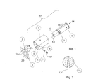
- a first embodiment in figure 1 illustrates a lock assembly in accordance with the invention.
- the lock assembly comprises a lock housing 1, which is only partly illustrated by a cover plate in figure 1 , and a lock cylinder 11.
- the lock housing 1 is suitably provided with a mechanism for acting on a locking latch or locking bolt ( figure 5 illustrates a lock housing with locking bolt 16) and is operatively connected to such a locking latch or bolt, which in turn is adapted for locking a door, such as a door of a locker or cabinet.
- the cover plate arranged on the lock housing 1 is provided with two anchoring pins 2 that are adapted to anchor the cylinder house 3 of the cylinder lock 11 to the lock housing 1.
- the lock housing comprises only one anchoring means.
- the anchoring pins 2 are fixed in the cover plate / lock housing by means of, for example, heads 2c and securingly stamped in the lock housing, or can be designed as a molded part of the cover plate of the lock housing.
- Each anchoring pin 2 is made of a cylindrical body 2a that extends essentially perpendicular out from of cover plate 1 and is ended with a head 2b that has a larger cross section than the body 2a.
- the anchoring pins 2 are adapted to be inserted through a front piece or gable of a cylinder house 3 for attaching the cover plate of the lock housing 1 to the cylinder house 3.
- the two anchoring pins are parallel and prevent, when they have been inserted in the anchoring holes, that the lock housing 1 and cylinder house 3 rotate in relation to each other.
- the anchoring pins cooperates with a securing element 7, which is positioned engaging with the head 2b, at the transition of the head towards the body 2a, and cooperates in engagement with an underside of the head to hold the anchoring pins 2 and thereby the lock housing fixed to the cylinder house 3.
- the lock house 1 is also provided with an opening 20 for a cylinder core 8 of the cylinder lock 11.
- the cylinder house 3 comprises anchoring holes 4 for the anchoring pins 2, the anchoring holes 4 are provided in a gable that is intended to face the lock housing 1.
- the anchoring pins 2 are inserted in the anchoring holes 4 and the securing element 7 secures the anchoring pins 2 in the inserted position in the anchoring holes 4, so that the anchoring pins 2 are prevented from being removed out from the anchoring holes 4.
- the cylinder house comprises an assembling hole 5 in one side, which hole extends from the outer side of the cylinder house to the anchoring holes 4.
- the assembling hole 5 is adapted for the insertion of the securing element that in cooperation with the anchoring pins 2 attach the lock house to the cylinder house.
- the securing element is formed like a pin 7 and shall be arranged so that it blocks relative motion between the lock housing and the cylinder house.
- the blocking pin 7 is provided with small grooves 17 for being secured in the assembling hole 5.
- the cylinder house 3 also provides a cylindrical space 6 adapted for a cylinder core 8.
- the cylindrical space 6 extends in axial direction, from gable to gable, inside the cylinder house 3.
- the cylinder lock 11 of the lock assembly further comprises a cylinder core 8 adapted to be arranged in the cylinder house 3, the cylinder core 8 is adapted for being inserted into the cylindrical space 6 through the front piece or gable of the cylinder house.
- Figure 1 illustrate the insertion of the cylinder core 8 in the cylinder house 3 through the opposite gable to the gable in which the anchoring holes 4 for the anchoring pins are provided.
- the invention allows nevertheless that the assembling is performed by inserting the cylinder core 8 into the cylinder house 3 through the same gable as the anchoring pins 2 are inserted into the anchoring holes 4.
- the cylinder core 8 has a cylindrical groove 9 in its enveloping surface, which can be created for example by means of machine milling or turning.
- the groove 9 in the outer surface is adapted to cooperate with the securing element 7, so that the cylinder core 8 is held axially in the cylinder house 3.
- the cylinder core 8 With the securing element 7 arranged in the cylinder groove 9 in the enveloping surface of the cylinder core 8 the cylinder core 8 is rotatable supported in a bearing in the cylinder house 3.
- the cylinder house 3 and the cylinder core 8 is brought together, with the cylinder core 8 inside the cylinder house 3, until the groove 9 is situated in connection with the assembling hole 5.
- the anchoring pins 2 are brought in through the gable of the cylinder house so that the head portions 2b of the anchoring pins pass the assembling hole 5.
- the blocking pin 7 is brought into the assembling hole 5, to a securing position where the blocking pin 7 extends through the side wall of the cylinder house 3, in the groove 9 and between the lock housing 1 and the head 2b of the anchoring pins, so that the cylinder core 8 and the lock housing 1 is attached to the cylinder house during the insertion.
- an end 19 of the cylinder core 8 is brought into the lock housing, which end 19 is designed to cooperate with a locking latch or locking bolt inside the lock housing 1.
- the illustrated end 19 is non-cylindrical for easier cooperation with the locking mechanism in the lock housing 1, whereas the remaining sections of the cylinder core 8 are essentially cylindrical.
- the cylinder core 8 is further provided with a key channel 13, and the key is provided for insertion from the cylinder side 14 of the lock assembly, i.e. when the key is brought in the opposite direction of the direction in which the anchoring pins 2 of the lock housing 1 is inserted in the gable of the cylinder house 3.
- Figure 2 illustrates a cross section of the cylinder core 8 and an alternative embodiment wherein the groove 9 in the enveloping surface allow a 90 degree rotation of the cylinder core, i.e. a blocking pin arranged in the groove 10 limit the rotation to approximately 90 degrees.
- a vertically arranged key slot 13 is illustrated in figure 2 , so that having a horizontal blocking pin 7 arranged above the key slot 13, across the axial direction of the lock cylinder 11, allows the key to be rotated 90 degrees into a horizontal orientation.
- channels 17 in the upper part of the cylinder core 8 are also illustrated in figure 1 , which channels extends further in to the cylinder house 3 and are provided for lock or block pins.
- the lock pins may comprise more parts, such as lower and upper pins, known to be referred to as key and driver pins, and inside the pin channel springs are usually arranged for operating the lock pins in the direction towards their initial position, so that they are brought back when an inserted key is removed.
- Lock pin channels can also be arranged in the side surfaces of the core, but further details of the design of the blocking or locking pins and the pin channels are only outlined in general, since the invention is useful for cylinder locks having various types of locking pin arrangements.
- the illustrated cylinder core 8 is, thus, adapted for locking elements taking the form of locking pins.
- the cylinders having other locking elements may be used for the lock assembly, such as comprising locking discs or locking wafers as locking elements.
- the locking elements can be oriented sideways from the key channel.
- Figure 3 illustrates the lock cylinder 11 attached to the lock housing 1.
- the lock cylinder 11 has an outwardly facing side, which side is provided with a key slot with a key channel (14 illustrates the direction of insertion for the key) in the cylinder core, and an opposite side of the cylinder lock is secured to the lock house 1.
- Figure 4 illustrates the cross section A-A of figure 3 .
- the key channel 13 in the cylinder core is illustrated, and groove 9 in the enveloping surface of cylinder core 8.
- the blocking pin 7 is inserted in the cylinder house 3 and extends through the groove 9 along the cylinder core 8 at its narrower area at the groove 9.
- the blocking pin 7 also extends beyond the anchoring pins 2 at their body sections 2a, so that the head sections 2b is stopped by the blocking pin 7, i.e. the blocking pin 7 is arranged between the insertion gable of the anchoring pins 2 and the heads 2b of the anchoring pins at their narrower section 2a.
- the blocking pin 7 is horizontally arranged, perpendicular to the length axis of the horizontally arranged cylinder core 8.
- the key channel 13 extends in parallel with the length axis of the cylinder core 8 through the cylinder core 8.
- the cylinder core 8 is inserted in the cylinder house 3 and the anchoring means 2 of the lock house 1 is inserted into the cylinder house 3, where after the three parts; lock house 1, cylinder house 3 and cylinder core 8 are secured to each other by means of inserting a locking element 7 , such as a blocking pin, through the cylinder house 3 into cooperation with corresponding parts (9) for securing on the cylinder core 8 and the anchoring means 2.
- a locking element 7 such as a blocking pin
- each respective body 2a is located straight inside the assembling hole, i.e. the heads 2b are inserted to a position beyond the assembling hole and a part of the cylinder core 8 is moved passed (beyond) the assembling hole 5.
- the heads 2a of each respective anchoring pin and the groove 9 in the cylinder core 8 are adapted in size so that the insertion of the blocking pin through the assembling hole is not obstructed; to the contrary, the hole forms an essentially unaffected channel through the cylinder house when the anchoring pins 2 and the cylinder core 8 have been positioned in the intended position.
- a part of the core 8 and the anchoring pins (heads 2b) have in this situation passed beyond the assembling hole 5, and these parts cooperate after the insertion of the blocking pin to prevent disassembling of the lock assembly.
- the assembling hole 5 is preferably made thoroughgoing, totally through the cylinder house 3 from one side to the other for facilitating a subsequent disassembly or service. During such a disassembly the blocking pin 7 may be pushed or knocked out off the cylinder house 3.
- FIG. 5 illustrates the lock housing 1 of the lock assembly.
- the lock housing 1 comprises an opening 20 for receiving one end 19 of the cylinder core (8), which is adapted for cooperation with a lock mechanism in the lock housing 1, and in the assembled condition the cylinder core (8) is operatively connected to a locking bolt or latch 16, which is arranged at, and extends from, the lock housing 1.
- the anchoring pins 2 for the cylinder house are positioned close to the opening 20 for the cylinder core.
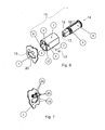
- Figure 6 illustrates another embodiment of a lock assembly comprising the lock cylinder 11 in an unassembled condition, which lock cylinder 11 is adapted for a lock housing 1 designed in accordance with figure 5 .
- the lock house 1 is illustrated in the same way as in figure 1 by part of the cover plate 1, which is provided with an opening 20 for the cylinder core 8.
- the opening 20 is also in this embodiment adapted to receive a portion of the cylinder house 3, and the opening 20 is therefore provided with a larger outer dimension than the end 19 of the cylinder core 8.
- the dimension of the opening corresponds to the dimension of an extending portion 12 of the cylinder house 3 and the end 19 of the cylinder core, so that the extending portion 12 of the cylinder house 3 as well as the end 19 of the cylinder core may be brought into the lock housing 1 during the assembling of the lock assembly.
- the extending portion 12 is non-cylindrical and the opening 20 is similarly non-cylindrical.
- the opening 20 has edges 15 for cooperation with the extending portion 12 to counteract rotation of the cylinder house 3 in relation to the lock house 1. In this way a lock having an improved strength against violence is provided.
- Figure 7 illustrates a portion view of a cover plate (1) and anchoring means 2 of the lock house 1 of figure 5 .
- Figure 7 illustrates the outer side of the lock house 1, intended to face the cylinder house 3 and being provided with the anchoring pins 2.
- the anchoring pins 2 are arranged above the opening 20 and show the edges 15 of the opening adapted for receiving the extending portion 12 of the cylinder house 3, and the first end 19 of the cylinder core 8.
- a cylinder lock and a method for assembling of a cylinder lock have been described with examples.
- the construction of the cylinder lock provides a simplified method comprising the insertion of anchoring means (2) into the lock cylinder (11), and whereby the lock house (1) is secured to the lock cylinder (11) in the axial direction by means of positioning a securing element (7) in the lock cylinder (11) to a position engaging the anchoring means (2).
Landscapes
- Engineering & Computer Science (AREA)
- Mechanical Engineering (AREA)
- Snaps, Bayonet Connections, Set Pins, And Snap Rings (AREA)
- Insertion Pins And Rivets (AREA)
Abstract
Description
- The invention relates to cylinder locks comprising a lock cylinder having an attachment for attaching to a lock housing, especially a lock cylinder wherein a cylinder core is arranged in a cylinder housing. The invention also relates to assembling of a lock cylinder and a housing of the lock.
- The invention relates to lock cylinders comprising a cylinder core arranged in a housing of the lock cylinder. Such a lock cylinder normally comprises locking pins in pin channels extending from housing to cylinder core. The locking pins prevent rotation of the cylinder core in relation to the cylinder housing. The locking pins are arranged to be effected by a key when entering into a key hole and further in a key channel through the cylinder core. With the correct key the locking pins are lifted so that the cylinder core can rotate inside the housing. The cylinder core does not move in the axial direction of the cylinder house when the key is inserted into the lock, instead they are kept mutually unmoving in the longitudinal direction also with the correct key inserted in the lock.
- In the Swedish patent
SE526189 W02005/049945 ) a locking device is shown that comprises a lock housing (10, 20 see abstract andfigure 4 ), and at the side of the housing a lock cylinder 40 is arranged comprising a cylinder house 41 and a cylinder core (plug 42) which is rotatably arranged in an opening 41a of the cylinder house. A mounting hole 22 in the lock house is adapted to receive an anchoring part 42c at the inner end of the cylinder plug. The movement of the cylinder core in the axial direction is prevented in a fixating position of the cylinder core when the anchoring part engages the housing of the lock. - It is illustrated further in
figure 6 that the outer envelope surface of the cylinder core (see especiallypage 7 line 4-22) is provided with a machined groove 42b traversing the axial direction. This groove runs a predetermined distance around the cylinder core and is arranged to cooperate with a latch pin 44, which during assembly is fixed into position in a hole 41b in the cylinder house. The latch pin 44 locks the movement of the inserted cylinder core in the axial direction, by means of the latch pin engaging the groove so that the axial movement of the core is prevented. An additional function of the latch pin is to limit the rotation of the cylinder core when a key is inserted in the lock (page 7, line 23-25). - An aim of the invention is to provide a locking device comprising a cylinder lock having a lock cylinder attached to a lock housing, which lock cylinder shows a cylinder core arranged in a cylinder house, which cylinder core is rotatably fastened in the cylinder house so that they are kept mutually unmovable in the axial direction of the cylinder core.
- An aim is to also provide a lock contributing to a comparatively efficient manufacturing and assembly.
- An aim is to be able to fasten the lock cylinder to the lock housing in a simple way, so that the lock cylinder can not move in the axial direction in relation to the lock housing.
- An aim is to be able to fasten the cylinder core in a simple way to the cylinder house, so that the cylinder core cannot move in its axial direction in relation to the cylinder house.
- The invention defines a lock device that is an assembly of a lock housing and a lock cylinder, which lock cylinder comprises a cylinder house and a cylinder core. The lock assembly comprises a lock housing and a lock cylinder, and the lock housing is provided with at least one anchoring means that extends out of the lock housing, the lock cylinder is provided with an anchoring hole, or anchoring holes, for the anchoring means. The lock cylinder is also provided with an assembling hole which is joined with the anchoring hole, the lock assembly further comprises a securing element, which is adapted for being arranged in the assembling hole and extend into the anchoring hole. The anchoring means and the securing element are formed to engage when the anchoring means are arranged in the anchoring hole and the securing element is arranged in the assembling hole, so that the lock housing is attached to the lock cylinder.
- The securing element is suitably adapted to prevent removal of the anchoring means from the anchoring holes. The anchoring means are preferably provided with head portions that make their width larger and the securing element is arranged between the head portions of the anchoring means and the lock housing so that disassembling is prevented.
- Preferably, the lock cylinder comprises a cylinder core and a cylinder house provided with a cylindrical space, wherein the cylinder core is adapted to be arranged inserted into the cylindrical space.
- In a preferred embodiment, the cylinder core is provided with a groove which provides a passage through the lock cylinder from the assembling hole when the cylinder core is arranged in the cylinder house. The groove in the cylinder core is intended to be positioned inside the assembling hole and the groove can in this way be reached from outside the lock cylinder through the assembling hole.
- In an embodiment, the securing element is adapted to cooperate with the groove of the cylinder core, when the cylinder core is positioned inserted in the hole of the lock housing in the intended use position. Hereby the securing element immobilizes the axial movement of the inserted cylinder core. When the assembling hole joins the cylindrical space, the securing element provides, apart from securing the lock cylinder to the lock house, also a fastening of the cylinder core to the cylinder house.
- An alternative to this double function is to use two separate securing elements, one for securing the lock housing to the lock cylinder, and another for securing the cylinder core in the cylinder house.
- In an embodiment, the groove is formed in the envelope surface of the cylinder core and extends one turn around the cylinder core. Such a groove in the core can be made by a turning machine.
- In an embodiment, the groove is formed in the envelope surface of the cylinder core and extends a fraction of a turn around the cylinder core, such as approximately half a turn. Accordingly the securing element provide a further function in that it in cooperation with the groove creates a limit to the rotation of the cylinder core, so that the turning of an inserted key is limited to only a portion of a turn, such as a quarter of a turn. Such a groove can for example be machine cut into the enveloping surface of the core by means of a milling machine.
- In an embodiment, a pin constitutes the securing element. This provides a simple construction and simple assembling. The pin is preferably provided with grooves for cooperation with an inside of the hole of the cylinder house, so that it is secured in the assembled position in the assembling hole.
- In a preferred embodiment of the anchoring means, the anchoring means comprises a body portion and a head portion, and the anchoring means is formed fixed to the lock housing to be inserted into the anchoring hole with the head section entering before the body section.
- The invention give suitable examples of embodiments, wherein the anchoring holes are arranged in the cylinder house and wherein the assembling hole extends from an outside of the cylinder house into the cylindrical space.
- In an embodiment, the assembling hole is a through hole and extends through the cylinder lock. This facilitates disassembling of the assembly, for example a securing element of pin shape can be pushed straight out through the hole.
- The invention also provides a method for assembling a lock assembly where a lock cylinder is secured to a lock housing, which lock housing comprises at least one anchoring means for anchoring the lock housing to the cylinder house. The method includes anchoring the lock cylinder to the lock housing so that the lock cylinder is secured to the lock housing in its axial direction. The method comprises insertion of the anchoring means into the lock cylinder, and that the securing of the lock housing, in the axial direction, to the lock cylinder includes insertion, into the lock cylinder, of a securing element reaching to the anchoring means.
- Preferably the insertion of the securing element is performed across the axial direction.
- An embodiment the insertion of the anchoring means of the lock housing into the anchoring holes of the cylinder house is performed in the axial direction.
- In a preferred embodiment the method includes insertion of the securing element, so that the securing element in its inserted position is located in a groove in a cylinder core arranged in the cylinder lock. Thereby also the cylinder core is secured in its axial direction.
- In a preferred embodiment the method of assembling is performed with a lock cylinder comprising a cylinder house provided with anchoring holes. The insertion of the anchoring means of the lock house into the lock cylinder is then performed by inserting the anchoring means into the anchoring holes provided in the cylinder house. This insertion is performed in the axial direction of the lock cylinder.
- The method preferably comprises that the cylinder core is inserted into the cylinder house in an axial direction, and that the cylinder core, the cylinder house and the lock house are secured to each other in the axial direction. This is preferably performed by inserting a securing element through the cylinder house to the cylinder core and the anchoring means. Hereby it is suitable to use a cylinder core provided with any of the previously mentioned grooves. By letting the securing element cooperate with both the anchoring means and the cylinder core, the securing of both the cylinder core to the cylinder house as well as the lock cylinder to the lock house be performed simultaneously, which contributes to a simple an rational manufacture.
- In the created assembly, the cylinder house and the cylinder core cooperate so that the cylinder core is rotatably mounted in a bearing, i.e. so that it can be rotated by an inserted key and be held axially in relation to the cylinder house, by means of the securing element being arranged in the assembling hole and extending at least partially past the cylinder core in or through the groove.
- A securing pin as securing element for keeping together both the lock house, the cylinder house and the cylinder core contributes to an especially simple construction and simple assembling of the included parts to a cylinder lock.
- The invention will now be described with fuller examples of embodiments with reference to the figures where constructional details are illustrated to facilitate carrying out the invention.
-
Figure 1 shows parts of a lock assembly comprising a cylinder lock in unassembled condition. -
Figure 2 shows a cross section of the cylinder core of an alternative embodiment. -
Figure 3 illustrates the lock assembly, with lock housing, cylinder house and cylinder core in an unassembled condition. -
Figure 4 illustrates a cross section of the lock assembly in an assembled condition. -
Figure 5 illustrates a lock house. -
Figure 6 illustrates a second embodiment of a lock assembly comprising a cylinder lock in an unassembled condition, in which a lock cylinder is adapted for a lock house designed in accordance withfigure 5 . -
Figure 7 illustrates a view of a portion of a cover plate and the anchoring means of the lock housing offigure 5 . - A first embodiment in
figure 1 illustrates a lock assembly in accordance with the invention. The lock assembly comprises alock housing 1, which is only partly illustrated by a cover plate infigure 1 , and alock cylinder 11. Thelock housing 1 is suitably provided with a mechanism for acting on a locking latch or locking bolt (figure 5 illustrates a lock housing with locking bolt 16) and is operatively connected to such a locking latch or bolt, which in turn is adapted for locking a door, such as a door of a locker or cabinet. - The cover plate arranged on the
lock housing 1 is provided with two anchoringpins 2 that are adapted to anchor thecylinder house 3 of thecylinder lock 11 to thelock housing 1. In an alternative embodiment the lock housing comprises only one anchoring means. The anchoring pins 2 are fixed in the cover plate / lock housing by means of, for example, heads 2c and securingly stamped in the lock housing, or can be designed as a molded part of the cover plate of the lock housing. Each anchoringpin 2 is made of acylindrical body 2a that extends essentially perpendicular out from ofcover plate 1 and is ended with ahead 2b that has a larger cross section than thebody 2a. The anchoring pins 2 are adapted to be inserted through a front piece or gable of acylinder house 3 for attaching the cover plate of thelock housing 1 to thecylinder house 3. The two anchoring pins are parallel and prevent, when they have been inserted in the anchoring holes, that thelock housing 1 andcylinder house 3 rotate in relation to each other. During assembly the anchoring pins cooperates with a securingelement 7, which is positioned engaging with thehead 2b, at the transition of the head towards thebody 2a, and cooperates in engagement with an underside of the head to hold the anchoring pins 2 and thereby the lock housing fixed to thecylinder house 3. Thelock house 1 is also provided with anopening 20 for acylinder core 8 of thecylinder lock 11. - The
cylinder house 3 comprises anchoringholes 4 for the anchoring pins 2, the anchoring holes 4 are provided in a gable that is intended to face thelock housing 1. During assembling of thelock housing 1 and thecylinder house 3, the anchoring pins 2 are inserted in the anchoring holes 4 and the securingelement 7 secures the anchoring pins 2 in the inserted position in the anchoring holes 4, so that the anchoring pins 2 are prevented from being removed out from the anchoring holes 4. - The cylinder house comprises an assembling
hole 5 in one side, which hole extends from the outer side of the cylinder house to the anchoring holes 4. The assemblinghole 5 is adapted for the insertion of the securing element that in cooperation with the anchoring pins 2 attach the lock house to the cylinder house. The securing element is formed like apin 7 and shall be arranged so that it blocks relative motion between the lock housing and the cylinder house. The blockingpin 7 is provided withsmall grooves 17 for being secured in the assemblinghole 5. - The
cylinder house 3 also provides acylindrical space 6 adapted for acylinder core 8. Thecylindrical space 6 extends in axial direction, from gable to gable, inside thecylinder house 3. - The
cylinder lock 11 of the lock assembly further comprises acylinder core 8 adapted to be arranged in thecylinder house 3, thecylinder core 8 is adapted for being inserted into thecylindrical space 6 through the front piece or gable of the cylinder house.Figure 1 illustrate the insertion of thecylinder core 8 in thecylinder house 3 through the opposite gable to the gable in which the anchoring holes 4 for the anchoring pins are provided. The invention allows nevertheless that the assembling is performed by inserting thecylinder core 8 into thecylinder house 3 through the same gable as the anchoring pins 2 are inserted into the anchoring holes 4. Thecylinder core 8 has acylindrical groove 9 in its enveloping surface, which can be created for example by means of machine milling or turning. Thegroove 9 in the outer surface is adapted to cooperate with the securingelement 7, so that thecylinder core 8 is held axially in thecylinder house 3. With the securingelement 7 arranged in thecylinder groove 9 in the enveloping surface of thecylinder core 8 thecylinder core 8 is rotatable supported in a bearing in thecylinder house 3. When the lock is assembled, thecylinder house 3 and thecylinder core 8 is brought together, with thecylinder core 8 inside thecylinder house 3, until thegroove 9 is situated in connection with the assemblinghole 5. During assembling, the anchoring pins 2 are brought in through the gable of the cylinder house so that thehead portions 2b of the anchoring pins pass the assemblinghole 5. After that, the blockingpin 7 is brought into the assemblinghole 5, to a securing position where the blockingpin 7 extends through the side wall of thecylinder house 3, in thegroove 9 and between thelock housing 1 and thehead 2b of the anchoring pins, so that thecylinder core 8 and thelock housing 1 is attached to the cylinder house during the insertion. At the same time, anend 19 of thecylinder core 8 is brought into the lock housing, which end 19 is designed to cooperate with a locking latch or locking bolt inside thelock housing 1. Theillustrated end 19 is non-cylindrical for easier cooperation with the locking mechanism in thelock housing 1, whereas the remaining sections of thecylinder core 8 are essentially cylindrical. - The
cylinder core 8 is further provided with akey channel 13, and the key is provided for insertion from thecylinder side 14 of the lock assembly, i.e. when the key is brought in the opposite direction of the direction in which the anchoring pins 2 of thelock housing 1 is inserted in the gable of thecylinder house 3. -
Figure 2 illustrates a cross section of thecylinder core 8 and an alternative embodiment wherein thegroove 9 in the enveloping surface allow a 90 degree rotation of the cylinder core, i.e. a blocking pin arranged in thegroove 10 limit the rotation to approximately 90 degrees. A vertically arrangedkey slot 13 is illustrated infigure 2 , so that having ahorizontal blocking pin 7 arranged above thekey slot 13, across the axial direction of thelock cylinder 11, allows the key to be rotated 90 degrees into a horizontal orientation. - Further to
figure 1 ,channels 17 in the upper part of thecylinder core 8 are also illustrated infigure 1 , which channels extends further in to thecylinder house 3 and are provided for lock or block pins. The lock pins may comprise more parts, such as lower and upper pins, known to be referred to as key and driver pins, and inside the pin channel springs are usually arranged for operating the lock pins in the direction towards their initial position, so that they are brought back when an inserted key is removed. Lock pin channels can also be arranged in the side surfaces of the core, but further details of the design of the blocking or locking pins and the pin channels are only outlined in general, since the invention is useful for cylinder locks having various types of locking pin arrangements. The illustratedcylinder core 8 is, thus, adapted for locking elements taking the form of locking pins. Alternatively, the cylinders having other locking elements may be used for the lock assembly, such as comprising locking discs or locking wafers as locking elements. The locking elements can be oriented sideways from the key channel. -
Figure 3 illustrates thelock cylinder 11 attached to thelock housing 1. Thelock cylinder 11 has an outwardly facing side, which side is provided with a key slot with a key channel (14 illustrates the direction of insertion for the key) in the cylinder core, and an opposite side of the cylinder lock is secured to thelock house 1. -
Figure 4 illustrates the cross section A-A offigure 3 . In this section, thekey channel 13 in the cylinder core is illustrated, andgroove 9 in the enveloping surface ofcylinder core 8. The blockingpin 7 is inserted in thecylinder house 3 and extends through thegroove 9 along thecylinder core 8 at its narrower area at thegroove 9. The blockingpin 7 also extends beyond the anchoring pins 2 at theirbody sections 2a, so that thehead sections 2b is stopped by the blockingpin 7, i.e. the blockingpin 7 is arranged between the insertion gable of the anchoring pins 2 and theheads 2b of the anchoring pins at theirnarrower section 2a. The blockingpin 7 is horizontally arranged, perpendicular to the length axis of the horizontally arrangedcylinder core 8. Thekey channel 13 extends in parallel with the length axis of thecylinder core 8 through thecylinder core 8. - During assembling of the
lock assembly cylinder core 8 is inserted in thecylinder house 3 and the anchoring means 2 of thelock house 1 is inserted into thecylinder house 3, where after the three parts;lock house 1,cylinder house 3 andcylinder core 8 are secured to each other by means of inserting alocking element 7 , such as a blocking pin, through thecylinder house 3 into cooperation with corresponding parts (9) for securing on thecylinder core 8 and the anchoring means 2. Thus, the cylinder core is inserted into a position where the assemblinggroove 9 is situated straight inside (within) theassembling hole 5. In a similar manner the anchoring pins 2 are inserted to a position where eachrespective body 2a is located straight inside the assembling hole, i.e. theheads 2b are inserted to a position beyond the assembling hole and a part of thecylinder core 8 is moved passed (beyond) theassembling hole 5. Theheads 2a of each respective anchoring pin and thegroove 9 in thecylinder core 8 are adapted in size so that the insertion of the blocking pin through the assembling hole is not obstructed; to the contrary, the hole forms an essentially unaffected channel through the cylinder house when the anchoring pins 2 and thecylinder core 8 have been positioned in the intended position. A part of thecore 8 and the anchoring pins (heads 2b) have in this situation passed beyond the assemblinghole 5, and these parts cooperate after the insertion of the blocking pin to prevent disassembling of the lock assembly. - The assembling
hole 5 is preferably made thoroughgoing, totally through thecylinder house 3 from one side to the other for facilitating a subsequent disassembly or service. During such a disassembly theblocking pin 7 may be pushed or knocked out off thecylinder house 3. -
Figure 5 illustrates thelock housing 1 of the lock assembly. Thelock housing 1 comprises anopening 20 for receiving oneend 19 of the cylinder core (8), which is adapted for cooperation with a lock mechanism in thelock housing 1, and in the assembled condition the cylinder core (8) is operatively connected to a locking bolt or latch 16, which is arranged at, and extends from, thelock housing 1. The anchoring pins 2 for the cylinder house are positioned close to theopening 20 for the cylinder core. -
Figure 6 illustrates another embodiment of a lock assembly comprising thelock cylinder 11 in an unassembled condition, which lockcylinder 11 is adapted for alock housing 1 designed in accordance withfigure 5 . Thelock house 1 is illustrated in the same way as infigure 1 by part of thecover plate 1, which is provided with anopening 20 for thecylinder core 8. Theopening 20 is also in this embodiment adapted to receive a portion of thecylinder house 3, and theopening 20 is therefore provided with a larger outer dimension than theend 19 of thecylinder core 8. The dimension of the opening corresponds to the dimension of an extendingportion 12 of thecylinder house 3 and theend 19 of the cylinder core, so that the extendingportion 12 of thecylinder house 3 as well as theend 19 of the cylinder core may be brought into thelock housing 1 during the assembling of the lock assembly. Further, the extendingportion 12 is non-cylindrical and theopening 20 is similarly non-cylindrical. Theopening 20 hasedges 15 for cooperation with the extendingportion 12 to counteract rotation of thecylinder house 3 in relation to thelock house 1. In this way a lock having an improved strength against violence is provided. -
Figure 7 illustrates a portion view of a cover plate (1) and anchoring means 2 of thelock house 1 offigure 5 .Figure 7 illustrates the outer side of thelock house 1, intended to face thecylinder house 3 and being provided with the anchoring pins 2. The anchoring pins 2 are arranged above theopening 20 and show theedges 15 of the opening adapted for receiving the extendingportion 12 of thecylinder house 3, and thefirst end 19 of thecylinder core 8. - A cylinder lock and a method for assembling of a cylinder lock have been described with examples. The construction of the cylinder lock provides a simplified method comprising the insertion of anchoring means (2) into the lock cylinder (11), and whereby the lock house (1) is secured to the lock cylinder (11) in the axial direction by means of positioning a securing element (7) in the lock cylinder (11) to a position engaging the anchoring means (2).
Claims (18)
- Lock assembly comprising a lock housing (1) and a lock cylinder (11), wherein the lock housing (1) is provided with at least one anchoring means (2) that extends out of the lock housing, the lock cylinder (11) is provided with at least one anchoring hole (4) for the anchoring means (2), the lock cylinder (11) is also provided with an assembling hole (5) which is joining the anchoring hole (4),
the lock assembly further comprising a securing element (7) that is adapted for being arranged in the assembling hole (5) and extend into the anchoring hole,
the anchoring element (2) and the securing element (7) are formed to engage when the anchoring means (2) are arranged in the anchoring hole (4) and the securing element (7) is arranged in the assembling hole (5), so that the lock housing is attached to the lock cylinder. - Lock assembly according to claim 1, which lock cylinder (11) comprises a cylinder core (8) and a cylinder house (3) provided with a cylindrical space (6), wherein the cylinder core (8) is adapted to be arranged inserted into the cylindrical space.
- Lock assembly according to claim 2, wherein the cylinder core is provided with a groove (9) which provides a passage through the lock cylinder from the assembling hole (5) when the cylinder core is arranged in the cylinder house (3).
- Lock assembly according to any of claims 2-3, wherein the securing element (7) cooperates with the groove (9) of the cylinder core, when the cylinder core (8) is arranged inserted in the lock housing (1) and the securing element (7) is arranged in the assembling hole (5) of the cylinder house (3).
- Lock assembly according to any of claims 3-4, wherein the groove (9) is formed in the envelope surface of the cylinder core (8) and extends around the circumference of the cylinder core (8).
- Lock assembly according to any of claims 3-4, wherein the groove (9) is formed in the envelope surface of the cylinder core (8) and extends around a fraction of the circumference of the cylinder core (8), such as approximately half a turn.
- Lock assembly according to any of claims 2-6, wherein the lock housing (1) is formed with an opening (20) adapted to receive a protruding section (12) of the cylinder house (3).
- Lock assembly according to claim 7, which opening (20) is surrounded by edges (15) formed to, in cooperation with the protruding section (12), prevent mutual rotation of the lock housing (1) in relation to the cylinder house (3).
- Lock assembly according to any of the previous claims, wherein a pin constitutes the securing element (7).
- Lock assembly according to claim 9, wherein the pin (7) is provided with small grooves (17) for cooperation with an inside of the assembling hole (5) of the cylinder house (3).
- Lock assembly according to any of the previous claims, wherein the anchoring means (2) comprises a body section (2a) and a head section (2b), and the anchoring means (2) is formed to be inserted into the anchoring hole (4) with the head section entering before the body section.
- Lock assembly according to any of the previous claims, wherein the anchoring hole (4) is arranged in the cylinder house (3).
- Lock assembly according to any of the previous claims, wherein the assembling hole (5) extends from an outside of the cylinder house (3) into the cylindrical space (6).
- Lock assembly according to any of the previous claims, wherein the assembling hole (5) is a through hole and extends through the cylinder lock (3).
- Method of assembling a lock assembly where a lock cylinder (11) is secured to a lock housing (1), which lock housing (1) comprises at least one anchoring means (2) for anchoring the lock housing (1) to the lock cylinder (11), the method includes anchoring the lock cylinder (11) to the housing (1) so that the lock cylinder (11) is secured to the housing (1) in its axial direction, characterized in
inserting the anchoring means (2) into the lock cylinder (11),
and wherein the securing of the lock housing (1) to the lock cylinder (11) in the axial direction includes positioning a securing element (7) in the lock cylinder (11) to a position engaging the anchoring means (2). - Method according to claim 15, wherein the securing element (7), inserted into position, is located in a groove (9) in a cylinder core (8) arranged in the cylinder lock.
- Method according to any of claims 15 or 16, which lock cylinder (11), comprises a cylinder house (3) and wherein the insertion of the anchoring means (2) of the lock house (1) into the lock cylinder is performed into the anchoring hole (4) provided in the cylinder house (3).
- Method according to claim 17, which inserting is performed in the axial direction of the lock cylinder (11).
Applications Claiming Priority (1)
| Application Number | Priority Date | Filing Date | Title |
|---|---|---|---|
| SE0950685A SE534121C2 (en) | 2009-09-18 | 2009-09-18 | Lock assemblies and method for assembling lock assemblies |
Publications (2)
| Publication Number | Publication Date |
|---|---|
| EP2299038A2 true EP2299038A2 (en) | 2011-03-23 |
| EP2299038A3 EP2299038A3 (en) | 2017-05-24 |
Family
ID=43500256
Family Applications (1)
| Application Number | Title | Priority Date | Filing Date |
|---|---|---|---|
| EP10177157.4A Withdrawn EP2299038A3 (en) | 2009-09-18 | 2010-09-16 | Lock assembly and method of assembling the lock |
Country Status (2)
| Country | Link |
|---|---|
| EP (1) | EP2299038A3 (en) |
| SE (1) | SE534121C2 (en) |
Citations (1)
| Publication number | Priority date | Publication date | Assignee | Title |
|---|---|---|---|---|
| WO2005049945A1 (en) | 2003-11-18 | 2005-06-02 | Assa Ab | Lock device, lock cylinder and method of mounting a lock cylinder |
Family Cites Families (2)
| Publication number | Priority date | Publication date | Assignee | Title |
|---|---|---|---|---|
| SE9103385L (en) * | 1991-11-15 | 1993-05-16 | Assa Ab | CYLINDERLAAS |
| US5970760A (en) * | 1999-01-11 | 1999-10-26 | Shen; Mu-Lin | Lock core-changeable type auxiliary lock with improved pull-resistant structure |
-
2009
- 2009-09-18 SE SE0950685A patent/SE534121C2/en not_active IP Right Cessation
-
2010
- 2010-09-16 EP EP10177157.4A patent/EP2299038A3/en not_active Withdrawn
Patent Citations (2)
| Publication number | Priority date | Publication date | Assignee | Title |
|---|---|---|---|---|
| WO2005049945A1 (en) | 2003-11-18 | 2005-06-02 | Assa Ab | Lock device, lock cylinder and method of mounting a lock cylinder |
| SE526189C2 (en) | 2003-11-18 | 2005-07-26 | Assa Ab | Locking device, way of mounting a lock cylinder on a lock housing and lock cylinder |
Also Published As
| Publication number | Publication date |
|---|---|
| SE0950685A1 (en) | 2011-03-19 |
| SE534121C2 (en) | 2011-05-03 |
| EP2299038A3 (en) | 2017-05-24 |
Similar Documents
| Publication | Publication Date | Title |
|---|---|---|
| US5987939A (en) | Padlock for use with steel grilles | |
| US6578396B2 (en) | Removable cylindrical lock core | |
| US20050011239A1 (en) | Convertible mortise/rim cylinder lock assembly with removable core | |
| US20090049875A1 (en) | Lock | |
| US6382006B1 (en) | Removable cylindrical lock core | |
| CA2801538C (en) | Lock assembly with an interchangeable lock core | |
| EP0291220A1 (en) | Coupling mechanism for double cylinder locks | |
| US4938039A (en) | Actuating mechanism for padlock | |
| CN103874816A (en) | Key with fixed key pins protruding from key cut surface | |
| US8485006B2 (en) | Disc tumbler cylinder lock and key combination | |
| CN101189403B (en) | Electromechanical lock device | |
| ES2985926T3 (en) | Profiled cylinder | |
| US20030136164A1 (en) | Lock device with removable core | |
| US7647798B1 (en) | Lock having variably-spaced side pins | |
| US7895865B2 (en) | Cylinder lock assembly with a tailpiece rotationally coupled to the cylinder plug | |
| US9951544B2 (en) | Cylinder lock | |
| US7523971B2 (en) | Spindle assembly with captive spring for use in a door handle assembly | |
| US5551263A (en) | Lock with dead bolt camming action on 90 degree lock cylinder rotation | |
| US20020149211A1 (en) | Door lock assembly having escutcheon with removable posts | |
| CA2539060A1 (en) | Spindle assembly for use in a door handle assembly | |
| EP2530224A2 (en) | Anti-tamper lock | |
| AU2002301313B2 (en) | Padlocks | |
| EP2278099A1 (en) | A cylinder lock | |
| US20050155398A1 (en) | Assembling structure for a door lock | |
| ES2341564T3 (en) | HARDWARE FOR DOORS, WINDOWS OR SIMILAR. |
Legal Events
| Date | Code | Title | Description |
|---|---|---|---|
| PUAI | Public reference made under article 153(3) epc to a published international application that has entered the european phase |
Free format text: ORIGINAL CODE: 0009012 |
|
| AK | Designated contracting states |
Kind code of ref document: A2 Designated state(s): AL AT BE BG CH CY CZ DE DK EE ES FI FR GB GR HR HU IE IS IT LI LT LU LV MC MK MT NL NO PL PT RO SE SI SK SM TR |
|
| AX | Request for extension of the european patent |
Extension state: BA ME RS |
|
| PUAL | Search report despatched |
Free format text: ORIGINAL CODE: 0009013 |
|
| AK | Designated contracting states |
Kind code of ref document: A3 Designated state(s): AL AT BE BG CH CY CZ DE DK EE ES FI FR GB GR HR HU IE IS IT LI LT LU LV MC MK MT NL NO PL PT RO SE SI SK SM TR |
|
| AX | Request for extension of the european patent |
Extension state: BA ME RS |
|
| RIC1 | Information provided on ipc code assigned before grant |
Ipc: E05B 9/08 20060101AFI20170418BHEP |
|
| STAA | Information on the status of an ep patent application or granted ep patent |
Free format text: STATUS: THE APPLICATION IS DEEMED TO BE WITHDRAWN |
|
| 18D | Application deemed to be withdrawn |
Effective date: 20171125 |