EP2298646A2 - System and method for rejecting heat from equipment via endothermic isomerization - Google Patents
System and method for rejecting heat from equipment via endothermic isomerization Download PDFInfo
- Publication number
- EP2298646A2 EP2298646A2 EP10177204A EP10177204A EP2298646A2 EP 2298646 A2 EP2298646 A2 EP 2298646A2 EP 10177204 A EP10177204 A EP 10177204A EP 10177204 A EP10177204 A EP 10177204A EP 2298646 A2 EP2298646 A2 EP 2298646A2
- Authority
- EP
- European Patent Office
- Prior art keywords
- compound
- heat
- heat exchanger
- isomerization
- isomerisation
- Prior art date
- Legal status (The legal status is an assumption and is not a legal conclusion. Google has not performed a legal analysis and makes no representation as to the accuracy of the status listed.)
- Withdrawn
Links
- 238000006317 isomerization reaction Methods 0.000 title claims abstract description 61
- 238000000034 method Methods 0.000 title claims abstract description 35
- 150000001875 compounds Chemical class 0.000 claims abstract description 55
- 239000012530 fluid Substances 0.000 claims abstract description 37
- 230000003197 catalytic effect Effects 0.000 claims abstract description 20
- 238000004891 communication Methods 0.000 claims abstract description 12
- VLKZOEOYAKHREP-UHFFFAOYSA-N n-Hexane Chemical compound CCCCCC VLKZOEOYAKHREP-UHFFFAOYSA-N 0.000 claims description 76
- HNRMPXKDFBEGFZ-UHFFFAOYSA-N 2,2-dimethylbutane Chemical compound CCC(C)(C)C HNRMPXKDFBEGFZ-UHFFFAOYSA-N 0.000 claims description 28
- 239000003054 catalyst Substances 0.000 claims description 12
- OFBQJSOFQDEBGM-UHFFFAOYSA-N Pentane Chemical compound CCCCC OFBQJSOFQDEBGM-UHFFFAOYSA-N 0.000 claims description 9
- MCMNRKCIXSYSNV-UHFFFAOYSA-N Zirconium dioxide Chemical class O=[Zr]=O MCMNRKCIXSYSNV-UHFFFAOYSA-N 0.000 claims description 7
- IMNFDUFMRHMDMM-UHFFFAOYSA-N N-Heptane Chemical compound CCCCCCC IMNFDUFMRHMDMM-UHFFFAOYSA-N 0.000 claims description 6
- VSCWAEJMTAWNJL-UHFFFAOYSA-K aluminium trichloride Chemical compound Cl[Al](Cl)Cl VSCWAEJMTAWNJL-UHFFFAOYSA-K 0.000 claims description 4
- 239000002253 acid Substances 0.000 claims description 3
- 239000001273 butane Substances 0.000 claims description 3
- IJDNQMDRQITEOD-UHFFFAOYSA-N n-butane Chemical compound CCCC IJDNQMDRQITEOD-UHFFFAOYSA-N 0.000 claims description 3
- TVMXDCGIABBOFY-UHFFFAOYSA-N octane Chemical compound CCCCCCCC TVMXDCGIABBOFY-UHFFFAOYSA-N 0.000 claims description 3
- 239000000446 fuel Substances 0.000 description 17
- 239000000203 mixture Substances 0.000 description 17
- ZFFMLCVRJBZUDZ-UHFFFAOYSA-N 2,3-dimethylbutane Chemical compound CC(C)C(C)C ZFFMLCVRJBZUDZ-UHFFFAOYSA-N 0.000 description 12
- AFABGHUZZDYHJO-UHFFFAOYSA-N 2-Methylpentane Chemical compound CCCC(C)C AFABGHUZZDYHJO-UHFFFAOYSA-N 0.000 description 8
- PFEOZHBOMNWTJB-UHFFFAOYSA-N 3-methylpentane Chemical compound CCC(C)CC PFEOZHBOMNWTJB-UHFFFAOYSA-N 0.000 description 8
- 230000015572 biosynthetic process Effects 0.000 description 8
- 230000008901 benefit Effects 0.000 description 5
- 238000006243 chemical reaction Methods 0.000 description 3
- 238000012986 modification Methods 0.000 description 3
- 230000004048 modification Effects 0.000 description 3
- 238000012546 transfer Methods 0.000 description 3
- 230000008016 vaporization Effects 0.000 description 3
- 238000013459 approach Methods 0.000 description 2
- 230000007423 decrease Effects 0.000 description 2
- 238000011161 development Methods 0.000 description 2
- 238000010438 heat treatment Methods 0.000 description 2
- 238000009834 vaporization Methods 0.000 description 2
- 229910021630 Antimony pentafluoride Inorganic materials 0.000 description 1
- 238000010276 construction Methods 0.000 description 1
- 239000002826 coolant Substances 0.000 description 1
- 238000013461 design Methods 0.000 description 1
- 230000000694 effects Effects 0.000 description 1
- -1 i.e. Chemical compound 0.000 description 1
- 230000003116 impacting effect Effects 0.000 description 1
- 239000007788 liquid Substances 0.000 description 1
- SYSQUGFVNFXIIT-UHFFFAOYSA-N n-[4-(1,3-benzoxazol-2-yl)phenyl]-4-nitrobenzenesulfonamide Chemical class C1=CC([N+](=O)[O-])=CC=C1S(=O)(=O)NC1=CC=C(C=2OC3=CC=CC=C3N=2)C=C1 SYSQUGFVNFXIIT-UHFFFAOYSA-N 0.000 description 1
- 239000000376 reactant Substances 0.000 description 1
- 238000000926 separation method Methods 0.000 description 1
Images

Classifications
-
- B—PERFORMING OPERATIONS; TRANSPORTING
- B64—AIRCRAFT; AVIATION; COSMONAUTICS
- B64D—EQUIPMENT FOR FITTING IN OR TO AIRCRAFT; FLIGHT SUITS; PARACHUTES; ARRANGEMENT OR MOUNTING OF POWER PLANTS OR PROPULSION TRANSMISSIONS IN AIRCRAFT
- B64D13/00—Arrangements or adaptations of air-treatment apparatus for aircraft crew or passengers, or freight space
-
- B—PERFORMING OPERATIONS; TRANSPORTING
- B64—AIRCRAFT; AVIATION; COSMONAUTICS
- B64D—EQUIPMENT FOR FITTING IN OR TO AIRCRAFT; FLIGHT SUITS; PARACHUTES; ARRANGEMENT OR MOUNTING OF POWER PLANTS OR PROPULSION TRANSMISSIONS IN AIRCRAFT
- B64D37/00—Arrangements in connection with fuel supply for power plant
- B64D37/34—Conditioning fuel, e.g. heating
-
- B—PERFORMING OPERATIONS; TRANSPORTING
- B01—PHYSICAL OR CHEMICAL PROCESSES OR APPARATUS IN GENERAL
- B01J—CHEMICAL OR PHYSICAL PROCESSES, e.g. CATALYSIS OR COLLOID CHEMISTRY; THEIR RELEVANT APPARATUS
- B01J8/00—Chemical or physical processes in general, conducted in the presence of fluids and solid particles; Apparatus for such processes
- B01J8/02—Chemical or physical processes in general, conducted in the presence of fluids and solid particles; Apparatus for such processes with stationary particles, e.g. in fixed beds
- B01J8/0285—Heating or cooling the reactor
-
- B—PERFORMING OPERATIONS; TRANSPORTING
- B64—AIRCRAFT; AVIATION; COSMONAUTICS
- B64D—EQUIPMENT FOR FITTING IN OR TO AIRCRAFT; FLIGHT SUITS; PARACHUTES; ARRANGEMENT OR MOUNTING OF POWER PLANTS OR PROPULSION TRANSMISSIONS IN AIRCRAFT
- B64D33/00—Arrangement in aircraft of power plant parts or auxiliaries not otherwise provided for
- B64D33/08—Arrangement in aircraft of power plant parts or auxiliaries not otherwise provided for of power plant cooling systems
-
- C—CHEMISTRY; METALLURGY
- C07—ORGANIC CHEMISTRY
- C07C—ACYCLIC OR CARBOCYCLIC COMPOUNDS
- C07C5/00—Preparation of hydrocarbons from hydrocarbons containing the same number of carbon atoms
- C07C5/22—Preparation of hydrocarbons from hydrocarbons containing the same number of carbon atoms by isomerisation
- C07C5/27—Rearrangement of carbon atoms in the hydrocarbon skeleton
- C07C5/2702—Catalytic processes not covered by C07C5/2732 - C07C5/31; Catalytic processes covered by both C07C5/2732 and C07C5/277 simultaneously
- C07C5/2705—Catalytic processes not covered by C07C5/2732 - C07C5/31; Catalytic processes covered by both C07C5/2732 and C07C5/277 simultaneously with metal oxides
-
- C—CHEMISTRY; METALLURGY
- C07—ORGANIC CHEMISTRY
- C07C—ACYCLIC OR CARBOCYCLIC COMPOUNDS
- C07C5/00—Preparation of hydrocarbons from hydrocarbons containing the same number of carbon atoms
- C07C5/22—Preparation of hydrocarbons from hydrocarbons containing the same number of carbon atoms by isomerisation
- C07C5/27—Rearrangement of carbon atoms in the hydrocarbon skeleton
- C07C5/2702—Catalytic processes not covered by C07C5/2732 - C07C5/31; Catalytic processes covered by both C07C5/2732 and C07C5/277 simultaneously
- C07C5/271—Catalytic processes not covered by C07C5/2732 - C07C5/31; Catalytic processes covered by both C07C5/2732 and C07C5/277 simultaneously with inorganic acids; with salts or anhydrides of acids
- C07C5/2718—Acids of halogen; Salts thereof; complexes thereof with organic compounds
- C07C5/2721—Metal halides; Complexes thereof with organic compounds
-
- F—MECHANICAL ENGINEERING; LIGHTING; HEATING; WEAPONS; BLASTING
- F02—COMBUSTION ENGINES; HOT-GAS OR COMBUSTION-PRODUCT ENGINE PLANTS
- F02C—GAS-TURBINE PLANTS; AIR INTAKES FOR JET-PROPULSION PLANTS; CONTROLLING FUEL SUPPLY IN AIR-BREATHING JET-PROPULSION PLANTS
- F02C7/00—Features, components parts, details or accessories, not provided for in, or of interest apart form groups F02C1/00 - F02C6/00; Air intakes for jet-propulsion plants
- F02C7/12—Cooling of plants
-
- F—MECHANICAL ENGINEERING; LIGHTING; HEATING; WEAPONS; BLASTING
- F28—HEAT EXCHANGE IN GENERAL
- F28D—HEAT-EXCHANGE APPARATUS, NOT PROVIDED FOR IN ANOTHER SUBCLASS, IN WHICH THE HEAT-EXCHANGE MEDIA DO NOT COME INTO DIRECT CONTACT
- F28D7/00—Heat-exchange apparatus having stationary tubular conduit assemblies for both heat-exchange media, the media being in contact with different sides of a conduit wall
- F28D7/16—Heat-exchange apparatus having stationary tubular conduit assemblies for both heat-exchange media, the media being in contact with different sides of a conduit wall the conduits being arranged in parallel spaced relation
- F28D7/1607—Heat-exchange apparatus having stationary tubular conduit assemblies for both heat-exchange media, the media being in contact with different sides of a conduit wall the conduits being arranged in parallel spaced relation with particular pattern of flow of the heat exchange media, e.g. change of flow direction
-
- B—PERFORMING OPERATIONS; TRANSPORTING
- B01—PHYSICAL OR CHEMICAL PROCESSES OR APPARATUS IN GENERAL
- B01J—CHEMICAL OR PHYSICAL PROCESSES, e.g. CATALYSIS OR COLLOID CHEMISTRY; THEIR RELEVANT APPARATUS
- B01J2208/00—Processes carried out in the presence of solid particles; Reactors therefor
- B01J2208/00008—Controlling the process
- B01J2208/00017—Controlling the temperature
- B01J2208/00106—Controlling the temperature by indirect heat exchange
- B01J2208/00115—Controlling the temperature by indirect heat exchange with heat exchange elements inside the bed of solid particles
- B01J2208/00132—Tubes
-
- B—PERFORMING OPERATIONS; TRANSPORTING
- B01—PHYSICAL OR CHEMICAL PROCESSES OR APPARATUS IN GENERAL
- B01J—CHEMICAL OR PHYSICAL PROCESSES, e.g. CATALYSIS OR COLLOID CHEMISTRY; THEIR RELEVANT APPARATUS
- B01J2208/00—Processes carried out in the presence of solid particles; Reactors therefor
- B01J2208/06—Details of tube reactors containing solid particles
- B01J2208/065—Heating or cooling the reactor
-
- B—PERFORMING OPERATIONS; TRANSPORTING
- B64—AIRCRAFT; AVIATION; COSMONAUTICS
- B64D—EQUIPMENT FOR FITTING IN OR TO AIRCRAFT; FLIGHT SUITS; PARACHUTES; ARRANGEMENT OR MOUNTING OF POWER PLANTS OR PROPULSION TRANSMISSIONS IN AIRCRAFT
- B64D13/00—Arrangements or adaptations of air-treatment apparatus for aircraft crew or passengers, or freight space
- B64D13/06—Arrangements or adaptations of air-treatment apparatus for aircraft crew or passengers, or freight space the air being conditioned
- B64D2013/0603—Environmental Control Systems
- B64D2013/0614—Environmental Control Systems with subsystems for cooling avionics
-
- B—PERFORMING OPERATIONS; TRANSPORTING
- B64—AIRCRAFT; AVIATION; COSMONAUTICS
- B64D—EQUIPMENT FOR FITTING IN OR TO AIRCRAFT; FLIGHT SUITS; PARACHUTES; ARRANGEMENT OR MOUNTING OF POWER PLANTS OR PROPULSION TRANSMISSIONS IN AIRCRAFT
- B64D13/00—Arrangements or adaptations of air-treatment apparatus for aircraft crew or passengers, or freight space
- B64D13/06—Arrangements or adaptations of air-treatment apparatus for aircraft crew or passengers, or freight space the air being conditioned
- B64D2013/0603—Environmental Control Systems
- B64D2013/0633—Environmental Control Systems including chemical reaction-based thermal management systems
-
- C—CHEMISTRY; METALLURGY
- C07—ORGANIC CHEMISTRY
- C07C—ACYCLIC OR CARBOCYCLIC COMPOUNDS
- C07C2521/00—Catalysts comprising the elements, oxides or hydroxides of magnesium, boron, aluminium, carbon, silicon, titanium, zirconium or hafnium
- C07C2521/06—Silicon, titanium, zirconium or hafnium; Oxides or hydroxides thereof
-
- C—CHEMISTRY; METALLURGY
- C07—ORGANIC CHEMISTRY
- C07C—ACYCLIC OR CARBOCYCLIC COMPOUNDS
- C07C2527/00—Catalysts comprising the elements or compounds of halogens, sulfur, selenium, tellurium, phosphorus or nitrogen; Catalysts comprising carbon compounds
- C07C2527/06—Halogens; Compounds thereof
- C07C2527/125—Compounds comprising a halogen and scandium, yttrium, aluminium, gallium, indium or thallium
- C07C2527/126—Aluminium chloride
-
- C—CHEMISTRY; METALLURGY
- C07—ORGANIC CHEMISTRY
- C07C—ACYCLIC OR CARBOCYCLIC COMPOUNDS
- C07C2527/00—Catalysts comprising the elements or compounds of halogens, sulfur, selenium, tellurium, phosphorus or nitrogen; Catalysts comprising carbon compounds
- C07C2527/06—Halogens; Compounds thereof
- C07C2527/133—Compounds comprising a halogen and vanadium, niobium, tantalium, antimonium or bismuth
-
- F—MECHANICAL ENGINEERING; LIGHTING; HEATING; WEAPONS; BLASTING
- F28—HEAT EXCHANGE IN GENERAL
- F28D—HEAT-EXCHANGE APPARATUS, NOT PROVIDED FOR IN ANOTHER SUBCLASS, IN WHICH THE HEAT-EXCHANGE MEDIA DO NOT COME INTO DIRECT CONTACT
- F28D21/00—Heat-exchange apparatus not covered by any of the groups F28D1/00 - F28D20/00
-
- F—MECHANICAL ENGINEERING; LIGHTING; HEATING; WEAPONS; BLASTING
- F28—HEAT EXCHANGE IN GENERAL
- F28F—DETAILS OF HEAT-EXCHANGE AND HEAT-TRANSFER APPARATUS, OF GENERAL APPLICATION
- F28F13/00—Arrangements for modifying heat-transfer, e.g. increasing, decreasing
- F28F13/003—Arrangements for modifying heat-transfer, e.g. increasing, decreasing by using permeable mass, perforated or porous materials
Definitions
- the present invention relates to heat sinks.
- the present invention relates to heat sinks for mobile implementations, such as vehicles.
- Equipment in vehicles such as airborne vehicles, land-based vehicles, space-based vehicles, and other such mobile equipment often generate heat that must be dissipated or rejected.
- heat produced by an automobile engine is rejected via coolant flowing through the automobile's radiator.
- heat is often rejected via the aircraft's skin to the air flowing over the skin.
- rejecting heat is more difficult.
- air impacting onto a high-speed aircraft often imparts heat into the aircraft's skin due to friction, instead of removing heat from the skin. If rejecting heat from such equipment is difficult or impossible, the equipment will continue to undesirably increase in temperature so long as heat is being generated within the equipment.
- Figure 1 is a graphical representation of an illustrative embodiment of a system for rejecting heat from heat-generating equipment
- Figures 2A-2D depict structural representations of chemical reactions occurring in the isomerization of hexane
- Figure 3 is a chart depicting exemplary concentrations of the isomers of hexane at various temperatures
- Figure 4 is a chart depicting exemplary equilibrium heat sink capacity for hexane isomerization and heat sink capacity for baseline Jet A fuel heating at various temperatures;
- Figure 5 is a chart depicting exemplary heat sink capacities for various residence times of hexane isomerization at 60°C and at 150°C using sulfated zirconia as a catalyst and at a pressure of about 1.5 megapascals in a constantly stirred reactor, as well as exemplary heat sink capacities of Jet A fuel when the temperature thereof is increased to 60°C and to 150°C;
- Figure 6 is a chart depicting exemplary reactor volumes at various temperatures required to achieve 23 kilowatts of power sink at an operating pressure of 1.5 megapascals, assuming a 60 second residence time;
- Figure 7 is a chart depicting heat sink capacity for 2,2-dimethylbutane isomerization with vaporization and baseline Jet A fuel heating at various temperatures;
- Figure 8 is a stylized, graphical representation of an illustrative embodiment of a system for rejecting heat generated by heat-generating equipment of a vehicle.
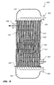
- Figure 9 is a cross-sectional view of an illustrative embodiment of a catalytic heat exchanger of the system shown in Figure 8 .
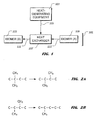
- FIG. 1 provides a graphical representation of an illustrative embodiment of a system 101 for rejecting heat from a heat-generating equipment 103.
- a process fluid represented by an arrow 105
- a compound capable of endothermically isomerizing i.e., "isomer (A)" 109, is inputted to heat exchanger 107, as indicated by an arrow 111.
- Heat from process fluid 105 is transferred to isomer (A) 109 within heat exchanger 107, thus endothermically isomerizing isomer (A) 109 to "isomer (B)" 113, which is outputted from heat exchanger 107, as indicated by an arrow 115.
- the present invention contemplates many compounds that exhibit isomerism.
- An isomeric compound exists in two or more structural forms; however, the two or more structural forms have the same molecular formula.
- each isomer has a given enthalpy of formation, as a function of temperature and pressure. If, for example, the temperature of the isomer of the compound having the lowest enthalpy of formation is increased, heat will be absorbed by the isomer and at least a portion of the isomer will change form to an isomer of the compound having a higher enthalpy of formation.
- an isomeric compound will exist at an equilibrium mixture of the one or more isomers of the compound.
- the mixture contains an isomer of the compound that exhibits a lower enthalpy of formation than the equilibrium mixture of the isomers and the temperature of the mixture is increased, the lower enthalpy of formation-isomer will absorb heat and change form to an isomer of the compound having a higher enthalpy of formation.
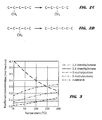
- the isomeric compound is hexane. All isomeric forms of hexane exhibit the molecular formula C 6 H 14 . However, hexane exists as five structurally different isomers: 2,2-dimethylbutane, 2,3-dimethylbutane, 2-methylpentane, 3-methylpentane, and n-hexane, i.e., normal hexane.
- Figures 2A-2D depict the structural changes resulting from the isomerization of 2,2-dimethylbutane to 2,3-dimethylbutane ( Figure 2A ); 2,3-dimethylbutane to 2-methylpentane ( Figure 2B ); 2-methylpentane to 3-methylpentane ( Figure 2C ); and 3-methylpentane to n-hexane ( Figure 2D ).
- the isomers of hexane have the following enthalpies of formation at a temperature of 25°C and at a pressure of one atmosphere: Isomer Enthalpy of formation (kilojoules per mole) n-hexane -167.3 3-methylpentane -172.4 2-methylpentane -174.9 2,3-dimethylbutane -177.2 2,2-dinnethylbutane -185.0
- 2,2-dimethylbutane exhibits the lowest heat of formation of the isomers of hexane. Isomerization of 2,2-dimethylbutane to any of the other four isomers of hexane is endothermic.
- Figure 3 depicts exemplary concentrations of the isomers of hexane at various temperatures.
- the equilibrium mixture contains approximately 53 molecular percent 2,2-dimethylbutane.
- the equilibrium mixture contains approximately 40 molecular percent 2,2-dimethylbutane.
- the fraction of 2,2-dimethylbutane in the equilibrium mixture decreases and the fraction of n-hexane in the equilibrium mixture increases.
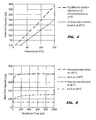
- both the heat of isomerization and the heat required to raise the temperature of the mixture can be sunk into the mixture.
- raising the temperature of the mixture from 25°C to 100°C can sink about 245 joules of heat per gram of mixture.
- raising the temperature of "Jet A" fuel from 25°C to 100°C sinks only about 150 joules of heat per gram of Jet A fuel.
- the present invention contemplates compounds other than hexane as isomerization compounds.
- octane C 8 H 18
- heptane C 7 H 16
- pentane C 5 H 12
- butane C 4 H 10
- isomerization compounds may, in certain embodiments, be used as isomerization compounds.
- the change from a more endothermic mixture to the equilibrium mixture only provides heat sink capacity, not the rate at which the mixture can sink heat.
- the present invention contemplates the use of a catalyst to increase the isomerization rate.
- One particular catalyst contemplated by the present invention is sulfated zirconia.
- Figure 5 depicts exemplary heat sink capacities for various residence times of hexane isomerization at 60°C and at 150°C using sulfated zirconia as a catalyst and at a pressure of about 1.5 megapascals in a constantly stirred reactor, as well as exemplary heat sink capacities of Jet A fuel when the temperature thereof is increased to 60°C and to 150°C.
- exemplary heat sink capacities of Jet A fuel when the temperature thereof is increased to 60°C and to 150°C.
- kinetics are slower at lower temperatures, longer times are required at lower temperatures to achieve the equilibrium state. For example, at 60°C, about five minutes are required to approach the equilibrium state, whereas at 150°C only about two minutes are required to approach the equilibrium state.
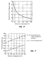
- the volume of the reactor required to sink a given amount of power decreases, because the residence time drops.
- Figure 6 depicts exemplary reactor volumes at various temperatures required to achieve 23 kilowatts of power sink at an operating pressure of 1.5 megapascals, assuming a 60 second residence time.
- a reactor volume of about 58 gallons would be required to sink 23 kilowatts of power at an operating temperature of 80°C and an operating pressure of 1.5 megapascals, assuming a 60 second residence time.
- a reactor volume of only about 20 gallons would be required to sink 23 kilowatts of power at an operating pressure of 1.5 megapascals, assuming a 60 second residence time.
- catalysts other than sulfated zirconia are contemplated by the present invention.
- aluminum trichloride (AlCl 3 ), fluoroantimonic acid (HF-SbF 5 ), or the like may be used as catalysts and, in particular, may be used in systems utilizing hexane isomerization.
- the latent heat of vaporization can be a significant heat sink.
- the products of isomerization vaporize at temperatures within a range of about 50°C to about 69°C at atmospheric pressure. Vaporizing the products of isomerization can provide, for example, an additional 300 joules per gram of heat sink capacity, as shown in Figure 7 .
- FIG. 8 depicts an illustrative embodiment of a system 801 for rejecting heat generated by heat-generating equipment 803 of a vehicle 805.
- vehicle 805 is an aircraft.
- System 801 may be applied to many various heat-generating equipments 803.
- heat-generating equipment 803 is an engine 807 for propelling vehicle 803; however, the scope of the present invention is not so limited.
- System 801 comprises a reservoir of an isomerization compound 809 capable of endothermic isomerization, such as the isomerization compounds discussed herein. Isomerization compound 809 is provided to a pump 811, as indicated by an arrow 813.
- a heat sink controller 815 controls pump 811 to transfer, as indicated by an arrow 817, isomerization compound 809 to a catalytic heat exchanger 819.
- Process fluid from heat-generating equipment 803 is transferred, as indicated by an arrow 821, to catalytic heat exchanger 819.
- Heat is transferred from heat-generating equipment 803 to the process fluid.
- the process fluid is the vehicle by which heat from heat-generating equipment 803 is carried to catalytic heat exchanger 819.
- the process fluid is recirculated to heat-generating equipment 803 after being processed by catalytic heat exchanger 819.
- the present invention contemplates any process fluid, either in a gaseous or liquid state, suitable for a particular implementation of system 801.
- catalytic heat exchanger 819 heat from the process fluid is transferred to isomerization compound 809 causing isomerization of compound 809 to a higher energy-level form, e.g., from 2,2-dimethylbutane to 2,3- dimethylbutane if hexane is isomerization compound 809.
- the endothermically isomerized form of isomerization compound 809 in one embodiment, is then fed, as indicated by an arrow 823, into engine 807 of vehicle 805 as a fuel.
- system 801 further comprises a valve 825 in fluid communication with catalytic heat exchanger 819.
- a pressure controller 827 controls valve 825 to maintain a desired pressure within catalytic heat exchanger 819 to, for example, provide a suitable environment for isomerization compound 809 to be vaporized by heat from the process fluid.
- valve 825 is in fluid communication with both catalytic heat exchanger 819 and engine 805.
- FIG. 9 depicts an illustrative embodiment of a shell and tube, catalytic heat exchanger 819, although the present invention contemplates other configurations of catalytic heat exchanger 819, such as a "U-tube” catalytic heat exchanger, a "two-pass tube side, straight tube” heat exchanger, or the like.
- catalytic heat exchanger 819 comprises a shell 901 terminated by a first tube sheet 903 and a second tube sheet 905.
- An inlet 907 and an outlet 909 are in fluid communication with an interior 911 of shell 901, such that interior 911 is substantially closed except for ingress via inlet 907 and egress via outlet 909.
- inlet 907 is in fluid communication with pump 811 (shown in Figure 8 ) and, in certain embodiments, outlet 909 is in fluid communication with valve 825 (shown in Figure 8 ) and/or with engine 807 (shown in Figure 8 ).
- a plurality of tubes 913 extend between and through first tube sheet 903 and second tube sheet 905.
- Shell 901 with tube sheets 903 and 905 attached thereto, is disposed between an inlet plenum 915 and an outlet plenum 917, which are in fluid communication with the plurality of tubes 913.
- Inlet plenum 915 defines an inlet 919 and outlet plenum 917 defines an outlet 921.
- inlet 919 is in fluid communication with heat-generating equipment 803 (shown in Figure 8 ) and, in certain embodiments, outlet 921 is also in fluid communication with heat-generating equipment in a closed- loop configuration.
- Inlet plenum 915 and outlet plenum 917 are affixed to second tube sheet 905 and first tube sheet 903 such that, in use, fluid flowing through the plurality of tubes 913 only communicates into inlet plenum 915 through inlet 919 and communicates into outlet plenum 917 through outlet 921.
- a plurality of baffles 923 (only one baffle 923 is labeled in Figure 9 for clarity) extend into interior 911 of shell 901, such that some of the tubes of the plurality of tubes 913 extend through one or more of the plurality of baffles 923.
- a catalyst 925 such as sulfated zirconia or other catalyst, such as those described herein, is disposed within interior 911 of shell 901 about the plurality of tubes 913 and the plurality of baffles 923.
- elevated temperature process fluid flows from heat-generating equipment 803 (shown in Figure 8 ) through inlet 919, through inlet plenum 915, through the plurality of tubes 913, through outlet plenum 917, and through outlet 921.
- the process fluid is routed back to heat-generating equipment 803 in certain embodiments in a closed-loop system.
- Heat is transferred from the process fluid, through the plurality of tubes 913, into interior 911 of shell 901.
- Isomerization compound 809 shown in Figure 8
- pump 811 shown in Figure 8
- shell inlet 907 flows from pump 811 (shown in Figure 8 ) through shell inlet 907, through interior 911 of shell 901, and through shell outlet 909.
- isomerization compound 809 While flowing through interior 911 of shell 901, isomerization compound 809 is in the presence of catalyst 925. Heat from the process fluid is transferred into isomerization compound 809, thus endothermically isomerizing isomerization compound 809, e.g., from 2,2-dimethylbutane to 2,3-dimethylbutane if hexane is isomerization compound 809. Thus, heat from the process fluid is absorbed by isomerization compound to raise its temperature and to change its structure from a lower-energy form to a higher-energy form. Isomerized compound 809 may also be vaporized, thus further absorbing heat from the process fluid.
- the method of the present invention can be performed at low temperatures, e.g., within a range of about -25°C to about 200°C, and at reasonable pressures, e.g., within a range of about five psia to about 200 psia.
- the present invention provides a system for rejecting heat from equipment using endothermic isomerization
- the system includes a heat exchanger configured to receive an elevated-temperature process fluid and an isomerization compound capable of endothermic isomerization.
- heat from the elevated temperature process fluid is transferred to the isomerization compound and the isomerization compound endothermically isomerizes to a higher energy state form.
- the present invention provides a vehicle, including an engine and a body.
- the body houses a catalytic heat exchanger having an output in fluid communication with the engine, a pump for urging an isomerization compound into the heat exchanger, and a heat sink controller for controlling the pump.
- the present invention provides a method for rejecting heat from equipment using endothermic isomerization.
- the method includes providing a compound capable of endothermic isomerization and transferring heat from a process fluid to the compound, such that the compound endothermically isomerizes to a higher energy level isomer.
- the present invention provides significant advantages, including: (1) allowing a large amount of excess heat to be rejected; (2) avoiding undesirable effects of rejecting heat into conventional fuel; (3) allowing heat to be rejected within a large range of temperatures and pressures; (4) allowing heat to be rejected within low temperature ranges and at reasonable pressures; and (5) using the compound used for heat transfer as a fuel.
Landscapes
- Chemical & Material Sciences (AREA)
- Engineering & Computer Science (AREA)
- Organic Chemistry (AREA)
- Chemical Kinetics & Catalysis (AREA)
- Mechanical Engineering (AREA)
- Aviation & Aerospace Engineering (AREA)
- Combustion & Propulsion (AREA)
- General Engineering & Computer Science (AREA)
- Pulmonology (AREA)
- Health & Medical Sciences (AREA)
- General Health & Medical Sciences (AREA)
- Inorganic Chemistry (AREA)
- Physics & Mathematics (AREA)
- Thermal Sciences (AREA)
- Low-Molecular Organic Synthesis Reactions Using Catalysts (AREA)
- Catalysts (AREA)
- Organic Low-Molecular-Weight Compounds And Preparation Thereof (AREA)
Abstract
A heat exchanger (107) is configured to receive an elevated-temperature process fluid and an isomerization compound (109) capable of endothermic isomerization. When the system is in operation, heat from the elevated temperature process fluid is transferred to the isomerization compound and the isomerisation compound endothermically isomerizes to a higher energy state from. Thus, in a vehicle including an engine and a body, the body houses a catalytic heat exchanger having an output in fluid communication with the engine, and a pump for urging an isomerization compound into the heat exchanger and a sink controller for controlling the pump are provided.
Description
- The present invention relates to heat sinks. In particular, the present invention relates to heat sinks for mobile implementations, such as vehicles.
- Equipment in vehicles, such as airborne vehicles, land-based vehicles, space-based vehicles, and other such mobile equipment often generate heat that must be dissipated or rejected. For example, heat produced by an automobile engine is rejected via coolant flowing through the automobile's radiator. In low-speed aircraft, heat is often rejected via the aircraft's skin to the air flowing over the skin. In other implementations, however, rejecting heat is more difficult. For example, air impacting onto a high-speed aircraft often imparts heat into the aircraft's skin due to friction, instead of removing heat from the skin. If rejecting heat from such equipment is difficult or impossible, the equipment will continue to undesirably increase in temperature so long as heat is being generated within the equipment.
- One conventional way of rejecting heat produced by equipment in vehicles is to transfer the heat into fuel used to power the equipment. When the fuel is burned, the rejected heat leaves the equipment. Problems, however, exist with such implementations. Firstly, if sufficient heat is rejected into the fuel, the temperature of the fuel may increase to the point where the fuel thermally breaks down. This situation can cause buildups of deposits within the equipment's fuel system, resulting in reduced equipment performance and/or undesired behavior. Secondly, the fuel may come into contact with components, such as gaskets and electronics, of the equipment that have limited tolerance to high temperatures.
- There are many ways of rejecting heat from mobile equipment and the like well known in the art, however, considerable shortcomings remain.
- The novel features believed characteristic of the invention are set forth in the appended claims. However, the invention itself, as well as, a preferred mode of use, and further objectives and advantages thereof, will best be understood by reference to the following detailed description when read in conjunction with the accompanying drawings, in which the leftmost significant digit(s) in the reference numerals denote(s) the first figure in which the respective reference numerals appear, wherein:
-
Figure 1 is a graphical representation of an illustrative embodiment of a system for rejecting heat from heat-generating equipment; -
Figures 2A-2D depict structural representations of chemical reactions occurring in the isomerization of hexane; -
Figure 3 is a chart depicting exemplary concentrations of the isomers of hexane at various temperatures; -
Figure 4 is a chart depicting exemplary equilibrium heat sink capacity for hexane isomerization and heat sink capacity for baseline Jet A fuel heating at various temperatures; -
Figure 5 is a chart depicting exemplary heat sink capacities for various residence times of hexane isomerization at 60°C and at 150°C using sulfated zirconia as a catalyst and at a pressure of about 1.5 megapascals in a constantly stirred reactor, as well as exemplary heat sink capacities of Jet A fuel when the temperature thereof is increased to 60°C and to 150°C; -
Figure 6 is a chart depicting exemplary reactor volumes at various temperatures required to achieve 23 kilowatts of power sink at an operating pressure of 1.5 megapascals, assuming a 60 second residence time; -
Figure 7 is a chart depicting heat sink capacity for 2,2-dimethylbutane isomerization with vaporization and baseline Jet A fuel heating at various temperatures; -
Figure 8 is a stylized, graphical representation of an illustrative embodiment of a system for rejecting heat generated by heat-generating equipment of a vehicle; and -
Figure 9 is a cross-sectional view of an illustrative embodiment of a catalytic heat exchanger of the system shown inFigure 8 . - While the invention is susceptible to various modifications and alternative forms, specific embodiments thereof have been shown by way of example in the drawings and are herein described in detail. It should be understood, however, that the description herein of specific embodiments is not intended to limit the invention to the particular forms disclosed, but on the contrary, the intention is to cover all modification, equivalents, and alternatives falling within the scope of the invention as defined by the appended claims.
- Illustrative embodiments of the invention are described below. In the interest of clarity, not all features of an actual implementation are described in this specification. It will of course be appreciated that in the development of any such actual embodiment, numerous implementation-specific decisions must be made to achieve the developer's specific goals, such as compliance with system-related and business-related constraints, which will vary from one implementation to another. Moreover, it will be appreciated that such a development effort might be complex and time-consuming but would nevertheless be a routine undertaking for those of ordinary skill in the art having the benefit of this disclosure.
- The present invention represents a system and method for rejecting heat from equipment via endothermic isomerization.
Figure 1 provides a graphical representation of an illustrative embodiment of asystem 101 for rejecting heat from a heat-generatingequipment 103. In the illustrated embodiment, a process fluid, represented by anarrow 105, is outputted fromequipment 103 to aheat exchanger 107. A compound capable of endothermically isomerizing, i.e., "isomer (A)" 109, is inputted toheat exchanger 107, as indicated by anarrow 111. Heat fromprocess fluid 105 is transferred to isomer (A) 109 withinheat exchanger 107, thus endothermically isomerizing isomer (A) 109 to "isomer (B)" 113, which is outputted fromheat exchanger 107, as indicated by anarrow 115. - The present invention contemplates many compounds that exhibit isomerism. An isomeric compound exists in two or more structural forms; however, the two or more structural forms have the same molecular formula. For a group of isomers, each isomer has a given enthalpy of formation, as a function of temperature and pressure. If, for example, the temperature of the isomer of the compound having the lowest enthalpy of formation is increased, heat will be absorbed by the isomer and at least a portion of the isomer will change form to an isomer of the compound having a higher enthalpy of formation. At a particular temperature and pressure, an isomeric compound will exist at an equilibrium mixture of the one or more isomers of the compound. If, for example, the mixture contains an isomer of the compound that exhibits a lower enthalpy of formation than the equilibrium mixture of the isomers and the temperature of the mixture is increased, the lower enthalpy of formation-isomer will absorb heat and change form to an isomer of the compound having a higher enthalpy of formation.
- In one exemplary embodiment, the isomeric compound is hexane. All isomeric forms of hexane exhibit the molecular formula C6H14. However, hexane exists as five structurally different isomers: 2,2-dimethylbutane, 2,3-dimethylbutane, 2-methylpentane, 3-methylpentane, and n-hexane, i.e., normal hexane.
Figures 2A-2D depict the structural changes resulting from the isomerization of 2,2-dimethylbutane to 2,3-dimethylbutane (Figure 2A ); 2,3-dimethylbutane to 2-methylpentane (Figure 2B ); 2-methylpentane to 3-methylpentane (Figure 2C ); and 3-methylpentane to n-hexane (Figure 2D ). The isomers of hexane have the following enthalpies of formation at a temperature of 25°C and at a pressure of one atmosphere:Isomer Enthalpy of formation
(kilojoules per mole)n-hexane -167.3 3-methylpentane -172.4 2-methylpentane -174.9 2,3-dimethylbutane -177.2 2,2-dinnethylbutane -185.0 -
Figure 3 depicts exemplary concentrations of the isomers of hexane at various temperatures. For example, at 50°C, the equilibrium mixture contains approximately 53molecular percent 2,2-dimethylbutane. At 100°C, the equilibrium mixture contains approximately 40molecular percent 2,2-dimethylbutane. As the temperature increases, the fraction of 2,2-dimethylbutane in the equilibrium mixture decreases and the fraction of n-hexane in the equilibrium mixture increases. Additionally, if the starting mixture is at a first, lower temperature and the final mixture is at a second, elevated temperature, both the heat of isomerization and the heat required to raise the temperature of the mixture can be sunk into the mixture. For example, as shown inFigure 4 , raising the temperature of the mixture from 25°C to 100°C can sink about 245 joules of heat per gram of mixture. By comparison, raising the temperature of "Jet A" fuel from 25°C to 100°C sinks only about 150 joules of heat per gram of Jet A fuel. - As presented herein, the present invention contemplates compounds other than hexane as isomerization compounds. For example, octane (C8H18), heptane (C7H16), pentane (C5H12) and butane (C4H10) may, in certain embodiments, be used as isomerization compounds.
- The change from a more endothermic mixture to the equilibrium mixture only provides heat sink capacity, not the rate at which the mixture can sink heat. For example, if a system has a very large sink between a first, more endothermic state and the equilibrium state, but the isomerization reaction rates are slow, the system may be unable to sink the heat at an acceptable rate. Accordingly, in at least such situations, the present invention contemplates the use of a catalyst to increase the isomerization rate. One particular catalyst contemplated by the present invention is sulfated zirconia.
Figure 5 depicts exemplary heat sink capacities for various residence times of hexane isomerization at 60°C and at 150°C using sulfated zirconia as a catalyst and at a pressure of about 1.5 megapascals in a constantly stirred reactor, as well as exemplary heat sink capacities of Jet A fuel when the temperature thereof is increased to 60°C and to 150°C. As kinetics are slower at lower temperatures, longer times are required at lower temperatures to achieve the equilibrium state. For example, at 60°C, about five minutes are required to approach the equilibrium state, whereas at 150°C only about two minutes are required to approach the equilibrium state. As the temperature increases, the volume of the reactor required to sink a given amount of power decreases, because the residence time drops.Figure 6 depicts exemplary reactor volumes at various temperatures required to achieve 23 kilowatts of power sink at an operating pressure of 1.5 megapascals, assuming a 60 second residence time. For example, referring toFigure 6 , a reactor volume of about 58 gallons would be required to sink 23 kilowatts of power at an operating temperature of 80°C and an operating pressure of 1.5 megapascals, assuming a 60 second residence time. At 200°C, however, a reactor volume of only about 20 gallons would be required to sink 23 kilowatts of power at an operating pressure of 1.5 megapascals, assuming a 60 second residence time. - It should be noted that catalysts other than sulfated zirconia are contemplated by the present invention. For example, aluminum trichloride (AlCl3), fluoroantimonic acid (HF-SbF5), or the like may be used as catalysts and, in particular, may be used in systems utilizing hexane isomerization.
- If either the reactants or the products of isomerization are vaporized during the process, some additional heat can be sunk. In some implementations, the latent heat of vaporization can be a significant heat sink. In the case of hexane isomerization, the products of isomerization vaporize at temperatures within a range of about 50°C to about 69°C at atmospheric pressure. Vaporizing the products of isomerization can provide, for example, an additional 300 joules per gram of heat sink capacity, as shown in
Figure 7 . -
Figure 8 depicts an illustrative embodiment of asystem 801 for rejecting heat generated by heat-generatingequipment 803 of avehicle 805. In the illustrated embodiment,vehicle 805 is an aircraft.System 801 may be applied to many various heat-generatingequipments 803. In one embodiment, heat-generatingequipment 803 is anengine 807 for propellingvehicle 803; however, the scope of the present invention is not so limited.System 801 comprises a reservoir of anisomerization compound 809 capable of endothermic isomerization, such as the isomerization compounds discussed herein.Isomerization compound 809 is provided to apump 811, as indicated by anarrow 813. Aheat sink controller 815 controls pump 811 to transfer, as indicated by anarrow 817,isomerization compound 809 to acatalytic heat exchanger 819. Process fluid from heat-generatingequipment 803 is transferred, as indicated by anarrow 821, tocatalytic heat exchanger 819. Heat is transferred from heat-generatingequipment 803 to the process fluid. The process fluid is the vehicle by which heat from heat-generatingequipment 803 is carried tocatalytic heat exchanger 819. In one embodiment, the process fluid is recirculated to heat-generatingequipment 803 after being processed bycatalytic heat exchanger 819. The present invention contemplates any process fluid, either in a gaseous or liquid state, suitable for a particular implementation ofsystem 801. Incatalytic heat exchanger 819, heat from the process fluid is transferred toisomerization compound 809 causing isomerization ofcompound 809 to a higher energy-level form, e.g., from 2,2-dimethylbutane to 2,3- dimethylbutane if hexane is isomerizationcompound 809. The endothermically isomerized form ofisomerization compound 809, in one embodiment, is then fed, as indicated by anarrow 823, intoengine 807 ofvehicle 805 as a fuel. - Still referring to
Figure 8 , in certain embodiments,system 801 further comprises avalve 825 in fluid communication withcatalytic heat exchanger 819. Apressure controller 827controls valve 825 to maintain a desired pressure withincatalytic heat exchanger 819 to, for example, provide a suitable environment forisomerization compound 809 to be vaporized by heat from the process fluid. In embodiments wherein the endothermically isomerized form ofisomerization compound 809 is fed as a fuel intoengine 807,valve 825 is in fluid communication with bothcatalytic heat exchanger 819 andengine 805. -
Figure 9 depicts an illustrative embodiment of a shell and tube,catalytic heat exchanger 819, although the present invention contemplates other configurations ofcatalytic heat exchanger 819, such as a "U-tube" catalytic heat exchanger, a "two-pass tube side, straight tube" heat exchanger, or the like. In the illustrated embodiment,catalytic heat exchanger 819 comprises ashell 901 terminated by afirst tube sheet 903 and asecond tube sheet 905. Aninlet 907 and anoutlet 909 are in fluid communication with an interior 911 ofshell 901, such thatinterior 911 is substantially closed except for ingress viainlet 907 and egress viaoutlet 909. In use,inlet 907 is in fluid communication with pump 811 (shown inFigure 8 ) and, in certain embodiments,outlet 909 is in fluid communication with valve 825 (shown inFigure 8 ) and/or with engine 807 (shown inFigure 8 ). A plurality of tubes 913 (only onetube 913 labeled inFigure 9 for clarity) extend between and throughfirst tube sheet 903 andsecond tube sheet 905. -
Shell 901, withtube sheets inlet plenum 915 and anoutlet plenum 917, which are in fluid communication with the plurality oftubes 913.Inlet plenum 915 defines aninlet 919 andoutlet plenum 917 defines anoutlet 921. In use,inlet 919 is in fluid communication with heat-generating equipment 803 (shown inFigure 8 ) and, in certain embodiments,outlet 921 is also in fluid communication with heat-generating equipment in a closed- loop configuration.Inlet plenum 915 andoutlet plenum 917 are affixed tosecond tube sheet 905 andfirst tube sheet 903 such that, in use, fluid flowing through the plurality oftubes 913 only communicates intoinlet plenum 915 throughinlet 919 and communicates intooutlet plenum 917 throughoutlet 921. A plurality of baffles 923 (only onebaffle 923 is labeled inFigure 9 for clarity) extend intointerior 911 ofshell 901, such that some of the tubes of the plurality oftubes 913 extend through one or more of the plurality ofbaffles 923. Acatalyst 925, such as sulfated zirconia or other catalyst, such as those described herein, is disposed withininterior 911 ofshell 901 about the plurality oftubes 913 and the plurality ofbaffles 923. - Still referring to
Figure 9 , when in operation, elevated temperature process fluid flows from heat-generating equipment 803 (shown inFigure 8 ) throughinlet 919, throughinlet plenum 915, through the plurality oftubes 913, throughoutlet plenum 917, and throughoutlet 921. As discussed herein, the process fluid is routed back to heat-generatingequipment 803 in certain embodiments in a closed-loop system. Heat is transferred from the process fluid, through the plurality oftubes 913, intointerior 911 ofshell 901. Isomerization compound 809 (shown inFigure 8 ), in a state capable of endothermically isomerizing, flows from pump 811 (shown inFigure 8 ) throughshell inlet 907, throughinterior 911 ofshell 901, and throughshell outlet 909. While flowing throughinterior 911 ofshell 901,isomerization compound 809 is in the presence ofcatalyst 925. Heat from the process fluid is transferred intoisomerization compound 809, thus endothermicallyisomerizing isomerization compound 809, e.g., from 2,2-dimethylbutane to 2,3-dimethylbutane if hexane is isomerizationcompound 809. Thus, heat from the process fluid is absorbed by isomerization compound to raise its temperature and to change its structure from a lower-energy form to a higher-energy form.Isomerized compound 809 may also be vaporized, thus further absorbing heat from the process fluid. - It should be noted that the method of the present invention can be performed at low temperatures, e.g., within a range of about -25°C to about 200°C, and at reasonable pressures, e.g., within a range of about five psia to about 200 psia.
- In one aspect, the present invention provides a system for rejecting heat from equipment using endothermic isomerization, The system includes a heat exchanger configured to receive an elevated-temperature process fluid and an isomerization compound capable of endothermic isomerization. When the system is in operation, heat from the elevated temperature process fluid is transferred to the isomerization compound and the isomerization compound endothermically isomerizes to a higher energy state form. In another aspect, the present invention provides a vehicle, including an engine and a body. The body houses a catalytic heat exchanger having an output in fluid communication with the engine, a pump for urging an isomerization compound into the heat exchanger, and a heat sink controller for controlling the pump. In yet another aspect, the present invention provides a method for rejecting heat from equipment using endothermic isomerization. The method includes providing a compound capable of endothermic isomerization and transferring heat from a process fluid to the compound, such that the compound endothermically isomerizes to a higher energy level isomer.
- The present invention provides significant advantages, including: (1) allowing a large amount of excess heat to be rejected; (2) avoiding undesirable effects of rejecting heat into conventional fuel; (3) allowing heat to be rejected within a large range of temperatures and pressures; (4) allowing heat to be rejected within low temperature ranges and at reasonable pressures; and (5) using the compound used for heat transfer as a fuel.
- The particular embodiments disclosed above are illustrative only, as the invention may be modified and practiced in different but equivalent manners apparent to those skilled in the art having the benefit of the teachings herein. Furthermore, no limitations are intended to the details of construction or design herein shown, other than as described in the claims below. It is therefore evident that the particular embodiments disclosed above may be altered or modified and all such variations are considered within the scope of the invention. Accordingly, the protection sought herein is as set forth in the claims below. It is apparent that an invention with significant advantages has been described and illustrated. Although the present invention is shown in a limited number of forms, it is not limited to just these forms, but is amenable to various changes and modifications without departing from the spirit thereof.
Claims (15)
- A system for rejecting heat from equipment using endothermic isomerisation, comprising:a heat exchanger (107; 810) configured to receive an elevated-temperature process fluid and an isomerisation compound (109; 809) capable of endothermic isomerisation;wherein, when the system is in operation, heat from the elevated temperature process fluid is transferred to the isomerisation compound and the isomerisation compound endothermically isomerizes to a higher energy state form.
- A system according to claim 1, wherein the heat exchanger (819) is a catalytic heat exchanger.
- A system according to claim 2, wherein the catalytic heat exchanger (819) includes a catalyst (925) comprising one of sulphated zirconia, aluminium trichloride, and fluoroantimonic acid.
- A system according to any preceding claim, wherein the isomerisation compound (109; 809) comprises one of octane, heptane, hexane, pentane and butane.
- A system according to any one of claims 1 to 3, wherein the isomerisation compound (109; 809) comprises 2,2-dimethylbutane.
- A system according to any preceding claim, wherein the catalytic heat exchanger (819) is a shell and tube catalytic heat exchanger.
- A system according to any preceding claim, further comprising a pump (811) for urging the isomerisation compound (809) into the heat exchanger (819) and a heat sink controller (815) for controlling the pump.
- A system according to any one claims 1 to 6 further comprising a valve in fluid communication with an output of the heat exchanger; and
a pressure controller for operating the valve to maintain a desired pressure in the heat exchanger. - A system according to any preceding claim, wherein an output of the catalytic heat exchanger (819) is in fluid communication with an engine (807).
- A system according to any preceding claim, wherein the system is operably associated with a vehicle (805).
- A method for rejecting heat from equipment using endothermic isomerisation, comprising:providing a compound capable of endothermic isomerisation; andtransferring heat from a process fluid to the compound, such that the compound endothermically isomerizes to a higher energy level isomer.
- A method according to claim 11, wherein the compound is one of octane, heptane, hexane, pentane, and butane.
- A method according to claim 11, wherein the compound is 2,2-dimethylbutane.
- A method according to any one of claims 11 to 13 further comprising bringing the compound into contact with a catalyst as heat is being transferred into the compound from the process fluid.
- A method according to claim 14, wherein the catalyst is one of sulphated zirconia, aluminium trichloride, and fluoroantimonic acid.
Applications Claiming Priority (1)
| Application Number | Priority Date | Filing Date | Title |
|---|---|---|---|
| US12/564,804 US8765070B2 (en) | 2009-09-22 | 2009-09-22 | System and method for rejecting heat from equipment via endothermic isomerization |
Publications (1)
| Publication Number | Publication Date |
|---|---|
| EP2298646A2 true EP2298646A2 (en) | 2011-03-23 |
Family
ID=43304802
Family Applications (1)
| Application Number | Title | Priority Date | Filing Date |
|---|---|---|---|
| EP10177204A Withdrawn EP2298646A2 (en) | 2009-09-22 | 2010-09-16 | System and method for rejecting heat from equipment via endothermic isomerization |
Country Status (2)
| Country | Link |
|---|---|
| US (1) | US8765070B2 (en) |
| EP (1) | EP2298646A2 (en) |
Families Citing this family (37)
| Publication number | Priority date | Publication date | Assignee | Title |
|---|---|---|---|---|
| US8495880B2 (en) * | 2009-05-04 | 2013-07-30 | Lockheed Martin Corporation | Thermal management using topological isomerization of fuel |
| US8978353B2 (en) * | 2011-05-31 | 2015-03-17 | Lockheed Martin Corporation | Systems and methods for using an endothermic fuel with a high heat sink capacity for aircraft waste heat rejection |
| US11073278B2 (en) * | 2011-10-13 | 2021-07-27 | Tinman Inc | Vaporization apparatus |
| US9945554B2 (en) * | 2011-10-13 | 2018-04-17 | Tinman Inc. | Method of steam generation by spraying water onto a duct within a chamber having divider walls |
| US11125165B2 (en) | 2017-11-21 | 2021-09-21 | General Electric Company | Thermal management system |
| US11187156B2 (en) | 2017-11-21 | 2021-11-30 | General Electric Company | Thermal management system |
| US10941706B2 (en) | 2018-02-13 | 2021-03-09 | General Electric Company | Closed cycle heat engine for a gas turbine engine |
| US11143104B2 (en) | 2018-02-20 | 2021-10-12 | General Electric Company | Thermal management system |
| US11148824B2 (en) | 2018-11-02 | 2021-10-19 | General Electric Company | Fuel delivery system having a fuel oxygen reduction unit |
| US11447263B2 (en) | 2018-11-02 | 2022-09-20 | General Electric Company | Fuel oxygen reduction unit control system |
| US11186382B2 (en) | 2018-11-02 | 2021-11-30 | General Electric Company | Fuel oxygen conversion unit |
| US11319085B2 (en) | 2018-11-02 | 2022-05-03 | General Electric Company | Fuel oxygen conversion unit with valve control |
| US11193671B2 (en) | 2018-11-02 | 2021-12-07 | General Electric Company | Fuel oxygen conversion unit with a fuel gas separator |
| US11131256B2 (en) | 2018-11-02 | 2021-09-28 | General Electric Company | Fuel oxygen conversion unit with a fuel/gas separator |
| US11161622B2 (en) | 2018-11-02 | 2021-11-02 | General Electric Company | Fuel oxygen reduction unit |
| US11420763B2 (en) | 2018-11-02 | 2022-08-23 | General Electric Company | Fuel delivery system having a fuel oxygen reduction unit |
| US11577852B2 (en) | 2018-11-02 | 2023-02-14 | General Electric Company | Fuel oxygen conversion unit |
| US11085636B2 (en) | 2018-11-02 | 2021-08-10 | General Electric Company | Fuel oxygen conversion unit |
| US11851204B2 (en) | 2018-11-02 | 2023-12-26 | General Electric Company | Fuel oxygen conversion unit with a dual separator pump |
| US11391211B2 (en) | 2018-11-28 | 2022-07-19 | General Electric Company | Waste heat recovery system |
| US11015534B2 (en) | 2018-11-28 | 2021-05-25 | General Electric Company | Thermal management system |
| US10914274B1 (en) | 2019-09-11 | 2021-02-09 | General Electric Company | Fuel oxygen reduction unit with plasma reactor |
| US11774427B2 (en) | 2019-11-27 | 2023-10-03 | General Electric Company | Methods and apparatus for monitoring health of fuel oxygen conversion unit |
| US11906163B2 (en) | 2020-05-01 | 2024-02-20 | General Electric Company | Fuel oxygen conversion unit with integrated water removal |
| US11866182B2 (en) | 2020-05-01 | 2024-01-09 | General Electric Company | Fuel delivery system having a fuel oxygen reduction unit |
| US11773776B2 (en) | 2020-05-01 | 2023-10-03 | General Electric Company | Fuel oxygen reduction unit for prescribed operating conditions |
| US20220213802A1 (en) | 2021-01-06 | 2022-07-07 | General Electric Company | System for controlling blade clearances within a gas turbine engine |
| US11434824B2 (en) | 2021-02-03 | 2022-09-06 | General Electric Company | Fuel heater and energy conversion system |
| US11591965B2 (en) | 2021-03-29 | 2023-02-28 | General Electric Company | Thermal management system for transferring heat between fluids |
| US12139270B2 (en) | 2021-04-19 | 2024-11-12 | General Electric Company | Aircraft thermal transport system and method |
| US12115470B2 (en) | 2021-04-27 | 2024-10-15 | General Electric Company | Fuel oxygen reduction unit |
| US12005377B2 (en) | 2021-06-15 | 2024-06-11 | General Electric Company | Fuel oxygen reduction unit with level control device |
| US11674396B2 (en) | 2021-07-30 | 2023-06-13 | General Electric Company | Cooling air delivery assembly |
| US11920500B2 (en) | 2021-08-30 | 2024-03-05 | General Electric Company | Passive flow modulation device |
| US11542870B1 (en) | 2021-11-24 | 2023-01-03 | General Electric Company | Gas supply system |
| US11692448B1 (en) | 2022-03-04 | 2023-07-04 | General Electric Company | Passive valve assembly for a nozzle of a gas turbine engine |
| US12291997B1 (en) | 2024-04-30 | 2025-05-06 | General Electric Company | Variable area turbine nozzle assembly |
Family Cites Families (22)
| Publication number | Priority date | Publication date | Assignee | Title |
|---|---|---|---|---|
| US3032599A (en) * | 1958-05-05 | 1962-05-01 | Phillips Petroleum Co | Sulfate-treated zirconia-gel catalyst |
| US3132110A (en) | 1959-01-12 | 1964-05-05 | Union Oil Co | Coprecipitated alumina-zirconium oxide sulfate-containing catalyst |
| US3215753A (en) | 1963-08-15 | 1965-11-02 | Universal Oil Prod Co | Selective isomerization of neohexane |
| US3357916A (en) * | 1965-06-25 | 1967-12-12 | Mobil Oil Corp | Catalytic reactor for the conversion of hydrocarbons employing high space velocities |
| US3587618A (en) * | 1969-08-14 | 1971-06-28 | Parker Hannifin Corp | Aircraft fuel tank inerting system |
| US4086284A (en) | 1976-09-03 | 1978-04-25 | Suntech, Inc. | Isomerization of endo-tetrahydrodicyclopentadiene to a missile fuel diluent |
| US4116880A (en) * | 1977-06-16 | 1978-09-26 | Produits Chimiques Ugine Kuhlmann | Solid catalysts based on fluorinated graphite |
| US4406821A (en) | 1982-08-30 | 1983-09-27 | Exxon Research And Engineering Co. | Etherification catalyst |
| US4508618A (en) | 1984-06-04 | 1985-04-02 | El Paso Products Company | Increasing the octane number of natural gasoline with trifluoromethanesulfonic acid |
| US5149018A (en) | 1990-05-17 | 1992-09-22 | The Boeing Company | Cooling system for a hypersonic aircraft |
| US5161365A (en) * | 1990-12-05 | 1992-11-10 | Allied-Signal Inc. | Endothermic fuel power generator and method |
| US5151171A (en) | 1991-05-15 | 1992-09-29 | United Technologies Corporation | Method of cooling with an endothermic fuel |
| US5176814A (en) | 1991-05-15 | 1993-01-05 | United Technologies Corporation | Method of cooling with an endothermic fuel |
| US5232672A (en) | 1991-05-15 | 1993-08-03 | United Technologies Corporation | Endothermic fuel system |
| US5255505A (en) * | 1992-02-21 | 1993-10-26 | Westinghouse Electric Corp. | System for capturing heat transferred from compressed cooling air in a gas turbine |
| US5267608A (en) | 1992-07-27 | 1993-12-07 | General Electric Company | Heat exchanger and reactor for aircraft and propulsion systems |
| US5392595A (en) * | 1993-08-06 | 1995-02-28 | United Technologies Corporation | Endothermic fuel energy management system |
| FR2769519B1 (en) | 1997-10-13 | 1999-12-31 | Total Raffinage Distribution | ACID CATALYST BASED ON SULFATED ZIRCONE AND USES THEREOF |
| US6616909B1 (en) * | 1998-07-27 | 2003-09-09 | Battelle Memorial Institute | Method and apparatus for obtaining enhanced production rate of thermal chemical reactions |
| US6846402B2 (en) | 2001-10-19 | 2005-01-25 | Chevron U.S.A. Inc. | Thermally stable jet prepared from highly paraffinic distillate fuel component and conventional distillate fuel component |
| DE102004003003A1 (en) * | 2004-01-20 | 2005-09-01 | Basf Ag | Method and device for the continuous production of a chemical compound |
| US8495880B2 (en) * | 2009-05-04 | 2013-07-30 | Lockheed Martin Corporation | Thermal management using topological isomerization of fuel |
-
2009
- 2009-09-22 US US12/564,804 patent/US8765070B2/en active Active
-
2010
- 2010-09-16 EP EP10177204A patent/EP2298646A2/en not_active Withdrawn
Non-Patent Citations (1)
| Title |
|---|
| None |
Also Published As
| Publication number | Publication date |
|---|---|
| US8765070B2 (en) | 2014-07-01 |
| US20110067839A1 (en) | 2011-03-24 |
Similar Documents
| Publication | Publication Date | Title |
|---|---|---|
| US8765070B2 (en) | System and method for rejecting heat from equipment via endothermic isomerization | |
| US7955568B2 (en) | Chemical reaction-based thermal management system and method | |
| US8978353B2 (en) | Systems and methods for using an endothermic fuel with a high heat sink capacity for aircraft waste heat rejection | |
| CN1195714C (en) | Process for manufacturing olefins using pentasil zeolite based catalyst | |
| Hodoshima et al. | Catalytic decalin dehydrogenation/naphthalene hydrogenation pair as a hydrogen source for fuel-cell vehicle | |
| US6408966B1 (en) | Fuel cell vehicle | |
| US8324441B2 (en) | Pentane catalytic cracking process | |
| US20150315971A1 (en) | High-speed vehicle power and thermal management system and methods of use therefor | |
| US9919986B2 (en) | Hydrogenation system for aromatic compound, hydrogen storage and transportation system equipped with same, and process for hydrogenation of aromatic compound | |
| US20110251431A1 (en) | Process for preparing bis(para-aminocyclohexyl)methane | |
| CN105820838B (en) | A kind of isomerization method for light hydrocarbon | |
| US4318369A (en) | Recyclable-fuel engine system | |
| Brandenberger et al. | Mechanisms of methylcyclopentane ring opening over platinum-alumina catalysts | |
| CN105820839B (en) | A kind of isomerization method for light hydrocarbon | |
| EP2492120B1 (en) | Air conditioning system | |
| US10053363B2 (en) | System and method for producing hydrogen | |
| CN101544905B (en) | Light hydrocarbon isomerization method | |
| WO1994021973A1 (en) | Organic hydride/metal hydride heat pump | |
| US20110168348A1 (en) | High capacity heat sink | |
| CN105428751B (en) | A kind of on-vehicle battery water-cooling heat radiating system and cell water cooling heat dissipation method | |
| CN1837170A (en) | Process for preparing dimethyl enther by vapour catalytic dehydration of methanol with high-activity dipping-type heteropoly acid as catalyst | |
| US8495880B2 (en) | Thermal management using topological isomerization of fuel | |
| CN104254589B (en) | Based on the continuation method of sun power and the reactor assembly for being produced alkene by corresponding dehydrating alkanes | |
| EP3676236B1 (en) | Method for converting n-butane to iso-butane | |
| US20260077338A1 (en) | Metal catalyst and method for hydrogenolysis of cyclic compound using same |
Legal Events
| Date | Code | Title | Description |
|---|---|---|---|
| PUAI | Public reference made under article 153(3) epc to a published international application that has entered the european phase |
Free format text: ORIGINAL CODE: 0009012 |
|
| AK | Designated contracting states |
Kind code of ref document: A2 Designated state(s): AL AT BE BG CH CY CZ DE DK EE ES FI FR GB GR HR HU IE IS IT LI LT LU LV MC MK MT NL NO PL PT RO SE SI SK SM TR |
|
| AX | Request for extension of the european patent |
Extension state: BA ME RS |
|
| STAA | Information on the status of an ep patent application or granted ep patent |
Free format text: STATUS: THE APPLICATION HAS BEEN WITHDRAWN |
|
| 18W | Application withdrawn |
Effective date: 20150618 |