EP2298644B1 - Helicopter - Google Patents
Helicopter Download PDFInfo
- Publication number
- EP2298644B1 EP2298644B1 EP09170725.7A EP09170725A EP2298644B1 EP 2298644 B1 EP2298644 B1 EP 2298644B1 EP 09170725 A EP09170725 A EP 09170725A EP 2298644 B1 EP2298644 B1 EP 2298644B1
- Authority
- EP
- European Patent Office
- Prior art keywords
- rotor
- actuator
- angle
- control
- slider
- Prior art date
- Legal status (The legal status is an assumption and is not a legal conclusion. Google has not performed a legal analysis and makes no representation as to the accuracy of the status listed.)
- Not-in-force
Links
- 230000000694 effects Effects 0.000 claims description 11
- 230000003993 interaction Effects 0.000 claims description 7
- 238000004873 anchoring Methods 0.000 claims description 2
- 230000002452 interceptive effect Effects 0.000 description 3
- 239000003381 stabilizer Substances 0.000 description 3
- 230000001419 dependent effect Effects 0.000 description 1
- 230000000087 stabilizing effect Effects 0.000 description 1
Images



Classifications
-
- A—HUMAN NECESSITIES
- A63—SPORTS; GAMES; AMUSEMENTS
- A63H—TOYS, e.g. TOPS, DOLLS, HOOPS OR BUILDING BLOCKS
- A63H27/00—Toy aircraft; Other flying toys
- A63H27/12—Helicopters ; Flying tops
-
- B—PERFORMING OPERATIONS; TRANSPORTING
- B64—AIRCRAFT; AVIATION; COSMONAUTICS
- B64C—AEROPLANES; HELICOPTERS
- B64C27/00—Rotorcraft; Rotors peculiar thereto
- B64C27/54—Mechanisms for controlling blade adjustment or movement relative to rotor head, e.g. lag-lead movement
- B64C27/58—Transmitting means, e.g. interrelated with initiating means or means acting on blades
- B64C27/59—Transmitting means, e.g. interrelated with initiating means or means acting on blades mechanical
- B64C27/605—Transmitting means, e.g. interrelated with initiating means or means acting on blades mechanical including swash plate, spider or cam mechanisms
Definitions
- the present disclosure concerns an improved flying object such as a helicopter.
- the disclosure concerns a helicopter generally. In particular, but not exclusively, it is related to a toy helicopter and in particular to a remote-controlled model helicopter or a toy helicopter.
- Document US 2007/0164150 A1 discloses a helicopter including a system to effect motion in a horizontal dimension thereby to direct the desired direction.
- the helicopter comprises a body, a main rotor with which it is driven by a rotor shaft and which is hinge mounted on this rotor shaft, such that the angle between the plane of rotation of the main rotor and the rotor shaft may vary.
- It further comprises a control for moving the angle of incidence of the blades of the rotor relative to the angle of incidence of other blades of the rotor cyclically at least along part of a 360 degree rotation path around the rotor shaft, causing a variation in lift force of the blade along at least part of the rotation path and thereby causing the body to be urged in a relatively horizontal direction from a relative position of rest.
- a rotary body arrangement for remote controlled model helicopter has a rotary shaft revolving around a rotary shaft axis at which main rotor blades are engaged around a main rotor blades axis.
- Document EP-A1-1462362 discloses a rotor pitch control mechanism for a model helicopter.
- the mechanism comprises a seesaw, a stabilizer bar attached to said seesaw, a mixing lever pivotally supported by said stabilizer bar, said mixing lever having a first end and a second end, an upper swash lever to which said first end is connected by way of a rod and a main rotor grip to which said second end is connected by way of said rod.
- the present disclosure aims to minimize one or several of the above-mentioned and other disadvantages by providing a simple and cheap solution to auto stabilize the helicopter, such that operating the helicopter becomes simpler and possibly reduces the need for long-standing experience of the pilot.
- a helicopter includes a system to effect motion in a horizontal dimension thereby to direct the desired direction, selectively a desired horizontal direction.
- the rotor blades are driven by and mounted on a rotor shaft, such that the angle between the plane of rotation of the main rotor and the rotor shaft may vary.
- a control moves the angle of incidence of at least one blade of the rotor cyclically along a 360 degree rotation path around the vertical rotor shaft, causing a variation in lift force of the blade along the rotation path thereby cause the body to be urged in a relatively horizontal direction from a relative position of horizontal rest.
- the relative position of horizontal rest is a relatively hovering position above a ground level.
- angle of incidence there is meant the relative angle of attack of the blade in the plane of rotation.
- the control includes an actuator for engaging with an assembly depending from the rotor the inter-engagement of the actuator and assembly effecting a change in the angle of incidence of at least the one blade of the rotor.
- the control has a control element movable in a first direction such that the control acts to move the angle of incidence in a first direction.
- the control element is movable in a second direction opposite to the first direction such that the control acts to move the angle of incidence in a second direction opposite to the first direction.
- the control element includes an actuator for engaging with a slider element for engagement with an assembly depending from the rotor.
- the inter-engagement of the actuator and slider element in either of the two directions effects a change in the assembly, and the angle of incidence of at least the one blade of the rotor.
- Figure 1 shows a partial side view of a rotor system with a slider control for a helicopter.
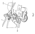
- Figure 2 shows a partial perspective top view of a rotor system with a slider control for a helicopter.
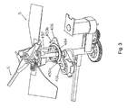
- Figure 3 shows a partial perspective top different view of a rotor system with a slider control for a helicopter.
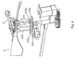
- Figure 4 shows a partial perspective side view of a rotor system with a slider control for a helicopter.
- Figure 5 shows a partial side view of a rotor system with a slider control for a helicopter in a different position of the control and assembly.
- Figure 6 shows a partial perspective side view of a portion of a slider control for a helicopter.
- Figure 7 shows a partial perspective side view of a different portion of a slider control for a helicopter.
- Figure 8 shows a partial perspective side view of a portion of a two slider control for a helicopter.
- Figure 9 shows a partial top view of a portion of a two slider control for a helicopter.
- a helicopter comprises a body, a main rotor with blades which is driven by a rotor shaft the main rotor being hinge mounted on this rotor shaft such that the angle between the plane of rotation of the main rotor and the rotor shaft may vary.
- the control has a control element movable in a first direction such that the control acts to move the angle of incidence in a first direction.
- the control element is movable in a second direction opposite to the first direction such that the control acts to move the angle of incidence in a second direction opposite to the first direction.
- the control element includes an actuator for engaging with a slider element for engagement with an assembly depending from the rotor.
- the inter-engagement of the actuator and slider element in either of the two directions effects a change in the assembly, and the angle of incidence of at least the one blade of the rotor.
- the multiple actuators and multiple sliders are spaced circumferentially around the rotor shaft thereby to interact with the assembly at different circumferential positions relative to the rotor shaft. The interaction occurs when selected actuators are aligned with selected location of the assembly.
- the actuator includes an arm movable between a position of repose and a position of inter-engagement with the slider.
- the degree of movement of and the force exercised by the arm effects the degree of interaction with the slider and in turn the slider with the assembly and the degree of change of angle of inclination of the at least one blade.
- the actuator includes an arm movable between a position of repose and a position of inter-engagement with the slider.
- the length of the arm relative to the length of the assembly from the location of anchoring the rotor to the shaft effects the degree of interaction with the slider and the degree of change of angle of inclination of the at least one blade.
- the actuator includes an arm movable between a position of repose and a position of inter-engagement with the slider.
- the assembly includes a ring transversally located about and movable with the rotor shaft, and the actuator or multiple actuators are located at a fixed location on the body.
- the control system includes a control element that is movable in a first direction such that the control acts to move the angle of incidence in a first direction.
- the control element is also movable in a second direction opposite to the first direction such that the control acts to move the angle of incidence in a second direction opposite to the first direction.
- the control system includes an actuator 416 for engaging with a slider element 406 for engagement with an assembly 452 depending from the rotor 5.
- the inter-engagement of the actuator 416 and slider element 406 in either of the two directions effect a change in the assembly 452, and the angle of incidence of at least the one blade of the rotor 5.
- the actuator can also be non-interfering with slider 406 and, resultantly, the rotor such that the control assembly is in a position of rest relative to the actuator. In such an instance, there would be no command from the actuator 416 to interact with the slider 406, the helicopter retains relative stability.
- actuator pins 450a and 450b Attached at each end of the slider 406 are actuator pins 450a and 450b.
- the actuator pins 450a and 450b push on opposites sides of a ring 404 attached to the assembly 452 allowing the ring to be pushed or pulled by a single actuator 416.
- the pin 450a pushes the ring and makes the rotor tilt along the rotor hinge axis 200.
- the cyclical tilt change cause a different lift force in one blade 12 versus the other and the main rotor 5 moves in the horizontal plane.
- the pin 450b pushes the ring 404 and causes the main rotor 5 to tilt along the rotor hinge axis 200. This cyclical tilt causes a different lift force in one blade versus the other and the rotor moves in the horizontal plane in the opposite direction from previous slide.
- the slider 406 has a slot 408 that allows for the rotor shaft 9 to pass, for guiding the slider while moved by the actuator.
- two controls could be superimposed at a certain rotation to add a second direction of movement. This allows full control in the horizontal plane - up/down and left/right yaw, it adds for/back and side left/side right control.
- the sliders 406 and 506 can be positioned at any angle relative to each other, but are illustrated as positioned at 90 degrees.
- a helicopter can be made in all sorts of shapes and dimensions while still remaining within the scope of the disclosure. In this sense although the helicopter in some senses has been described as toy or model helicopter, the features described and illustrated can have use in part or whole in a full-scale helicopter. In some cases the helicopter may be a structure without a tail rotor. Different helicopter-type systems can use the control of the disclosure. In other cases the rotor control can be used with different flying objects.
- a suitable magnetic or electro magnetic servo can be used for instance with a helicopter using the main rotor and also a stabilizer auxiliary rotor.
- the disclosure has detailed a system for essentially substantial or approximate horizontal movement in one or two directions, the disclosure includes systems for permitting control of the movement in other substantially horizontal directions, without departing from the scope of the appended claims.
- the helicopter control can affect control of horizontal movement forward and/or backwards and/or sideways to the left and/or sideways to the right or different combinations of those movements.
- control system for inter-reacting with the rotor assembly.
- control systems operating on the rotor in parallel and/or series manner to effect the desired horizontal movement.
- the horizontal movements effected by the control systems are in addition to the up and/or down movements which are possible with the helicopter system with the control being non-operation or on-function on the rotor assembly.
Landscapes
- Engineering & Computer Science (AREA)
- Mechanical Engineering (AREA)
- Aviation & Aerospace Engineering (AREA)
- Toys (AREA)
Description
- The present disclosure concerns an improved flying object such as a helicopter.
- The disclosure concerns a helicopter generally. In particular, but not exclusively, it is related to a toy helicopter and in particular to a remote-controlled model helicopter or a toy helicopter.
- Summary
- It is known that a helicopter is a complex machine which is unstable and as a result difficult to control, so that much experience is required to safely operate such helicopters without mishaps.
- Document
US 2007/0164150 A1 discloses a helicopter including a system to effect motion in a horizontal dimension thereby to direct the desired direction. The helicopter comprises a body, a main rotor with which it is driven by a rotor shaft and which is hinge mounted on this rotor shaft, such that the angle between the plane of rotation of the main rotor and the rotor shaft may vary. It further comprises a control for moving the angle of incidence of the blades of the rotor relative to the angle of incidence of other blades of the rotor cyclically at least along part of a 360 degree rotation path around the rotor shaft, causing a variation in lift force of the blade along at least part of the rotation path and thereby causing the body to be urged in a relatively horizontal direction from a relative position of rest. - According to German Utility Model No.
20 2007 000987 , a rotary body arrangement for remote controlled model helicopter has a rotary shaft revolving around a rotary shaft axis at which main rotor blades are engaged around a main rotor blades axis. - Document
EP-A1-1462362 discloses a rotor pitch control mechanism for a model helicopter. The mechanism comprises a seesaw, a stabilizer bar attached to said seesaw, a mixing lever pivotally supported by said stabilizer bar, said mixing lever having a first end and a second end, an upper swash lever to which said first end is connected by way of a rod and a main rotor grip to which said second end is connected by way of said rod. - The present disclosure aims to minimize one or several of the above-mentioned and other disadvantages by providing a simple and cheap solution to auto stabilize the helicopter, such that operating the helicopter becomes simpler and possibly reduces the need for long-standing experience of the pilot.
- This is achieved by a helicopter having the features disclosed in claim 1. The dependent claims outline preferred forms of embodiment of the present invention.
- A helicopter includes a system to effect motion in a horizontal dimension thereby to direct the desired direction, selectively a desired horizontal direction. The rotor blades are driven by and mounted on a rotor shaft, such that the angle between the plane of rotation of the main rotor and the rotor shaft may vary.
- A control moves the angle of incidence of at least one blade of the rotor cyclically along a 360 degree rotation path around the vertical rotor shaft, causing a variation in lift force of the blade along the rotation path thereby cause the body to be urged in a relatively horizontal direction from a relative position of horizontal rest. The relative position of horizontal rest is a relatively hovering position above a ground level. By the term, angle of incidence, there is meant the relative angle of attack of the blade in the plane of rotation.
- The control includes an actuator for engaging with an assembly depending from the rotor the inter-engagement of the actuator and assembly effecting a change in the angle of incidence of at least the one blade of the rotor.
- The control has a control element movable in a first direction such that the control acts to move the angle of incidence in a first direction. The control element is movable in a second direction opposite to the first direction such that the control acts to move the angle of incidence in a second direction opposite to the first direction.
- The control element includes an actuator for engaging with a slider element for engagement with an assembly depending from the rotor. The inter-engagement of the actuator and slider element in either of the two directions effects a change in the assembly, and the angle of incidence of at least the one blade of the rotor. There can be other positions with at least one of the actuator being non-interfering with slider, the rotor, or with the control assembly being in a position of rest relative to the actuator, or there can be no command from the actuator to interact with the slider.
- Illustration of drawings
-
Figure 1 shows a partial side view of a rotor system with a slider control for a helicopter. -
Figure 2 shows a partial perspective top view of a rotor system with a slider control for a helicopter. -
Figure 3 shows a partial perspective top different view of a rotor system with a slider control for a helicopter. -
Figure 4 shows a partial perspective side view of a rotor system with a slider control for a helicopter. -
Figure 5 shows a partial side view of a rotor system with a slider control for a helicopter in a different position of the control and assembly. -
Figure 6 shows a partial perspective side view of a portion of a slider control for a helicopter. -
Figure 7 shows a partial perspective side view of a different portion of a slider control for a helicopter. -
Figure 8 shows a partial perspective side view of a portion of a two slider control for a helicopter. -
Figure 9 shows a partial top view of a portion of a two slider control for a helicopter. - Description of the invention
- A helicopter comprises a body, a main rotor with blades which is driven by a rotor shaft the main rotor being hinge mounted on this rotor shaft such that the angle between the plane of rotation of the main rotor and the rotor shaft may vary.
- There is a control for moving the angle of incidence of at least one blade of the rotor relative to the angle of incidence of another blade of the rotor cyclically along at least part of a 360 degree rotation path around the rotor shaft, causing a variation in lift force of the blade along at least part of the rotation path and thereby cause the body to be urged in a relatively horizontal direction from a relative position of rest.
- The control has a control element movable in a first direction such that the control acts to move the angle of incidence in a first direction. The control element is movable in a second direction opposite to the first direction such that the control acts to move the angle of incidence in a second direction opposite to the first direction.
- The control element includes an actuator for engaging with a slider element for engagement with an assembly depending from the rotor. The inter-engagement of the actuator and slider element in either of the two directions effects a change in the assembly, and the angle of incidence of at least the one blade of the rotor. There can be other positions with at least one of the actuator being non-interfering with slider, the rotor, or with the control assembly being in a position of rest relative to the actuator, or there can be no command from the actuator to interact with the slider.
- There can be multiple actuators and multiple sliders. The multiple actuators and multiple sliders are spaced circumferentially around the rotor shaft thereby to interact with the assembly at different circumferential positions relative to the rotor shaft. The interaction occurs when selected actuators are aligned with selected location of the assembly.
- The actuator includes an arm movable between a position of repose and a position of inter-engagement with the slider. The degree of movement of and the force exercised by the arm effects the degree of interaction with the slider and in turn the slider with the assembly and the degree of change of angle of inclination of the at least one blade.
- The actuator includes an arm movable between a position of repose and a position of inter-engagement with the slider. The length of the arm relative to the length of the assembly from the location of anchoring the rotor to the shaft effects the degree of interaction with the slider and the degree of change of angle of inclination of the at least one blade.
- The actuator includes an arm movable between a position of repose and a position of inter-engagement with the slider. The assembly includes a ring transversally located about and movable with the rotor shaft, and the actuator or multiple actuators are located at a fixed location on the body.
- Description of a preferred form of embodiment
- Referring to
Figures 1 to 9 , a control system for moving a helicopter in a horizontal plane is described. The control system includes a control element that is movable in a first direction such that the control acts to move the angle of incidence in a first direction. The control element is also movable in a second direction opposite to the first direction such that the control acts to move the angle of incidence in a second direction opposite to the first direction. - The control system includes an
actuator 416 for engaging with aslider element 406 for engagement with anassembly 452 depending from therotor 5. The inter-engagement of theactuator 416 andslider element 406 in either of the two directions effect a change in theassembly 452, and the angle of incidence of at least the one blade of therotor 5. The actuator can also be non-interfering withslider 406 and, resultantly, the rotor such that the control assembly is in a position of rest relative to the actuator. In such an instance, there would be no command from theactuator 416 to interact with theslider 406, the helicopter retains relative stability. - Attached at each end of the
slider 406 areactuator pins actuator pins ring 404 attached to theassembly 452 allowing the ring to be pushed or pulled by asingle actuator 416. - When the actuator moves the slider in one direction, the
pin 450a pushes the ring and makes the rotor tilt along therotor hinge axis 200. The cyclical tilt change cause a different lift force in one blade 12 versus the other and themain rotor 5 moves in the horizontal plane. - When the
actuator 416 moves theslider 406 in the opposite direction, thepin 450b pushes thering 404 and causes themain rotor 5 to tilt along therotor hinge axis 200. This cyclical tilt causes a different lift force in one blade versus the other and the rotor moves in the horizontal plane in the opposite direction from previous slide. - The
slider 406 has aslot 408 that allows for therotor shaft 9 to pass, for guiding the slider while moved by the actuator. There is aguide 410 attached along the vertical rotor axis to keep theslider 406 in a fixed vertical position. - Referring to
Figures 8 and9 , two controls could be superimposed at a certain rotation to add a second direction of movement. This allows full control in the horizontal plane - up/down and left/right yaw, it adds for/back and side left/side right control. In this instance, there twoactuators sliders sliders - A helicopter can be made in all sorts of shapes and dimensions while still remaining within the scope of the disclosure. In this sense although the helicopter in some senses has been described as toy or model helicopter, the features described and illustrated can have use in part or whole in a full-scale helicopter. In some cases the helicopter may be a structure without a tail rotor. Different helicopter-type systems can use the control of the disclosure. In other cases the rotor control can be used with different flying objects.
- The present disclosure is not limited to the embodiments described as an example and represented in the accompanying figures. Many different variations in size and scope and features are possible, without departing from the scope of the apended claims.
- The disclosure has been described and illustrated with a self-stabilizing rotor system. Other non-self stabilizing flying devices could also use the control system of the disclosure.
- For instance, instead of electrical motors being provided others forms of motorized power are possible. A different number of blades may be provided to the rotors.
- In other forms instead of the mechanical interaction to effect the control a suitable magnetic or electro magnetic servo can be used for instance with a helicopter using the main rotor and also a stabilizer auxiliary rotor.
- Although the disclosure has detailed a system for essentially substantial or approximate horizontal movement in one or two directions, the disclosure includes systems for permitting control of the movement in other substantially horizontal directions, without departing from the scope of the appended claims. As such, the helicopter control can affect control of horizontal movement forward and/or backwards and/or sideways to the left and/or sideways to the right or different combinations of those movements.
- For this purpose there may be more than the one control system for inter-reacting with the rotor assembly. There could be several control systems operating on the rotor in parallel and/or series manner to effect the desired horizontal movement.
- The horizontal movements effected by the control systems are in addition to the up and/or down movements which are possible with the helicopter system with the control being non-operation or on-function on the rotor assembly.
- In different cases there can be more than two blades for the rotor, and one or two or more of the blades of the rotor can be controlled to different or the same degree.
Claims (5)
- A helicopter comprising a body a main rotor (5) with blades which is driven by a rotor shaft (9), the main rotor being hinge mounted on this rotor shaft (9) by means of a structure (452), such that the angle between the plane of rotation of the main rotor (5) and the rotor shaft (9) may vary; a control for moving the angle of incidence of at least one blade (12) of the rotor (5) relative to the angle of incidence of another blade (12) of the rotor cyclically along at least part of a 360 degree rotation path around the rotor shaft (9), causing a variation in lift force of the blade (12) along at least part of the rotation path and thereby cause the body (2) to be urged in a relatively horizontal direction from a relative position of rest, the control having an actuator (416) movable both in a first direction such that the control acts to move the angle of incidence in a first direction, and in a second direction opposite to the first direction such that the control acts to move the angle of incidence in a second direction opposite to the first direction, characterized in that the control includes a slider element (406) for sliding movement transverse to the rotor shaft (9), the slider element being located between an actuator (416) and a structure (452), and wherein said slider element (406) includes a pin (450a, 450b) fixedly mounted on the slider element and extending in a direction transverse to the direction of the sliding action, the pin being for engaging a ring (404) associated with the structure (452), whereby the movement generated in either one of two directions by said slider element (406) through said actuator (416) results in a position change of said structure (452), as well as in a change of the angle of incidence of the blades of the rotor (5).
- A helicopter according to claim 1 characterized in that said actuator (416) of said control has a position in which it does not interfere with said slider element (406), whereby said rotor (5) or said structure (452) are in a position of rest relative to said actuator (416), or there being no command from the actuator (416) to interact with the slider element (406).
- A helicopter according to claim 1 characterized in that it includes multiple actuators (416 and 516) and multiple sliders (406 and 506), the multiple actuators and multiple sliders being spaced circumferentially around the rotor shaft (9) thereby to interact with the structure (452) at different circumferential positions relative to the rotor shaft (9), the interaction occurring when selected actuators are aligned with selected location of the structure (452).
- A helicopter as claimed in anyone of Claims 1 to 3 characterized in that the actuator (416) includes an arm movable between a position of repose and a position of inter-engagement with the slider (406) and in that the degree of movement of and the force exercised by the arm effects the degree of interaction with the slider element (406) and in turn the slider element (406) with the structure (452) and the degree of change of angle of inclination of the at least one blade (12).
- A helicopter as claimed in anyone of Claims 1 to 4 characterized in that the actuator (416) includes an arm movable between a position of repose and a position of inter-engagement with the slider (406) and in that the length of the arm relative to the length of the assembly structure (452) from the location of anchoring the rotor (5) to the shaft (9) effects the degree of interaction with the slider (406) and the degree of change of angle of inclination of the at least one blade (12).
Priority Applications (1)
| Application Number | Priority Date | Filing Date | Title |
|---|---|---|---|
| EP09170725.7A EP2298644B1 (en) | 2009-09-18 | 2009-09-18 | Helicopter |
Applications Claiming Priority (1)
| Application Number | Priority Date | Filing Date | Title |
|---|---|---|---|
| EP09170725.7A EP2298644B1 (en) | 2009-09-18 | 2009-09-18 | Helicopter |
Publications (2)
| Publication Number | Publication Date |
|---|---|
| EP2298644A1 EP2298644A1 (en) | 2011-03-23 |
| EP2298644B1 true EP2298644B1 (en) | 2013-05-29 |
Family
ID=41650499
Family Applications (1)
| Application Number | Title | Priority Date | Filing Date |
|---|---|---|---|
| EP09170725.7A Not-in-force EP2298644B1 (en) | 2009-09-18 | 2009-09-18 | Helicopter |
Country Status (1)
| Country | Link |
|---|---|
| EP (1) | EP2298644B1 (en) |
Families Citing this family (1)
| Publication number | Priority date | Publication date | Assignee | Title |
|---|---|---|---|---|
| FR3123048B1 (en) * | 2021-05-21 | 2023-04-14 | Airbus Helicopters | Electromechanical servo, swashplate system having at least four electromechanical servos and rotorcraft |
Citations (1)
| Publication number | Priority date | Publication date | Assignee | Title |
|---|---|---|---|---|
| US3228478A (en) * | 1964-04-29 | 1966-01-11 | Bell Aerospace Corp | Control lag compensator for rotary wing aircraft |
Family Cites Families (3)
| Publication number | Priority date | Publication date | Assignee | Title |
|---|---|---|---|---|
| US20040184915A1 (en) | 2003-03-21 | 2004-09-23 | Makoto Kunii | Model helicopter rotor pitch control mechanism |
| US7662013B2 (en) | 2006-01-19 | 2010-02-16 | Silverlit Toys Manufactory Ltd. | Helicopter with horizontal control |
| DE202007000987U1 (en) | 2007-01-23 | 2007-04-12 | Dauschek Klaus | Rotary body arrangement for remote controlled model helicopter, has rotary shaft revolving around rotary shaft axis at which main rotor blades are engaged around main rotor blades axis |
-
2009
- 2009-09-18 EP EP09170725.7A patent/EP2298644B1/en not_active Not-in-force
Patent Citations (1)
| Publication number | Priority date | Publication date | Assignee | Title |
|---|---|---|---|---|
| US3228478A (en) * | 1964-04-29 | 1966-01-11 | Bell Aerospace Corp | Control lag compensator for rotary wing aircraft |
Also Published As
| Publication number | Publication date |
|---|---|
| EP2298644A1 (en) | 2011-03-23 |
Similar Documents
| Publication | Publication Date | Title |
|---|---|---|
| EP2516268B1 (en) | Rotor assembly | |
| EP2119626B1 (en) | Control lever assembly for a tilt-rotor aircraft | |
| KR101849246B1 (en) | Tilt-prop aircraft | |
| US8052500B2 (en) | Helicopter with main and auxiliary rotors | |
| EP1533012A1 (en) | Toy radio-controlled helicopter | |
| US11053000B2 (en) | Aerodyne with vertical-takeoff-and-landing ability | |
| US9561850B2 (en) | Vertical take-off and landing aircraft | |
| EP2669188B1 (en) | A hinge assembly for rotatably mounting a control surface on an aircraft | |
| KR20150038447A (en) | Vertical-takeoff aircraft | |
| EP3121117A1 (en) | Control system and strategy for tail sitter | |
| EP3186146B1 (en) | Pitch control system | |
| KR20150070951A (en) | A rotorcraft fitted with an anti-torque tail rotor that contributes selectively to providing the rotorcraft with lift and with propulsion in translation | |
| EP1977970A2 (en) | User interface passive haptic feedback system | |
| US20230294818A1 (en) | Electromechanical Blade Pitch Control | |
| JP2009051381A (en) | Cycloidal blade | |
| KR20180062430A (en) | A control member, a rotary wing aircraft, and a method | |
| KR101664899B1 (en) | multicopter | |
| KR102674232B1 (en) | Convertible aircraft and its control method | |
| US3765622A (en) | Aircraft control means | |
| KR101109619B1 (en) | Wing Rotation Structure | |
| EP3293113B1 (en) | Rotor for a hover-capable aircraft and related method of control | |
| JP5014301B2 (en) | Center of gravity adjustment device | |
| KR101625148B1 (en) | A dual type flight control system | |
| JPS6327758Y2 (en) | ||
| WO1997044240A1 (en) | Vertical take-off aircraft |
Legal Events
| Date | Code | Title | Description |
|---|---|---|---|
| PUAI | Public reference made under article 153(3) epc to a published international application that has entered the european phase |
Free format text: ORIGINAL CODE: 0009012 |
|
| AK | Designated contracting states |
Kind code of ref document: A1 Designated state(s): AT BE BG CH CY CZ DE DK EE ES FI FR GB GR HR HU IE IS IT LI LT LU LV MC MK MT NL NO PL PT RO SE SI SK SM TR |
|
| AX | Request for extension of the european patent |
Extension state: AL BA RS |
|
| 17P | Request for examination filed |
Effective date: 20110713 |
|
| 17Q | First examination report despatched |
Effective date: 20110812 |
|
| REG | Reference to a national code |
Ref country code: HK Ref legal event code: DE Ref document number: 1150817 Country of ref document: HK |
|
| GRAP | Despatch of communication of intention to grant a patent |
Free format text: ORIGINAL CODE: EPIDOSNIGR1 |
|
| RIN1 | Information on inventor provided before grant (corrected) |
Inventor name: VAN DE ROSTYNE, ALEXANDER JOZEF MAGDALENA Inventor name: WAI, CHI POK BILLY |
|
| GRAS | Grant fee paid |
Free format text: ORIGINAL CODE: EPIDOSNIGR3 |
|
| GRAA | (expected) grant |
Free format text: ORIGINAL CODE: 0009210 |
|
| AK | Designated contracting states |
Kind code of ref document: B1 Designated state(s): AT BE BG CH CY CZ DE DK EE ES FI FR GB GR HR HU IE IS IT LI LT LU LV MC MK MT NL NO PL PT RO SE SI SK SM TR |
|
| REG | Reference to a national code |
Ref country code: GB Ref legal event code: FG4D |
|
| REG | Reference to a national code |
Ref country code: CH Ref legal event code: EP |
|
| REG | Reference to a national code |
Ref country code: AT Ref legal event code: REF Ref document number: 614214 Country of ref document: AT Kind code of ref document: T Effective date: 20130615 |
|
| REG | Reference to a national code |
Ref country code: IE Ref legal event code: FG4D |
|
| REG | Reference to a national code |
Ref country code: DE Ref legal event code: R096 Ref document number: 602009015966 Country of ref document: DE Effective date: 20130725 |
|
| REG | Reference to a national code |
Ref country code: AT Ref legal event code: MK05 Ref document number: 614214 Country of ref document: AT Kind code of ref document: T Effective date: 20130529 |
|
| REG | Reference to a national code |
Ref country code: LT Ref legal event code: MG4D |
|
| PG25 | Lapsed in a contracting state [announced via postgrant information from national office to epo] |
Ref country code: ES Free format text: LAPSE BECAUSE OF FAILURE TO SUBMIT A TRANSLATION OF THE DESCRIPTION OR TO PAY THE FEE WITHIN THE PRESCRIBED TIME-LIMIT Effective date: 20130909 Ref country code: PT Free format text: LAPSE BECAUSE OF FAILURE TO SUBMIT A TRANSLATION OF THE DESCRIPTION OR TO PAY THE FEE WITHIN THE PRESCRIBED TIME-LIMIT Effective date: 20130930 Ref country code: LT Free format text: LAPSE BECAUSE OF FAILURE TO SUBMIT A TRANSLATION OF THE DESCRIPTION OR TO PAY THE FEE WITHIN THE PRESCRIBED TIME-LIMIT Effective date: 20130529 Ref country code: GR Free format text: LAPSE BECAUSE OF FAILURE TO SUBMIT A TRANSLATION OF THE DESCRIPTION OR TO PAY THE FEE WITHIN THE PRESCRIBED TIME-LIMIT Effective date: 20130830 Ref country code: FI Free format text: LAPSE BECAUSE OF FAILURE TO SUBMIT A TRANSLATION OF THE DESCRIPTION OR TO PAY THE FEE WITHIN THE PRESCRIBED TIME-LIMIT Effective date: 20130529 Ref country code: NO Free format text: LAPSE BECAUSE OF FAILURE TO SUBMIT A TRANSLATION OF THE DESCRIPTION OR TO PAY THE FEE WITHIN THE PRESCRIBED TIME-LIMIT Effective date: 20130829 Ref country code: SI Free format text: LAPSE BECAUSE OF FAILURE TO SUBMIT A TRANSLATION OF THE DESCRIPTION OR TO PAY THE FEE WITHIN THE PRESCRIBED TIME-LIMIT Effective date: 20130529 Ref country code: IS Free format text: LAPSE BECAUSE OF FAILURE TO SUBMIT A TRANSLATION OF THE DESCRIPTION OR TO PAY THE FEE WITHIN THE PRESCRIBED TIME-LIMIT Effective date: 20130929 Ref country code: SE Free format text: LAPSE BECAUSE OF FAILURE TO SUBMIT A TRANSLATION OF THE DESCRIPTION OR TO PAY THE FEE WITHIN THE PRESCRIBED TIME-LIMIT Effective date: 20130529 Ref country code: AT Free format text: LAPSE BECAUSE OF FAILURE TO SUBMIT A TRANSLATION OF THE DESCRIPTION OR TO PAY THE FEE WITHIN THE PRESCRIBED TIME-LIMIT Effective date: 20130529 |
|
| REG | Reference to a national code |
Ref country code: NL Ref legal event code: VDEP Effective date: 20130529 |
|
| REG | Reference to a national code |
Ref country code: GB Ref legal event code: 732E Free format text: REGISTERED BETWEEN 20131031 AND 20131106 |
|
| PG25 | Lapsed in a contracting state [announced via postgrant information from national office to epo] |
Ref country code: HR Free format text: LAPSE BECAUSE OF FAILURE TO SUBMIT A TRANSLATION OF THE DESCRIPTION OR TO PAY THE FEE WITHIN THE PRESCRIBED TIME-LIMIT Effective date: 20130529 Ref country code: BG Free format text: LAPSE BECAUSE OF FAILURE TO SUBMIT A TRANSLATION OF THE DESCRIPTION OR TO PAY THE FEE WITHIN THE PRESCRIBED TIME-LIMIT Effective date: 20130829 Ref country code: PL Free format text: LAPSE BECAUSE OF FAILURE TO SUBMIT A TRANSLATION OF THE DESCRIPTION OR TO PAY THE FEE WITHIN THE PRESCRIBED TIME-LIMIT Effective date: 20130529 |
|
| PG25 | Lapsed in a contracting state [announced via postgrant information from national office to epo] |
Ref country code: LV Free format text: LAPSE BECAUSE OF FAILURE TO SUBMIT A TRANSLATION OF THE DESCRIPTION OR TO PAY THE FEE WITHIN THE PRESCRIBED TIME-LIMIT Effective date: 20130529 |
|
| PG25 | Lapsed in a contracting state [announced via postgrant information from national office to epo] |
Ref country code: BE Free format text: LAPSE BECAUSE OF FAILURE TO SUBMIT A TRANSLATION OF THE DESCRIPTION OR TO PAY THE FEE WITHIN THE PRESCRIBED TIME-LIMIT Effective date: 20130529 Ref country code: DK Free format text: LAPSE BECAUSE OF FAILURE TO SUBMIT A TRANSLATION OF THE DESCRIPTION OR TO PAY THE FEE WITHIN THE PRESCRIBED TIME-LIMIT Effective date: 20130529 Ref country code: CZ Free format text: LAPSE BECAUSE OF FAILURE TO SUBMIT A TRANSLATION OF THE DESCRIPTION OR TO PAY THE FEE WITHIN THE PRESCRIBED TIME-LIMIT Effective date: 20130529 Ref country code: EE Free format text: LAPSE BECAUSE OF FAILURE TO SUBMIT A TRANSLATION OF THE DESCRIPTION OR TO PAY THE FEE WITHIN THE PRESCRIBED TIME-LIMIT Effective date: 20130529 Ref country code: SK Free format text: LAPSE BECAUSE OF FAILURE TO SUBMIT A TRANSLATION OF THE DESCRIPTION OR TO PAY THE FEE WITHIN THE PRESCRIBED TIME-LIMIT Effective date: 20130529 |
|
| PG25 | Lapsed in a contracting state [announced via postgrant information from national office to epo] |
Ref country code: IT Free format text: LAPSE BECAUSE OF FAILURE TO SUBMIT A TRANSLATION OF THE DESCRIPTION OR TO PAY THE FEE WITHIN THE PRESCRIBED TIME-LIMIT Effective date: 20130529 Ref country code: NL Free format text: LAPSE BECAUSE OF FAILURE TO SUBMIT A TRANSLATION OF THE DESCRIPTION OR TO PAY THE FEE WITHIN THE PRESCRIBED TIME-LIMIT Effective date: 20130529 Ref country code: RO Free format text: LAPSE BECAUSE OF FAILURE TO SUBMIT A TRANSLATION OF THE DESCRIPTION OR TO PAY THE FEE WITHIN THE PRESCRIBED TIME-LIMIT Effective date: 20130529 |
|
| PLBE | No opposition filed within time limit |
Free format text: ORIGINAL CODE: 0009261 |
|
| STAA | Information on the status of an ep patent application or granted ep patent |
Free format text: STATUS: NO OPPOSITION FILED WITHIN TIME LIMIT |
|
| PG25 | Lapsed in a contracting state [announced via postgrant information from national office to epo] |
Ref country code: MC Free format text: LAPSE BECAUSE OF FAILURE TO SUBMIT A TRANSLATION OF THE DESCRIPTION OR TO PAY THE FEE WITHIN THE PRESCRIBED TIME-LIMIT Effective date: 20130529 |
|
| REG | Reference to a national code |
Ref country code: CH Ref legal event code: PL |
|
| 26N | No opposition filed |
Effective date: 20140303 |
|
| REG | Reference to a national code |
Ref country code: DE Ref legal event code: R097 Ref document number: 602009015966 Country of ref document: DE Effective date: 20140303 |
|
| REG | Reference to a national code |
Ref country code: IE Ref legal event code: MM4A |
|
| PG25 | Lapsed in a contracting state [announced via postgrant information from national office to epo] |
Ref country code: IE Free format text: LAPSE BECAUSE OF NON-PAYMENT OF DUE FEES Effective date: 20130918 Ref country code: CH Free format text: LAPSE BECAUSE OF NON-PAYMENT OF DUE FEES Effective date: 20130930 Ref country code: LI Free format text: LAPSE BECAUSE OF NON-PAYMENT OF DUE FEES Effective date: 20130930 |
|
| PG25 | Lapsed in a contracting state [announced via postgrant information from national office to epo] |
Ref country code: SM Free format text: LAPSE BECAUSE OF FAILURE TO SUBMIT A TRANSLATION OF THE DESCRIPTION OR TO PAY THE FEE WITHIN THE PRESCRIBED TIME-LIMIT Effective date: 20130529 |
|
| PG25 | Lapsed in a contracting state [announced via postgrant information from national office to epo] |
Ref country code: MT Free format text: LAPSE BECAUSE OF FAILURE TO SUBMIT A TRANSLATION OF THE DESCRIPTION OR TO PAY THE FEE WITHIN THE PRESCRIBED TIME-LIMIT Effective date: 20130529 Ref country code: TR Free format text: LAPSE BECAUSE OF FAILURE TO SUBMIT A TRANSLATION OF THE DESCRIPTION OR TO PAY THE FEE WITHIN THE PRESCRIBED TIME-LIMIT Effective date: 20130529 Ref country code: CY Free format text: LAPSE BECAUSE OF FAILURE TO SUBMIT A TRANSLATION OF THE DESCRIPTION OR TO PAY THE FEE WITHIN THE PRESCRIBED TIME-LIMIT Effective date: 20130529 |
|
| PG25 | Lapsed in a contracting state [announced via postgrant information from national office to epo] |
Ref country code: HU Free format text: LAPSE BECAUSE OF FAILURE TO SUBMIT A TRANSLATION OF THE DESCRIPTION OR TO PAY THE FEE WITHIN THE PRESCRIBED TIME-LIMIT; INVALID AB INITIO Effective date: 20090918 Ref country code: MK Free format text: LAPSE BECAUSE OF FAILURE TO SUBMIT A TRANSLATION OF THE DESCRIPTION OR TO PAY THE FEE WITHIN THE PRESCRIBED TIME-LIMIT Effective date: 20130529 Ref country code: LU Free format text: LAPSE BECAUSE OF NON-PAYMENT OF DUE FEES Effective date: 20130918 |
|
| REG | Reference to a national code |
Ref country code: FR Ref legal event code: PLFP Year of fee payment: 7 |
|
| PGFP | Annual fee paid to national office [announced via postgrant information from national office to epo] |
Ref country code: GB Payment date: 20150907 Year of fee payment: 7 Ref country code: DE Payment date: 20150916 Year of fee payment: 7 |
|
| PGFP | Annual fee paid to national office [announced via postgrant information from national office to epo] |
Ref country code: FR Payment date: 20150923 Year of fee payment: 7 |
|
| REG | Reference to a national code |
Ref country code: DE Ref legal event code: R119 Ref document number: 602009015966 Country of ref document: DE |
|
| GBPC | Gb: european patent ceased through non-payment of renewal fee |
Effective date: 20160918 |
|
| REG | Reference to a national code |
Ref country code: FR Ref legal event code: ST Effective date: 20170531 |
|
| PG25 | Lapsed in a contracting state [announced via postgrant information from national office to epo] |
Ref country code: DE Free format text: LAPSE BECAUSE OF NON-PAYMENT OF DUE FEES Effective date: 20170401 Ref country code: FR Free format text: LAPSE BECAUSE OF NON-PAYMENT OF DUE FEES Effective date: 20160930 Ref country code: GB Free format text: LAPSE BECAUSE OF NON-PAYMENT OF DUE FEES Effective date: 20160918 |
|
| REG | Reference to a national code |
Ref country code: HK Ref legal event code: WD Ref document number: 1150817 Country of ref document: HK |