EP2298611A2 - Slide switch for buckle apparatus - Google Patents
Slide switch for buckle apparatus Download PDFInfo
- Publication number
- EP2298611A2 EP2298611A2 EP10176049A EP10176049A EP2298611A2 EP 2298611 A2 EP2298611 A2 EP 2298611A2 EP 10176049 A EP10176049 A EP 10176049A EP 10176049 A EP10176049 A EP 10176049A EP 2298611 A2 EP2298611 A2 EP 2298611A2
- Authority
- EP
- European Patent Office
- Prior art keywords
- slider
- fixed contact
- slide switch
- buckle apparatus
- fixed
- Prior art date
- Legal status (The legal status is an assumption and is not a legal conclusion. Google has not performed a legal analysis and makes no representation as to the accuracy of the status listed.)
- Granted
Links
Images


Classifications
-
- B—PERFORMING OPERATIONS; TRANSPORTING
- B60—VEHICLES IN GENERAL
- B60R—VEHICLES, VEHICLE FITTINGS, OR VEHICLE PARTS, NOT OTHERWISE PROVIDED FOR
- B60R22/00—Safety belts or body harnesses in vehicles
- B60R22/48—Control systems, alarms, or interlock systems, for the correct application of the belt or harness
-
- A—HUMAN NECESSITIES
- A44—HABERDASHERY; JEWELLERY
- A44B—BUTTONS, PINS, BUCKLES, SLIDE FASTENERS, OR THE LIKE
- A44B11/00—Buckles; Similar fasteners for interconnecting straps or the like, e.g. for safety belts
- A44B11/25—Buckles; Similar fasteners for interconnecting straps or the like, e.g. for safety belts with two or more separable parts
-
- H—ELECTRICITY
- H01—ELECTRIC ELEMENTS
- H01H—ELECTRIC SWITCHES; RELAYS; SELECTORS; EMERGENCY PROTECTIVE DEVICES
- H01H13/00—Switches having rectilinearly-movable operating part or parts adapted for pushing or pulling in one direction only, e.g. push-button switch
- H01H13/02—Details
- H01H13/12—Movable parts; Contacts mounted thereon
- H01H13/14—Operating parts, e.g. push-button
- H01H13/18—Operating parts, e.g. push-button adapted for actuation at a limit or other predetermined position in the path of a body, the relative movement of switch and body being primarily for a purpose other than the actuation of the switch, e.g. door switch, limit switch, floor-levelling switch of a lift
-
- H—ELECTRICITY
- H01—ELECTRIC ELEMENTS
- H01H—ELECTRIC SWITCHES; RELAYS; SELECTORS; EMERGENCY PROTECTIVE DEVICES
- H01H15/00—Switches having rectilinearly-movable operating part or parts adapted for actuation in opposite directions, e.g. slide switch
- H01H15/02—Details
- H01H15/06—Movable parts; Contacts mounted thereon
-
- B—PERFORMING OPERATIONS; TRANSPORTING
- B60—VEHICLES IN GENERAL
- B60R—VEHICLES, VEHICLE FITTINGS, OR VEHICLE PARTS, NOT OTHERWISE PROVIDED FOR
- B60R22/00—Safety belts or body harnesses in vehicles
- B60R22/48—Control systems, alarms, or interlock systems, for the correct application of the belt or harness
- B60R2022/4808—Sensing means arrangements therefor
- B60R2022/4816—Sensing means arrangements therefor for sensing locking of buckle
-
- Y—GENERAL TAGGING OF NEW TECHNOLOGICAL DEVELOPMENTS; GENERAL TAGGING OF CROSS-SECTIONAL TECHNOLOGIES SPANNING OVER SEVERAL SECTIONS OF THE IPC; TECHNICAL SUBJECTS COVERED BY FORMER USPC CROSS-REFERENCE ART COLLECTIONS [XRACs] AND DIGESTS
- Y10—TECHNICAL SUBJECTS COVERED BY FORMER USPC
- Y10T—TECHNICAL SUBJECTS COVERED BY FORMER US CLASSIFICATION
- Y10T24/00—Buckles, buttons, clasps, etc.
- Y10T24/45—Separable-fastener or required component thereof [e.g., projection and cavity to complete interlock]
- Y10T24/45225—Separable-fastener or required component thereof [e.g., projection and cavity to complete interlock] including member having distinct formations and mating member selectively interlocking therewith
- Y10T24/45471—Projection having movable connection between components thereof or variable configuration
- Y10T24/45482—Projection having movable connection between components thereof or variable configuration and operator therefor
-
- Y—GENERAL TAGGING OF NEW TECHNOLOGICAL DEVELOPMENTS; GENERAL TAGGING OF CROSS-SECTIONAL TECHNOLOGIES SPANNING OVER SEVERAL SECTIONS OF THE IPC; TECHNICAL SUBJECTS COVERED BY FORMER USPC CROSS-REFERENCE ART COLLECTIONS [XRACs] AND DIGESTS
- Y10—TECHNICAL SUBJECTS COVERED BY FORMER USPC
- Y10T—TECHNICAL SUBJECTS COVERED BY FORMER US CLASSIFICATION
- Y10T24/00—Buckles, buttons, clasps, etc.
- Y10T24/45—Separable-fastener or required component thereof [e.g., projection and cavity to complete interlock]
- Y10T24/45225—Separable-fastener or required component thereof [e.g., projection and cavity to complete interlock] including member having distinct formations and mating member selectively interlocking therewith
- Y10T24/45602—Receiving member includes either movable connection between interlocking components or variable configuration cavity
- Y10T24/45623—Receiving member includes either movable connection between interlocking components or variable configuration cavity and operator therefor
Definitions
- the present invention relates to a slide switch installed in a buckle apparatus into which a tongue (tongue plate) attached to a seatbelt is inserted and mated so as to determine whether a passenger fastens the seatbelt.
- Fig. 1 shows the structure of a slide switch of this type disclosed in Japanese Utility Model Application Publication No. H4-101611 .
- the slide switch includes a fixed plate 11 placed in a buckle apparatus and a movable contact 12 attached to the fixed plate 11.
- Three fixed contacts 13 to 15 are formed on the fixed plate 11; the fixed contact 13 positions on one side in the width direction of the fixed plate 11 and extends across both ends of the fixed plate 11.
- the fixed contact 14 positions on the other side in the width direction of the fixed plate 11 and extends from one end to a midpoint in the fixed plate 11.
- the fixed contact 15 positions on the other side in the width direction of the fixed plate 11 and extends from the midpoint to the other end of the fixed plate 11.
- the movable contact 12 which includes blade springs, has a pair of feet 12a on both ends in the width direction and the feet 12a have L-shaped holding parts 12b, which bends so as to get close to each other.
- An opening 12c is formed at the center of the movable contact 12 and a pair of arms 12d and 12e extend in the longitudinal direction of the foot 12a from one side of the opening 12c.
- reference numeral 16 indicates an ejector of the buckle apparatus that slides when the tongue is inserted and reference numeral 17 indicates a compressed coil spring that urges the ejector 16 in a direction in which the tongue is removed.
- a projection 16a of the ejector 16 positions in the opening 12c of the movable contact 12 and the ejector 16 is mated into the movable contact 12, and the movable contact 12 slides when pressed by the ejector 16.
- the arm 12d of the movable contact 12 is constantly in contact with the fixed contact 13 regardless of the slide position of the movable contact 12.
- the arm 12e makes contact with the fixed contact 14 or the fixed contact 15 depending on the attachment state of the tongue. This can be used to determine whether the tongue is removed from or inserted and mated into the buckle apparatus.
- the problem with the slide switch of the above structure is that the fixed contact is like to be fouled or affected by foreign matter during or before installation in the buckle apparatus because the fixed contacts are much exposed.
- the present invention addresses the above problems with the object of providing a reliable and easy-to-use slide switch installed in a buckle apparatus for which the fixed contacts are unlikely to be affected by foreign matter and grease applied to the fixed contact is unlikely to be transferred or adhere to other portions.
- the fixed contact is constantly obscured by the slider, so the fixed contacts are unlikely to be affected by foreign matter and adherence of dust etc. can be prevented.
- the present invention achieves the reliable and easy-to-use slide switch installed in a buckle apparatus without degrading performance due to adherence of foreign matter etc.
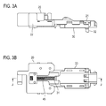
- Figs. 2A and 2B and Figs. 3A and 3B show the appearance of an embodiment of the slide switch installed in a buckle apparatus according to the present invention
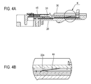
- Figs. 4A and 4B show the cross-sectional structure of the embodiment.
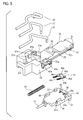
- Figs. 5 and 6 are exploded perspective views. Figs. 5 and 6 also show harnesses together.
- the slide switch in this example includes a body 20, a slider 30, first to third fixed contacts 41 to 43, a movable piece 44, and a spring 45.
- Slightly concave portions 22a are formed on an under surface of the extending part 22 and the first to third fixed contacts 41 to 43 are placed in these concave portions and are exposed externally.
- the first fixed contact 41 positions on a first half side in the width direction of the extending part 22 and extends in the longitudinal direction of the extending part 22.
- the second fixed contact 42 and the third fixed contact 43 position on a second half side in the width direction of the extending part 22 and extend in the longitudinal direction of the extending part 22 in sequence.
- One end of the first fixed contact 41 is aligned with one end of the third fixed contact 43 in the longitudinal direction of the extending part 22.
- grooves 22b are formed on both ends in the width direction excluding the tips of the extending part 22. That is, the grooves 22b extend from the base end to the position before the tip of the extending part 22.
- Three concave portions 21a are formed on the upper surface of the base unit 21; terminals 41a to 43a, which extend from the fixed contacts 41 to 43, position in the concave portions 21a.
- a hole 21b is disposed, in the longitudinal direction of the extending part 22, on an under surface of the base unit 21, and a groove 21c is formed from the extending part 22 to the hole 21b.
- a groove 21d and a projection 21e which are used to route and position harnesses, are formed on the upper surface of the base unit 21 and a hook 21f extending backward is formed.
- a stopper 23 projecting downward is formed at the tip of the extending part 22.
- Projections 24, which extend from the top of the extending part 22 and project in the width direction (horizontal direction) of the extending part 22, a convex portion 25, which is disposed in the middle of the extending part 22, projections 26, which are disposed on the convex portion 25, projections 27, which are disposed on the under surface of the base unit 21, etc. are used to perform positioning or prevent looseness when the body 20 is installed in a buckle apparatus.
- the main body of the slider 30 is a substantially rectangular plate and a shaft 31 projects from one side in parallel with the surface of the plate.
- a pair of projections 32 which project downward, are placed at both ends in the width direction.
- a pair of engaging pieces 33 and a pair of engaging pieces 34 project from the upper surface of the slider 30 in the width direction orthogonal to the movement direction of the slider 30.
- a pair of engaging hooks 33a which face each other, project from the pair of engaging pieces 33 and a pair of engaging hooks 34a, which face each other, project from the pair of engaging pieces 34.
- the slider 30 is made of resin.
- the movable piece 44 includes blade springs, which have a fixed part 44a and a pair of feet 44b supported by the fixed part 44a. Arc-shaped contact parts 44c are formed at the tips (free end) of the feet 44b, which are bent relative to the fixed part 44a.
- the movable piece 44 is attached to the upper surface of the slider 30.
- dowels 35 formed on the upper surface of the slider 30 are inserted into a pair of holes 44d formed on the fixed part 44a of the movable piece 44 and then the tips are heat-swaged.
- a pair of extending pieces 44e project from the fixed part 44a of the movable piece 44 in the direction opposite to the direction of the feet 44b and the extending pieces 44e are inserted into a pair of holes 36a formed in a side of a convex portion 36 projecting from the upper surface of the slider 30. This prevents the fixed part 44a from being floated and the movable piece 44 is well secured to the slider 30.
- the slider 30 holding movable piece 44 is held in the body 20 with the engaging hooks 33a and 34a of the engaging pieces 33 and 34 engaged with the grooves 22b of the extending part 22 of the body 20 so that the slider 30 can slide in the extending direction of the extending unit 22.
- the spring 45 is attached with the shaft 31 of the slider 30 inserted into one end of the spring 45 and the other end inserted into the hole 21b of the body 20. That is, the spring 45 is placed between the body 20 and the slider 30.
- the slider 30 is urged by the spring 45 including a compressed coil spring and the end surface is pressed against the stopper 23 projecting from the under surface of the extending unit 22 of the body 20 in the initial position.
- Fig. 7 shows the state where, for example, two harnesses 46 and 48 of three harnesses 46 to 48 shown in Figs. 5 and 6 are attached to the slide switch.
- a hole 28 is formed so as to pass through the terminals 41a to 43a and the body 20, and the tips of the harness 46 and 48 are inserted into the hole 28 and soldered.
- Figs. 8A and 8B show the relationship between a movable part 51 disposed in the buckle apparatus to which this slide switch is installed and the slide switch.
- the movable part 51 is simplified.
- the movable part 51 slides when the tongue of the sheet belt is inserted into the buckle apparatus, makes contact with the projection 32 on the end surface of the slider 30 as shown in Fig. 8B , and presses the slider 30 to let it slide.
- Figs. 9A and 9B show the initial position of the slider 30 when the tongue is unlatched and the movement position of the slider 30 when the tongue is latched.
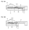
- Figs. 10A and 10B are enlarge views of the section M-M in Fig. 9A and the section N-N in Fig. 9B , respectively.
- the fixed contacts 41 to 43 are placed in the movement direction of the slider 30 on a surface of the extending part 22 of the body 20, the surface closely facing the slider 30.
- the movable piece 44 slides on the surface of the body 20 on which the fixed contacts are placed as the slider 30 slides.
- the first fixed contact 41 extends across the entire sliding path of one of the pair of feet 44b of the movable piece 44 and the second fixed contact 42 and the third fixed contacts 43 extend in sequence in the sliding path of the other of the pair of feet 44b.
- the contact parts 44c at the tip of the feet 44b of the movable piece 44 make contact with the first fixed contact 41 and the third fixed contact 43 and the first fixed contact 41 and the third fixed contact 43 are electrically connected (closed).
- the feet 44b of the movable piece 44 make contact with the first fixed contact 41 and the second fixed contact 42 and the first fixed contact 41 and the third fixed contact 43 are electrically disconnected (opened) and the first fixed contact 41 and the second fixed contact 42 are electrically connected (closed).
- the contact state of the movable piece 44 changes as the slider 30 moves as described above, so it is possible to determine whether the tongue is latched into (insertion and mating state) or unlatched from (removal state) the buckle apparatus according to this state.
- the ON signal in the initial position and the ON signal in the movement position can be obtained. If the two harnesses 46 and 48 are soldered as shown in Fig. 7 , a detection method in which the ON signal in the movement position (tongue latch state) can be obtained. This detection method may be used.
- the slider 30 has a size that obscures the fixed contacts 41 to 43 across the entire length of sliding motion as shown in Figs. 9A and 9B . That is, the slider 30 covers the fixed contacts 41 to 43 to prevent them from being exposed externally. Accordingly, the fixed contacts 41 to 43 are unlikely to be affected by foreign matter, preventing foreign matter such as dust from being attached and performance from being degraded by attachment of foreign matter. Therefore, the slide switch with high dust resistance and high reliability can be obtained.
Landscapes
- Engineering & Computer Science (AREA)
- Automation & Control Theory (AREA)
- Mechanical Engineering (AREA)
- Slide Switches (AREA)
- Buckles (AREA)
Abstract
Description
- The present invention relates to a slide switch installed in a buckle apparatus into which a tongue (tongue plate) attached to a seatbelt is inserted and mated so as to determine whether a passenger fastens the seatbelt.
-
Fig. 1 shows the structure of a slide switch of this type disclosed in Japanese Utility Model Application Publication No.H4-101611 fixed plate 11 placed in a buckle apparatus and amovable contact 12 attached to thefixed plate 11. - Three
fixed contacts 13 to 15 are formed on thefixed plate 11; thefixed contact 13 positions on one side in the width direction of thefixed plate 11 and extends across both ends of thefixed plate 11. The fixedcontact 14 positions on the other side in the width direction of thefixed plate 11 and extends from one end to a midpoint in thefixed plate 11. The fixedcontact 15 positions on the other side in the width direction of thefixed plate 11 and extends from the midpoint to the other end of thefixed plate 11. - The
movable contact 12, which includes blade springs, has a pair offeet 12a on both ends in the width direction and thefeet 12a have L-shaped holding parts 12b, which bends so as to get close to each other. An opening 12c is formed at the center of themovable contact 12 and a pair ofarms foot 12a from one side of the opening 12c. - The
movable contact 12 is slidably attached to thefixed plate 11 with theholding parts 12b in contact with the undersurface of thefixed plate 11 at both ends in the width direction of thefixed plate 11 and the pair of thearms fixed contacts 13 to 15. InFig. 1 ,reference numeral 16 indicates an ejector of the buckle apparatus that slides when the tongue is inserted andreference numeral 17 indicates a compressed coil spring that urges theejector 16 in a direction in which the tongue is removed. - A
projection 16a of theejector 16 positions in the opening 12c of themovable contact 12 and theejector 16 is mated into themovable contact 12, and themovable contact 12 slides when pressed by theejector 16. Thearm 12d of themovable contact 12 is constantly in contact with the fixedcontact 13 regardless of the slide position of themovable contact 12. Thearm 12e makes contact with the fixedcontact 14 or the fixedcontact 15 depending on the attachment state of the tongue. This can be used to determine whether the tongue is removed from or inserted and mated into the buckle apparatus. - The problem with the slide switch of the above structure is that the fixed contact is like to be fouled or affected by foreign matter during or before installation in the buckle apparatus because the fixed contacts are much exposed.
- On the other hand, grease is applied to the fixed contacts to prevent corrosion or improve slidability, but greasing makes foreign matter easier to adhere to the contacts and the adherence degrades detection performance. This problem may occur during use.
- In addition, if grease is applied to the fixed contacts that are much exposed, grease itself is also exposed and may be transferred or adhere to unintended portions or components in the process. Accordingly, careful handling is required.
- The present invention addresses the above problems with the object of providing a reliable and easy-to-use slide switch installed in a buckle apparatus for which the fixed contacts are unlikely to be affected by foreign matter and grease applied to the fixed contact is unlikely to be transferred or adhere to other portions.
- The slide switch of the present invention that is installed in a buckle apparatus includes a body, a slider slidably held in the body, the slider sliding when pressed by a movable part of the buckle apparatus, a fixed contact placed in a direction in which the slider slides, on a surface of the body that faces the slider, and a movable piece sliding on the surface of the body on which the fixed contact is placed as the slider slides, in which the slider has a size that obscures the fixed contact in an entire range in which the slider slides.
- According to the present invention, the fixed contact is constantly obscured by the slider, so the fixed contacts are unlikely to be affected by foreign matter and adherence of dust etc. can be prevented.
- In addition, it is possible to prevent foreign matter from adhering to grease applied to the fixed contacts or prevent grease from being transferred or adhering to unintended portions or components.
- Accordingly, the present invention achieves the reliable and easy-to-use slide switch installed in a buckle apparatus without degrading performance due to adherence of foreign matter etc.
-
-
Fig. 1 illustrates a conventional structure example of a slide switch installed in a buckle apparatus; -
Fig. 2A is a perspective view showing the appearance of an embodiment of the slide switch installed in a buckle apparatus according to the present invention, seen from obliquely upward; -
Fig. 2B is a perspective view showing the slide switch installed in a buckle apparatus inFig. 2A , seen from obliquely downward; -
Fig. 3A is a front elevation view of the slide switch installed in a buckle apparatus inFig. 2A ; -
Fig. 3B is a bottom plan view of the slide switch installed in a buckle apparatus inFig. 3A ; -
Fig. 4A is a cross-sectional view of the slide switch in plane J-J inFig. 3B ; -
Fig. 4B is an enlarged view of portion K inFig. 4A ; -
Fig. 5 is an exploded perspective view of the slide switch inFig. 2A and harnesses, seen from obliquely upward; -
Fig. 6 is an exploded perspective view of the slide switch inFig. 2A and the harnesses, seen from obliquely downward; -
Fig. 7 is a perspective view showing an example of attaching the harnesses; -
Fig. 8A shows the relation between the slide switch installed in a buckle apparatus inFig. 2A and a movable part of the buckle apparatus; -
Fig. 8B shows the state in which the movable part inFig. 8A moved; -
Fig. 9A shows the position of a slider when a tongue is unlatched in the slide switch installed in a buckle apparatus inFig. 2A ; -
Fig. 9B shows the position of the slider when the tongue is latched in the slide switch installed in a buckle apparatus inFig. 2A ; -
Fig. 10A is an enlarged sectional view of the slide switch in plane M-M inFig. 9A ; and -
Fig. 10B is an enlarged sectional view of the slide switch in plane N-N inFig. 9B . - An embodiment of the present invention will now be described with reference to the drawings.
-
Figs. 2A and 2B andFigs. 3A and 3B show the appearance of an embodiment of the slide switch installed in a buckle apparatus according to the present invention;Figs. 4A and 4B show the cross-sectional structure of the embodiment.Figs. 5 and6 are exploded perspective views.Figs. 5 and6 also show harnesses together. - The slide switch in this example includes a
body 20, aslider 30, first to thirdfixed contacts 41 to 43, amovable piece 44, and aspring 45. - The
body 20, which is made of resin, includes abase unit 21 and a substantially rectangular extendingpart 22 extending from thebase unit 21, and the first to thirdfixed contacts 41 to 43 are formed by insert molding, as shown inFigs. 5 and6 . - Slightly
concave portions 22a are formed on an under surface of the extendingpart 22 and the first to thirdfixed contacts 41 to 43 are placed in these concave portions and are exposed externally. The first fixedcontact 41 positions on a first half side in the width direction of the extendingpart 22 and extends in the longitudinal direction of the extendingpart 22. The second fixedcontact 42 and the thirdfixed contact 43 position on a second half side in the width direction of the extendingpart 22 and extend in the longitudinal direction of the extendingpart 22 in sequence. One end of the first fixedcontact 41 is aligned with one end of the thirdfixed contact 43 in the longitudinal direction of the extendingpart 22. - On the upper surface of the extending
part 22,grooves 22b are formed on both ends in the width direction excluding the tips of the extendingpart 22. That is, thegrooves 22b extend from the base end to the position before the tip of the extendingpart 22. - Three
concave portions 21a are formed on the upper surface of thebase unit 21;terminals 41a to 43a, which extend from the fixedcontacts 41 to 43, position in theconcave portions 21a. Ahole 21b is disposed, in the longitudinal direction of the extendingpart 22, on an under surface of thebase unit 21, and agroove 21c is formed from the extendingpart 22 to thehole 21b. - In this example, a
groove 21d and aprojection 21e, which are used to route and position harnesses, are formed on the upper surface of thebase unit 21 and ahook 21f extending backward is formed. Astopper 23 projecting downward is formed at the tip of the extendingpart 22.Projections 24, which extend from the top of the extendingpart 22 and project in the width direction (horizontal direction) of the extendingpart 22, aconvex portion 25, which is disposed in the middle of the extendingpart 22,projections 26, which are disposed on theconvex portion 25,projections 27, which are disposed on the under surface of thebase unit 21, etc. are used to perform positioning or prevent looseness when thebody 20 is installed in a buckle apparatus. - The main body of the
slider 30 is a substantially rectangular plate and ashaft 31 projects from one side in parallel with the surface of the plate. On the under surface of the side opposite to the side from which theshaft 31 projects, a pair ofprojections 32, which project downward, are placed at both ends in the width direction. A pair of engagingpieces 33 and a pair of engagingpieces 34 project from the upper surface of theslider 30 in the width direction orthogonal to the movement direction of theslider 30. A pair of engaginghooks 33a, which face each other, project from the pair of engagingpieces 33 and a pair of engaginghooks 34a, which face each other, project from the pair of engagingpieces 34. Theslider 30 is made of resin. - The
movable piece 44 includes blade springs, which have a fixedpart 44a and a pair offeet 44b supported by thefixed part 44a. Arc-shapedcontact parts 44c are formed at the tips (free end) of thefeet 44b, which are bent relative to thefixed part 44a. - The
movable piece 44 is attached to the upper surface of theslider 30. In this attachment, dowels 35 formed on the upper surface of theslider 30 are inserted into a pair ofholes 44d formed on thefixed part 44a of themovable piece 44 and then the tips are heat-swaged. A pair of extendingpieces 44e project from thefixed part 44a of themovable piece 44 in the direction opposite to the direction of thefeet 44b and the extendingpieces 44e are inserted into a pair ofholes 36a formed in a side of aconvex portion 36 projecting from the upper surface of theslider 30. This prevents thefixed part 44a from being floated and themovable piece 44 is well secured to theslider 30. - The
slider 30 holdingmovable piece 44 is held in thebody 20 with the engaginghooks pieces grooves 22b of the extendingpart 22 of thebody 20 so that theslider 30 can slide in the extending direction of the extendingunit 22. At this time, thespring 45 is attached with theshaft 31 of theslider 30 inserted into one end of thespring 45 and the other end inserted into thehole 21b of thebody 20. That is, thespring 45 is placed between thebody 20 and theslider 30. - In the slide switch configured as described above, the
slider 30 is urged by thespring 45 including a compressed coil spring and the end surface is pressed against thestopper 23 projecting from the under surface of the extendingunit 22 of thebody 20 in the initial position. -
Fig. 7 shows the state where, for example, twoharnesses harnesses 46 to 48 shown inFigs. 5 and6 are attached to the slide switch. Ahole 28 is formed so as to pass through theterminals 41a to 43a and thebody 20, and the tips of theharness hole 28 and soldered. - Next, the operation of the above slide switch will be described below.
-
Figs. 8A and 8B show the relationship between amovable part 51 disposed in the buckle apparatus to which this slide switch is installed and the slide switch. Themovable part 51 is simplified. - The
movable part 51 slides when the tongue of the sheet belt is inserted into the buckle apparatus, makes contact with theprojection 32 on the end surface of theslider 30 as shown inFig. 8B , and presses theslider 30 to let it slide. -
Figs. 9A and 9B show the initial position of theslider 30 when the tongue is unlatched and the movement position of theslider 30 when the tongue is latched.Figs. 10A and 10B are enlarge views of the section M-M inFig. 9A and the section N-N inFig. 9B , respectively. - The fixed
contacts 41 to 43 are placed in the movement direction of theslider 30 on a surface of the extendingpart 22 of thebody 20, the surface closely facing theslider 30. Themovable piece 44 slides on the surface of thebody 20 on which the fixed contacts are placed as theslider 30 slides. The first fixedcontact 41 extends across the entire sliding path of one of the pair offeet 44b of themovable piece 44 and the second fixedcontact 42 and the thirdfixed contacts 43 extend in sequence in the sliding path of the other of the pair offeet 44b. - In the initial position of the
slider 30, thecontact parts 44c at the tip of thefeet 44b of themovable piece 44 make contact with the first fixedcontact 41 and the thirdfixed contact 43 and the first fixedcontact 41 and the thirdfixed contact 43 are electrically connected (closed). On the other hand, in the movement position of theslider 30 shown inFigs. 9B and10B , thefeet 44b of themovable piece 44 make contact with the first fixedcontact 41 and the second fixedcontact 42 and the first fixedcontact 41 and the thirdfixed contact 43 are electrically disconnected (opened) and the first fixedcontact 41 and the second fixedcontact 42 are electrically connected (closed). - The contact state of the
movable piece 44 changes as theslider 30 moves as described above, so it is possible to determine whether the tongue is latched into (insertion and mating state) or unlatched from (removal state) the buckle apparatus according to this state. - If the three
harnesses 46 to 48 are soldered to obtain an electric signal, the ON signal in the initial position and the ON signal in the movement position can be obtained. If the twoharnesses Fig. 7 , a detection method in which the ON signal in the movement position (tongue latch state) can be obtained. This detection method may be used. - When the tongue is removed from the buckle apparatus and the
movable part 51 returns to the initial position inFig. 8A , theslider 30 automatically returns to the initial position by the elastic force of thespring 45 in this example. However, if there is a mechanism for returning theslider 30 to the buckle apparatus side, thespring 45 is not necessary. - In the operation of the slide switch described above, the
slider 30 has a size that obscures the fixedcontacts 41 to 43 across the entire length of sliding motion as shown inFigs. 9A and 9B . That is, theslider 30 covers the fixedcontacts 41 to 43 to prevent them from being exposed externally. Accordingly, the fixedcontacts 41 to 43 are unlikely to be affected by foreign matter, preventing foreign matter such as dust from being attached and performance from being degraded by attachment of foreign matter. Therefore, the slide switch with high dust resistance and high reliability can be obtained. - When grease is applied to the fixed
contacts 41 to 43 to prevent corrosion and improve slidability, foreign matter is more likely to be attached. However, such a problem is solved in this example and grease is not exposed as in the fixedcontacts 41 to 43, thereby preventing grease from being transferred or adhering to unintended portions or components in the process and simplifying the handling of the sliding switch. - In addition, quick-drying grease was conventionally used to prevent the adherence of foreign matter, but such restrictions are unnecessary in this example, expanding the range of choices of grease.
Claims (6)
- A slide switch installed in a buckle apparatus, comprising:a body;a slider held slidably in the body, the slider sliding when pressed by a movable part of the buckle apparatus;a fixed contact placed in a direction in which the slider slides, on a surface of the body that faces the slider, anda movable piece sliding on the surface of the body on which the fixed contact is placed as the slider slides;wherein the slider has a size that obscures the fixed contact in an entire range in which the slider slides.
- The slide switch installed in a buckle apparatus according to claim 1, wherein grease is applied to the fixed contact.
- The slide switch installed in a buckle apparatus according to claim 1 or 2, wherein the fixed contact is formed in the body by insert molding.
- The slide switch installed in a buckle apparatus according to claim 1 or 2, wherein the movable piece has a pair of feet, there are a first fixed contact, a second fixed contact, and a third fixed contact, the fixed contact being one of the first, the second, and the third contacts, the first fixed contact extends in a sliding path of one of the pair of feet, and the second fixed contact and the third fixed contact extend in sequence in a sliding path of the other of the pair of feet.
- The slide switch installed in a buckle apparatus according to claim 1 or 2, wherein the slider has an engaging hook on either side in a width direction orthogonal to a slide direction of the slider, the slider being held by the body through the engaging hook.
- The slide switch installed in a buckle apparatus according to claim 1 or 2, wherein a spring for returning the slider is present between the body and the slider.
Applications Claiming Priority (1)
| Application Number | Priority Date | Filing Date | Title |
|---|---|---|---|
| JP2009217276A JP5052579B2 (en) | 2009-09-18 | 2009-09-18 | Slide switch for buckle device |
Publications (3)
| Publication Number | Publication Date |
|---|---|
| EP2298611A2 true EP2298611A2 (en) | 2011-03-23 |
| EP2298611A3 EP2298611A3 (en) | 2012-09-12 |
| EP2298611B1 EP2298611B1 (en) | 2013-08-28 |
Family
ID=43332264
Family Applications (1)
| Application Number | Title | Priority Date | Filing Date |
|---|---|---|---|
| EP10176049.4A Not-in-force EP2298611B1 (en) | 2009-09-18 | 2010-09-09 | Slide switch for buckle apparatus |
Country Status (7)
| Country | Link |
|---|---|
| US (1) | US8327512B2 (en) |
| EP (1) | EP2298611B1 (en) |
| JP (1) | JP5052579B2 (en) |
| KR (1) | KR101693046B1 (en) |
| CN (1) | CN102024604B (en) |
| CA (1) | CA2714195A1 (en) |
| TW (1) | TWI496546B (en) |
Cited By (6)
| Publication number | Priority date | Publication date | Assignee | Title |
|---|---|---|---|---|
| EP2615618A1 (en) * | 2012-01-11 | 2013-07-17 | Hosiden Corporation | Slide switch |
| EP2615617A1 (en) * | 2012-01-11 | 2013-07-17 | Hosiden Corporation | Slide switch |
| CN103204132A (en) * | 2012-01-11 | 2013-07-17 | 株式会社东海理化电机制作所 | Buckle device |
| EP2615619A3 (en) * | 2012-01-11 | 2013-08-21 | Hosiden Corporation | Slide switch |
| CN105118724A (en) * | 2015-08-04 | 2015-12-02 | 立讯精密工业(昆山)有限公司 | Slide switch |
| WO2021094547A1 (en) * | 2019-11-13 | 2021-05-20 | Wonderland Switzerland Ag | Buckle |
Families Citing this family (11)
| Publication number | Priority date | Publication date | Assignee | Title |
|---|---|---|---|---|
| US20110232051A1 (en) * | 2010-03-23 | 2011-09-29 | Tk Holdings Inc. | Seat belt buckle mechanism |
| DE102012000232B4 (en) * | 2012-01-10 | 2015-07-09 | Autoliv Development Ab | Switch for a buckle |
| JP2013214382A (en) * | 2012-04-02 | 2013-10-17 | Hst Kk | Slide switch for buckle |
| CN103268828B (en) * | 2013-05-29 | 2015-01-21 | 上海沪工汽车电器有限公司 | Automotive two-way selection type rocker switch |
| JP2016139589A (en) * | 2015-01-26 | 2016-08-04 | ミツミ電機株式会社 | Slide switch |
| CN104576131A (en) * | 2015-01-30 | 2015-04-29 | 浙江欧麦特电子有限公司 | Key switch |
| JP6714084B2 (en) * | 2016-08-05 | 2020-06-24 | オートリブ ディベロップメント エービー | Buckle device for seat belt and seat belt device |
| CN107554479A (en) * | 2017-09-11 | 2018-01-09 | 王记 | A kind of car belt ribbon limiter lockable mechanism and its control system |
| CN109431013B (en) * | 2018-12-21 | 2024-04-05 | 重庆光大产业有限公司 | Safety belt lock catch |
| JP7340490B2 (en) * | 2020-04-15 | 2023-09-07 | ホシデン株式会社 | Seat belt attachment/detaching detection switch |
| CN112038147A (en) * | 2020-07-30 | 2020-12-04 | 浙江松原汽车安全系统股份有限公司 | A harness switch and seat belt buckle |
Citations (1)
| Publication number | Priority date | Publication date | Assignee | Title |
|---|---|---|---|---|
| JPH04101611A (en) | 1990-08-14 | 1992-04-03 | Misawa Homes Co Ltd | Electric connecting structure between capsule units in unit building |
Family Cites Families (28)
| Publication number | Priority date | Publication date | Assignee | Title |
|---|---|---|---|---|
| JPS5613319A (en) | 1979-06-28 | 1981-02-09 | Sekisui Chemical Co Ltd | Adhesive tape bonding device |
| JPS5613319U (en) * | 1979-07-09 | 1981-02-04 | ||
| JPS5923125U (en) * | 1982-08-03 | 1984-02-13 | アルプス電気株式会社 | slide switch |
| JPS6140910A (en) | 1984-08-01 | 1986-02-27 | 伸和産業株式会社 | Connection of cable to terminal pillar in stone falling guard fence |
| JPS6140910U (en) * | 1984-08-16 | 1986-03-15 | 株式会社東海理化電機製作所 | Buckle device with lighting |
| JPS6157429A (en) | 1984-08-29 | 1986-03-24 | Toyota Motor Corp | Special-purpose car |
| JPS6157429U (en) * | 1984-09-21 | 1986-04-17 | ||
| JPH0773778A (en) * | 1993-09-03 | 1995-03-17 | Matsushita Electric Works Ltd | Slide switch |
| US5657867A (en) * | 1993-10-29 | 1997-08-19 | Rembrandt Photo Services | Device for containing a compact disc |
| JPH0817290A (en) * | 1994-07-04 | 1996-01-19 | Ichikoh Ind Ltd | Switch device |
| JP2711811B2 (en) * | 1995-03-28 | 1998-02-10 | 株式会社テーアンテー | Slide open / close switch |
| US5657861A (en) * | 1995-03-28 | 1997-08-19 | Kabushiki Kaisha T An T | Slide switch |
| JP3472902B2 (en) * | 1996-11-15 | 2003-12-02 | オムロン株式会社 | Switch device |
| JP3455428B2 (en) * | 1998-06-17 | 2003-10-14 | 株式会社東海理化電機製作所 | Buckle switch and buckle |
| JP2001229778A (en) * | 2000-02-15 | 2001-08-24 | Mic Electron Co | Slide switch |
| JP2003081057A (en) * | 2001-09-12 | 2003-03-19 | Nsk Autoliv Co Ltd | Seat belt device |
| JP4132889B2 (en) * | 2002-03-14 | 2008-08-13 | ミヤマ電器株式会社 | Push switch |
| EP1400419B1 (en) * | 2002-09-18 | 2006-05-10 | Delphi Korea Co., Ltd. | Seatbelt buckle |
| CN1319786C (en) * | 2002-09-18 | 2007-06-06 | 德尔斐自动化系统星宇株式会社 | Multifunction belt buckle sensor assembly |
| JP2004119115A (en) * | 2002-09-25 | 2004-04-15 | Niles Co Ltd | Slide switch |
| FR2876333B1 (en) * | 2004-10-07 | 2006-12-29 | Valeo Electronique Sys Liaison | SAFETY BELT BUCKLE FOR MOTOR VEHICLE |
| JP4609934B2 (en) * | 2005-03-17 | 2011-01-12 | タカタ株式会社 | Buckle switch, buckle provided with the same, and seat belt device provided with the buckle |
| JP4801956B2 (en) * | 2005-09-16 | 2011-10-26 | 株式会社日本礦油 | Damage control method by arc between electrical contacts |
| TWM300861U (en) * | 2006-03-20 | 2006-11-11 | Hon Hai Prec Ind Co Ltd | Slide switch |
| CN101472495B (en) * | 2006-07-03 | 2011-01-12 | 奥托立夫开发公司 | Device for detecting fastening of seatbelt buckle and seatbelt buckle |
| JP4724071B2 (en) * | 2006-08-10 | 2011-07-13 | 株式会社東海理化電機製作所 | Switch device and assembly method thereof |
| JP4442906B2 (en) * | 2006-08-29 | 2010-03-31 | 九州日立マクセル株式会社 | Switch structure of electrical equipment |
| CN102227178B (en) * | 2008-12-01 | 2015-06-03 | 奥托立夫开发公司 | Locking device with switch |
-
2009
- 2009-09-18 JP JP2009217276A patent/JP5052579B2/en not_active Expired - Fee Related
-
2010
- 2010-06-24 TW TW099120653A patent/TWI496546B/en not_active IP Right Cessation
- 2010-07-28 KR KR1020100072680A patent/KR101693046B1/en not_active Expired - Fee Related
- 2010-08-31 CA CA2714195A patent/CA2714195A1/en not_active Abandoned
- 2010-09-08 US US12/877,761 patent/US8327512B2/en not_active Expired - Fee Related
- 2010-09-09 EP EP10176049.4A patent/EP2298611B1/en not_active Not-in-force
- 2010-09-10 CN CN201010284102.2A patent/CN102024604B/en not_active Expired - Fee Related
Patent Citations (1)
| Publication number | Priority date | Publication date | Assignee | Title |
|---|---|---|---|---|
| JPH04101611A (en) | 1990-08-14 | 1992-04-03 | Misawa Homes Co Ltd | Electric connecting structure between capsule units in unit building |
Cited By (11)
| Publication number | Priority date | Publication date | Assignee | Title |
|---|---|---|---|---|
| EP2615618A1 (en) * | 2012-01-11 | 2013-07-17 | Hosiden Corporation | Slide switch |
| EP2615617A1 (en) * | 2012-01-11 | 2013-07-17 | Hosiden Corporation | Slide switch |
| CN103204132A (en) * | 2012-01-11 | 2013-07-17 | 株式会社东海理化电机制作所 | Buckle device |
| EP2615619A3 (en) * | 2012-01-11 | 2013-08-21 | Hosiden Corporation | Slide switch |
| US8952279B2 (en) | 2012-01-11 | 2015-02-10 | Hosiden Corporation | Slide switch |
| CN105118724A (en) * | 2015-08-04 | 2015-12-02 | 立讯精密工业(昆山)有限公司 | Slide switch |
| CN105118724B (en) * | 2015-08-04 | 2018-09-25 | 立讯精密工业(昆山)有限公司 | Slide switch |
| WO2021094547A1 (en) * | 2019-11-13 | 2021-05-20 | Wonderland Switzerland Ag | Buckle |
| TWI824194B (en) * | 2019-11-13 | 2023-12-01 | 瑞士商明門瑞士股份有限公司 | Buckle actuating device |
| US12049189B2 (en) | 2019-11-13 | 2024-07-30 | Wonderland Switzerland Ag | Buckle |
| US12496998B2 (en) | 2019-11-13 | 2025-12-16 | Wonderland Switzerland Ag | Buckle |
Also Published As
| Publication number | Publication date |
|---|---|
| JP5052579B2 (en) | 2012-10-17 |
| CN102024604A (en) | 2011-04-20 |
| CN102024604B (en) | 2014-07-16 |
| KR101693046B1 (en) | 2017-01-04 |
| TW201110899A (en) | 2011-04-01 |
| KR20110031083A (en) | 2011-03-24 |
| JP2011062423A (en) | 2011-03-31 |
| EP2298611B1 (en) | 2013-08-28 |
| US20110067209A1 (en) | 2011-03-24 |
| TWI496546B (en) | 2015-08-21 |
| CA2714195A1 (en) | 2011-03-18 |
| US8327512B2 (en) | 2012-12-11 |
| EP2298611A3 (en) | 2012-09-12 |
Similar Documents
| Publication | Publication Date | Title |
|---|---|---|
| EP2298611B1 (en) | Slide switch for buckle apparatus | |
| CN101964483B (en) | Connector assembly | |
| CN102422491B (en) | Card connector | |
| US7258557B2 (en) | Pivotal lever-type connector | |
| US20050186817A1 (en) | Electrical card connector having an eject mechanism | |
| US20100068947A1 (en) | Contact terminal for burn-in-test-socket | |
| US8869357B2 (en) | Switch-equipped buckle device | |
| US8851911B2 (en) | Card connector | |
| CN107636912B (en) | Card connector | |
| JP4866459B2 (en) | Card connector | |
| JPH10106674A (en) | Card connector | |
| EP1798823B1 (en) | Connector | |
| TWI251964B (en) | Card connector that can prevent both leaping-out and ejection failure of a card | |
| KR960027078A (en) | Smart card connector | |
| TW201330394A (en) | Connector | |
| JP4469805B2 (en) | Card connector | |
| US20160043487A1 (en) | Card edge connector with a reliable locking piece | |
| KR200463254Y1 (en) | Hood Switch for Vehicle | |
| US20080090458A1 (en) | Electrical card connector having ejection mechanism | |
| JP4023394B2 (en) | Memory card socket | |
| US9594931B2 (en) | Card connector | |
| JP6387448B1 (en) | Harness side connector and card edge connector | |
| JP4442827B2 (en) | Electrical connector device for card | |
| JP3116344U (en) | Card connector | |
| JP2006156107A (en) | Connector device for card |
Legal Events
| Date | Code | Title | Description |
|---|---|---|---|
| PUAI | Public reference made under article 153(3) epc to a published international application that has entered the european phase |
Free format text: ORIGINAL CODE: 0009012 |
|
| AK | Designated contracting states |
Kind code of ref document: A2 Designated state(s): AL AT BE BG CH CY CZ DE DK EE ES FI FR GB GR HR HU IE IS IT LI LT LU LV MC MK MT NL NO PL PT RO SE SI SK SM TR |
|
| AX | Request for extension of the european patent |
Extension state: BA ME RS |
|
| PUAL | Search report despatched |
Free format text: ORIGINAL CODE: 0009013 |
|
| AK | Designated contracting states |
Kind code of ref document: A3 Designated state(s): AL AT BE BG CH CY CZ DE DK EE ES FI FR GB GR HR HU IE IS IT LI LT LU LV MC MK MT NL NO PL PT RO SE SI SK SM TR |
|
| AX | Request for extension of the european patent |
Extension state: BA ME RS |
|
| RIC1 | Information provided on ipc code assigned before grant |
Ipc: B60R 22/48 20060101AFI20120809BHEP |
|
| 17P | Request for examination filed |
Effective date: 20130213 |
|
| GRAP | Despatch of communication of intention to grant a patent |
Free format text: ORIGINAL CODE: EPIDOSNIGR1 |
|
| INTG | Intention to grant announced |
Effective date: 20130404 |
|
| GRAS | Grant fee paid |
Free format text: ORIGINAL CODE: EPIDOSNIGR3 |
|
| GRAA | (expected) grant |
Free format text: ORIGINAL CODE: 0009210 |
|
| AK | Designated contracting states |
Kind code of ref document: B1 Designated state(s): AL AT BE BG CH CY CZ DE DK EE ES FI FR GB GR HR HU IE IS IT LI LT LU LV MC MK MT NL NO PL PT RO SE SI SK SM TR |
|
| REG | Reference to a national code |
Ref country code: GB Ref legal event code: FG4D |
|
| REG | Reference to a national code |
Ref country code: CH Ref legal event code: EP |
|
| REG | Reference to a national code |
Ref country code: AT Ref legal event code: REF Ref document number: 629143 Country of ref document: AT Kind code of ref document: T Effective date: 20130915 |
|
| REG | Reference to a national code |
Ref country code: IE Ref legal event code: FG4D |
|
| REG | Reference to a national code |
Ref country code: DE Ref legal event code: R096 Ref document number: 602010009736 Country of ref document: DE Effective date: 20131017 |
|
| REG | Reference to a national code |
Ref country code: AT Ref legal event code: MK05 Ref document number: 629143 Country of ref document: AT Kind code of ref document: T Effective date: 20130828 |
|
| REG | Reference to a national code |
Ref country code: LT Ref legal event code: MG4D |
|
| REG | Reference to a national code |
Ref country code: NL Ref legal event code: VDEP Effective date: 20130828 |
|
| PG25 | Lapsed in a contracting state [announced via postgrant information from national office to epo] |
Ref country code: LT Free format text: LAPSE BECAUSE OF FAILURE TO SUBMIT A TRANSLATION OF THE DESCRIPTION OR TO PAY THE FEE WITHIN THE PRESCRIBED TIME-LIMIT Effective date: 20130828 Ref country code: AT Free format text: LAPSE BECAUSE OF FAILURE TO SUBMIT A TRANSLATION OF THE DESCRIPTION OR TO PAY THE FEE WITHIN THE PRESCRIBED TIME-LIMIT Effective date: 20130828 Ref country code: CY Free format text: LAPSE BECAUSE OF FAILURE TO SUBMIT A TRANSLATION OF THE DESCRIPTION OR TO PAY THE FEE WITHIN THE PRESCRIBED TIME-LIMIT Effective date: 20130710 Ref country code: SE Free format text: LAPSE BECAUSE OF FAILURE TO SUBMIT A TRANSLATION OF THE DESCRIPTION OR TO PAY THE FEE WITHIN THE PRESCRIBED TIME-LIMIT Effective date: 20130828 Ref country code: IS Free format text: LAPSE BECAUSE OF FAILURE TO SUBMIT A TRANSLATION OF THE DESCRIPTION OR TO PAY THE FEE WITHIN THE PRESCRIBED TIME-LIMIT Effective date: 20131228 Ref country code: PT Free format text: LAPSE BECAUSE OF FAILURE TO SUBMIT A TRANSLATION OF THE DESCRIPTION OR TO PAY THE FEE WITHIN THE PRESCRIBED TIME-LIMIT Effective date: 20131230 Ref country code: HR Free format text: LAPSE BECAUSE OF FAILURE TO SUBMIT A TRANSLATION OF THE DESCRIPTION OR TO PAY THE FEE WITHIN THE PRESCRIBED TIME-LIMIT Effective date: 20130828 Ref country code: NO Free format text: LAPSE BECAUSE OF FAILURE TO SUBMIT A TRANSLATION OF THE DESCRIPTION OR TO PAY THE FEE WITHIN THE PRESCRIBED TIME-LIMIT Effective date: 20131128 |
|
| REG | Reference to a national code |
Ref country code: NL Ref legal event code: VDEP Effective date: 20130828 |
|
| PG25 | Lapsed in a contracting state [announced via postgrant information from national office to epo] |
Ref country code: FI Free format text: LAPSE BECAUSE OF FAILURE TO SUBMIT A TRANSLATION OF THE DESCRIPTION OR TO PAY THE FEE WITHIN THE PRESCRIBED TIME-LIMIT Effective date: 20130828 Ref country code: PL Free format text: LAPSE BECAUSE OF FAILURE TO SUBMIT A TRANSLATION OF THE DESCRIPTION OR TO PAY THE FEE WITHIN THE PRESCRIBED TIME-LIMIT Effective date: 20130828 Ref country code: GR Free format text: LAPSE BECAUSE OF FAILURE TO SUBMIT A TRANSLATION OF THE DESCRIPTION OR TO PAY THE FEE WITHIN THE PRESCRIBED TIME-LIMIT Effective date: 20131129 Ref country code: SI Free format text: LAPSE BECAUSE OF FAILURE TO SUBMIT A TRANSLATION OF THE DESCRIPTION OR TO PAY THE FEE WITHIN THE PRESCRIBED TIME-LIMIT Effective date: 20130828 Ref country code: LV Free format text: LAPSE BECAUSE OF FAILURE TO SUBMIT A TRANSLATION OF THE DESCRIPTION OR TO PAY THE FEE WITHIN THE PRESCRIBED TIME-LIMIT Effective date: 20130828 Ref country code: BE Free format text: LAPSE BECAUSE OF FAILURE TO SUBMIT A TRANSLATION OF THE DESCRIPTION OR TO PAY THE FEE WITHIN THE PRESCRIBED TIME-LIMIT Effective date: 20130828 |
|
| PG25 | Lapsed in a contracting state [announced via postgrant information from national office to epo] |
Ref country code: CY Free format text: LAPSE BECAUSE OF FAILURE TO SUBMIT A TRANSLATION OF THE DESCRIPTION OR TO PAY THE FEE WITHIN THE PRESCRIBED TIME-LIMIT Effective date: 20130828 |
|
| PG25 | Lapsed in a contracting state [announced via postgrant information from national office to epo] |
Ref country code: RO Free format text: LAPSE BECAUSE OF FAILURE TO SUBMIT A TRANSLATION OF THE DESCRIPTION OR TO PAY THE FEE WITHIN THE PRESCRIBED TIME-LIMIT Effective date: 20130828 Ref country code: NL Free format text: LAPSE BECAUSE OF FAILURE TO SUBMIT A TRANSLATION OF THE DESCRIPTION OR TO PAY THE FEE WITHIN THE PRESCRIBED TIME-LIMIT Effective date: 20130828 Ref country code: EE Free format text: LAPSE BECAUSE OF FAILURE TO SUBMIT A TRANSLATION OF THE DESCRIPTION OR TO PAY THE FEE WITHIN THE PRESCRIBED TIME-LIMIT Effective date: 20130828 Ref country code: SK Free format text: LAPSE BECAUSE OF FAILURE TO SUBMIT A TRANSLATION OF THE DESCRIPTION OR TO PAY THE FEE WITHIN THE PRESCRIBED TIME-LIMIT Effective date: 20130828 Ref country code: DK Free format text: LAPSE BECAUSE OF FAILURE TO SUBMIT A TRANSLATION OF THE DESCRIPTION OR TO PAY THE FEE WITHIN THE PRESCRIBED TIME-LIMIT Effective date: 20130828 Ref country code: CZ Free format text: LAPSE BECAUSE OF FAILURE TO SUBMIT A TRANSLATION OF THE DESCRIPTION OR TO PAY THE FEE WITHIN THE PRESCRIBED TIME-LIMIT Effective date: 20130828 |
|
| PG25 | Lapsed in a contracting state [announced via postgrant information from national office to epo] |
Ref country code: MC Free format text: LAPSE BECAUSE OF FAILURE TO SUBMIT A TRANSLATION OF THE DESCRIPTION OR TO PAY THE FEE WITHIN THE PRESCRIBED TIME-LIMIT Effective date: 20130828 Ref country code: IT Free format text: LAPSE BECAUSE OF FAILURE TO SUBMIT A TRANSLATION OF THE DESCRIPTION OR TO PAY THE FEE WITHIN THE PRESCRIBED TIME-LIMIT Effective date: 20130828 Ref country code: ES Free format text: LAPSE BECAUSE OF FAILURE TO SUBMIT A TRANSLATION OF THE DESCRIPTION OR TO PAY THE FEE WITHIN THE PRESCRIBED TIME-LIMIT Effective date: 20130828 |
|
| REG | Reference to a national code |
Ref country code: DE Ref legal event code: R097 Ref document number: 602010009736 Country of ref document: DE |
|
| REG | Reference to a national code |
Ref country code: IE Ref legal event code: MM4A |
|
| PLBE | No opposition filed within time limit |
Free format text: ORIGINAL CODE: 0009261 |
|
| STAA | Information on the status of an ep patent application or granted ep patent |
Free format text: STATUS: NO OPPOSITION FILED WITHIN TIME LIMIT |
|
| PG25 | Lapsed in a contracting state [announced via postgrant information from national office to epo] |
Ref country code: IE Free format text: LAPSE BECAUSE OF NON-PAYMENT OF DUE FEES Effective date: 20130909 |
|
| 26N | No opposition filed |
Effective date: 20140530 |
|
| REG | Reference to a national code |
Ref country code: DE Ref legal event code: R097 Ref document number: 602010009736 Country of ref document: DE Effective date: 20140530 |
|
| REG | Reference to a national code |
Ref country code: CH Ref legal event code: PL |
|
| PG25 | Lapsed in a contracting state [announced via postgrant information from national office to epo] |
Ref country code: SM Free format text: LAPSE BECAUSE OF FAILURE TO SUBMIT A TRANSLATION OF THE DESCRIPTION OR TO PAY THE FEE WITHIN THE PRESCRIBED TIME-LIMIT Effective date: 20130828 |
|
| PG25 | Lapsed in a contracting state [announced via postgrant information from national office to epo] |
Ref country code: TR Free format text: LAPSE BECAUSE OF FAILURE TO SUBMIT A TRANSLATION OF THE DESCRIPTION OR TO PAY THE FEE WITHIN THE PRESCRIBED TIME-LIMIT Effective date: 20130828 Ref country code: MT Free format text: LAPSE BECAUSE OF FAILURE TO SUBMIT A TRANSLATION OF THE DESCRIPTION OR TO PAY THE FEE WITHIN THE PRESCRIBED TIME-LIMIT Effective date: 20130828 |
|
| PG25 | Lapsed in a contracting state [announced via postgrant information from national office to epo] |
Ref country code: BG Free format text: LAPSE BECAUSE OF FAILURE TO SUBMIT A TRANSLATION OF THE DESCRIPTION OR TO PAY THE FEE WITHIN THE PRESCRIBED TIME-LIMIT Effective date: 20130828 Ref country code: LU Free format text: LAPSE BECAUSE OF NON-PAYMENT OF DUE FEES Effective date: 20130909 Ref country code: MK Free format text: LAPSE BECAUSE OF FAILURE TO SUBMIT A TRANSLATION OF THE DESCRIPTION OR TO PAY THE FEE WITHIN THE PRESCRIBED TIME-LIMIT Effective date: 20130828 Ref country code: HU Free format text: LAPSE BECAUSE OF FAILURE TO SUBMIT A TRANSLATION OF THE DESCRIPTION OR TO PAY THE FEE WITHIN THE PRESCRIBED TIME-LIMIT; INVALID AB INITIO Effective date: 20100909 Ref country code: LI Free format text: LAPSE BECAUSE OF NON-PAYMENT OF DUE FEES Effective date: 20140930 Ref country code: CH Free format text: LAPSE BECAUSE OF NON-PAYMENT OF DUE FEES Effective date: 20140930 |
|
| REG | Reference to a national code |
Ref country code: FR Ref legal event code: PLFP Year of fee payment: 7 |
|
| REG | Reference to a national code |
Ref country code: FR Ref legal event code: PLFP Year of fee payment: 8 |
|
| PGFP | Annual fee paid to national office [announced via postgrant information from national office to epo] |
Ref country code: FR Payment date: 20170707 Year of fee payment: 8 Ref country code: GB Payment date: 20170906 Year of fee payment: 8 |
|
| PGFP | Annual fee paid to national office [announced via postgrant information from national office to epo] |
Ref country code: DE Payment date: 20170930 Year of fee payment: 8 |
|
| PG25 | Lapsed in a contracting state [announced via postgrant information from national office to epo] |
Ref country code: AL Free format text: LAPSE BECAUSE OF FAILURE TO SUBMIT A TRANSLATION OF THE DESCRIPTION OR TO PAY THE FEE WITHIN THE PRESCRIBED TIME-LIMIT Effective date: 20130828 |
|
| REG | Reference to a national code |
Ref country code: DE Ref legal event code: R119 Ref document number: 602010009736 Country of ref document: DE |
|
| GBPC | Gb: european patent ceased through non-payment of renewal fee |
Effective date: 20180909 |
|
| PG25 | Lapsed in a contracting state [announced via postgrant information from national office to epo] |
Ref country code: DE Free format text: LAPSE BECAUSE OF NON-PAYMENT OF DUE FEES Effective date: 20190402 |
|
| PG25 | Lapsed in a contracting state [announced via postgrant information from national office to epo] |
Ref country code: FR Free format text: LAPSE BECAUSE OF NON-PAYMENT OF DUE FEES Effective date: 20180930 |
|
| PG25 | Lapsed in a contracting state [announced via postgrant information from national office to epo] |
Ref country code: GB Free format text: LAPSE BECAUSE OF NON-PAYMENT OF DUE FEES Effective date: 20180909 |