EP2298465A1 - Method of press-forming tubular member having irregular cross-sectional shape, and tubular member having irregular cross-sectional shape, formed by the press-forming method - Google Patents
Method of press-forming tubular member having irregular cross-sectional shape, and tubular member having irregular cross-sectional shape, formed by the press-forming method Download PDFInfo
- Publication number
- EP2298465A1 EP2298465A1 EP09746585A EP09746585A EP2298465A1 EP 2298465 A1 EP2298465 A1 EP 2298465A1 EP 09746585 A EP09746585 A EP 09746585A EP 09746585 A EP09746585 A EP 09746585A EP 2298465 A1 EP2298465 A1 EP 2298465A1
- Authority
- EP
- European Patent Office
- Prior art keywords
- cross
- section
- press
- irregular shape
- tubular part
- Prior art date
- Legal status (The legal status is an assumption and is not a legal conclusion. Google has not performed a legal analysis and makes no representation as to the accuracy of the status listed.)
- Granted
Links
Images


Classifications
-
- B—PERFORMING OPERATIONS; TRANSPORTING
- B60—VEHICLES IN GENERAL
- B60G—VEHICLE SUSPENSION ARRANGEMENTS
- B60G21/00—Interconnection systems for two or more resiliently-suspended wheels, e.g. for stabilising a vehicle body with respect to acceleration, deceleration or centrifugal forces
- B60G21/02—Interconnection systems for two or more resiliently-suspended wheels, e.g. for stabilising a vehicle body with respect to acceleration, deceleration or centrifugal forces permanently interconnected
- B60G21/04—Interconnection systems for two or more resiliently-suspended wheels, e.g. for stabilising a vehicle body with respect to acceleration, deceleration or centrifugal forces permanently interconnected mechanically
- B60G21/05—Interconnection systems for two or more resiliently-suspended wheels, e.g. for stabilising a vehicle body with respect to acceleration, deceleration or centrifugal forces permanently interconnected mechanically between wheels on the same axle but on different sides of the vehicle, i.e. the left and right wheel suspensions being interconnected
- B60G21/051—Trailing arm twist beam axles
-
- B—PERFORMING OPERATIONS; TRANSPORTING
- B21—MECHANICAL METAL-WORKING WITHOUT ESSENTIALLY REMOVING MATERIAL; PUNCHING METAL
- B21D—WORKING OR PROCESSING OF SHEET METAL OR METAL TUBES, RODS OR PROFILES WITHOUT ESSENTIALLY REMOVING MATERIAL; PUNCHING METAL
- B21D22/00—Shaping without cutting, by stamping, spinning, or deep-drawing
- B21D22/02—Stamping using rigid devices or tools
- B21D22/025—Stamping using rigid devices or tools for tubular articles
-
- B—PERFORMING OPERATIONS; TRANSPORTING
- B21—MECHANICAL METAL-WORKING WITHOUT ESSENTIALLY REMOVING MATERIAL; PUNCHING METAL
- B21D—WORKING OR PROCESSING OF SHEET METAL OR METAL TUBES, RODS OR PROFILES WITHOUT ESSENTIALLY REMOVING MATERIAL; PUNCHING METAL
- B21D53/00—Making other particular articles
- B21D53/88—Making other particular articles other parts for vehicles, e.g. cowlings, mudguards
-
- B—PERFORMING OPERATIONS; TRANSPORTING
- B60—VEHICLES IN GENERAL
- B60G—VEHICLE SUSPENSION ARRANGEMENTS
- B60G2200/00—Indexing codes relating to suspension types
- B60G2200/20—Semi-rigid axle suspensions
- B60G2200/21—Trailing arms connected by a torsional beam, i.e. twist-beam axles
-
- B—PERFORMING OPERATIONS; TRANSPORTING
- B60—VEHICLES IN GENERAL
- B60G—VEHICLE SUSPENSION ARRANGEMENTS
- B60G2202/00—Indexing codes relating to the type of spring, damper or actuator
- B60G2202/10—Type of spring
- B60G2202/13—Torsion spring
- B60G2202/136—Twist-beam type arrangement
-
- B—PERFORMING OPERATIONS; TRANSPORTING
- B60—VEHICLES IN GENERAL
- B60G—VEHICLE SUSPENSION ARRANGEMENTS
- B60G2206/00—Indexing codes related to the manufacturing of suspensions: constructional features, the materials used, procedures or tools
- B60G2206/01—Constructional features of suspension elements, e.g. arms, dampers, springs
- B60G2206/20—Constructional features of semi-rigid axles, e.g. twist beam type axles
- B60G2206/202—Constructional features of semi-rigid axles, e.g. twist beam type axles with a radially deformed tube as a cross member
-
- B—PERFORMING OPERATIONS; TRANSPORTING
- B60—VEHICLES IN GENERAL
- B60G—VEHICLE SUSPENSION ARRANGEMENTS
- B60G2206/00—Indexing codes related to the manufacturing of suspensions: constructional features, the materials used, procedures or tools
- B60G2206/01—Constructional features of suspension elements, e.g. arms, dampers, springs
- B60G2206/20—Constructional features of semi-rigid axles, e.g. twist beam type axles
- B60G2206/203—Constructional features of semi-rigid axles, e.g. twist beam type axles with outwardly bent trailing arms to increase the width of the support or wheelbase
-
- B—PERFORMING OPERATIONS; TRANSPORTING
- B60—VEHICLES IN GENERAL
- B60G—VEHICLE SUSPENSION ARRANGEMENTS
- B60G2206/00—Indexing codes related to the manufacturing of suspensions: constructional features, the materials used, procedures or tools
- B60G2206/01—Constructional features of suspension elements, e.g. arms, dampers, springs
- B60G2206/70—Materials used in suspensions
- B60G2206/72—Steel
- B60G2206/724—Wires, bars or the like
-
- B—PERFORMING OPERATIONS; TRANSPORTING
- B60—VEHICLES IN GENERAL
- B60G—VEHICLE SUSPENSION ARRANGEMENTS
- B60G2206/00—Indexing codes related to the manufacturing of suspensions: constructional features, the materials used, procedures or tools
- B60G2206/01—Constructional features of suspension elements, e.g. arms, dampers, springs
- B60G2206/80—Manufacturing procedures
- B60G2206/81—Shaping
- B60G2206/8102—Shaping by stamping
-
- Y—GENERAL TAGGING OF NEW TECHNOLOGICAL DEVELOPMENTS; GENERAL TAGGING OF CROSS-SECTIONAL TECHNOLOGIES SPANNING OVER SEVERAL SECTIONS OF THE IPC; TECHNICAL SUBJECTS COVERED BY FORMER USPC CROSS-REFERENCE ART COLLECTIONS [XRACs] AND DIGESTS
- Y10—TECHNICAL SUBJECTS COVERED BY FORMER USPC
- Y10T—TECHNICAL SUBJECTS COVERED BY FORMER US CLASSIFICATION
- Y10T29/00—Metal working
- Y10T29/49—Method of mechanical manufacture
- Y10T29/49616—Structural member making
- Y10T29/49622—Vehicular structural member making
-
- Y—GENERAL TAGGING OF NEW TECHNOLOGICAL DEVELOPMENTS; GENERAL TAGGING OF CROSS-SECTIONAL TECHNOLOGIES SPANNING OVER SEVERAL SECTIONS OF THE IPC; TECHNICAL SUBJECTS COVERED BY FORMER USPC CROSS-REFERENCE ART COLLECTIONS [XRACs] AND DIGESTS
- Y10—TECHNICAL SUBJECTS COVERED BY FORMER USPC
- Y10T—TECHNICAL SUBJECTS COVERED BY FORMER US CLASSIFICATION
- Y10T29/00—Metal working
- Y10T29/51—Plural diverse manufacturing apparatus including means for metal shaping or assembling
- Y10T29/5199—Work on tubes
-
- Y—GENERAL TAGGING OF NEW TECHNOLOGICAL DEVELOPMENTS; GENERAL TAGGING OF CROSS-SECTIONAL TECHNOLOGIES SPANNING OVER SEVERAL SECTIONS OF THE IPC; TECHNICAL SUBJECTS COVERED BY FORMER USPC CROSS-REFERENCE ART COLLECTIONS [XRACs] AND DIGESTS
- Y10—TECHNICAL SUBJECTS COVERED BY FORMER USPC
- Y10T—TECHNICAL SUBJECTS COVERED BY FORMER US CLASSIFICATION
- Y10T29/00—Metal working
- Y10T29/53—Means to assemble or disassemble
- Y10T29/53996—Means to assemble or disassemble by deforming
-
- Y—GENERAL TAGGING OF NEW TECHNOLOGICAL DEVELOPMENTS; GENERAL TAGGING OF CROSS-SECTIONAL TECHNOLOGIES SPANNING OVER SEVERAL SECTIONS OF THE IPC; TECHNICAL SUBJECTS COVERED BY FORMER USPC CROSS-REFERENCE ART COLLECTIONS [XRACs] AND DIGESTS
- Y10—TECHNICAL SUBJECTS COVERED BY FORMER USPC
- Y10T—TECHNICAL SUBJECTS COVERED BY FORMER US CLASSIFICATION
- Y10T428/00—Stock material or miscellaneous articles
- Y10T428/12—All metal or with adjacent metals
- Y10T428/12299—Workpiece mimicking finished stock having nonrectangular or noncircular cross section
Definitions
- the present invention relates to: a press-forming method of a tubular part having a cross section of an irregular shape used for underbody parts, such as an axle beam; and a tubular part having a cross section of an irregular shape formed by this press-forming method, for a vehicle, such as an automobile or track.
- Tubular parts having a cross section of an irregular shape are conventionally and widely used as underbody parts for vehicles, such as axle beams disposed between the wheels of the vehicle and their surrounding suspension parts.
- the invention was contrived in view of the above situation, and an object thereof is to provide a press-forming method of a tubular part having a cross section of an irregular shape which can improve fatigue resistance without heat treatment, such as quenching, (unlike the conventional techniques) which can reduce the cost and the number of processes, and which can secure product precision to improve attachability to a vehicle body when a tubular part having a cross section of an irregular shape, such as an axle beam, is manufactured by the press-forming of a steel tube, and to provide a tubular part having a cross section of an irregular shape formed by this press-forming method.
- the invention has adopted the followings in order to solve the above-described problems and achieve the object.
- tubular part having the cross section of the irregular shape described in the above (3) has the compressive residual stress in the V-groove surface of the bottom portion of the part, a high fatigue resistance can be obtained and the product life of the part can be lengthened.
- tubular part having the cross section of the irregular shape of the above (3) is used as an underbody part for a vehicle, it is possible to realize a low cost vehicle with a longer product life.
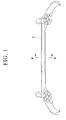
- FIG. 1 shows an axle beam 1 which is one embodiment of a tubular part having a cross section of an irregular shape formed by a method of press-forming the tubular part having a cross section of an irregular shape of the present invention. Additionally, FIG. 2 shows a cross-sectional view taken along the line A-A of FIG. 1 .
- the axle beam 1 is obtained by crushing one steel tube between a pair of upper and lower dies (which will be described later) to press-form a steel tube with a V-shaped cross-section.
- Reference numeral 1a represents an upper plate corresponding to an upper arc in the cross-sectional shape of a steel tube before processing as the axle beam 1
- reference numeral 1b represents a lower plate corresponding to a lower arc in this cross-sectional shape.
- reference numerals 2a and 2b respectively represent the bottom portions of the upper plates 1a and 1b
- reference numerals 2c and 2d respectively represent the V-groove surfaces of the bottom portions 2a and 2b.
- the stress generated during a fatigue test becomes the highest at the V-groove surface 2c of the bottom portion 2a of the upper plate 1a. Therefore, the V-groove surface 2c of the bottom portion 2a of the upper plate 1a is required to have compressive residual stress. Accordingly, in this embodiment, the compressive residual stress is imparted to the V-groove surface 2c of the bottom portion 2a of the member, thereby improving fatigue resistance.
- the press-working conditions for making the residual stress of the V-groove surfaces 2c and 2d of the bottom portion 2 of the axle beam 1 after spring-back into compressive stress i.e., for forming compressive residual stress in the V-groove surfaces 2c and 2d of the bottom portion 2 by spring-back
- the above Formula (1) is a condition required in order to eliminate the gap between the upper die (which will be described later) and an article to be formed when the die arrives at a bottom dead point position. Additionally, as will be described below, R 1 ⁇ 3t is required in order to leave a gap between the die and the given position of a steel tube which is an article to be formed before the upper die arrives at a bottom dead point position. On the other hand, 1.5t ⁇ R 1 is required in order to prevent cracks from initiating during press-forming. For these reasons, it is necessary to satisfy the condition of Formula (2).
- FIGS. 3 to 5 are cross-sectional views of the press-forming process in the bottom portion 2 of the axle beam 1.
- FIGS. 3 to 5 are respectively an enlarged cross-sectional view of the press-forming process before the upper die arrives at its bottom dead point position, an enlarged cross-sectional view of the press-forming process when the upper die has arrived at its bottom dead point position, and an enlarged cross-sectional view of the bottom portion 2 of the axle beam 1 after the upper and lower dies are opened.
- reference numeral 11 represents an upper die and reference numeral 12 represents a lower die.
- reference numeral 12 represents a lower die.
- This embodiment is similar to the conventional technique in that the steel tube which is an article to be formed is set on the lower die 12, and the upper die 11 is lowered to crush the steel tube between the upper die 11 and the lower die 12 to press-form the steel tube into a V-shaped cross-sectional axle beam.
- this embodiment has the following features.
- both the upper plate 1a and the lower plate 1b have general bending deformation in which the curvature radii R 1 and R 2 become small.
- the curvature radii R 1 and R 2 of the upper die 11 and the lower die 12 which form the bottom portion 2 of the V-shaped axle beam 1 are small as limited by Formula (2), the article to be formed is not adapted to the dies, and thereby undergoes excessive bending.
- a gap 3 is formed between the tip 11a of the upper die 11 and the corresponding portion of the upper plate 1a.
- gaps 4 and 4 are also formed between both side portions of the bottom portion 12a of the lower die 12 and the corresponding portions of the lower plate 1b.
- Press-forming proceeds with the gaps 3 and 4 before the upper die 11 arrives at a bottom dead point position.
- the V-groove surface 2c of the bottom portion 2a of the upper plate 1a and the V-groove surface 2d of the bottom portion 2b of the lower plate 1b are in a compressive stress state.
- a die design in which a gap does not remain between the upper and lower dies 11 and 12 and the article to be formed as limited by Formula (1) when the upper die 11 has arrived at a bottom dead point position. Therefore, if forming is continued, deformation is applied which crushes the gap 3 between the tip 11a of the upper die 11 and the corresponding portion of the upper plate 1a and the gaps 4 and 4 between both the side portions of the bottom portion 12a of the lower die 12 and the corresponding portions of the lower plate 1b. That is, in this case, the V-groove surfaces 2c and 2d of the bottom portion 2 are bent back to cause deformation in which the curvature radii R 1 and R 2 become large.
- the bottom portion 2a of the upper plate 1a and the bottom portion 2b of the lower plate 1b are processed so as to be pushed wide by the dies, and eventually the V-groove surfaces 2c and 2d are brought into a tensile stress state. That is, the stress which makes the curvature radii R 1 and R 2 small is generated in both the V-groove surfaces 2c and 2d of the bottom portion 2.
- an axle beam has been shown as an example of a tubular part having a cross section of an irregular shape.
- the present invention can also be widely applied to other underbody parts for a vehicle which require fatigue resistance, such as a suspension part around the axle beam.
- the material of the steel tube is not limited at all, and can be any material. That is, if the press-forming method of the present invention is used, fatigue resistance can be improved for any kind of steel tube material.
- the press-forming method of the present invention if used, a compressive residual stress can be imparted to a portion where the stress to be generated is high. Therefore, fatigue life can be significantly improved.
- the fatigue life is short. Therefore, heat-treatment by quenching or the like is carried out after press-forming, thereby improving the fatigue life.
- the fatigue life can be improved even without heat treatment. Therefore, it is possible to achieve a reduction of the cost of heat treatment and a simplification of the processes. Furthermore, since heat treatment is not required, there is also an advantage that product precision can be secured.
- the steel tube formed using the steel plate having a strength of 780-MPa class was press-formed under different conditions (i.e, t, R 1 , and R 2 ), and a tubular part having a cross section of an irregular shape as shown in FIG. 6 was obtained.
- Numerical values which did not satisfy the conditions of the present invention are underlined in Comparative Example of Table 1. Additionally, the state of the residual stress of the V-groove surfaces 2c and 2d of the bottom portion 2 of the part after press-forming is shown in Table 1.
- a test piece 21 with a width of 20 mm was cut out from a longitudinal central portion of the tubular part having a cross section of a V-shape.
- longitudinal residual stress was released.
- the values of the residual stress of the V-groove surfaces 2c and 2d of the bottom portion 2 of the test piece was not substantially changed before and after cutting. As shown in FIG.
- a fatigue test was performed by holding both ends of the cut-out V-shaped test piece by a fixed-side retainer 22 and a vibration-side retainer 23, and vibrating the vibration-side retainer 23 in a horizontal direction (a direction in which the V-shaped width increases or decreases) shown by the arrow of FIG. 7 at a frequency of 1 Hz by a vibrator 24 so that an alternate stress of ⁇ 500 MPa is applied to the test piece 21.
- the alternate stress cycles to occurrence of cracks caused by this fatigue test is shown in Table 1.
- the alternate stress cycles to occurrence of fatigue cracks was evaluated in three ranks including rank (C) in which the fatigue life was less than 10,000 times, rank (B) in which the fatigue life is greater than or equal to 10,000 times and less than 100,000 times, and rank (A) having an excellent fatigue life of greater than or equal to 100,000 times.
- a method of press-forming a tubular part having a cross section of an irregular shape used as an axle beam or the like, and a tubular part having a cross section of an irregular shape formed by this method can be provided.
Landscapes
- Engineering & Computer Science (AREA)
- Mechanical Engineering (AREA)
- Shaping Metal By Deep-Drawing, Or The Like (AREA)
- Vehicle Body Suspensions (AREA)
Abstract
Description
- The present invention relates to: a press-forming method of a tubular part having a cross section of an irregular shape used for underbody parts, such as an axle beam; and a tubular part having a cross section of an irregular shape formed by this press-forming method, for a vehicle, such as an automobile or track.
- Priority is claimed on Japanese Patent Application No.
2008-124787, filed on May 12, 2008 - Tubular parts having a cross section of an irregular shape are conventionally and widely used as underbody parts for vehicles, such as axle beams disposed between the wheels of the vehicle and their surrounding suspension parts.
- Since the tubular parts having the cross section of the irregular shape repeatedly takes an impact load, a torsional load, and the like while the vehicle is moving, high fatigue resistance is required in addition to high strength. These days, it is required that underbody parts for vehicles, such as axle beams, are not formed using a plurality of parts, but formed by press-working one steel tube.
- An axle beam of a hollow structure formed into a cross section of an irregular shape by press-working of a high-strength steel tube is disclosed in the Japanese Unexamined Patent Application, First Publication No.
2001-321846 - However, in the axle beam of the Japanese Unexamined Patent Application, First Publication No.
2001-321846 - In addition, there are also problems in that the heat treatment deteriorates product precision and makes the attachment operation to the vehicle body difficult.
- The invention was contrived in view of the above situation, and an object thereof is to provide a press-forming method of a tubular part having a cross section of an irregular shape which can improve fatigue resistance without heat treatment, such as quenching, (unlike the conventional techniques) which can reduce the cost and the number of processes, and which can secure product precision to improve attachability to a vehicle body when a tubular part having a cross section of an irregular shape, such as an axle beam, is manufactured by the press-forming of a steel tube, and to provide a tubular part having a cross section of an irregular shape formed by this press-forming method.
- The invention has adopted the followings in order to solve the above-described problems and achieve the object.
- (1) the present invention is a method of press-forming a tubular part having a cross section of an irregular shape which crushes a steel tube between an upper die and a lower die in order to form a V-shaped cross section. When the curvature radius of a tip of the upper die is defined as R1, the curvature radius of a bottom portion of the lower die corresponding to the tip of the upper die is defined as R2, and the wall thickness of the steel tube is defined as t; R1, R2, and t satisfy R1+2t=R2 and 1.5t≤R1≤3t.
- (2) In a method of press-forming a tubular part having a cross section of an irregular shape described in the above (1), the method may include the steps of: performing pressing where a gap is provided between the tip of the upper die and the steel tube and between the bottom portion of the lower die and the steel tube before the upper die arrives at its bottom dead point position; performing pressing to form a tubular part having a cross section of an irregular shape so that the gap is completely crushed when the upper die arrives at the bottom dead point position; and giving compressive residual stress to a V-groove surface in the bottom portion of the tubular part having a cross section of an irregular shape by the spring-back which is caused in the tubular part having a cross section of an irregular shape after the upper and lower dies are opened.
- (3) The present invention is a tubular part having a cross section of an irregular shape formed a V-shaped cross section manufactured by the method of press-forming a tubular part having a cross section of an irregular shape described in the above (2). The V-groove surface of the tubular part having a cross section of an irregular shape has the compressive residual stress formed by the spring-back.
- (4) The tubular part having a cross section of an irregular shape described in the above (3) may be an underbody member used for a vehicle.
- Since the upper and lower dies which satisfy R1+2t=R2 and 1.5t≤R1≤3t are used in the press-forming method of tubular part having a cross section of an irregular shape described in the above (1), the residual stress of the tubular part having the cross section of the irregular shape can be controlled. Consequently, heat treatment, such as quenching, is not required after press-forming, unlike the related art, and compressive residual stress can be imparted to a predetermined position which is apt to sustain fatigue damage only during the pressing step, and thus a high fatigue resistance can be obtained.
- Moreover, since the tubular part having the cross section of the irregular shape described in the above (3) has the compressive residual stress in the V-groove surface of the bottom portion of the part, a high fatigue resistance can be obtained and the product life of the part can be lengthened.
- In particular, if the tubular part having the cross section of the irregular shape of the above (3) is used as an underbody part for a vehicle, it is possible to realize a low cost vehicle with a longer product life.
-
-
FIG. 1 is a perspective view showing an axle beam according to an embodiment of the present invention. -
FIG. 2 is a cross-sectional view taken along the line A-A ofFIG. 1 . -
FIG. 3 is a cross-sectional view showing a state before the upper die arrives at its bottom dead point in the pressing process. -
FIG. 4 is a cross-sectional view showing a state when the upper die has arrived at its bottom dead point position in the pressing process. -
FIG. 5 is a cross-sectional view showing the bottom portion of the axle beam after press-forming. -
FIG. 6 is a perspective view of a fatigue-resistant evaluation test piece of a V groove portion in a V-shaped cross-sectional tubular part. -
FIG. 7 is a drawing showing the test conditions of a fatigue-resistant evaluation test. -
FIG. 8A is a drawing showing the residual stress of a test piece in Examples of the present invention. -
FIG. 8B is a drawing showing the residual stress of test pieces in Comparative Examples 2 to 4. -
FIG. 8C is a drawing showing broken examples of test pieces in Comparative Examples 2 to 4. - Hereinafter, preferred embodiment of the present invention will be described with reference to the accompanying drawings.
-
FIG. 1 shows anaxle beam 1 which is one embodiment of a tubular part having a cross section of an irregular shape formed by a method of press-forming the tubular part having a cross section of an irregular shape of the present invention. Additionally,FIG. 2 shows a cross-sectional view taken along the line A-A ofFIG. 1 . - As shown in
FIG. 2 , theaxle beam 1 is obtained by crushing one steel tube between a pair of upper and lower dies (which will be described later) to press-form a steel tube with a V-shaped cross-section.Reference numeral 1a represents an upper plate corresponding to an upper arc in the cross-sectional shape of a steel tube before processing as theaxle beam 1, andreference numeral 1b represents a lower plate corresponding to a lower arc in this cross-sectional shape. Moreover,reference numerals upper plates reference numerals bottom portions - In the
axle beam 1, the stress generated during a fatigue test becomes the highest at the V-groove surface 2c of thebottom portion 2a of theupper plate 1a. Therefore, the V-groove surface 2c of thebottom portion 2a of theupper plate 1a is required to have compressive residual stress. Accordingly, in this embodiment, the compressive residual stress is imparted to the V-groove surface 2c of thebottom portion 2a of the member, thereby improving fatigue resistance. - In this embodiment, when the press-forming method of crushing a steel tube between a pair of upper and lower dies in order to manufacture a tubular part having a cross section of an irregular shape formed a V-shaped cross-section is performed and when the curvature radius of the tip of the upper die is defined as R1 (mm), the curvature radius of the bottom portion of the lower die corresponding to the tip of the upper die is defined as R2 (mm), and the plate thickness of the steel tube is defined as t (mm), the steel tube is press-formed so that R1, R2, and t satisfy the following Formulas (1) and (2).


- In this embodiment, the press-working conditions for making the residual stress of the V-
groove surfaces bottom portion 2 of theaxle beam 1 after spring-back into compressive stress (i.e., for forming compressive residual stress in the V-groove surfaces bottom portion 2 by spring-back) are specified. - The above Formula (1) is a condition required in order to eliminate the gap between the upper die (which will be described later) and an article to be formed when the die arrives at a bottom dead point position. Additionally, as will be described below, R1≤3t is required in order to leave a gap between the die and the given position of a steel tube which is an article to be formed before the upper die arrives at a bottom dead point position. On the other hand, 1.5t≤R1 is required in order to prevent cracks from initiating during press-forming. For these reasons, it is necessary to satisfy the condition of Formula (2).
- The press-forming process of the present invention will be described below.
- All of
FIGS. 3 to 5 are cross-sectional views of the press-forming process in thebottom portion 2 of theaxle beam 1.FIGS. 3 to 5 are respectively an enlarged cross-sectional view of the press-forming process before the upper die arrives at its bottom dead point position, an enlarged cross-sectional view of the press-forming process when the upper die has arrived at its bottom dead point position, and an enlarged cross-sectional view of thebottom portion 2 of theaxle beam 1 after the upper and lower dies are opened. - In addition, in
FIGS. 3 to 5 ,reference numeral 11 represents an upper die andreference numeral 12 represents a lower die. When the steel tube which is the base material is press-formed between theupper die 11 and thelower die 12, theupper plate 1a and thelower plate 1b are brought into close contact with each other between the dies. - This embodiment is similar to the conventional technique in that the steel tube which is an article to be formed is set on the
lower die 12, and theupper die 11 is lowered to crush the steel tube between theupper die 11 and thelower die 12 to press-form the steel tube into a V-shaped cross-sectional axle beam. However, this embodiment has the following features. - As shown in
FIG. 3 , in the press-forming process before theupper die 11 arrives at a bottom dead point position, both theupper plate 1a and thelower plate 1b have general bending deformation in which the curvature radii R1 and R2 become small. However, since the curvature radii R1 and R2 of theupper die 11 and thelower die 12 which form thebottom portion 2 of the V-shaped axle beam 1 are small as limited by Formula (2), the article to be formed is not adapted to the dies, and thereby undergoes excessive bending. As a result, agap 3 is formed between thetip 11a of theupper die 11 and the corresponding portion of theupper plate 1a. Similarly, gaps 4 and 4 are also formed between both side portions of thebottom portion 12a of thelower die 12 and the corresponding portions of thelower plate 1b. - Press-forming proceeds with the
gaps 3 and 4 before theupper die 11 arrives at a bottom dead point position. In this state, the V-groove surface 2c of thebottom portion 2a of theupper plate 1a and the V-groove surface 2d of thebottom portion 2b of thelower plate 1b are in a compressive stress state. - Additionally, as shown in
FIG. 4 , there is provided a die design in which a gap does not remain between the upper and lower dies 11 and 12 and the article to be formed as limited by Formula (1) when theupper die 11 has arrived at a bottom dead point position. Therefore, if forming is continued, deformation is applied which crushes thegap 3 between thetip 11a of theupper die 11 and the corresponding portion of theupper plate 1a and the gaps 4 and 4 between both the side portions of thebottom portion 12a of thelower die 12 and the corresponding portions of thelower plate 1b. That is, in this case, the V-groove surfaces bottom portion 2 are bent back to cause deformation in which the curvature radii R1 and R2 become large. - In this state, the
bottom portion 2a of theupper plate 1a and thebottom portion 2b of thelower plate 1b are processed so as to be pushed wide by the dies, and eventually the V-groove surfaces groove surfaces bottom portion 2. - Finally, as shown in
FIG. 5 , when theupper die 11 is raised and the article to be formed is released from the dies, the spring-back which makes the curvature radii R1 and R2 small occurs due to the reaction of the process of increasing the curvature radii R1 and R2 of the V-groove surfaces bottom portion 2 when theupper die 11 arrives at a bottom dead point position. As a result, a compressive residual stress is imparted to the V-groove surfaces bottom portion 2 of the axle beam by the spring-back after press-forming. - In the aforementioned embodiment, an axle beam has been shown as an example of a tubular part having a cross section of an irregular shape. However, it is natural that the present invention can also be widely applied to other underbody parts for a vehicle which require fatigue resistance, such as a suspension part around the axle beam. Additionally, the material of the steel tube is not limited at all, and can be any material. That is, if the press-forming method of the present invention is used, fatigue resistance can be improved for any kind of steel tube material.
- As is clear from the above description, if the press-forming method of the present invention is used, a compressive residual stress can be imparted to a portion where the stress to be generated is high. Therefore, fatigue life can be significantly improved. In the conventional method, the fatigue life is short. Therefore, heat-treatment by quenching or the like is carried out after press-forming, thereby improving the fatigue life. In the present invention, the fatigue life can be improved even without heat treatment. Therefore, it is possible to achieve a reduction of the cost of heat treatment and a simplification of the processes. Furthermore, since heat treatment is not required, there is also an advantage that product precision can be secured.
- As shown in Table 1, the steel tube formed using the steel plate having a strength of 780-MPa class was press-formed under different conditions (i.e, t, R1, and R2), and a tubular part having a cross section of an irregular shape as shown in
FIG. 6 was obtained. Numerical values which did not satisfy the conditions of the present invention are underlined in Comparative Example of Table 1. Additionally, the state of the residual stress of the V-groove surfaces bottom portion 2 of the part after press-forming is shown in Table 1. - In order to evaluate the fatigue resistance of the
bottom portion 2 of the tubular part, as shown inFIG. 6 , atest piece 21 with a width of 20 mm was cut out from a longitudinal central portion of the tubular part having a cross section of a V-shape. When thetest piece 21 was cut out, longitudinal residual stress was released. However, since circumferential constraint was maintained, the values of the residual stress of the V-groove surfaces bottom portion 2 of the test piece was not substantially changed before and after cutting. As shown inFIG. 7 , a fatigue test was performed by holding both ends of the cut-out V-shaped test piece by a fixed-side retainer 22 and a vibration-side retainer 23, and vibrating the vibration-side retainer 23 in a horizontal direction (a direction in which the V-shaped width increases or decreases) shown by the arrow ofFIG. 7 at a frequency of 1 Hz by avibrator 24 so that an alternate stress of ±500 MPa is applied to thetest piece 21. The alternate stress cycles to occurrence of cracks caused by this fatigue test is shown in Table 1. Here, the alternate stress cycles to occurrence of fatigue cracks was evaluated in three ranks including rank (C) in which the fatigue life was less than 10,000 times, rank (B) in which the fatigue life is greater than or equal to 10,000 times and less than 100,000 times, and rank (A) having an excellent fatigue life of greater than or equal to 100,000 times. - As is clear from Examples 1 to 3, in the tubular part having a cross section of an irregular shape of the present invention, as shown in
FIG. 8A , it was confirmed that sufficient compressive residual stress was imparted to the V-groove surfaces bottom portion 2 and fatigue resistance was significantly improved. - As Comparative Example 1, a case where the curvature radius R1 was smaller than that of Formula (2) is shown. In this case, since the curvature radius R1 was too small, a crack was generated at the
bottom portion 2 during forming, and forming could not be performed. - As Comparative Example 2, a case where the curvature radius R1 was larger than that of Formula (2) is shown. In this case, since the curvature radius R1 was too large, the article to be formed was formed in close contact with the dies without any gap therebetween during the pressing process. Therefore, when the
upper die 11 reached a bottom dead point position, thebottom portion 2 is not bent back, and thereby the V-groove surface 2c of thebottom portion 2a of theupper plate 1a was under compressive stress. Therefore, the subsequent spring-back caused tensile residual stress as shown inFIG. 8B in the V-groove surface 2c, and fatigue resistance was reduced. As a result, acrack 30 as shown inFIG. 8C was generated in the V-groove surface 2c of thebottom portion 2a of theupper plate 1a too quickly for practical use. - As Comparative Examples 3 and 4, a case where the curvature radius R2 did not satisfy Formula (1) is shown. Since the curvature radius R2 did not satisfy Formula (1), when the
upper die 11 had arrived at a bottom dead point position, one or more gaps remained between the article to be formed and the dies. Therefore, thebottom portion 2 was not sufficiently bent back, and the V-groove surface 2c of thebottom portion 2a of theupper plate 1a was under compressive stress. Therefore, the subsequent spring-back caused tensile residual stress as shown inFIG. 8B in the V-groove surface 2c, and fatigue resistance was reduced. As a result, acrack 30 as shown inFIG. 8C was generated in the V-groove surface 2c of thebottom portion 2a of theupper plate 1a within an insufficiently short time for practical use. - As described above, in Comparative Examples in which the conditions of the present invention were not satisfied, a crack was generated during working of the
bottom portion 2, or tensile residual stress was caused in the V-groove surface 2c of thebottom portion 2a of theupper plate 1a. Therefore, sufficient fatigue resistance could not be obtained. - It was proven from the above results that the tubular part having a cross section of an irregular shape manufactured by press-forming of a steel tube under conditions of the present invention had an excellent fatigue resistance since a sufficient compressive residual stress was imparted.
Table 1 t R1 R2 Residual Stress of V-groove Surfaces Alternate Stress Cycles to Occurrence of Fatigue Cracks Description Example 1 4 8 16 Compression A Sufficient compressive stress was given, and fatigue resistance was improved, Example 2 4 10 18 Compression A Sufficient compressive stress was given, and fatigue resistance was improved. Example 3 3 5 11 Compression A Sufficient compressive stress was given, and fatigue resistance was improved. Comparative Example 1 4 5 13 Forming could not be performed. Since R1 was too small, a crack was generated at the V-groove surface during forming, and forming could not be performed. Comparative Example 2 4 15 23 Tensile C Since R1 was large, tensile residual stress was generated in the V-groove surface, and fatigue resistance was reduced. Comparative Example 3 4 8 14 Tensile C Since R2 was small, tensile residual stress was generated in the V-groove surface, and fatigue resistance was reduced. Comparative Example 4 4 8 18 Tensile C Since R2 was large, tensile residual stress was generated in the V-groove surface, and fatigue resistance was reduced. Columns beyond the scope of this invention is underlined.
In alternate stress cycles to occurrence of fatigue cracks, rank A was greater than or equal to 100,000 times, and rank C was less than 10,000 times. - While preferred embodiments of the present invention have been described and illustrated above, these are exemplary of the present invention and are not to be considered as limiting. Additions, omissions, substitutions, and other modifications can be made without departing from the scope of the present invention. Accordingly, the present invention is not to be considered as limited by the foregoing description and is only limited by the scope of the appended claims.
- A method of press-forming a tubular part having a cross section of an irregular shape used as an axle beam or the like, and a tubular part having a cross section of an irregular shape formed by this method can be provided.
Claims (4)
- A method of press-forming a tubular part having a cross section of an irregular shape which crushes a steel tube between an upper die and a lower die in order to form a V-shaped cross section,
wherein when the curvature radius of a tip of the upper die is defined as R1, the curvature radius of a bottom portion of the lower die corresponding to the tip of the upper die is defined as R2, and the wall thickness of the steel tube is defined as t; R1, R2, and t satisfy R1+2t=R2 and 1.5t≤R1≤3t. - The method of press-forming a tubular part having a cross section of an irregular shape according to claim 1, the method comprising the steps of:pressing the steel tube in a state in which a gap is provided between the tip of the upper die and the steel tube and between the bottom portion of the lower die and the steel tube, before the upper die arrives at a bottom dead point position thereof;pressing to form a tubular part having a cross section of an irregular shape so that the gap is completely crushed when the upper die arrives at the bottom dead point position; andimparting compressive residual stress to a V-groove surface in the bottom portion of the tubular part having a cross section of an irregular shape by a spring-back which is caused in the tubular part having a cross section of an irregular shape after the upper and lower dies are opened.
- A tubular part having a cross section of an irregular shape formed a V-shaped cross section manufactured by the method of press-forming a tubular part having a cross section of an irregular shape according to claim 2,
wherein the V-groove surface of the tubular part having a cross section of an irregular shape has the compressive residual stress formed by the spring-back. - The tubular part having a cross section of an irregular shape according to claim 3 being an underbody member used for a vehicle.
Applications Claiming Priority (2)
| Application Number | Priority Date | Filing Date | Title |
|---|---|---|---|
| JP2008124787A JP2009274077A (en) | 2008-05-12 | 2008-05-12 | Method of press-forming tubular member having special-shaped cross section and tubular member having special-shaped cross section formed by the same method |
| PCT/JP2009/058832 WO2009139379A1 (en) | 2008-05-12 | 2009-05-12 | Method of press-forming tubular member having irregular cross-sectional shape, and tubular member having irregular cross-sectional shape, formed by the press-forming method |
Publications (3)
| Publication Number | Publication Date |
|---|---|
| EP2298465A1 true EP2298465A1 (en) | 2011-03-23 |
| EP2298465A4 EP2298465A4 (en) | 2015-09-16 |
| EP2298465B1 EP2298465B1 (en) | 2018-09-26 |
Family
ID=41318746
Family Applications (1)
| Application Number | Title | Priority Date | Filing Date |
|---|---|---|---|
| EP09746585.0A Not-in-force EP2298465B1 (en) | 2008-05-12 | 2009-05-12 | Press-forming method of tubular part having cross-section of irregular shape |
Country Status (6)
| Country | Link |
|---|---|
| US (1) | US8894080B2 (en) |
| EP (1) | EP2298465B1 (en) |
| JP (1) | JP2009274077A (en) |
| KR (1) | KR101177219B1 (en) |
| CN (1) | CN101980804B (en) |
| WO (1) | WO2009139379A1 (en) |
Cited By (1)
| Publication number | Priority date | Publication date | Assignee | Title |
|---|---|---|---|---|
| EP2899290A4 (en) * | 2012-09-20 | 2016-03-30 | Nippon Steel & Sumitomo Metal Corp | CURED STEEL PIPE ELEMENT, MOTOR AXLE BEAM USING THE CURED STEEL PIPE ELEMENT, AND METHOD FOR MANUFACTURING THE CURED STEEL PIPE ELEMENT |
Families Citing this family (14)
| Publication number | Priority date | Publication date | Assignee | Title |
|---|---|---|---|---|
| ITTO20080521A1 (en) * | 2008-07-08 | 2010-01-08 | Sistemi Sospensioni Spa | CROSSBEAM FOR A REAR BRIDGE SUSPENSION WITH TORCH FOR MOTOR VEHICLES AND PROCEDURE FOR ITS MANUFACTURING |
| JP2011006781A (en) * | 2009-05-25 | 2011-01-13 | Nippon Steel Corp | Automobile undercarriage component having excellent low cycle fatigue property and method for producing the same |
| FR2950000B1 (en) * | 2009-09-17 | 2011-09-30 | Renault Sa | CLOSED PROFILE JOINT FOR REAR AXLE OF A MOTOR VEHICLE |
| JP2015066572A (en) * | 2013-09-27 | 2015-04-13 | 株式会社神戸製鋼所 | Apparatus and method for manufacturing suspension arm for motor vehicle |
| JP6066896B2 (en) * | 2013-12-17 | 2017-01-25 | 日新製鋼株式会社 | Molding material manufacturing method |
| DE102014109680A1 (en) * | 2014-07-10 | 2016-01-14 | Benteler Automobiltechnik Gmbh | Method for producing a torsion profile from a board and torsion profile |
| WO2017169733A1 (en) * | 2016-03-30 | 2017-10-05 | 新日鐵住金株式会社 | Torsion beam manufacturing method and torsion beam manufacturing device |
| CN109070676B (en) | 2016-05-10 | 2022-03-01 | 日本制铁株式会社 | Torsion beam manufacturing method, torsion beam manufacturing apparatus, and torsion beam |
| DE102018100989B3 (en) | 2018-01-17 | 2019-02-14 | Benteler Automobiltechnik Gmbh | Method for producing a bent torsion profile and torsion profile |
| JP2021126949A (en) * | 2020-02-12 | 2021-09-02 | 株式会社エフテック | Torsion beam |
| EP3971442B1 (en) * | 2020-05-15 | 2025-07-09 | Mitsubishi Steel Mfg. Co., Ltd. | Hollow spring and manufacturing method therefor |
| MX2024011307A (en) * | 2022-06-01 | 2024-09-30 | Nippon Steel Corp | Torsion beam. |
| EP4729316A1 (en) * | 2023-06-14 | 2026-04-22 | Nippon Steel Corporation | Structural component |
| EP4714689A1 (en) * | 2023-06-14 | 2026-03-25 | Nippon Steel Corporation | Structural component |
Family Cites Families (21)
| Publication number | Priority date | Publication date | Assignee | Title |
|---|---|---|---|---|
| FR2031867A5 (en) * | 1969-02-11 | 1970-11-20 | Faure Bertrand Ets | |
| US5409255A (en) * | 1990-08-10 | 1995-04-25 | Benteler Industries, Inc. | Twist beam axle |
| CN1088143A (en) | 1992-12-14 | 1994-06-22 | 欣业企业股份有限公司 | The manufacture method of inward concave iron specials |
| JPH08206741A (en) | 1995-02-01 | 1996-08-13 | Mitsubishi Alum Co Ltd | Cylindrical member for vehicle body structure and bending method thereof |
| DE19653959C1 (en) * | 1996-12-21 | 1998-02-05 | Benteler Werke Ag | Cross-bearer forming indirect component part of compound steering shaft |
| DE19820415C1 (en) | 1998-05-07 | 1999-09-16 | Benteler Werke Ag | Method of forming vehicle axle tube into U-shaped profile |
| DE19941993C1 (en) * | 1999-09-02 | 2000-12-14 | Benteler Werke Ag | Tubular profile manufacturing method for passenger vehicle rear axle uses cold-forming of central part of round cross-section steel tube before localised heating and hardening in water |
| JP3750521B2 (en) | 2000-03-09 | 2006-03-01 | トヨタ自動車株式会社 | Method of manufacturing modified cross-section cylindrical body and axle beam for torsion beam |
| CZ296802B6 (en) * | 2000-05-31 | 2006-06-14 | Benteler Ag | Twist-beam axle with transverse torsion bar |
| US7377041B2 (en) * | 2003-06-18 | 2008-05-27 | Donghee Industrial Co., Ltd. | Torsion beam type suspension, method for forming torsion beam, and apparatus for forming torsion beam |
| JP4211667B2 (en) | 2004-04-21 | 2009-01-21 | トヨタ自動車株式会社 | Torsion beam suspension system |
| CN100441334C (en) * | 2004-04-21 | 2008-12-10 | 渤海船舶重工有限责任公司 | Double-curvature plate cold press forming method and device |
| KR100554310B1 (en) | 2004-09-21 | 2006-02-24 | 주식회사화신 | Beam manufacturing apparatus of torsion beam for automobile rear suspension |
| JP2007076410A (en) | 2005-09-12 | 2007-03-29 | Nippon Steel Corp | Closed section member for automobiles with excellent torsional fatigue characteristics |
| JP2007237784A (en) * | 2006-03-06 | 2007-09-20 | Futaba Industrial Co Ltd | Method for manufacturing torsion beam type suspension |
| JP2008030513A (en) | 2006-07-26 | 2008-02-14 | Toyota Tsusho Corp | Torsion beam, torsion beam type suspension, and method for manufacturing torsion beam |
| JP4201809B2 (en) | 2006-11-13 | 2008-12-24 | 三洋電機株式会社 | Camera shake correction apparatus and method, and imaging apparatus |
| CN101024236A (en) | 2007-02-06 | 2007-08-29 | 南京美奇科技发展有限公司 | Internal high-pressure formation method of special-shape-section pipelike parts |
| KR20090009547A (en) * | 2007-07-20 | 2009-01-23 | 현대자동차주식회사 | Torsion beam of vehicle suspension |
| KR100958977B1 (en) * | 2007-07-25 | 2010-05-20 | 주식회사 포스코 | Tubular torsion beam for rear wheel suspension of automobile and manufacturing method thereof |
| JP4858624B2 (en) * | 2009-04-01 | 2012-01-18 | Jfeスチール株式会社 | Torsion beam manufacturing method and torsion beam |
-
2008
- 2008-05-12 JP JP2008124787A patent/JP2009274077A/en not_active Withdrawn
-
2009
- 2009-05-12 US US12/736,756 patent/US8894080B2/en active Active
- 2009-05-12 KR KR1020107021850A patent/KR101177219B1/en not_active Expired - Fee Related
- 2009-05-12 CN CN200980111571.XA patent/CN101980804B/en active Active
- 2009-05-12 EP EP09746585.0A patent/EP2298465B1/en not_active Not-in-force
- 2009-05-12 WO PCT/JP2009/058832 patent/WO2009139379A1/en not_active Ceased
Non-Patent Citations (1)
| Title |
|---|
| See references of WO2009139379A1 * |
Cited By (2)
| Publication number | Priority date | Publication date | Assignee | Title |
|---|---|---|---|---|
| EP2899290A4 (en) * | 2012-09-20 | 2016-03-30 | Nippon Steel & Sumitomo Metal Corp | CURED STEEL PIPE ELEMENT, MOTOR AXLE BEAM USING THE CURED STEEL PIPE ELEMENT, AND METHOD FOR MANUFACTURING THE CURED STEEL PIPE ELEMENT |
| US9702019B2 (en) | 2012-09-20 | 2017-07-11 | Nippon Steel & Sumitomo Metal Corporation | Quenched steel pipe member, vehicle axle beam using quenched steel pipe member, and method for manufacturing quenched steel pipe member |
Also Published As
| Publication number | Publication date |
|---|---|
| US8894080B2 (en) | 2014-11-25 |
| KR101177219B1 (en) | 2012-08-24 |
| CN101980804B (en) | 2014-06-18 |
| KR20100123749A (en) | 2010-11-24 |
| EP2298465A4 (en) | 2015-09-16 |
| WO2009139379A1 (en) | 2009-11-19 |
| EP2298465B1 (en) | 2018-09-26 |
| CN101980804A (en) | 2011-02-23 |
| US20110121639A1 (en) | 2011-05-26 |
| JP2009274077A (en) | 2009-11-26 |
Similar Documents
| Publication | Publication Date | Title |
|---|---|---|
| EP2298465B1 (en) | Press-forming method of tubular part having cross-section of irregular shape | |
| EP3939712B1 (en) | Pressed component manufacturing method | |
| EP3842164B1 (en) | Press forming method | |
| JP7318602B2 (en) | METHOD FOR MANUFACTURE OF TEST SPECIMEN AND METHOD FOR EVALUATION OF DELAYED FRACTURE CHARACTERISTICS OF HIGH-STRENGTH STEEL STEEL | |
| KR102930787B1 (en) | Shape change prediction method of press formed part | |
| KR20210132158A (en) | Blanks and structural members | |
| KR20180126548A (en) | Torsion beam manufacturing method, torsion beam manufacturing apparatus and torsion beam | |
| EP1512471B1 (en) | Reinforced member | |
| CN111570687B (en) | Forging process of sliding frame | |
| EP3915694B1 (en) | Press molding method and press machine | |
| JP7251605B1 (en) | METHOD FOR SUPPRESSING FATIGUE CRACK PROGRESSION OF BENDED METAL PLATE AND AUTOMOBILE PARTS | |
| JP7205601B1 (en) | METHOD FOR SUPPRESSING FATIGUE CRACK PROGRESSION OF BENDED METAL PLATE AND AUTOMOBILE PARTS | |
| CN115379908B (en) | Method for manufacturing pressed part, method for manufacturing blank, and steel plate | |
| CN110548789B (en) | Press forming method and press forming apparatus | |
| JP4684862B2 (en) | Bolt forging method | |
| JP7266716B2 (en) | Hollow spring manufacturing method | |
| EP3278896B1 (en) | Press-formed product and method for designing the same | |
| JP2829396B2 (en) | Leaf spring for vehicles | |
| KR100611405B1 (en) | Tailored blank material for press molding excellent in formability and its manufacturing method | |
| RU2227812C2 (en) | Method of manufacture of spring articles | |
| KR20260027424A (en) | Manufacturing method of vehicle parts | |
| JP2023049487A (en) | Production method for suspension part | |
| JP2020025964A (en) | Manufacturing method of molded products | |
| JPH06246338A (en) | Production of large die for extruding light alloy and the like | |
| JP2006224122A (en) | Thin steel sheet blank with excellent punch end face formability and fatigue characteristics |
Legal Events
| Date | Code | Title | Description |
|---|---|---|---|
| PUAI | Public reference made under article 153(3) epc to a published international application that has entered the european phase |
Free format text: ORIGINAL CODE: 0009012 |
|
| 17P | Request for examination filed |
Effective date: 20101208 |
|
| AK | Designated contracting states |
Kind code of ref document: A1 Designated state(s): AT BE BG CH CY CZ DE DK EE ES FI FR GB GR HR HU IE IS IT LI LT LU LV MC MK MT NL NO PL PT RO SE SI SK TR |
|
| AX | Request for extension of the european patent |
Extension state: AL BA RS |
|
| DAX | Request for extension of the european patent (deleted) | ||
| RAP1 | Party data changed (applicant data changed or rights of an application transferred) |
Owner name: NIPPON STEEL & SUMITOMO METAL CORPORATION |
|
| RA4 | Supplementary search report drawn up and despatched (corrected) |
Effective date: 20150818 |
|
| RIC1 | Information provided on ipc code assigned before grant |
Ipc: B21D 22/02 20060101AFI20150812BHEP Ipc: B21D 53/88 20060101ALI20150812BHEP Ipc: B60G 9/04 20060101ALI20150812BHEP |
|
| 17Q | First examination report despatched |
Effective date: 20160701 |
|
| GRAP | Despatch of communication of intention to grant a patent |
Free format text: ORIGINAL CODE: EPIDOSNIGR1 |
|
| STAA | Information on the status of an ep patent application or granted ep patent |
Free format text: STATUS: GRANT OF PATENT IS INTENDED |
|
| INTG | Intention to grant announced |
Effective date: 20180425 |
|
| GRAS | Grant fee paid |
Free format text: ORIGINAL CODE: EPIDOSNIGR3 |
|
| GRAA | (expected) grant |
Free format text: ORIGINAL CODE: 0009210 |
|
| STAA | Information on the status of an ep patent application or granted ep patent |
Free format text: STATUS: THE PATENT HAS BEEN GRANTED |
|
| AK | Designated contracting states |
Kind code of ref document: B1 Designated state(s): AT BE BG CH CY CZ DE DK EE ES FI FR GB GR HR HU IE IS IT LI LT LU LV MC MK MT NL NO PL PT RO SE SI SK TR |
|
| REG | Reference to a national code |
Ref country code: GB Ref legal event code: FG4D |
|
| REG | Reference to a national code |
Ref country code: CH Ref legal event code: EP |
|
| REG | Reference to a national code |
Ref country code: AT Ref legal event code: REF Ref document number: 1045382 Country of ref document: AT Kind code of ref document: T Effective date: 20181015 |
|
| REG | Reference to a national code |
Ref country code: IE Ref legal event code: FG4D |
|
| REG | Reference to a national code |
Ref country code: DE Ref legal event code: R096 Ref document number: 602009054746 Country of ref document: DE |
|
| REG | Reference to a national code |
Ref country code: NL Ref legal event code: MP Effective date: 20180926 |
|
| PG25 | Lapsed in a contracting state [announced via postgrant information from national office to epo] |
Ref country code: FI Free format text: LAPSE BECAUSE OF FAILURE TO SUBMIT A TRANSLATION OF THE DESCRIPTION OR TO PAY THE FEE WITHIN THE PRESCRIBED TIME-LIMIT Effective date: 20180926 Ref country code: LT Free format text: LAPSE BECAUSE OF FAILURE TO SUBMIT A TRANSLATION OF THE DESCRIPTION OR TO PAY THE FEE WITHIN THE PRESCRIBED TIME-LIMIT Effective date: 20180926 Ref country code: SE Free format text: LAPSE BECAUSE OF FAILURE TO SUBMIT A TRANSLATION OF THE DESCRIPTION OR TO PAY THE FEE WITHIN THE PRESCRIBED TIME-LIMIT Effective date: 20180926 Ref country code: NO Free format text: LAPSE BECAUSE OF FAILURE TO SUBMIT A TRANSLATION OF THE DESCRIPTION OR TO PAY THE FEE WITHIN THE PRESCRIBED TIME-LIMIT Effective date: 20181226 Ref country code: GR Free format text: LAPSE BECAUSE OF FAILURE TO SUBMIT A TRANSLATION OF THE DESCRIPTION OR TO PAY THE FEE WITHIN THE PRESCRIBED TIME-LIMIT Effective date: 20181227 Ref country code: BG Free format text: LAPSE BECAUSE OF FAILURE TO SUBMIT A TRANSLATION OF THE DESCRIPTION OR TO PAY THE FEE WITHIN THE PRESCRIBED TIME-LIMIT Effective date: 20181226 |
|
| REG | Reference to a national code |
Ref country code: LT Ref legal event code: MG4D |
|
| PG25 | Lapsed in a contracting state [announced via postgrant information from national office to epo] |
Ref country code: HR Free format text: LAPSE BECAUSE OF FAILURE TO SUBMIT A TRANSLATION OF THE DESCRIPTION OR TO PAY THE FEE WITHIN THE PRESCRIBED TIME-LIMIT Effective date: 20180926 Ref country code: LV Free format text: LAPSE BECAUSE OF FAILURE TO SUBMIT A TRANSLATION OF THE DESCRIPTION OR TO PAY THE FEE WITHIN THE PRESCRIBED TIME-LIMIT Effective date: 20180926 |
|
| REG | Reference to a national code |
Ref country code: AT Ref legal event code: MK05 Ref document number: 1045382 Country of ref document: AT Kind code of ref document: T Effective date: 20180926 |
|
| PG25 | Lapsed in a contracting state [announced via postgrant information from national office to epo] |
Ref country code: AT Free format text: LAPSE BECAUSE OF FAILURE TO SUBMIT A TRANSLATION OF THE DESCRIPTION OR TO PAY THE FEE WITHIN THE PRESCRIBED TIME-LIMIT Effective date: 20180926 Ref country code: ES Free format text: LAPSE BECAUSE OF FAILURE TO SUBMIT A TRANSLATION OF THE DESCRIPTION OR TO PAY THE FEE WITHIN THE PRESCRIBED TIME-LIMIT Effective date: 20180926 Ref country code: CZ Free format text: LAPSE BECAUSE OF FAILURE TO SUBMIT A TRANSLATION OF THE DESCRIPTION OR TO PAY THE FEE WITHIN THE PRESCRIBED TIME-LIMIT Effective date: 20180926 Ref country code: NL Free format text: LAPSE BECAUSE OF FAILURE TO SUBMIT A TRANSLATION OF THE DESCRIPTION OR TO PAY THE FEE WITHIN THE PRESCRIBED TIME-LIMIT Effective date: 20180926 Ref country code: RO Free format text: LAPSE BECAUSE OF FAILURE TO SUBMIT A TRANSLATION OF THE DESCRIPTION OR TO PAY THE FEE WITHIN THE PRESCRIBED TIME-LIMIT Effective date: 20180926 Ref country code: EE Free format text: LAPSE BECAUSE OF FAILURE TO SUBMIT A TRANSLATION OF THE DESCRIPTION OR TO PAY THE FEE WITHIN THE PRESCRIBED TIME-LIMIT Effective date: 20180926 Ref country code: PL Free format text: LAPSE BECAUSE OF FAILURE TO SUBMIT A TRANSLATION OF THE DESCRIPTION OR TO PAY THE FEE WITHIN THE PRESCRIBED TIME-LIMIT Effective date: 20180926 Ref country code: IS Free format text: LAPSE BECAUSE OF FAILURE TO SUBMIT A TRANSLATION OF THE DESCRIPTION OR TO PAY THE FEE WITHIN THE PRESCRIBED TIME-LIMIT Effective date: 20190126 |
|
| PG25 | Lapsed in a contracting state [announced via postgrant information from national office to epo] |
Ref country code: PT Free format text: LAPSE BECAUSE OF FAILURE TO SUBMIT A TRANSLATION OF THE DESCRIPTION OR TO PAY THE FEE WITHIN THE PRESCRIBED TIME-LIMIT Effective date: 20190126 Ref country code: SK Free format text: LAPSE BECAUSE OF FAILURE TO SUBMIT A TRANSLATION OF THE DESCRIPTION OR TO PAY THE FEE WITHIN THE PRESCRIBED TIME-LIMIT Effective date: 20180926 |
|
| REG | Reference to a national code |
Ref country code: DE Ref legal event code: R082 Ref document number: 602009054746 Country of ref document: DE Representative=s name: VOSSIUS & PARTNER PATENTANWAELTE RECHTSANWAELT, DE Ref country code: DE Ref legal event code: R081 Ref document number: 602009054746 Country of ref document: DE Owner name: NIPPON STEEL CORPORATION, JP Free format text: FORMER OWNER: NIPPON STEEL & SUMITOMO METAL CORPORATION, TOKYO, JP |
|
| REG | Reference to a national code |
Ref country code: DE Ref legal event code: R097 Ref document number: 602009054746 Country of ref document: DE |
|
| PG25 | Lapsed in a contracting state [announced via postgrant information from national office to epo] |
Ref country code: DK Free format text: LAPSE BECAUSE OF FAILURE TO SUBMIT A TRANSLATION OF THE DESCRIPTION OR TO PAY THE FEE WITHIN THE PRESCRIBED TIME-LIMIT Effective date: 20180926 |
|
| PLBE | No opposition filed within time limit |
Free format text: ORIGINAL CODE: 0009261 |
|
| STAA | Information on the status of an ep patent application or granted ep patent |
Free format text: STATUS: NO OPPOSITION FILED WITHIN TIME LIMIT |
|
| 26N | No opposition filed |
Effective date: 20190627 |
|
| PG25 | Lapsed in a contracting state [announced via postgrant information from national office to epo] |
Ref country code: SI Free format text: LAPSE BECAUSE OF FAILURE TO SUBMIT A TRANSLATION OF THE DESCRIPTION OR TO PAY THE FEE WITHIN THE PRESCRIBED TIME-LIMIT Effective date: 20180926 |
|
| REG | Reference to a national code |
Ref country code: CH Ref legal event code: PL |
|
| PG25 | Lapsed in a contracting state [announced via postgrant information from national office to epo] |
Ref country code: CH Free format text: LAPSE BECAUSE OF NON-PAYMENT OF DUE FEES Effective date: 20190531 Ref country code: LI Free format text: LAPSE BECAUSE OF NON-PAYMENT OF DUE FEES Effective date: 20190531 Ref country code: MC Free format text: LAPSE BECAUSE OF FAILURE TO SUBMIT A TRANSLATION OF THE DESCRIPTION OR TO PAY THE FEE WITHIN THE PRESCRIBED TIME-LIMIT Effective date: 20180926 |
|
| REG | Reference to a national code |
Ref country code: BE Ref legal event code: MM Effective date: 20190531 |
|
| PG25 | Lapsed in a contracting state [announced via postgrant information from national office to epo] |
Ref country code: LU Free format text: LAPSE BECAUSE OF NON-PAYMENT OF DUE FEES Effective date: 20190512 |
|
| PG25 | Lapsed in a contracting state [announced via postgrant information from national office to epo] |
Ref country code: TR Free format text: LAPSE BECAUSE OF FAILURE TO SUBMIT A TRANSLATION OF THE DESCRIPTION OR TO PAY THE FEE WITHIN THE PRESCRIBED TIME-LIMIT Effective date: 20180926 |
|
| PG25 | Lapsed in a contracting state [announced via postgrant information from national office to epo] |
Ref country code: IE Free format text: LAPSE BECAUSE OF NON-PAYMENT OF DUE FEES Effective date: 20190512 |
|
| PG25 | Lapsed in a contracting state [announced via postgrant information from national office to epo] |
Ref country code: BE Free format text: LAPSE BECAUSE OF NON-PAYMENT OF DUE FEES Effective date: 20190531 |
|
| PGFP | Annual fee paid to national office [announced via postgrant information from national office to epo] |
Ref country code: DE Payment date: 20200428 Year of fee payment: 12 Ref country code: FR Payment date: 20200414 Year of fee payment: 12 |
|
| PGFP | Annual fee paid to national office [announced via postgrant information from national office to epo] |
Ref country code: IT Payment date: 20200414 Year of fee payment: 12 Ref country code: GB Payment date: 20200430 Year of fee payment: 12 |
|
| PG25 | Lapsed in a contracting state [announced via postgrant information from national office to epo] |
Ref country code: CY Free format text: LAPSE BECAUSE OF FAILURE TO SUBMIT A TRANSLATION OF THE DESCRIPTION OR TO PAY THE FEE WITHIN THE PRESCRIBED TIME-LIMIT Effective date: 20180926 |
|
| PG25 | Lapsed in a contracting state [announced via postgrant information from national office to epo] |
Ref country code: HU Free format text: LAPSE BECAUSE OF FAILURE TO SUBMIT A TRANSLATION OF THE DESCRIPTION OR TO PAY THE FEE WITHIN THE PRESCRIBED TIME-LIMIT; INVALID AB INITIO Effective date: 20090512 Ref country code: MT Free format text: LAPSE BECAUSE OF FAILURE TO SUBMIT A TRANSLATION OF THE DESCRIPTION OR TO PAY THE FEE WITHIN THE PRESCRIBED TIME-LIMIT Effective date: 20180926 |
|
| REG | Reference to a national code |
Ref country code: DE Ref legal event code: R119 Ref document number: 602009054746 Country of ref document: DE |
|
| GBPC | Gb: european patent ceased through non-payment of renewal fee |
Effective date: 20210512 |
|
| PG25 | Lapsed in a contracting state [announced via postgrant information from national office to epo] |
Ref country code: GB Free format text: LAPSE BECAUSE OF NON-PAYMENT OF DUE FEES Effective date: 20210512 Ref country code: DE Free format text: LAPSE BECAUSE OF NON-PAYMENT OF DUE FEES Effective date: 20211201 |
|
| PG25 | Lapsed in a contracting state [announced via postgrant information from national office to epo] |
Ref country code: FR Free format text: LAPSE BECAUSE OF NON-PAYMENT OF DUE FEES Effective date: 20210531 |
|
| PG25 | Lapsed in a contracting state [announced via postgrant information from national office to epo] |
Ref country code: MK Free format text: LAPSE BECAUSE OF FAILURE TO SUBMIT A TRANSLATION OF THE DESCRIPTION OR TO PAY THE FEE WITHIN THE PRESCRIBED TIME-LIMIT Effective date: 20180926 |
|
| PG25 | Lapsed in a contracting state [announced via postgrant information from national office to epo] |
Ref country code: IT Free format text: LAPSE BECAUSE OF NON-PAYMENT OF DUE FEES Effective date: 20200512 |
|
| PG25 | Lapsed in a contracting state [announced via postgrant information from national office to epo] |
Ref country code: IT Free format text: LAPSE BECAUSE OF NON-PAYMENT OF DUE FEES Effective date: 20210512 |