EP2298191B1 - Arrangement for securing an instrument to a bone - Google Patents
Arrangement for securing an instrument to a bone Download PDFInfo
- Publication number
- EP2298191B1 EP2298191B1 EP10178799.2A EP10178799A EP2298191B1 EP 2298191 B1 EP2298191 B1 EP 2298191B1 EP 10178799 A EP10178799 A EP 10178799A EP 2298191 B1 EP2298191 B1 EP 2298191B1
- Authority
- EP
- European Patent Office
- Prior art keywords
- bone
- handle
- hole
- cutting
- cutting block
- Prior art date
- Legal status (The legal status is an assumption and is not a legal conclusion. Google has not performed a legal analysis and makes no representation as to the accuracy of the status listed.)
- Active
Links
- 210000000988 bone and bone Anatomy 0.000 title claims abstract description 110
- 238000001356 surgical procedure Methods 0.000 claims description 8
- 230000000295 complement effect Effects 0.000 claims description 4
- 238000000034 method Methods 0.000 description 4
- 238000012829 orthopaedic surgery Methods 0.000 description 3
- 230000006641 stabilisation Effects 0.000 description 3
- 238000011105 stabilization Methods 0.000 description 3
- 230000000087 stabilizing effect Effects 0.000 description 3
- 230000000994 depressogenic effect Effects 0.000 description 2
- 238000003780 insertion Methods 0.000 description 2
- 230000037431 insertion Effects 0.000 description 2
- 230000000717 retained effect Effects 0.000 description 2
- 210000000689 upper leg Anatomy 0.000 description 2
- 210000005069 ears Anatomy 0.000 description 1
- 238000012977 invasive surgical procedure Methods 0.000 description 1
- 239000007787 solid Substances 0.000 description 1
Images



Classifications
-
- A—HUMAN NECESSITIES
- A61—MEDICAL OR VETERINARY SCIENCE; HYGIENE
- A61B—DIAGNOSIS; SURGERY; IDENTIFICATION
- A61B17/00—Surgical instruments, devices or methods
- A61B17/14—Surgical saws
- A61B17/15—Guides therefor
- A61B17/154—Guides therefor for preparing bone for knee prosthesis
- A61B17/155—Cutting femur
-
- A—HUMAN NECESSITIES
- A61—MEDICAL OR VETERINARY SCIENCE; HYGIENE
- A61B—DIAGNOSIS; SURGERY; IDENTIFICATION
- A61B17/00—Surgical instruments, devices or methods
- A61B17/14—Surgical saws
- A61B17/15—Guides therefor
- A61B17/154—Guides therefor for preparing bone for knee prosthesis
- A61B17/157—Cutting tibia
-
- A—HUMAN NECESSITIES
- A61—MEDICAL OR VETERINARY SCIENCE; HYGIENE
- A61B—DIAGNOSIS; SURGERY; IDENTIFICATION
- A61B17/00—Surgical instruments, devices or methods
- A61B17/16—Instruments for performing osteoclasis; Drills or chisels for bones; Trepans
- A61B17/17—Guides or aligning means for drills, mills, pins or wires
- A61B17/1739—Guides or aligning means for drills, mills, pins or wires specially adapted for particular parts of the body
- A61B17/1764—Guides or aligning means for drills, mills, pins or wires specially adapted for particular parts of the body for the knee
-
- A—HUMAN NECESSITIES
- A61—MEDICAL OR VETERINARY SCIENCE; HYGIENE
- A61B—DIAGNOSIS; SURGERY; IDENTIFICATION
- A61B17/00—Surgical instruments, devices or methods
- A61B17/56—Surgical instruments or methods for treatment of bones or joints; Devices specially adapted therefor
- A61B17/58—Surgical instruments or methods for treatment of bones or joints; Devices specially adapted therefor for osteosynthesis, e.g. bone plates, screws or setting implements
- A61B17/68—Internal fixation devices, including fasteners and spinal fixators, even if a part thereof projects from the skin
- A61B17/84—Fasteners therefor or fasteners being internal fixation devices
- A61B17/86—Pins or screws or threaded wires; nuts therefor
-
- A—HUMAN NECESSITIES
- A61—MEDICAL OR VETERINARY SCIENCE; HYGIENE
- A61B—DIAGNOSIS; SURGERY; IDENTIFICATION
- A61B17/00—Surgical instruments, devices or methods
- A61B17/56—Surgical instruments or methods for treatment of bones or joints; Devices specially adapted therefor
- A61B17/58—Surgical instruments or methods for treatment of bones or joints; Devices specially adapted therefor for osteosynthesis, e.g. bone plates, screws or setting implements
- A61B17/88—Osteosynthesis instruments; Methods or means for implanting or extracting internal or external fixation devices
- A61B17/8875—Screwdrivers, spanners or wrenches
-
- A—HUMAN NECESSITIES
- A61—MEDICAL OR VETERINARY SCIENCE; HYGIENE
- A61B—DIAGNOSIS; SURGERY; IDENTIFICATION
- A61B90/00—Instruments, implements or accessories specially adapted for surgery or diagnosis and not covered by any of the groups A61B1/00 - A61B50/00, e.g. for luxation treatment or for protecting wound edges
- A61B90/03—Automatic limiting or abutting means, e.g. for safety
- A61B2090/033—Abutting means, stops, e.g. abutting on tissue or skin
- A61B2090/034—Abutting means, stops, e.g. abutting on tissue or skin abutting on parts of the device itself
Definitions
- This invention relates to the field of orthopaedic surgery, and more particularly to instruments to be secured to a bone during orthopaedic surgery.
- Cutting blocks typically include slots or other guides that show the surgeon where the bone is to be cut. To ensure a proper cut, the cutting block must first be stabilized relative to the bone. With the cutting block stabilized, the cutting guides remain properly positioned and may be utilized by the surgeon.
- a smooth or threaded fixation pin is inserted through a hole and into the bone.
- the pin typically includes a head that presses against the instrument and holds the instrument in place when the pin is inserted into the bone.
- the cutting instrument includes one or more holes configured to receive handles. Once the handles are inserted into the holes, they extend from the instrument. The operating room team holds the handles firmly to stabilize the cutting instrument relative to the bone for the surgeon.
- Surgical procedures including orthopaedic surgical procedures, are becoming increasingly less invasive. Smaller surgical instruments are desired for use in association with these less invasive surgical procedures. Accordingly, it would be advantageous to provide a cutting instrument for use in orthopaedic procedures where the stabilization features offered on the instrument consume only a minimum amount of space on the instrument. It would be of further advantage if the stabilization features on the cutting instrument continued to offer surgeons various options for stabilizing the cutting instrument relative to the bone.
- US-5910143 discloses an intramedullary alignment guide which is used to locate a cutting block relative to a patient's femur.
- the guide has a hole extending through its body portion and a handle member with a shank. The end of the handle member can be received in the hole in the body portion.
- Pins extend through the base of the handle unit. The holes in the base of the handle unit for the pins are offset relative to the hole in the base of the handle unit in which the handle member is received.
- the invention provides an instrument set for use in a bone cutting step of an orthopaedic surgical procedure, as defined in claim 1.
- the first portion of the at least one hole and a shank of the handle include locking features designed to provide an interlock between the hole and the handle.
- the locking features may comprise a particular shape defined by the first portion of the hole and a complimentary shape defined by the shank of the handle.
- the locking features comprise threads in the first portion of the hole and complimentary threads on the shank of the handle.
- FIG. 1 shows a bone cutting instrument 20 placed on the end of an exposed femur 12, which is to be cut using the instrument 20.
- the bone cutting instrument includes a cutting block 22 and securing members 24 used to secure the cutting block against the bone 12.
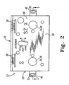
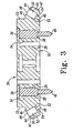
- FIGs. 2 and 3 show the cutting block 22 with the securing members 24 removed from a body portion 26 of the instrument 20.
- the body portion 26 is provided as a generally block-like structure including a first face 30, an opposite second face 32, and sidewalls 33 extending between the first face and the second face.
- the first face 30 may also be referred to herein as an upper face
- the second face 32 may be referred to as a lower face by virtue of the orientation of the cutting block 22 in the drawings.
- the cutting block may be oriented in numerous different directions including those orientations where the first face 30 is actually in a lower position than the second face 32.
- At least one cutting guide 28 extends through the body portion 26 of the cutting block 22 from the first face 30 to the second face 32.
- Each cutting guide 28 is generally provided as a rectangular slot that extends through the body portion 26 at a predetermined angle with respect to the face 30.
- Each slot is designed and dimensioned to receive a surgeon's cutting blade.
- the cutting block 22 includes a plurality of features designed to assist the surgeon and his or her team in stabilizing the block 22 on the bone during the cutting procedure.
- the cutting block 22 includes pins 34 positioned in holes 29 in the cutting block 28 that extend from the first face 30 to the second face 32.
- Each pin 34 includes a head 36, a shaft portion 38 and a tip portion 40.
- the head 36 is initially provided apart from the first surface, but the head 36 is tapped by the surgeon toward the first face 30 in order to drive the tip portion 40 of the pin 34 outward from the second face 32 and into the bone.
- Ears 42 are formed on opposing sidewalls of the cutting block 22.
- Each ear includes an upper surface 44 that extends from a shoulder 46 adjacent to the sidewall 33.
- the upper surface 44 is angled relative to the first face 30.
- An orifice 48 is formed in the upper surface 44 and the orifice 48 provides entry to a through hole 50 which extends down to the second surface 32 of the cutting block 22.
- Another orifice 49 to the through hole 50 is provided at the lower surface 32 of the cutting block.
- the through hole 50 is generally cylindrical and is defined by a centre axis provided at an angle relative to the upper and lower faces 30, 32 of the cutting block.
- the cross-sectional shape of the through hole 50 is circular in the disclosed embodiment, however it will be recognized that in other embodiments the through hole 50 may have other cross-sectional shapes, as discussed in further detail below.
- the through hole 50 includes a first portion 52 of a larger diameter and a second portion 54 of a smaller diameter.
- a shoulder 53 is formed in the through hole 50 at the intersection of the first portion 52 and the second portion 54.
- the diameter of the first portion 52 is sufficiently large to receive the end portion or shank of a handle or other securing member for the cutting block.
- the first diameter portion 52 is also large enough to receive the head of a bone screw, bone pin, or other axial bone fixation device.
- the diameter of the second portion 54 will only pass the shaft of the bone fixation device, and neither a handle shank nor the head of the bone fixation device will pass through the second diameter portion. Accordingly, the head of a bone fixation device will remain in the first portion 52 while the shaft of the bone fixation device extends through the second portion 54, past the second face 32, and into the bone when the cutting block 22 is positioned against a bone.
- FIG. 4 shows a securing arrangement 60 for a cutting block 22, which includes a handle 62 and a bone fixation device 64.
- the handle 62 includes a central portion 66 designed to be held in the hand of a surgical team member.
- the central portion is generally frusto-conical shaped with a disc portion 68 formed at the end of the handle 62.
- the disc portion provides a shoulder which allows a user to abut his or her finger against the disc portion when grasping the handle 62.
- the handle 62 further includes a shank 70 on the opposite end of the handle from the disc portion 68.
- the shank is designed to fit into the first portion 52 of the through hole 50 in the cutting block 22.
- the shank 70 is provided as an end knob that is shaped complementary to the shape of the first portion 52 of the through hole 50. For example, if the first portion 52 of the through hole is cylindrical in shape with a circular cross-section, the end knob 70 is also cylindrical in shape with a circular cross-section.
- the end knob 70 is designed and dimensioned such that the complete end knob 70 fits into the first portion of the through hole 50.
- a bone fixation device 64 in the form of a bone pin is shown in alignment with the handle 62.
- the bone pin 64 includes a head 74 and a shaft 76 with a sharp tip 78 on the end of the pin opposite the head 74.
- the bone pin is shown with a smooth surface on the shaft, but it will be recognized that the shaft could be provided with other surfaces, such as a threaded shaft.
- the bone pin 72 is designed and dimensioned for insertion in the through hole 50 of the cutting block 22.
- the head 74 of the pin 64 When inserted in the through hole 50, the head 74 of the pin 64 is retained in the first portion 52 of the through hole 50 and abuts the shoulder 53 in the through hole 50.
- the shaft 76 of the pin extends through the lower face 32 of the cutting block 22. Accordingly, the tip 78 and shaft 76 of the pin 64 may be inserted into the bone when the cutting block is used in a surgical procedure to assist in securing the cutting block to the bone.
- the surgeon may also choose to use the handle 62 for additional stabilization of the cutting block.
- the surgeon places the knob 70 in the first portion 52 of the through hole 50 of the cutting block 22 such that the knob 70 abuts the head 74 of the pin 64 in the through hole. Accordingly, with the arrangement of FIGs. 3 and 4 , a single hole in the cutting block may be used in association with two securing members 24, including a bone fixation device 64 and also a handle 62.
- FIGs. 5 to 10 show other examples of arrangements for securing instruments to the bone.
- an alternative handle 62 and bone fixation device 64 are shown.
- the bone securing device 64 is a bone screw 80 including a hex-shaped head 82, a threaded shaft 84, and a tip 86.
- the handle 62 is a slotted handle 90 including a hex-shaped end portion 91 and a slotted central portion 92.
- the hex-shaped end portion 91 is configured to work in association with a wrench such that the handle 62 may be turned by the wrench.
- Elongated slots 94 are provided on the central portion 92 to assist the user in grasping the handle 90.
- the shank 96 On the opposite end of the handle 90 from the hex-shaped end portion 91 is a circular shank 96.
- the shank 96 is designed with a circular outer circumference dimensioned to fit into the first portion 52 of the through hole 50 in the cutting block 22.
- the shank 96 is designed to interface with the head of the bone screw 80.
- the end portion 96 of the handle 90 includes a hex-shaped cavity 98 that is complimentary to the hex-shaped head 82 on the bone screw 80.
- the hex shaped head 82 of the bone screw 80 is configured to fit within the complementary hex-shaped cavity 98 of the handle 90, providing a coaxial and cannulated arrangement between the handle 62 and the bone screw 80.
- the bone screw 80 With the head 82 of the bone screw 80 positioned in the cavity 98 of the handle 90, the bone screw 80 is releasably secured to the handle 90.
- rotation of the handle 90 about its axis allows the handle 90 to be used as a wrench to turn the bone screw.
- the handle 90 is pulled away from the bone screw 80 in an axial direction, the handle 90 is released from engagement with the bone screw 80.
- both the handle 90 and the bone screw 80 may be inserted in the through hole 50. Insertion of the two parts many be accomplished with the bone screw 64 either separated from or in engagement with the handle 90.
- the handle 90 and bone screw 64 are inserted into the through hole 50, the shank 96 of the handle 90 and the head 82 of the bone screw are retained in the first portion 52 of the through hole 50.
- the threaded shaft 84 of the bone screw 64 extends through the second portion of the through hole and past the lower face 32 of the cutting block.
- the cannulated relationship between the head 82 of the bone screw 64 and the cavity 98 of the handle 90, along with their complimentary hexagonal shapes, provide a lock between these parts.
- rotation of the handle 90 also results in rotation of the bone screw 64, and the handle 90 may be used to drive the bone screw 64 into the bone.
- the handle 90 may be used to drive the bone screw 64 into the bone.
- both the bone screw 80 and handle 90 are shown inserted into the through hole 50 of the cutting block 22 in FIG. 7 , it will be appreciated that the surgeon may also choose to utilize only one of the two parts during a given surgical procedure.
- the bone screw 80 alone may be inserted into the through hole 50 of the cutting block 22 without the handle 90 in order to secure the cutting block 22 to the bone.
- the handle 90 may be used without the bone screw 80 to secure the cutting block 22 to the bone.
- the shank 96 of the handle 90 does not include a cavity 98.
- the shank 96 may be provided as a solid knob 99 designed to abut the head 82 of the bone screw 64.
- the handle 90 and bone screw 80 are not coupled, but instead abut against one another in the first portion 52 of the cutting block's through hole 50.
- the bone fixation device 64 is provided as a bone pin where the shaft is not threaded, such as that shown in FIG. 4
- the handle may be used to drive the bone pin into the bone.
- a surgeon may tap on the end 91 of the handle 90 with a mallet in order to drive the bone pin 80 into the bone until the head of the bone pin engages the shoulder 53 of the through hole 50.
- FIG. 9 shows yet another securing arrangement 60 for use with the bone cutting block 22 which is not part of the present invention, wherein the handle 62 is permanently attached to the bone fixation device 64, with the handle 62 and bone fixation device 64 formed as a single integral component.
- the bone fixation device is shown in FIG. 9 as being an unthreaded bone pin, it will be recognized that the bone fixation device could also be a threaded bone screw or other bone fixation device.
- the shank 96 of the handle 62 includes a locking feature designed to secure the handle to the cutting block.
- the locking feature is provided as threads 100 on the shank 96 of the handle 62.
- the threads 100 on the handle are designed to engage complimentary threads 101 provided in the first portion 52 of the through hole 50 of the cutting block 22. Engagement of the threads 100 and 101 provides an interlock between the handle 62 and the cutting block 22.
- the handle 62 is secured to the cutting block 22 and can not be pulled away from the cutting block in the axial direction without rotating the handle to disengage the threads 100, 101.
- the knob 70 of the handle 62 may include locking balls 105 embedded in retaining cavities in the handle 62. These locking balls 105 are designed to engage a complimentary annular recess (not shown) in the first portion 52 of the through hole 50 when the knob 70 of the handle is fully inserted into the first portion 52 of the through hole 50. When the locking balls 105 engage the annular recess of the through hole 50, the handle 62 is locked in the through hole 50 in the axial direction.
- a button 107 provided on the opposite end of the handle from the knob 70 provides a release feature for the locking balls.
- the button 107 is provided in association with a release mechanism inside the handle such that depression of the button 107 allows the balls to be depressed further into the retaining cavities in the handle 62.
- the handle may be inserted into or removed from the through hole.
- the button is released, it returns to its outward position and the balls also are forced outward in the retaining cavities of the knob 70.
- FIG. 11 Another arrangement where a locking feature is provided between the handle 62 and the cutting block 22 is shown in FIG. 11 .
- the locking feature is provided by the circumferential shape of the shank 96, such as hexagonal circumference 102 shown in FIG. 11 .
- This circumference 102 is designed to engage a complimentary cross-sectional shape provided in the first portion 52 of the through hole 50 in the cutting block 22.
- the handle 62 is locked in the through hole and prevented from rotating.
- the handle 62 may be easily removed from the through hole by pulling the handle 62 from the through hole in the axial direction, as no axial locking feature is provided with the embodiment of FIG. 11 .
- a hexagonal circumference has been shown in FIG. 11 , it will be recognized that numerous other shapes or arrangements are possible to provide locking features between the handle 62 and the cutting block 22.
Landscapes
- Health & Medical Sciences (AREA)
- Surgery (AREA)
- Life Sciences & Earth Sciences (AREA)
- Orthopedic Medicine & Surgery (AREA)
- General Health & Medical Sciences (AREA)
- Molecular Biology (AREA)
- Nuclear Medicine, Radiotherapy & Molecular Imaging (AREA)
- Veterinary Medicine (AREA)
- Public Health (AREA)
- Engineering & Computer Science (AREA)
- Biomedical Technology (AREA)
- Heart & Thoracic Surgery (AREA)
- Medical Informatics (AREA)
- Animal Behavior & Ethology (AREA)
- Oral & Maxillofacial Surgery (AREA)
- Dentistry (AREA)
- Physical Education & Sports Medicine (AREA)
- Transplantation (AREA)
- Neurology (AREA)
- Surgical Instruments (AREA)
- Orthopedics, Nursing, And Contraception (AREA)
Abstract
Description
- This invention relates to the field of orthopaedic surgery, and more particularly to instruments to be secured to a bone during orthopaedic surgery.
- Many orthopaedic procedures involve tools or other instruments that need to be secured to the bone. One exemplary instrument is the cutting block which is used during orthopaedic surgery to assist the surgeon in making bone cuts. Cutting blocks typically include slots or other guides that show the surgeon where the bone is to be cut. To ensure a proper cut, the cutting block must first be stabilized relative to the bone. With the cutting block stabilized, the cutting guides remain properly positioned and may be utilized by the surgeon.
- Various methods are available for stabilizing bone cutting instruments relative to a bone. For example, some surgeons prefer pin fixation to secure the cutting instrument. Other surgeons prefer handle fixation to secure the cutting instrument relative to the bone.
- With pin fixation, a smooth or threaded fixation pin is inserted through a hole and into the bone. The pin typically includes a head that presses against the instrument and holds the instrument in place when the pin is inserted into the bone. With handle fixation, the cutting instrument includes one or more holes configured to receive handles. Once the handles are inserted into the holes, they extend from the instrument. The operating room team holds the handles firmly to stabilize the cutting instrument relative to the bone for the surgeon.
- Surgical procedures, including orthopaedic surgical procedures, are becoming increasingly less invasive. Smaller surgical instruments are desired for use in association with these less invasive surgical procedures. Accordingly, it would be advantageous to provide a cutting instrument for use in orthopaedic procedures where the stabilization features offered on the instrument consume only a minimum amount of space on the instrument. It would be of further advantage if the stabilization features on the cutting instrument continued to offer surgeons various options for stabilizing the cutting instrument relative to the bone.
-
US-5910143 discloses an intramedullary alignment guide which is used to locate a cutting block relative to a patient's femur. The guide has a hole extending through its body portion and a handle member with a shank. The end of the handle member can be received in the hole in the body portion. Pins extend through the base of the handle unit. The holes in the base of the handle unit for the pins are offset relative to the hole in the base of the handle unit in which the handle member is received. - The invention provides an instrument set for use in a bone cutting step of an orthopaedic surgical procedure, as defined in claim 1.
- In at least one embodiment, the first portion of the at least one hole and a shank of the handle include locking features designed to provide an interlock between the hole and the handle. For example, the locking features may comprise a particular shape defined by the first portion of the hole and a complimentary shape defined by the shank of the handle. In another embodiment, the locking features comprise threads in the first portion of the hole and complimentary threads on the shank of the handle.
- Embodiments of the invention are described below by way of example with reference to the accompanying drawings, in which:
-
FIG. 1 shows a bone cutting instrument placed on the end of an exposed bone; -
FIG. 2 shows the bone cutting instrument ofFIG. 1 with the handles removed from the cutting block; -
FIG. 3 shows a cross-sectional view of the bone cutting instrument ofFIG. 2 along line III-III; -
FIG. 4 shows one embodiment of a handle and bone fixation member for use with the cutting instrument ofFIG. 2 ; -
FIG. 5 shows an alternative embodiment of a handle and bone fixation member; -
FIG. 6 shows a cross-sectional view of the handle ofFIG. 5 along line VI-VI; -
FIG. 7 shows the handle and bone fixation member ofFIG. 5 positioned in a cutting instrument; -
FIG. 8 shows an alternative cross-sectional view of the handle ofFIG. 5 along line VI-VI; -
FIG. 9 shows yet another alternative embodiment of a handle and bone fixation member; -
FIG. 10 shows the handle and bone fixation member ofFIG. 9 positioned in a cutting instrument; and -
FIG. 11 shows an alternative cross-sectional view of the handle ofFIG. 5 along line VI-VI. - Referring to the drawings,
FIG. 1 shows abone cutting instrument 20 placed on the end of an exposedfemur 12, which is to be cut using theinstrument 20. The bone cutting instrument includes acutting block 22 and securingmembers 24 used to secure the cutting block against thebone 12. -
FIGs. 2 and3 show thecutting block 22 with the securingmembers 24 removed from abody portion 26 of theinstrument 20. Thebody portion 26 is provided as a generally block-like structure including afirst face 30, an oppositesecond face 32, andsidewalls 33 extending between the first face and the second face. Thefirst face 30 may also be referred to herein as an upper face, and thesecond face 32 may be referred to as a lower face by virtue of the orientation of thecutting block 22 in the drawings. However, it will be recognized that the cutting block may be oriented in numerous different directions including those orientations where thefirst face 30 is actually in a lower position than thesecond face 32. - At least one
cutting guide 28 extends through thebody portion 26 of thecutting block 22 from thefirst face 30 to thesecond face 32. Eachcutting guide 28 is generally provided as a rectangular slot that extends through thebody portion 26 at a predetermined angle with respect to theface 30. Each slot is designed and dimensioned to receive a surgeon's cutting blade. When thesecond face 32 of thecutting block 22 is properly positioned on a bone surface, eachcutting guide 28 provides a pilot to assist the surgeon in making proper cuts in the bone for a particular surgical procedure. In particular, when the surgeon's cutting blade is inserted into the cutting guide, the blade is properly oriented with respect to the bone such that an appropriate cut is made for the surgical procedure. - In addition to the
cutting guides 28, thecutting block 22 includes a plurality of features designed to assist the surgeon and his or her team in stabilizing theblock 22 on the bone during the cutting procedure. For example, thecutting block 22 includespins 34 positioned inholes 29 in thecutting block 28 that extend from thefirst face 30 to thesecond face 32. Eachpin 34 includes ahead 36, ashaft portion 38 and a tip portion 40. Thehead 36 is initially provided apart from the first surface, but thehead 36 is tapped by the surgeon toward thefirst face 30 in order to drive the tip portion 40 of thepin 34 outward from thesecond face 32 and into the bone. -
Ears 42 are formed on opposing sidewalls of thecutting block 22. Each ear includes anupper surface 44 that extends from ashoulder 46 adjacent to thesidewall 33. Theupper surface 44 is angled relative to thefirst face 30. Anorifice 48 is formed in theupper surface 44 and theorifice 48 provides entry to a throughhole 50 which extends down to thesecond surface 32 of thecutting block 22. Anotherorifice 49 to thethrough hole 50 is provided at thelower surface 32 of the cutting block. The throughhole 50 is generally cylindrical and is defined by a centre axis provided at an angle relative to the upper andlower faces through hole 50 is circular in the disclosed embodiment, however it will be recognized that in other embodiments the throughhole 50 may have other cross-sectional shapes, as discussed in further detail below. - The
through hole 50 includes afirst portion 52 of a larger diameter and asecond portion 54 of a smaller diameter. Ashoulder 53 is formed in the throughhole 50 at the intersection of thefirst portion 52 and thesecond portion 54. As explained in further detail below, the diameter of thefirst portion 52 is sufficiently large to receive the end portion or shank of a handle or other securing member for the cutting block. Thefirst diameter portion 52 is also large enough to receive the head of a bone screw, bone pin, or other axial bone fixation device. However, the diameter of thesecond portion 54 will only pass the shaft of the bone fixation device, and neither a handle shank nor the head of the bone fixation device will pass through the second diameter portion. Accordingly, the head of a bone fixation device will remain in thefirst portion 52 while the shaft of the bone fixation device extends through thesecond portion 54, past thesecond face 32, and into the bone when the cuttingblock 22 is positioned against a bone. -
FIG. 4 shows a securingarrangement 60 for a cuttingblock 22, which includes ahandle 62 and abone fixation device 64. Thehandle 62 includes acentral portion 66 designed to be held in the hand of a surgical team member. The central portion is generally frusto-conical shaped with adisc portion 68 formed at the end of thehandle 62. The disc portion provides a shoulder which allows a user to abut his or her finger against the disc portion when grasping thehandle 62. - The
handle 62 further includes ashank 70 on the opposite end of the handle from thedisc portion 68. The shank is designed to fit into thefirst portion 52 of the throughhole 50 in the cuttingblock 22. Theshank 70 is provided as an end knob that is shaped complementary to the shape of thefirst portion 52 of the throughhole 50. For example, if thefirst portion 52 of the through hole is cylindrical in shape with a circular cross-section, theend knob 70 is also cylindrical in shape with a circular cross-section. Theend knob 70 is designed and dimensioned such that thecomplete end knob 70 fits into the first portion of the throughhole 50. - In the example of
FIG. 4 , abone fixation device 64 in the form of a bone pin is shown in alignment with thehandle 62. Thebone pin 64 includes a head 74 and ashaft 76 with asharp tip 78 on the end of the pin opposite the head 74. The bone pin is shown with a smooth surface on the shaft, but it will be recognized that the shaft could be provided with other surfaces, such as a threaded shaft. In any event, the bone pin 72 is designed and dimensioned for insertion in the throughhole 50 of the cuttingblock 22. - When inserted in the through
hole 50, the head 74 of thepin 64 is retained in thefirst portion 52 of the throughhole 50 and abuts theshoulder 53 in the throughhole 50. Theshaft 76 of the pin extends through thelower face 32 of the cuttingblock 22. Accordingly, thetip 78 andshaft 76 of thepin 64 may be inserted into the bone when the cutting block is used in a surgical procedure to assist in securing the cutting block to the bone. - With the
bone pin 64 in place, the surgeon may also choose to use thehandle 62 for additional stabilization of the cutting block. To use the handle, the surgeon places theknob 70 in thefirst portion 52 of the throughhole 50 of the cuttingblock 22 such that theknob 70 abuts the head 74 of thepin 64 in the through hole. Accordingly, with the arrangement ofFIGs. 3 and4 , a single hole in the cutting block may be used in association with two securingmembers 24, including abone fixation device 64 and also ahandle 62. -
FIGs. 5 to 10 show other examples of arrangements for securing instruments to the bone. In the example ofFIG. 5 , analternative handle 62 andbone fixation device 64 are shown. In this example, thebone securing device 64 is abone screw 80 including a hex-shapedhead 82, a threadedshaft 84, and atip 86. Thehandle 62 is a slottedhandle 90 including a hex-shapedend portion 91 and a slottedcentral portion 92. The hex-shapedend portion 91 is configured to work in association with a wrench such that thehandle 62 may be turned by the wrench.Elongated slots 94 are provided on thecentral portion 92 to assist the user in grasping thehandle 90. - On the opposite end of the
handle 90 from the hex-shapedend portion 91 is acircular shank 96. Theshank 96 is designed with a circular outer circumference dimensioned to fit into thefirst portion 52 of the throughhole 50 in the cuttingblock 22. In addition, theshank 96 is designed to interface with the head of thebone screw 80. In particular, as shown inFIG. 6 , theend portion 96 of thehandle 90 includes a hex-shapedcavity 98 that is complimentary to the hex-shapedhead 82 on thebone screw 80. The hex shapedhead 82 of thebone screw 80 is configured to fit within the complementary hex-shapedcavity 98 of thehandle 90, providing a coaxial and cannulated arrangement between thehandle 62 and thebone screw 80. With thehead 82 of thebone screw 80 positioned in thecavity 98 of thehandle 90, thebone screw 80 is releasably secured to thehandle 90. In particular, rotation of thehandle 90 about its axis allows thehandle 90 to be used as a wrench to turn the bone screw. However, the when thehandle 90 is pulled away from thebone screw 80 in an axial direction, thehandle 90 is released from engagement with thebone screw 80. - As shown in
FIG. 7 , both thehandle 90 and thebone screw 80 may be inserted in the throughhole 50. Insertion of the two parts many be accomplished with thebone screw 64 either separated from or in engagement with thehandle 90. When thehandle 90 andbone screw 64 are inserted into the throughhole 50, theshank 96 of thehandle 90 and thehead 82 of the bone screw are retained in thefirst portion 52 of the throughhole 50. The threadedshaft 84 of thebone screw 64 extends through the second portion of the through hole and past thelower face 32 of the cutting block. As mentioned previously, the cannulated relationship between thehead 82 of thebone screw 64 and thecavity 98 of thehandle 90, along with their complimentary hexagonal shapes, provide a lock between these parts. Accordingly, rotation of thehandle 90 also results in rotation of thebone screw 64, and thehandle 90 may be used to drive thebone screw 64 into the bone. It will be recognized that although a hexagonal shape is shown inFIGs. 5 and 6 as providing the locking engagement between thebone screw 64 and thehandle 90, other shapes or locking arrangements may be provided between thehandle 90 and thebone screw 80. - Although both the
bone screw 80 and handle 90 are shown inserted into the throughhole 50 of the cuttingblock 22 inFIG. 7 , it will be appreciated that the surgeon may also choose to utilize only one of the two parts during a given surgical procedure. Thus, thebone screw 80 alone may be inserted into the throughhole 50 of the cuttingblock 22 without thehandle 90 in order to secure the cuttingblock 22 to the bone. Alternatively, thehandle 90 may be used without thebone screw 80 to secure the cuttingblock 22 to the bone. - In an alternative to that shown in
FIGs. 5 to 7 (which is not part of the present invention), theshank 96 of thehandle 90 does not include acavity 98. Instead, as shown inFIG. 8 , theshank 96 may be provided as asolid knob 99 designed to abut thehead 82 of thebone screw 64. In this embodiment, thehandle 90 andbone screw 80 are not coupled, but instead abut against one another in thefirst portion 52 of the cutting block's throughhole 50. If thebone fixation device 64 is provided as a bone pin where the shaft is not threaded, such as that shown inFIG. 4 , the handle may be used to drive the bone pin into the bone. A surgeon may tap on theend 91 of thehandle 90 with a mallet in order to drive thebone pin 80 into the bone until the head of the bone pin engages theshoulder 53 of the throughhole 50. -
FIG. 9 shows yet another securingarrangement 60 for use with thebone cutting block 22 which is not part of the present invention, wherein thehandle 62 is permanently attached to thebone fixation device 64, with thehandle 62 andbone fixation device 64 formed as a single integral component. Although the bone fixation device is shown inFIG. 9 as being an unthreaded bone pin, it will be recognized that the bone fixation device could also be a threaded bone screw or other bone fixation device. - As shown in
FIG. 9 , theshank 96 of thehandle 62 includes a locking feature designed to secure the handle to the cutting block. In this embodiment, the locking feature is provided asthreads 100 on theshank 96 of thehandle 62. Thethreads 100 on the handle are designed to engagecomplimentary threads 101 provided in thefirst portion 52 of the throughhole 50 of the cuttingblock 22. Engagement of thethreads handle 62 and the cuttingblock 22. Thus, when thethreads 100 of thehandle 62 engage thethreads 101 of the cuttingblock 22, thehandle 62 is secured to the cuttingblock 22 and can not be pulled away from the cutting block in the axial direction without rotating the handle to disengage thethreads - Other locking arrangements for the
handle 62 and the cuttingblock 64 might be used instead of that shown inFIG. 10 . For example, returning again toFIG. 4 , theknob 70 of thehandle 62 may include lockingballs 105 embedded in retaining cavities in thehandle 62. These lockingballs 105 are designed to engage a complimentary annular recess (not shown) in thefirst portion 52 of the throughhole 50 when theknob 70 of the handle is fully inserted into thefirst portion 52 of the throughhole 50. When the lockingballs 105 engage the annular recess of the throughhole 50, thehandle 62 is locked in the throughhole 50 in the axial direction. Abutton 107 provided on the opposite end of the handle from theknob 70 provides a release feature for the locking balls. In particular, thebutton 107 is provided in association with a release mechanism inside the handle such that depression of thebutton 107 allows the balls to be depressed further into the retaining cavities in thehandle 62. When the lockingballs 105 are depressed further into the retaining cavities, the handle may be inserted into or removed from the through hole. When the button is released, it returns to its outward position and the balls also are forced outward in the retaining cavities of theknob 70. - Another arrangement where a locking feature is provided between the
handle 62 and the cuttingblock 22 is shown inFIG. 11 . In this embodiment, the locking feature is provided by the circumferential shape of theshank 96, such as hexagonal circumference 102 shown inFIG. 11 . This circumference 102 is designed to engage a complimentary cross-sectional shape provided in thefirst portion 52 of the throughhole 50 in the cuttingblock 22. When thehexagonal shank 96 of thehandle 62 is inserted into the hexagonalfirst portion 52 of the throughhole 50, thehandle 62 is locked in the through hole and prevented from rotating. However, in this locking arrangement, thehandle 62 may be easily removed from the through hole by pulling thehandle 62 from the through hole in the axial direction, as no axial locking feature is provided with the embodiment ofFIG. 11 . Although a hexagonal circumference has been shown inFIG. 11 , it will be recognized that numerous other shapes or arrangements are possible to provide locking features between thehandle 62 and the cuttingblock 22.
Claims (4)
- An instrument set for use in a bone cutting step of an orthopaedic surgical procedure, comprising:a cutting block (22) including a body portion (26) which provides a cutting guide (28), and has at least one hole (50) extending through the body portion, the at least one hole including a first opening (52) in the body portion which communicates with an opposing opening (54) in the body portion,a handle member (62) having a shank (70) at one end whose shape is complementary to the shape of the first opening in the body portion so that the shank fits into the said hole through the first opening, anda bone engaging member (64) having a shaft (76) which can extend through the opposing opening in the body portion of the cutting block,characterised in that the bone engaging member (64) is in the form of a bone pin or a bone screw and has a head (74), and the handle member (62) has an end portion with a cavity (98) formed therein whose shape is complimentary to that of the head of the bone engaging member so that the head of the bone engaging member can be received in the cavity in the handle in a cannulated relationship to releasibly connect the bone engaging member to the handle.
- The bone cutting instrument of claim 1 in which the shank (96) of the handle member (62) has an external thread (100) and the first opening (52) has a complementary internal thread (101) so that the handle member can be locked in the hole (50) in the body portion (26) of the cutting block (22).
- The bone cutting instrument of claim 1 in which the opposing opening (54) in the body portion (26) of the cutting block (22) is smaller than the first opening (52).
- The bone cutting instrument of claim 1 in which the head (74) of the bone engaging member (64) can fit in the first opening (52) in the body portion (26) of the cutting block (22) but is sized so that it will not pass through the opposing opening (54).
Applications Claiming Priority (2)
| Application Number | Priority Date | Filing Date | Title |
|---|---|---|---|
| US11/895,840 US9629639B2 (en) | 2007-08-28 | 2007-08-28 | Arrangement for securing instrument to bone |
| EP08162562A EP2030581B1 (en) | 2007-08-28 | 2008-08-18 | Arrangement for securing an instrument to a bone |
Related Parent Applications (2)
| Application Number | Title | Priority Date | Filing Date |
|---|---|---|---|
| EP08162562.6 Division | 2008-08-18 | ||
| EP08162562A Division EP2030581B1 (en) | 2007-08-28 | 2008-08-18 | Arrangement for securing an instrument to a bone |
Publications (2)
| Publication Number | Publication Date |
|---|---|
| EP2298191A1 EP2298191A1 (en) | 2011-03-23 |
| EP2298191B1 true EP2298191B1 (en) | 2014-01-22 |
Family
ID=39791413
Family Applications (2)
| Application Number | Title | Priority Date | Filing Date |
|---|---|---|---|
| EP08162562A Active EP2030581B1 (en) | 2007-08-28 | 2008-08-18 | Arrangement for securing an instrument to a bone |
| EP10178799.2A Active EP2298191B1 (en) | 2007-08-28 | 2008-08-18 | Arrangement for securing an instrument to a bone |
Family Applications Before (1)
| Application Number | Title | Priority Date | Filing Date |
|---|---|---|---|
| EP08162562A Active EP2030581B1 (en) | 2007-08-28 | 2008-08-18 | Arrangement for securing an instrument to a bone |
Country Status (4)
| Country | Link |
|---|---|
| US (1) | US9629639B2 (en) |
| EP (2) | EP2030581B1 (en) |
| AT (1) | ATE489042T1 (en) |
| DE (1) | DE602008003630D1 (en) |
Families Citing this family (4)
| Publication number | Priority date | Publication date | Assignee | Title |
|---|---|---|---|---|
| US8435241B2 (en) * | 2007-12-20 | 2013-05-07 | Depuy Products, Inc. | Keel punch impactor with connection device |
| US8574302B2 (en) * | 2010-12-20 | 2013-11-05 | Warsaw Orthopedic, Inc. | Bone augmentation device |
| CA2836651C (en) | 2012-12-27 | 2016-03-22 | Wright Medical Technology, Inc. | Ankle replacement system and method |
| CA2904652C (en) | 2013-03-14 | 2021-11-02 | Wright Medical Technology, Inc. | Ankle replacement system and method |
Family Cites Families (13)
| Publication number | Priority date | Publication date | Assignee | Title |
|---|---|---|---|---|
| US5275603A (en) | 1992-02-20 | 1994-01-04 | Wright Medical Technology, Inc. | Rotationally and angularly adjustable tibial cutting guide and method of use |
| US5445642A (en) * | 1992-09-01 | 1995-08-29 | Depuy Inc. | Method for installing a femoral component |
| US5484446A (en) | 1994-06-27 | 1996-01-16 | Zimmer, Inc. | Alignment guide for use in orthopaedic surgery |
| US5910143A (en) * | 1994-12-16 | 1999-06-08 | Exactech, Inc. | Intramedullary alignment guide tool |
| US5709689A (en) * | 1995-09-25 | 1998-01-20 | Wright Medical Technology, Inc. | Distal femur multiple resection guide |
| WO1997030648A1 (en) * | 1996-02-23 | 1997-08-28 | Midwest Orthopedic Research Foundation | Device and method for distal femur cutting and prothesis measuring |
| ATE309752T1 (en) * | 1997-02-11 | 2005-12-15 | Michelson Gary K | SYSTEM FOR ANTERIOR PLATING OF THE CERVICAL SPINE |
| US6096043A (en) * | 1998-12-18 | 2000-08-01 | Depuy Orthopaedics, Inc. | Epicondylar axis alignment-femoral positioning drill guide |
| US6758850B2 (en) * | 2002-03-29 | 2004-07-06 | Depuy Orthopaedics, Inc. | Instruments and methods for flexion gap adjustment |
| US7104997B2 (en) * | 2003-06-19 | 2006-09-12 | Lionberger Jr David R | Cutting guide apparatus and surgical method for use in knee arthroplasty |
| US7744635B2 (en) * | 2004-06-09 | 2010-06-29 | Spinal Generations, Llc | Spinal fixation system |
| WO2006081378A2 (en) * | 2005-01-27 | 2006-08-03 | Depuy Spine Inc. | System for facilitating attachment of a delivery instrument with a bone screw |
| JP4944103B2 (en) | 2005-05-20 | 2012-05-30 | スミス アンド ネフュー インコーポレーテッド | Patellar femoral implant and device |
-
2007
- 2007-08-28 US US11/895,840 patent/US9629639B2/en not_active Expired - Fee Related
-
2008
- 2008-08-18 EP EP08162562A patent/EP2030581B1/en active Active
- 2008-08-18 EP EP10178799.2A patent/EP2298191B1/en active Active
- 2008-08-18 AT AT08162562T patent/ATE489042T1/en not_active IP Right Cessation
- 2008-08-18 DE DE602008003630T patent/DE602008003630D1/en active Active
Also Published As
| Publication number | Publication date |
|---|---|
| US20090062801A1 (en) | 2009-03-05 |
| EP2030581B1 (en) | 2010-11-24 |
| DE602008003630D1 (en) | 2011-01-05 |
| ATE489042T1 (en) | 2010-12-15 |
| EP2030581A1 (en) | 2009-03-04 |
| US9629639B2 (en) | 2017-04-25 |
| EP2298191A1 (en) | 2011-03-23 |
Similar Documents
| Publication | Publication Date | Title |
|---|---|---|
| EP1605809B1 (en) | Surgical retractor system | |
| US7837689B2 (en) | Plate holder assembly having bone plate seating confirmation arrangement | |
| US20090088767A1 (en) | Guide assembly for use in a medical procedure | |
| EP1343423B1 (en) | Surgical system comprising handle and cannula | |
| US5810828A (en) | Adjustable depth drill guide | |
| EP1878394B1 (en) | Orthopaedic fixation plate having threaded guides | |
| EP1567070B1 (en) | Adjustable length tap and method for drilling and tapping a bore in bone | |
| US7887548B2 (en) | Screw insertion guide tube with window | |
| EP0686375B1 (en) | Surgical instrument for use during connection of a fractured bone | |
| US20090254094A1 (en) | Ratcheting mechanical driver for cannulated surgical systems | |
| EP1955667B1 (en) | Global nail screw retaining screwdriver | |
| WO1998035621A9 (en) | Adjustable depth drill guide | |
| CA2574142C (en) | Medical system, body implant, adaptor device and method for spatially adjusting an aiming device relative to the body implant | |
| EP2030581B1 (en) | Arrangement for securing an instrument to a bone | |
| EP3624737B1 (en) | Implant assembly tools | |
| US20220008109A1 (en) | Surgical tool for positioning a surgical device, surgical device and kit | |
| EP4142629B1 (en) | Self-retaining screw and screwdriver | |
| US20250241662A1 (en) | Guidewire-capturing surgical instrument | |
| EP1808138B1 (en) | Medical system and system parts for spatially adjusting an aiming device relative to a body implant |
Legal Events
| Date | Code | Title | Description |
|---|---|---|---|
| PUAI | Public reference made under article 153(3) epc to a published international application that has entered the european phase |
Free format text: ORIGINAL CODE: 0009012 |
|
| AC | Divisional application: reference to earlier application |
Ref document number: 2030581 Country of ref document: EP Kind code of ref document: P |
|
| AK | Designated contracting states |
Kind code of ref document: A1 Designated state(s): AT BE BG CH CY CZ DE DK EE ES FI FR GB GR HR HU IE IS IT LI LT LU LV MC MT NL NO PL PT RO SE SI SK TR |
|
| 17P | Request for examination filed |
Effective date: 20110809 |
|
| GRAP | Despatch of communication of intention to grant a patent |
Free format text: ORIGINAL CODE: EPIDOSNIGR1 |
|
| RIC1 | Information provided on ipc code assigned before grant |
Ipc: A61B 17/86 20060101ALI20130828BHEP Ipc: A61B 17/88 20060101ALI20130828BHEP Ipc: A61B 17/15 20060101AFI20130828BHEP Ipc: A61B 17/17 20060101ALI20130828BHEP |
|
| INTG | Intention to grant announced |
Effective date: 20130919 |
|
| GRAS | Grant fee paid |
Free format text: ORIGINAL CODE: EPIDOSNIGR3 |
|
| GRAA | (expected) grant |
Free format text: ORIGINAL CODE: 0009210 |
|
| AC | Divisional application: reference to earlier application |
Ref document number: 2030581 Country of ref document: EP Kind code of ref document: P |
|
| AK | Designated contracting states |
Kind code of ref document: B1 Designated state(s): AT BE BG CH CY CZ DE DK EE ES FI FR GB GR HR HU IE IS IT LI LT LU LV MC MT NL NO PL PT RO SE SI SK TR |
|
| REG | Reference to a national code |
Ref country code: GB Ref legal event code: FG4D |
|
| REG | Reference to a national code |
Ref country code: CH Ref legal event code: EP Ref country code: CH Ref legal event code: NV Representative=s name: E. BLUM AND CO. AG PATENT- UND MARKENANWAELTE , CH |
|
| REG | Reference to a national code |
Ref country code: AT Ref legal event code: REF Ref document number: 650378 Country of ref document: AT Kind code of ref document: T Effective date: 20140215 |
|
| REG | Reference to a national code |
Ref country code: IE Ref legal event code: FG4D |
|
| REG | Reference to a national code |
Ref country code: DE Ref legal event code: R096 Ref document number: 602008030155 Country of ref document: DE Effective date: 20140306 |
|
| REG | Reference to a national code |
Ref country code: NL Ref legal event code: VDEP Effective date: 20140122 |
|
| REG | Reference to a national code |
Ref country code: AT Ref legal event code: MK05 Ref document number: 650378 Country of ref document: AT Kind code of ref document: T Effective date: 20140122 |
|
| REG | Reference to a national code |
Ref country code: LT Ref legal event code: MG4D |
|
| PG25 | Lapsed in a contracting state [announced via postgrant information from national office to epo] |
Ref country code: NO Free format text: LAPSE BECAUSE OF FAILURE TO SUBMIT A TRANSLATION OF THE DESCRIPTION OR TO PAY THE FEE WITHIN THE PRESCRIBED TIME-LIMIT Effective date: 20140422 Ref country code: IS Free format text: LAPSE BECAUSE OF FAILURE TO SUBMIT A TRANSLATION OF THE DESCRIPTION OR TO PAY THE FEE WITHIN THE PRESCRIBED TIME-LIMIT Effective date: 20140522 Ref country code: LT Free format text: LAPSE BECAUSE OF FAILURE TO SUBMIT A TRANSLATION OF THE DESCRIPTION OR TO PAY THE FEE WITHIN THE PRESCRIBED TIME-LIMIT Effective date: 20140122 |
|
| PG25 | Lapsed in a contracting state [announced via postgrant information from national office to epo] |
Ref country code: NL Free format text: LAPSE BECAUSE OF FAILURE TO SUBMIT A TRANSLATION OF THE DESCRIPTION OR TO PAY THE FEE WITHIN THE PRESCRIBED TIME-LIMIT Effective date: 20140122 Ref country code: PT Free format text: LAPSE BECAUSE OF FAILURE TO SUBMIT A TRANSLATION OF THE DESCRIPTION OR TO PAY THE FEE WITHIN THE PRESCRIBED TIME-LIMIT Effective date: 20140522 Ref country code: FI Free format text: LAPSE BECAUSE OF FAILURE TO SUBMIT A TRANSLATION OF THE DESCRIPTION OR TO PAY THE FEE WITHIN THE PRESCRIBED TIME-LIMIT Effective date: 20140122 Ref country code: AT Free format text: LAPSE BECAUSE OF FAILURE TO SUBMIT A TRANSLATION OF THE DESCRIPTION OR TO PAY THE FEE WITHIN THE PRESCRIBED TIME-LIMIT Effective date: 20140122 Ref country code: ES Free format text: LAPSE BECAUSE OF FAILURE TO SUBMIT A TRANSLATION OF THE DESCRIPTION OR TO PAY THE FEE WITHIN THE PRESCRIBED TIME-LIMIT Effective date: 20140122 Ref country code: SE Free format text: LAPSE BECAUSE OF FAILURE TO SUBMIT A TRANSLATION OF THE DESCRIPTION OR TO PAY THE FEE WITHIN THE PRESCRIBED TIME-LIMIT Effective date: 20140122 Ref country code: CY Free format text: LAPSE BECAUSE OF FAILURE TO SUBMIT A TRANSLATION OF THE DESCRIPTION OR TO PAY THE FEE WITHIN THE PRESCRIBED TIME-LIMIT Effective date: 20140122 |
|
| PG25 | Lapsed in a contracting state [announced via postgrant information from national office to epo] |
Ref country code: LV Free format text: LAPSE BECAUSE OF FAILURE TO SUBMIT A TRANSLATION OF THE DESCRIPTION OR TO PAY THE FEE WITHIN THE PRESCRIBED TIME-LIMIT Effective date: 20140122 Ref country code: HR Free format text: LAPSE BECAUSE OF FAILURE TO SUBMIT A TRANSLATION OF THE DESCRIPTION OR TO PAY THE FEE WITHIN THE PRESCRIBED TIME-LIMIT Effective date: 20140122 Ref country code: BE Free format text: LAPSE BECAUSE OF FAILURE TO SUBMIT A TRANSLATION OF THE DESCRIPTION OR TO PAY THE FEE WITHIN THE PRESCRIBED TIME-LIMIT Effective date: 20140122 |
|
| REG | Reference to a national code |
Ref country code: DE Ref legal event code: R097 Ref document number: 602008030155 Country of ref document: DE |
|
| PG25 | Lapsed in a contracting state [announced via postgrant information from national office to epo] |
Ref country code: CZ Free format text: LAPSE BECAUSE OF FAILURE TO SUBMIT A TRANSLATION OF THE DESCRIPTION OR TO PAY THE FEE WITHIN THE PRESCRIBED TIME-LIMIT Effective date: 20140122 Ref country code: EE Free format text: LAPSE BECAUSE OF FAILURE TO SUBMIT A TRANSLATION OF THE DESCRIPTION OR TO PAY THE FEE WITHIN THE PRESCRIBED TIME-LIMIT Effective date: 20140122 Ref country code: DK Free format text: LAPSE BECAUSE OF FAILURE TO SUBMIT A TRANSLATION OF THE DESCRIPTION OR TO PAY THE FEE WITHIN THE PRESCRIBED TIME-LIMIT Effective date: 20140122 Ref country code: RO Free format text: LAPSE BECAUSE OF FAILURE TO SUBMIT A TRANSLATION OF THE DESCRIPTION OR TO PAY THE FEE WITHIN THE PRESCRIBED TIME-LIMIT Effective date: 20140122 |
|
| PG25 | Lapsed in a contracting state [announced via postgrant information from national office to epo] |
Ref country code: PL Free format text: LAPSE BECAUSE OF FAILURE TO SUBMIT A TRANSLATION OF THE DESCRIPTION OR TO PAY THE FEE WITHIN THE PRESCRIBED TIME-LIMIT Effective date: 20140122 Ref country code: SK Free format text: LAPSE BECAUSE OF FAILURE TO SUBMIT A TRANSLATION OF THE DESCRIPTION OR TO PAY THE FEE WITHIN THE PRESCRIBED TIME-LIMIT Effective date: 20140122 |
|
| PLBE | No opposition filed within time limit |
Free format text: ORIGINAL CODE: 0009261 |
|
| STAA | Information on the status of an ep patent application or granted ep patent |
Free format text: STATUS: NO OPPOSITION FILED WITHIN TIME LIMIT |
|
| 26N | No opposition filed |
Effective date: 20141023 |
|
| REG | Reference to a national code |
Ref country code: DE Ref legal event code: R097 Ref document number: 602008030155 Country of ref document: DE Effective date: 20141023 |
|
| PG25 | Lapsed in a contracting state [announced via postgrant information from national office to epo] |
Ref country code: LU Free format text: LAPSE BECAUSE OF FAILURE TO SUBMIT A TRANSLATION OF THE DESCRIPTION OR TO PAY THE FEE WITHIN THE PRESCRIBED TIME-LIMIT Effective date: 20140818 Ref country code: MC Free format text: LAPSE BECAUSE OF FAILURE TO SUBMIT A TRANSLATION OF THE DESCRIPTION OR TO PAY THE FEE WITHIN THE PRESCRIBED TIME-LIMIT Effective date: 20140122 |
|
| PG25 | Lapsed in a contracting state [announced via postgrant information from national office to epo] |
Ref country code: SI Free format text: LAPSE BECAUSE OF FAILURE TO SUBMIT A TRANSLATION OF THE DESCRIPTION OR TO PAY THE FEE WITHIN THE PRESCRIBED TIME-LIMIT Effective date: 20140122 |
|
| PG25 | Lapsed in a contracting state [announced via postgrant information from national office to epo] |
Ref country code: BG Free format text: LAPSE BECAUSE OF FAILURE TO SUBMIT A TRANSLATION OF THE DESCRIPTION OR TO PAY THE FEE WITHIN THE PRESCRIBED TIME-LIMIT Effective date: 20140122 |
|
| PG25 | Lapsed in a contracting state [announced via postgrant information from national office to epo] |
Ref country code: IT Free format text: LAPSE BECAUSE OF FAILURE TO SUBMIT A TRANSLATION OF THE DESCRIPTION OR TO PAY THE FEE WITHIN THE PRESCRIBED TIME-LIMIT Effective date: 20140122 Ref country code: MT Free format text: LAPSE BECAUSE OF FAILURE TO SUBMIT A TRANSLATION OF THE DESCRIPTION OR TO PAY THE FEE WITHIN THE PRESCRIBED TIME-LIMIT Effective date: 20140122 Ref country code: GR Free format text: LAPSE BECAUSE OF FAILURE TO SUBMIT A TRANSLATION OF THE DESCRIPTION OR TO PAY THE FEE WITHIN THE PRESCRIBED TIME-LIMIT Effective date: 20140423 |
|
| REG | Reference to a national code |
Ref country code: FR Ref legal event code: PLFP Year of fee payment: 9 |
|
| PG25 | Lapsed in a contracting state [announced via postgrant information from national office to epo] |
Ref country code: HU Free format text: LAPSE BECAUSE OF FAILURE TO SUBMIT A TRANSLATION OF THE DESCRIPTION OR TO PAY THE FEE WITHIN THE PRESCRIBED TIME-LIMIT; INVALID AB INITIO Effective date: 20080818 Ref country code: TR Free format text: LAPSE BECAUSE OF FAILURE TO SUBMIT A TRANSLATION OF THE DESCRIPTION OR TO PAY THE FEE WITHIN THE PRESCRIBED TIME-LIMIT Effective date: 20140122 |
|
| REG | Reference to a national code |
Ref country code: FR Ref legal event code: PLFP Year of fee payment: 10 |
|
| REG | Reference to a national code |
Ref country code: FR Ref legal event code: PLFP Year of fee payment: 11 |
|
| PGFP | Annual fee paid to national office [announced via postgrant information from national office to epo] |
Ref country code: GB Payment date: 20220630 Year of fee payment: 15 |
|
| PGFP | Annual fee paid to national office [announced via postgrant information from national office to epo] |
Ref country code: IE Payment date: 20220712 Year of fee payment: 15 Ref country code: DE Payment date: 20220608 Year of fee payment: 15 |
|
| PGFP | Annual fee paid to national office [announced via postgrant information from national office to epo] |
Ref country code: FR Payment date: 20220709 Year of fee payment: 15 |
|
| PGFP | Annual fee paid to national office [announced via postgrant information from national office to epo] |
Ref country code: CH Payment date: 20220802 Year of fee payment: 15 |
|
| REG | Reference to a national code |
Ref country code: DE Ref legal event code: R119 Ref document number: 602008030155 Country of ref document: DE |
|
| REG | Reference to a national code |
Ref country code: CH Ref legal event code: PL |
|
| GBPC | Gb: european patent ceased through non-payment of renewal fee |
Effective date: 20230818 |
|
| PG25 | Lapsed in a contracting state [announced via postgrant information from national office to epo] |
Ref country code: CH Free format text: LAPSE BECAUSE OF NON-PAYMENT OF DUE FEES Effective date: 20230831 |
|
| REG | Reference to a national code |
Ref country code: IE Ref legal event code: MM4A |
|
| PG25 | Lapsed in a contracting state [announced via postgrant information from national office to epo] |
Ref country code: IE Free format text: LAPSE BECAUSE OF NON-PAYMENT OF DUE FEES Effective date: 20230818 |
|
| PG25 | Lapsed in a contracting state [announced via postgrant information from national office to epo] |
Ref country code: GB Free format text: LAPSE BECAUSE OF NON-PAYMENT OF DUE FEES Effective date: 20230818 |
|
| PG25 | Lapsed in a contracting state [announced via postgrant information from national office to epo] |
Ref country code: IE Free format text: LAPSE BECAUSE OF NON-PAYMENT OF DUE FEES Effective date: 20230818 Ref country code: GB Free format text: LAPSE BECAUSE OF NON-PAYMENT OF DUE FEES Effective date: 20230818 Ref country code: FR Free format text: LAPSE BECAUSE OF NON-PAYMENT OF DUE FEES Effective date: 20230831 Ref country code: DE Free format text: LAPSE BECAUSE OF NON-PAYMENT OF DUE FEES Effective date: 20240301 |