EP2296984B1 - Motorized gluing group - Google Patents
Motorized gluing group Download PDFInfo
- Publication number
- EP2296984B1 EP2296984B1 EP08761337A EP08761337A EP2296984B1 EP 2296984 B1 EP2296984 B1 EP 2296984B1 EP 08761337 A EP08761337 A EP 08761337A EP 08761337 A EP08761337 A EP 08761337A EP 2296984 B1 EP2296984 B1 EP 2296984B1
- Authority
- EP
- European Patent Office
- Prior art keywords
- gluing
- group
- glue
- gluing group
- stator
- Prior art date
- Legal status (The legal status is an assumption and is not a legal conclusion. Google has not performed a legal analysis and makes no representation as to the accuracy of the status listed.)
- Not-in-force
Links
Images

Classifications
-
- B—PERFORMING OPERATIONS; TRANSPORTING
- B65—CONVEYING; PACKING; STORING; HANDLING THIN OR FILAMENTARY MATERIAL
- B65C—LABELLING OR TAGGING MACHINES, APPARATUS, OR PROCESSES
- B65C9/00—Details of labelling machines or apparatus
- B65C9/20—Gluing the labels or articles
- B65C9/22—Gluing the labels or articles by wetting, e.g. by applying liquid glue or a liquid to a dry glue coating
- B65C9/2247—Gluing the labels or articles by wetting, e.g. by applying liquid glue or a liquid to a dry glue coating using liquid rollers or bands
-
- B—PERFORMING OPERATIONS; TRANSPORTING
- B65—CONVEYING; PACKING; STORING; HANDLING THIN OR FILAMENTARY MATERIAL
- B65C—LABELLING OR TAGGING MACHINES, APPARATUS, OR PROCESSES
- B65C9/00—Details of labelling machines or apparatus
- B65C2009/0071—Details of glueing devices
- B65C2009/0075—Constructional details of glueing rollers
-
- B—PERFORMING OPERATIONS; TRANSPORTING
- B65—CONVEYING; PACKING; STORING; HANDLING THIN OR FILAMENTARY MATERIAL
- B65C—LABELLING OR TAGGING MACHINES, APPARATUS, OR PROCESSES
- B65C9/00—Details of labelling machines or apparatus
- B65C2009/0071—Details of glueing devices
- B65C2009/0078—Constructional details of doctor blades
-
- Y—GENERAL TAGGING OF NEW TECHNOLOGICAL DEVELOPMENTS; GENERAL TAGGING OF CROSS-SECTIONAL TECHNOLOGIES SPANNING OVER SEVERAL SECTIONS OF THE IPC; TECHNICAL SUBJECTS COVERED BY FORMER USPC CROSS-REFERENCE ART COLLECTIONS [XRACs] AND DIGESTS
- Y10—TECHNICAL SUBJECTS COVERED BY FORMER USPC
- Y10T—TECHNICAL SUBJECTS COVERED BY FORMER US CLASSIFICATION
- Y10T156/00—Adhesive bonding and miscellaneous chemical manufacture
- Y10T156/17—Surface bonding means and/or assemblymeans with work feeding or handling means
- Y10T156/1798—Surface bonding means and/or assemblymeans with work feeding or handling means with liquid adhesive or adhesive activator applying means
Definitions
- the present invention relates to a gluing group to be used mainly in labelling machines for labelling containers such as bottles, particularly for cold glue labelling groups.
- a gluing group of the kind is know from DE 197 41 476 A1 , according to the preamble of claim 1.
- Labelling machines for gluing labels and transferring them onto the surface of containers are known and widespread used.
- the containers are carried by a carrousel and come into contact with a labelling unit.
- the labelling unit comprises a so called "vacuum drum” that receives a label strip from a roll feeding group, cuts the label at the appropriate length, glues the label by means of appropriate means, such as a glue roll, spray and injector systems or the like, and finally transfers the label to the container.
- the labels are pre-cut and are dispensed from a stack.
- the present invention addresses specifically those machines that use a glue roll for gluing labels or other items.
- the glue roll is normally driven by the main carrousel motor, through a mechanical transmission (gear system, belts or the like).
- a dedicated brushless motor is used, but again this is operatively connected to the glue roll by drive gears or belts.
- a motorised glue roll is indicated with the numeral 1.
- the motorised glue roll 1 comprises motor means 2, having a stator 4 and a rotor 5, and gluing means 3 mounted on said rotor 5.
- the gluing means 3 are directly mounted on the rotor 5, i.e., they are mounted to the rotor 5 without interposition of transmission means like gears, belts, shafts or the like.
- the said motor means 2 preferably are a direct drive (DC) torque motor, more preferably a brushless motor. These motor means 2 have a stator 4, comprising the wound element, positioned coaxially around the rotor 5.
- DC direct drive
- the stator 4 has a cylindrical shape and is open at the bottom, while its top is closed and terminates with a turret element 6 hosting power and signal connectors 7, 7' for the motor.
- An outwardly faced flange 8 is positioned in the region between the top portion of the stator 4 and the turret element 6.
- the flange 8 comprises one or more holes 9, for examples threaded holes, for fixing the glue roll 1 to the gluing group 10.
- stator 4 turret element 6 and flange 8 are integral.
- the rotor 5 is of substantially cylindrical shape and comprises linking means 11 that connect the rotor 5 to the gluing means 3.
- the linking means 11 are a flanged element that extends outwardly from the rotor 5, bridges the stator 4 at its bottom end and links the gluing means 3.
- rotor 5, linking means 11 and gluing means 3 are integral.
- the gluing means 3 comprises a tubular element with a cylindrical outer surface and an inner surface that is substantially complementary in shape to the outer surface of the stator 4, but has a greater diameter, so that a gap 12 is created between the two surfaces.
- the gap 12 serves the function to allow the circulation of a cooling fluid, such as cooling air. This is important, as the glue, which is deposited onto the outer surface of the gluing means 3, should not be heated above 30-40°C. Since the motor generates heat, the gap 12 with circulating cooling fluid allows the gluing means 3 to be kept at an appropriate temperature.
- the fluid circulation in the gap 12 can be achieved by suction of external air due to the vortex created by rotation of the gluing means 3 with respect to the stator 4.
- suitable fan means can also be provided in order to inflate air or other cooling fluid from the bottom of the glue roll 1.
- the linking means 11 may comprise openings 13 to put into flow communication the gap 12 with the exterior.
- the glue roll 1 is mounted on a gluing group 10 which comprises a frame 14 and glue spreading means 15 for spreading glue onto the outer surface of the glue roll 1.
- the frame 14 comprises an upper plate 16 that can be fixed to a labelling machine (not shown) through a fixing element 17.
- the upper plate 16 is provided with a through hole of suitable diameter to couple with the turret element 6 of the glue roll 1 and suitable through holes designed to engage with fixing means 18, such as screws or the like, to fix the glue roll 1 to the upper plate 16 of the frame 14.
- fixing means 18 such as screws or the like
- delivery means for the glue.
- These delivery means are conventional ones and can be simply constituted by an external cannula that takes the glue from a remote tank and delivers it directly onto the top portion of the outer surface of the gluing means 3.
- the frame 14 also comprises a base element 19 onto which the glue roll 1 is mounted.
- the base element 19 comprises collecting means 20 for the excess glue that drains from the gluing means 3, the said excess glue being removed and possibly recycled through a collecting duct 21.
- the frame 14 supports the said glue spreading means 15. These latter comprise an elongated member 22 that extends between the upper plate 16 and the base element 19 of the frame 14, all along the outer surface of the gluing means 3.
- the elongated member 22 is hinged at the top and at the bottom to the upper plate 16 and the base element 19, respectively, by means of suitable hinging pins (only the upper hinging pin 23 between the elongated member 22 and the top is visible).
- the elongated member 22 carries a spreading blade 24, that is removably mounted on it and can be fixed by suitable fixing means 25 that can be operated through suitable knobs.
- a handle 26 allows the spreading blade 24 to be taken away from the gluing means 3 surface, by rotating the elongated member 22 around the hinging pins 23, for maintainance operations.
- Adjustment means 27 such as a micrometric screw means, are also provided to finely tune the distance of the spreading blade 24 from the gluing means 3 surface, when the spreading blade 24 is in the operating position. In such a way, it is possible to obtain an uniform layer of glue of the wanted thickness on the gluing means 3.
- These adjustment means 27 act onto the spreading blade 24 by means of suitable leverages or wedges according to conventional means.
- On-off means are also provided for contacting the spreading blade 24 with the outer surface of the gluing means 3 or alternatively for setting it at a distance from the said surface normally corresponding to the operating position.
- These on-off means for example an electronic valve controlled by a PLC, make the elongated member 22 to rotate of a small angle in order to set the blade 24 at the contact position with the gluing means 3 or at the operating position.
- the blade 24 is made to contact the surface of the gluing means 3 while rotating the glue roll 1 in order to clean such a surface from residual dried glue that can deposit and dry during the maintainance operations of the machine. This cleaning operation is normally performed before reactivating the labeling machine after a rest period.
- the on-off means can be operated by the PLC according to a predefined pulse cleaning cycle, wherein the blade 24 is made to contact the gluing means 3 for a few seconds (2-3 seconds) and then is taken away for again a few seconds and so on.
- This cleaning cycle allows the motor not to be overloaded.
- gluing group 10 of the invention does not substantially differ from the conventional machines and has been already clarified in the above description of the preferred embodiments.
- the provision of the aerated gap 12 solves the problem of heating of the surface of the gluing means 3, which would otherwise be detrimental to the gluing operations.
Landscapes
- Coating Apparatus (AREA)
- Labeling Devices (AREA)
Description
- The present invention relates to a gluing group to be used mainly in labelling machines for labelling containers such as bottles, particularly for cold glue labelling groups. A gluing group of the kind is know from
DE 197 41 476 A1 , according to the preamble ofclaim 1. - Labelling machines for gluing labels and transferring them onto the surface of containers are known and widespread used. In these machines the containers are carried by a carrousel and come into contact with a labelling unit. In one type of machines, the labelling unit comprises a so called "vacuum drum" that receives a label strip from a roll feeding group, cuts the label at the appropriate length, glues the label by means of appropriate means, such as a glue roll, spray and injector systems or the like, and finally transfers the label to the container. In another type, the labels are pre-cut and are dispensed from a stack.
- The present invention addresses specifically those machines that use a glue roll for gluing labels or other items.
- In conventional machines, the glue roll is normally driven by the main carrousel motor, through a mechanical transmission (gear system, belts or the like). In some cases, a dedicated brushless motor is used, but again this is operatively connected to the glue roll by drive gears or belts. These systems have a first disadvantage due to their bulky dimensions and the difficulties in mounting or dismounting the group from the machine. Besides this problem, another important disadvantage consists in the bad coupling tolerances between glue roll and label handling device that is again dependent from the mechanical transmission of the movement.
- This latter problem is even more sensible in the labelling machines that use pre-cut labels, like the ones typically used for labelling beer bottles. These machines comprise a rotating carrousel, wherein a plurality of arcuated pads are rotatably mounted. The movement of the arcuated pads, which are usually coated with a gummy layer, is such as that, when each pad comes into contact with the glue roll for taking glue, it rotates in the opposite direction in order to contact its whole surface with the glue roll. The overall movement of the arcuated pads combines the circular movement of the carrousel on which they are mounted with their own eccentric rotation, so that it is eccentric. Thus, a bad movement coupling between glue roll and pads results in these latter being dragged. The gummy surface is therefore subjected to a continuous friction bringing to the necessity to replace the pads frequently.
- It is therefore an object of the present invention to provide a gluing group that overcomes the above drawbacks, as defined in the appended claims.
- Further features and advantages of the present invention will be better understood from the description of a preferred embodiment, which is given below by way of a non-limiting illustration, with reference to the following figures:
-
Fig. 1 is a perspective cross section view of a glue roll; -
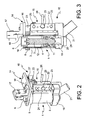
Fig. 2 is a perspective view of a gluing group carrying the glue roll offigure 1 ; -
Fig. 3 is a side sectional view of the gluing group offigure 2 . - With reference to the figures, a motorised glue roll is indicated with the
numeral 1. Themotorised glue roll 1 comprises motor means 2, having astator 4 and arotor 5, and gluing means 3 mounted on saidrotor 5. Preferably, the gluing means 3 are directly mounted on therotor 5, i.e., they are mounted to therotor 5 without interposition of transmission means like gears, belts, shafts or the like. - The said motor means 2 preferably are a direct drive (DC) torque motor, more preferably a brushless motor. These motor means 2 have a
stator 4, comprising the wound element, positioned coaxially around therotor 5. - In the motor means 2, the
stator 4 has a cylindrical shape and is open at the bottom, while its top is closed and terminates with aturret element 6 hosting power andsignal connectors 7, 7' for the motor. An outwardly facedflange 8 is positioned in the region between the top portion of thestator 4 and theturret element 6. Theflange 8 comprises one ormore holes 9, for examples threaded holes, for fixing theglue roll 1 to thegluing group 10. - Preferably,
stator 4,turret element 6 andflange 8 are integral. - The
rotor 5 is of substantially cylindrical shape and comprises linking means 11 that connect therotor 5 to the gluing means 3. Preferably, the linking means 11 are a flanged element that extends outwardly from therotor 5, bridges thestator 4 at its bottom end and links the gluing means 3. Preferably,rotor 5, linking means 11 and gluing means 3 are integral. - The gluing means 3 comprises a tubular element with a cylindrical outer surface and an inner surface that is substantially complementary in shape to the outer surface of the
stator 4, but has a greater diameter, so that agap 12 is created between the two surfaces. Thegap 12 serves the function to allow the circulation of a cooling fluid, such as cooling air. This is important, as the glue, which is deposited onto the outer surface of the gluing means 3, should not be heated above 30-40°C. Since the motor generates heat, thegap 12 with circulating cooling fluid allows the gluing means 3 to be kept at an appropriate temperature. - The fluid circulation in the
gap 12 can be achieved by suction of external air due to the vortex created by rotation of the gluing means 3 with respect to thestator 4. However, suitable fan means can also be provided in order to inflate air or other cooling fluid from the bottom of theglue roll 1. - To this end, the linking means 11 may comprise
openings 13 to put into flow communication thegap 12 with the exterior. - The
glue roll 1 is mounted on agluing group 10 which comprises aframe 14 and glue spreading means 15 for spreading glue onto the outer surface of theglue roll 1. - The
frame 14 comprises anupper plate 16 that can be fixed to a labelling machine (not shown) through afixing element 17. Theupper plate 16 is provided with a through hole of suitable diameter to couple with theturret element 6 of theglue roll 1 and suitable through holes designed to engage withfixing means 18, such as screws or the like, to fix theglue roll 1 to theupper plate 16 of theframe 14. In particular, theturret element 6 of theglue roll 1 is inserted into the corresponding hole of theupper plate 16 from the bottom upwards, while the fixing means 18 are inserted from the top, pass through the through holes in theupper plate 16 and engage theholes 9 of theflange 8 of theglue roll 1. - On the
upper plate 16 can also be mounted delivery means for the glue. These delivery means (not shown) are conventional ones and can be simply constituted by an external cannula that takes the glue from a remote tank and delivers it directly onto the top portion of the outer surface of the gluing means 3. - The
frame 14 also comprises abase element 19 onto which theglue roll 1 is mounted. Thebase element 19 comprises collecting means 20 for the excess glue that drains from the gluing means 3, the said excess glue being removed and possibly recycled through acollecting duct 21. - The
frame 14 supports the said glue spreading means 15. These latter comprise anelongated member 22 that extends between theupper plate 16 and thebase element 19 of theframe 14, all along the outer surface of the gluing means 3. Theelongated member 22 is hinged at the top and at the bottom to theupper plate 16 and thebase element 19, respectively, by means of suitable hinging pins (only the upper hingingpin 23 between theelongated member 22 and the top is visible). - The
elongated member 22 carries a spreadingblade 24, that is removably mounted on it and can be fixed bysuitable fixing means 25 that can be operated through suitable knobs. - A
handle 26 allows the spreadingblade 24 to be taken away from the gluing means 3 surface, by rotating theelongated member 22 around the hingingpins 23, for maintainance operations. - Adjustment means 27, such as a micrometric screw means, are also provided to finely tune the distance of the spreading
blade 24 from the gluing means 3 surface, when the spreadingblade 24 is in the operating position. In such a way, it is possible to obtain an uniform layer of glue of the wanted thickness on the gluing means 3. These adjustment means 27 act onto the spreadingblade 24 by means of suitable leverages or wedges according to conventional means. - On-off means (not shown) are also provided for contacting the spreading
blade 24 with the outer surface of the gluing means 3 or alternatively for setting it at a distance from the said surface normally corresponding to the operating position. These on-off means, for example an electronic valve controlled by a PLC, make theelongated member 22 to rotate of a small angle in order to set theblade 24 at the contact position with the gluing means 3 or at the operating position. Theblade 24 is made to contact the surface of the gluing means 3 while rotating theglue roll 1 in order to clean such a surface from residual dried glue that can deposit and dry during the maintainance operations of the machine. This cleaning operation is normally performed before reactivating the labeling machine after a rest period. - According to a particular embodiment, the on-off means can be operated by the PLC according to a predefined pulse cleaning cycle, wherein the
blade 24 is made to contact thegluing means 3 for a few seconds (2-3 seconds) and then is taken away for again a few seconds and so on. This cleaning cycle allows the motor not to be overloaded. - The functioning of the
gluing group 10 of the invention does not substantially differ from the conventional machines and has been already clarified in the above description of the preferred embodiments. - The advantages of the inventive apparatus are clear. No transmission means are provided between the motor means and the
glue roll 1, as the motor directly transmits the motion to the roll. In such a way, the effects of bad tolerances are dramatically reduced. - The provision of the
aerated gap 12 solves the problem of heating of the surface of the gluing means 3, which would otherwise be detrimental to the gluing operations. - Also the cleaning operations of the
glue roll 1 have been optimized thanks to the PLC controlled on-off means for the spreadingblade 24, which provides for an efficient cleaning cycle. - It will be appreciated that only particular embodiments of the present invention have been described herein, to which those skilled in the art will be able to make any and all modifications necessary for its adjustment to specific applications, without however departing from the scope of protection of the present invention as defined in the annexed claims.
Claims (19)
- Gluing group (10) comprising a glue roll (1) and a frame (14) for mounting the said gluing group (10) to a labelling machine, characterised in that the said glue roll (1) comprises motor means (2), having a stator (4) and a rotor (5), and gluing means (3) mounted on said rotor (5).
- Gluing group (10) according to claim 1, wherein the said gluing means (3) are directly mounted on the said rotor (5).
- Gluing group (10) according to claim 1 or 2, wherein the said stator (4) is positioned coaxially around the said rotor (5) and the said gluing means (3) are positioned coaxially around the said stator (4), linking means (11) connecting the said rotor (5) to the said gluing means (3).
- Gluing group (10) according to claim 3, wherein the said rotor (5), linking means (11) and gluing means (3) are integral.
- Gluing group (10) according to any of claims 3 to 4, wherein between the inner surface of the said gluing means (3) and the outer surface of the said stator (4) is created a gap (12) for circulating a cooling fluid such as air.
- Gluing group (10) according to claim 5, wherein the cooling fluid is force-circulated through fan means.
- Gluing group (10) according to any of claims from 1 to 6, wherein the top end of the said stator (4) terminates with a turret element (6) hosting power and signal connectors (7, 7') for the motor, an outwardly faced flange (8) being positioned in the region between the top portion of the stator (4) and the turret element (6), the flange (8) comprising one or more holes (9) for fixing the glue roll (1) to the gluing group (10).
- Gluing group (10) according to claim 7, wherein stator (4), turret element (6) and flange (8) are integral.
- Gluing group (10) according to claim 7 , wherein the said frame (14) comprises an upper plate (16) provided with a through hole of suitable diameter to couple with the turret element (6) of the glue roll (1) and suitable through holes designed to engage with fixing means (18) to fix the glue roll (1) to the upper plate (16) of the frame (14).
- Gluing group (10) according to any of claims from 1 to 9, wherein the said frame (14) comprises a base element (19) onto which the glue roll (1) is mounted, the said base element (19) comprising collecting means (20) for the excess glue that drains from the gluing means (3) and a collecting duct (21) for removing and recycling the said excess glue.
- Gluing group (10) according to any of claims 1 to 10, further comprising glue spreading means (15) for spreading a layer of glue onto the outer surface of the gluing means (3) of said glue roll (1).
- Gluing group (10) according to claims 9, 10 and 11, wherein the said glue spreading means (15) comprise an elongated member (22) that extends between the upper plate (16) and the base element (19) of the frame (14) and that is hinged at the top and at the bottom to the upper plate (16) and the base element (19), respectively.
- Gluing group (10) according to claim 12, wherein the said elongated member (22) carries a spreading blade (24), which is removably mounted on it.
- Gluing group (10) according to claim 13, wherein the said elongated member (22) comprises a handle (26) allowing the spreading blade (24) to be taken away from the surface of the gluing means (3), by rotating the elongated member (22) around its hinging axis, for maintainance operations.
- Gluing group (10) according to claim 13 or 14, wherein adjustment means (27) are provided to finely tune the distance of the spreading blade (24) from the surface of the gluing means (3), when the spreading blade (24) is in the operating position.
- Gluing group (10) according to any of claims from 13 to 15, wherein on-off means are provided for contacting the spreading blade (24) with the outer surface of the gluing means (3) or alternatively for setting it at a distance from the said surface normally corresponding to the operating position.
- Gluing group (10) according to claim 16, wherein the said on-off means are an electronic valve controlled by a PLC, which makes the elongated member (22) to rotate of a small angle in order to set the spreading blade (24) at the contact position with the gluing means (3) or at the operating position.
- Gluing group (10) according to claim 17, wherein the said on-off means can be operated by the PLC according to a predefined pulse cleaning cycle, wherein the spreading blade (24) is made to contact the gluing means (3) for a few seconds and then is taken away for again a few seconds and so on.
- Gluing group (10) according to any of claims from 1 to 18, wherein the said motor means (2) are a direct drive torque motor, preferably a brushless motor.
Applications Claiming Priority (1)
| Application Number | Priority Date | Filing Date | Title |
|---|---|---|---|
| PCT/EP2008/058026 WO2009155970A1 (en) | 2008-06-24 | 2008-06-24 | Motorized glue roll |
Publications (2)
| Publication Number | Publication Date |
|---|---|
| EP2296984A1 EP2296984A1 (en) | 2011-03-23 |
| EP2296984B1 true EP2296984B1 (en) | 2012-09-05 |
Family
ID=40364358
Family Applications (1)
| Application Number | Title | Priority Date | Filing Date |
|---|---|---|---|
| EP08761337A Not-in-force EP2296984B1 (en) | 2008-06-24 | 2008-06-24 | Motorized gluing group |
Country Status (6)
| Country | Link |
|---|---|
| US (1) | US20110162804A1 (en) |
| EP (1) | EP2296984B1 (en) |
| JP (1) | JP2011525459A (en) |
| CN (1) | CN102099254B (en) |
| ES (1) | ES2394125T3 (en) |
| WO (1) | WO2009155970A1 (en) |
Cited By (1)
| Publication number | Priority date | Publication date | Assignee | Title |
|---|---|---|---|---|
| DE102013109999B3 (en) * | 2013-09-11 | 2015-01-22 | Khs Gmbh | Device and cleaning unit for cleaning a glue roller of a labeling unit for applying labels to containers or bottles |
Families Citing this family (7)
| Publication number | Priority date | Publication date | Assignee | Title |
|---|---|---|---|---|
| DE102011002590A1 (en) * | 2011-01-12 | 2012-07-12 | Krones Aktiengesellschaft | Gluing unit with removable glue tank and attachable cleaning unit |
| DE102012219554A1 (en) * | 2012-10-25 | 2014-04-30 | Krones Ag | gluing unit |
| DE102012219552A1 (en) * | 2012-10-25 | 2014-04-30 | Krones Ag | Glue roller for a labeling device |
| CN106269613B (en) * | 2015-06-29 | 2018-07-06 | 永春县永荣信息科技有限公司 | A kind of butanone paint removal rifle |
| CN107457149A (en) * | 2017-09-01 | 2017-12-12 | 江门市秦粤照明科技有限公司 | One kind automation lamp holder adhesive supplier |
| DE102019106642A1 (en) * | 2019-03-15 | 2020-09-17 | Homag Gmbh | Device for removing hot melt adhesive |
| CN118665812B (en) * | 2024-04-18 | 2026-03-24 | 江苏新美星包装机械股份有限公司 | The roller assembly mechanism in a hot melt adhesive labeling machine |
Family Cites Families (12)
| Publication number | Priority date | Publication date | Assignee | Title |
|---|---|---|---|---|
| FR1192050A (en) * | 1958-02-28 | 1959-10-23 | Brondel | Improvement in labeling machines |
| DE2632332C3 (en) * | 1976-07-17 | 1983-03-10 | Kronseder, Hermann, 8404 Wörth | Labeling device for bottles |
| DE3300008C2 (en) * | 1982-05-05 | 1984-10-04 | Jagenberg AG, 4000 Düsseldorf | Glue roller for a labeling station |
| SU1465357A1 (en) * | 1987-07-10 | 1989-03-15 | Черкасское Производственное Объединение "Продмаш" | Glue applicator roller of labelling machine |
| DE4006837C1 (en) * | 1990-03-05 | 1991-04-18 | Krones Ag Hermann Kronseder Maschinenfabrik, 8402 Neutraubling, De | Bottle label applicator machine - has vacuum cylinder to move label past glue applicator roller |
| DE19741476C5 (en) * | 1997-09-15 | 2010-06-02 | Krones Ag | Machine for treating vessels |
| DE19938878B4 (en) * | 1999-08-17 | 2022-10-06 | Khs Gmbh | One-part or multi-part glue scraper that can be swiveled onto a glue roller in a labeling machine for containers, in particular bottles |
| JP2003029483A (en) * | 2001-07-18 | 2003-01-29 | Ricoh Co Ltd | Image forming device |
| CN2583115Y (en) * | 2002-09-20 | 2003-10-29 | 郑州华萦化纤科技有限责任公司 | Self-driven friction roll |
| DE102004058542A1 (en) * | 2004-12-03 | 2006-06-08 | Nordson Corporation, Westlake | Rotary applicator head and label applicator for applying labels |
| DE102004061669A1 (en) * | 2004-12-22 | 2006-07-13 | Man Roland Druckmaschinen Ag | Printing machine roller and printing press cylinder |
| DE102006051360A1 (en) * | 2006-10-27 | 2008-05-21 | Khs Ag | gluing |
-
2008
- 2008-06-24 CN CN2008801298805A patent/CN102099254B/en not_active Expired - Fee Related
- 2008-06-24 ES ES08761337T patent/ES2394125T3/en active Active
- 2008-06-24 US US12/999,264 patent/US20110162804A1/en not_active Abandoned
- 2008-06-24 WO PCT/EP2008/058026 patent/WO2009155970A1/en not_active Ceased
- 2008-06-24 JP JP2011515123A patent/JP2011525459A/en not_active Ceased
- 2008-06-24 EP EP08761337A patent/EP2296984B1/en not_active Not-in-force
Cited By (1)
| Publication number | Priority date | Publication date | Assignee | Title |
|---|---|---|---|---|
| DE102013109999B3 (en) * | 2013-09-11 | 2015-01-22 | Khs Gmbh | Device and cleaning unit for cleaning a glue roller of a labeling unit for applying labels to containers or bottles |
Also Published As
| Publication number | Publication date |
|---|---|
| WO2009155970A1 (en) | 2009-12-30 |
| ES2394125T3 (en) | 2013-01-22 |
| EP2296984A1 (en) | 2011-03-23 |
| US20110162804A1 (en) | 2011-07-07 |
| CN102099254A (en) | 2011-06-15 |
| CN102099254B (en) | 2013-02-13 |
| JP2011525459A (en) | 2011-09-22 |
Similar Documents
| Publication | Publication Date | Title |
|---|---|---|
| US20110162804A1 (en) | Motorized glue roll | |
| CN100558602C (en) | A rotary labeling machine | |
| US6971219B2 (en) | Beverage bottling plant for filling bottles with a liquid beverage filling material and a labelling station for labelling filled bottles and other containers | |
| CN211766898U (en) | Double-deck cardboard label composite drying device | |
| CN103612803A (en) | Rotary hot melting adhesive pre-cutting labeling machine | |
| CN108177837B (en) | Label sticking device without backing paper | |
| CN119078358A (en) | An automated equipment for processing self-adhesive label paper | |
| CN213133855U (en) | Automatic press-fitting machine | |
| CN221339586U (en) | Self-adhesive laminating machine | |
| WO1995011833A1 (en) | Apparatus and method for labelling containers using thermal bonding | |
| CN223408339U (en) | Labeling device for PP bottle | |
| KR100942162B1 (en) | Apparatus for pressing finish material bonding furniture edge | |
| CN219898837U (en) | Dispensing drying treatment equipment for controller structure | |
| CN224212382U (en) | Labeller with sticky tape winding seals | |
| CN224114400U (en) | Automatic glue dripping device | |
| EP2345136A1 (en) | Motorized roll for labelling machines and labelling machine comprising such a roll | |
| CN112156943B (en) | A spot welding machine with an anti-spill structure for dispensing liquid used in the production of high-frequency transformers | |
| CN215098805U (en) | Labeling device for canned food tank body | |
| CN220680413U (en) | Stainless steel kitchen utensils and appliances production burnishing device | |
| CN223234185U (en) | Gluing device applied to printing package | |
| CN220836331U (en) | Gluing device | |
| CN223764928U (en) | Full-automatic labeling and conveying device | |
| CN223918685U (en) | Laminating device for label processing | |
| CN215100891U (en) | A kind of sheet thermal coating device for document bag production | |
| CN217043266U (en) | Glue spraying nozzle of cold glue automatic glue spraying device |
Legal Events
| Date | Code | Title | Description |
|---|---|---|---|
| PUAI | Public reference made under article 153(3) epc to a published international application that has entered the european phase |
Free format text: ORIGINAL CODE: 0009012 |
|
| 17P | Request for examination filed |
Effective date: 20101221 |
|
| AK | Designated contracting states |
Kind code of ref document: A1 Designated state(s): AT BE BG CH CY CZ DE DK EE ES FI FR GB GR HR HU IE IS IT LI LT LU LV MC MT NL NO PL PT RO SE SI SK TR |
|
| AX | Request for extension of the european patent |
Extension state: AL BA MK RS |
|
| DAX | Request for extension of the european patent (deleted) | ||
| RTI1 | Title (correction) |
Free format text: MOTORIZED GLUING GROUP |
|
| GRAP | Despatch of communication of intention to grant a patent |
Free format text: ORIGINAL CODE: EPIDOSNIGR1 |
|
| GRAS | Grant fee paid |
Free format text: ORIGINAL CODE: EPIDOSNIGR3 |
|
| GRAA | (expected) grant |
Free format text: ORIGINAL CODE: 0009210 |
|
| AK | Designated contracting states |
Kind code of ref document: B1 Designated state(s): AT BE BG CH CY CZ DE DK EE ES FI FR GB GR HR HU IE IS IT LI LT LU LV MC MT NL NO PL PT RO SE SI SK TR |
|
| REG | Reference to a national code |
Ref country code: GB Ref legal event code: FG4D |
|
| REG | Reference to a national code |
Ref country code: CH Ref legal event code: EP |
|
| REG | Reference to a national code |
Ref country code: AT Ref legal event code: REF Ref document number: 573997 Country of ref document: AT Kind code of ref document: T Effective date: 20120915 |
|
| REG | Reference to a national code |
Ref country code: IE Ref legal event code: FG4D |
|
| REG | Reference to a national code |
Ref country code: DE Ref legal event code: R096 Ref document number: 602008018572 Country of ref document: DE Effective date: 20121031 |
|
| REG | Reference to a national code |
Ref country code: AT Ref legal event code: MK05 Ref document number: 573997 Country of ref document: AT Kind code of ref document: T Effective date: 20120905 |
|
| REG | Reference to a national code |
Ref country code: ES Ref legal event code: FG2A Ref document number: 2394125 Country of ref document: ES Kind code of ref document: T3 Effective date: 20130122 |
|
| REG | Reference to a national code |
Ref country code: NL Ref legal event code: VDEP Effective date: 20120905 |
|
| PG25 | Lapsed in a contracting state [announced via postgrant information from national office to epo] |
Ref country code: AT Free format text: LAPSE BECAUSE OF FAILURE TO SUBMIT A TRANSLATION OF THE DESCRIPTION OR TO PAY THE FEE WITHIN THE PRESCRIBED TIME-LIMIT Effective date: 20120905 Ref country code: FI Free format text: LAPSE BECAUSE OF FAILURE TO SUBMIT A TRANSLATION OF THE DESCRIPTION OR TO PAY THE FEE WITHIN THE PRESCRIBED TIME-LIMIT Effective date: 20120905 Ref country code: HR Free format text: LAPSE BECAUSE OF FAILURE TO SUBMIT A TRANSLATION OF THE DESCRIPTION OR TO PAY THE FEE WITHIN THE PRESCRIBED TIME-LIMIT Effective date: 20120905 Ref country code: NO Free format text: LAPSE BECAUSE OF FAILURE TO SUBMIT A TRANSLATION OF THE DESCRIPTION OR TO PAY THE FEE WITHIN THE PRESCRIBED TIME-LIMIT Effective date: 20121205 Ref country code: LT Free format text: LAPSE BECAUSE OF FAILURE TO SUBMIT A TRANSLATION OF THE DESCRIPTION OR TO PAY THE FEE WITHIN THE PRESCRIBED TIME-LIMIT Effective date: 20120905 |
|
| REG | Reference to a national code |
Ref country code: LT Ref legal event code: MG4D Effective date: 20120905 |
|
| PG25 | Lapsed in a contracting state [announced via postgrant information from national office to epo] |
Ref country code: SI Free format text: LAPSE BECAUSE OF FAILURE TO SUBMIT A TRANSLATION OF THE DESCRIPTION OR TO PAY THE FEE WITHIN THE PRESCRIBED TIME-LIMIT Effective date: 20120905 Ref country code: GR Free format text: LAPSE BECAUSE OF FAILURE TO SUBMIT A TRANSLATION OF THE DESCRIPTION OR TO PAY THE FEE WITHIN THE PRESCRIBED TIME-LIMIT Effective date: 20121206 Ref country code: LV Free format text: LAPSE BECAUSE OF FAILURE TO SUBMIT A TRANSLATION OF THE DESCRIPTION OR TO PAY THE FEE WITHIN THE PRESCRIBED TIME-LIMIT Effective date: 20120905 Ref country code: SE Free format text: LAPSE BECAUSE OF FAILURE TO SUBMIT A TRANSLATION OF THE DESCRIPTION OR TO PAY THE FEE WITHIN THE PRESCRIBED TIME-LIMIT Effective date: 20120905 |
|
| PG25 | Lapsed in a contracting state [announced via postgrant information from national office to epo] |
Ref country code: RO Free format text: LAPSE BECAUSE OF FAILURE TO SUBMIT A TRANSLATION OF THE DESCRIPTION OR TO PAY THE FEE WITHIN THE PRESCRIBED TIME-LIMIT Effective date: 20120905 Ref country code: EE Free format text: LAPSE BECAUSE OF FAILURE TO SUBMIT A TRANSLATION OF THE DESCRIPTION OR TO PAY THE FEE WITHIN THE PRESCRIBED TIME-LIMIT Effective date: 20120905 Ref country code: IS Free format text: LAPSE BECAUSE OF FAILURE TO SUBMIT A TRANSLATION OF THE DESCRIPTION OR TO PAY THE FEE WITHIN THE PRESCRIBED TIME-LIMIT Effective date: 20130105 Ref country code: NL Free format text: LAPSE BECAUSE OF FAILURE TO SUBMIT A TRANSLATION OF THE DESCRIPTION OR TO PAY THE FEE WITHIN THE PRESCRIBED TIME-LIMIT Effective date: 20120905 Ref country code: CZ Free format text: LAPSE BECAUSE OF FAILURE TO SUBMIT A TRANSLATION OF THE DESCRIPTION OR TO PAY THE FEE WITHIN THE PRESCRIBED TIME-LIMIT Effective date: 20120905 Ref country code: BE Free format text: LAPSE BECAUSE OF FAILURE TO SUBMIT A TRANSLATION OF THE DESCRIPTION OR TO PAY THE FEE WITHIN THE PRESCRIBED TIME-LIMIT Effective date: 20120905 |
|
| PG25 | Lapsed in a contracting state [announced via postgrant information from national office to epo] |
Ref country code: SK Free format text: LAPSE BECAUSE OF FAILURE TO SUBMIT A TRANSLATION OF THE DESCRIPTION OR TO PAY THE FEE WITHIN THE PRESCRIBED TIME-LIMIT Effective date: 20120905 Ref country code: PT Free format text: LAPSE BECAUSE OF FAILURE TO SUBMIT A TRANSLATION OF THE DESCRIPTION OR TO PAY THE FEE WITHIN THE PRESCRIBED TIME-LIMIT Effective date: 20130107 Ref country code: PL Free format text: LAPSE BECAUSE OF FAILURE TO SUBMIT A TRANSLATION OF THE DESCRIPTION OR TO PAY THE FEE WITHIN THE PRESCRIBED TIME-LIMIT Effective date: 20120905 |
|
| PLBE | No opposition filed within time limit |
Free format text: ORIGINAL CODE: 0009261 |
|
| STAA | Information on the status of an ep patent application or granted ep patent |
Free format text: STATUS: NO OPPOSITION FILED WITHIN TIME LIMIT |
|
| PG25 | Lapsed in a contracting state [announced via postgrant information from national office to epo] |
Ref country code: BG Free format text: LAPSE BECAUSE OF FAILURE TO SUBMIT A TRANSLATION OF THE DESCRIPTION OR TO PAY THE FEE WITHIN THE PRESCRIBED TIME-LIMIT Effective date: 20121205 Ref country code: DK Free format text: LAPSE BECAUSE OF FAILURE TO SUBMIT A TRANSLATION OF THE DESCRIPTION OR TO PAY THE FEE WITHIN THE PRESCRIBED TIME-LIMIT Effective date: 20120905 |
|
| 26N | No opposition filed |
Effective date: 20130606 |
|
| REG | Reference to a national code |
Ref country code: DE Ref legal event code: R097 Ref document number: 602008018572 Country of ref document: DE Effective date: 20130606 |
|
| PG25 | Lapsed in a contracting state [announced via postgrant information from national office to epo] |
Ref country code: CY Free format text: LAPSE BECAUSE OF FAILURE TO SUBMIT A TRANSLATION OF THE DESCRIPTION OR TO PAY THE FEE WITHIN THE PRESCRIBED TIME-LIMIT Effective date: 20120905 |
|
| PG25 | Lapsed in a contracting state [announced via postgrant information from national office to epo] |
Ref country code: MC Free format text: LAPSE BECAUSE OF FAILURE TO SUBMIT A TRANSLATION OF THE DESCRIPTION OR TO PAY THE FEE WITHIN THE PRESCRIBED TIME-LIMIT Effective date: 20120905 |
|
| REG | Reference to a national code |
Ref country code: CH Ref legal event code: PL |
|
| REG | Reference to a national code |
Ref country code: IE Ref legal event code: MM4A |
|
| PG25 | Lapsed in a contracting state [announced via postgrant information from national office to epo] |
Ref country code: IE Free format text: LAPSE BECAUSE OF NON-PAYMENT OF DUE FEES Effective date: 20130624 Ref country code: CH Free format text: LAPSE BECAUSE OF NON-PAYMENT OF DUE FEES Effective date: 20130630 Ref country code: LI Free format text: LAPSE BECAUSE OF NON-PAYMENT OF DUE FEES Effective date: 20130630 |
|
| PG25 | Lapsed in a contracting state [announced via postgrant information from national office to epo] |
Ref country code: MT Free format text: LAPSE BECAUSE OF FAILURE TO SUBMIT A TRANSLATION OF THE DESCRIPTION OR TO PAY THE FEE WITHIN THE PRESCRIBED TIME-LIMIT Effective date: 20120905 |
|
| REG | Reference to a national code |
Ref country code: FR Ref legal event code: PLFP Year of fee payment: 8 |
|
| PG25 | Lapsed in a contracting state [announced via postgrant information from national office to epo] |
Ref country code: LU Free format text: LAPSE BECAUSE OF NON-PAYMENT OF DUE FEES Effective date: 20130624 Ref country code: HU Free format text: LAPSE BECAUSE OF FAILURE TO SUBMIT A TRANSLATION OF THE DESCRIPTION OR TO PAY THE FEE WITHIN THE PRESCRIBED TIME-LIMIT; INVALID AB INITIO Effective date: 20080624 |
|
| PGFP | Annual fee paid to national office [announced via postgrant information from national office to epo] |
Ref country code: GB Payment date: 20150527 Year of fee payment: 8 Ref country code: TR Payment date: 20150616 Year of fee payment: 8 Ref country code: DE Payment date: 20150521 Year of fee payment: 8 Ref country code: ES Payment date: 20150605 Year of fee payment: 8 |
|
| PGFP | Annual fee paid to national office [announced via postgrant information from national office to epo] |
Ref country code: FR Payment date: 20150526 Year of fee payment: 8 Ref country code: IT Payment date: 20150529 Year of fee payment: 8 |
|
| REG | Reference to a national code |
Ref country code: DE Ref legal event code: R119 Ref document number: 602008018572 Country of ref document: DE |
|
| GBPC | Gb: european patent ceased through non-payment of renewal fee |
Effective date: 20160624 |
|
| REG | Reference to a national code |
Ref country code: FR Ref legal event code: ST Effective date: 20170228 |
|
| PG25 | Lapsed in a contracting state [announced via postgrant information from national office to epo] |
Ref country code: FR Free format text: LAPSE BECAUSE OF NON-PAYMENT OF DUE FEES Effective date: 20160630 Ref country code: DE Free format text: LAPSE BECAUSE OF NON-PAYMENT OF DUE FEES Effective date: 20170103 |
|
| PG25 | Lapsed in a contracting state [announced via postgrant information from national office to epo] |
Ref country code: GB Free format text: LAPSE BECAUSE OF NON-PAYMENT OF DUE FEES Effective date: 20160624 |
|
| PG25 | Lapsed in a contracting state [announced via postgrant information from national office to epo] |
Ref country code: IT Free format text: LAPSE BECAUSE OF NON-PAYMENT OF DUE FEES Effective date: 20160624 |
|
| PG25 | Lapsed in a contracting state [announced via postgrant information from national office to epo] |
Ref country code: ES Free format text: LAPSE BECAUSE OF NON-PAYMENT OF DUE FEES Effective date: 20160625 |
|
| REG | Reference to a national code |
Ref country code: ES Ref legal event code: FD2A Effective date: 20181203 |
|
| PG25 | Lapsed in a contracting state [announced via postgrant information from national office to epo] |
Ref country code: TR Free format text: LAPSE BECAUSE OF NON-PAYMENT OF DUE FEES Effective date: 20160624 |