EP2296570B1 - System für den ersatz eines wirbelbewegungssegments - Google Patents
System für den ersatz eines wirbelbewegungssegments Download PDFInfo
- Publication number
- EP2296570B1 EP2296570B1 EP09770657.6A EP09770657A EP2296570B1 EP 2296570 B1 EP2296570 B1 EP 2296570B1 EP 09770657 A EP09770657 A EP 09770657A EP 2296570 B1 EP2296570 B1 EP 2296570B1
- Authority
- EP
- European Patent Office
- Prior art keywords
- connection element
- attachment
- elongate connection
- cord
- portions
- Prior art date
- Legal status (The legal status is an assumption and is not a legal conclusion. Google has not performed a legal analysis and makes no representation as to the accuracy of the status listed.)
- Active
Links
- FATQVQVMXNESGD-UHFFFAOYSA-N CC(C)C(C(C)C)N Chemical compound CC(C)C(C(C)C)N FATQVQVMXNESGD-UHFFFAOYSA-N 0.000 description 1
Images


Classifications
-
- A—HUMAN NECESSITIES
- A61—MEDICAL OR VETERINARY SCIENCE; HYGIENE
- A61B—DIAGNOSIS; SURGERY; IDENTIFICATION
- A61B17/00—Surgical instruments, devices or methods, e.g. tourniquets
- A61B17/56—Surgical instruments or methods for treatment of bones or joints; Devices specially adapted therefor
- A61B17/58—Surgical instruments or methods for treatment of bones or joints; Devices specially adapted therefor for osteosynthesis, e.g. bone plates, screws, setting implements or the like
- A61B17/68—Internal fixation devices, including fasteners and spinal fixators, even if a part thereof projects from the skin
- A61B17/70—Spinal positioners or stabilisers ; Bone stabilisers comprising fluid filler in an implant
- A61B17/7001—Screws or hooks combined with longitudinal elements which do not contact vertebrae
- A61B17/7002—Longitudinal elements, e.g. rods
- A61B17/7019—Longitudinal elements having flexible parts, or parts connected together, such that after implantation the elements can move relative to each other
- A61B17/702—Longitudinal elements having flexible parts, or parts connected together, such that after implantation the elements can move relative to each other having a core or insert, and a sleeve, whereby a screw or hook can move along the core or in the sleeve
-
- A—HUMAN NECESSITIES
- A61—MEDICAL OR VETERINARY SCIENCE; HYGIENE
- A61B—DIAGNOSIS; SURGERY; IDENTIFICATION
- A61B17/00—Surgical instruments, devices or methods, e.g. tourniquets
- A61B17/56—Surgical instruments or methods for treatment of bones or joints; Devices specially adapted therefor
- A61B17/58—Surgical instruments or methods for treatment of bones or joints; Devices specially adapted therefor for osteosynthesis, e.g. bone plates, screws, setting implements or the like
- A61B17/68—Internal fixation devices, including fasteners and spinal fixators, even if a part thereof projects from the skin
- A61B17/70—Spinal positioners or stabilisers ; Bone stabilisers comprising fluid filler in an implant
- A61B17/7001—Screws or hooks combined with longitudinal elements which do not contact vertebrae
- A61B17/7002—Longitudinal elements, e.g. rods
- A61B17/7004—Longitudinal elements, e.g. rods with a cross-section which varies along its length
- A61B17/7008—Longitudinal elements, e.g. rods with a cross-section which varies along its length with parts of, or attached to, the longitudinal elements, bearing against an outside of the screw or hook heads, e.g. nuts on threaded rods
-
- A—HUMAN NECESSITIES
- A61—MEDICAL OR VETERINARY SCIENCE; HYGIENE
- A61B—DIAGNOSIS; SURGERY; IDENTIFICATION
- A61B17/00—Surgical instruments, devices or methods, e.g. tourniquets
- A61B17/56—Surgical instruments or methods for treatment of bones or joints; Devices specially adapted therefor
- A61B17/58—Surgical instruments or methods for treatment of bones or joints; Devices specially adapted therefor for osteosynthesis, e.g. bone plates, screws, setting implements or the like
- A61B17/68—Internal fixation devices, including fasteners and spinal fixators, even if a part thereof projects from the skin
- A61B17/70—Spinal positioners or stabilisers ; Bone stabilisers comprising fluid filler in an implant
- A61B17/7001—Screws or hooks combined with longitudinal elements which do not contact vertebrae
- A61B17/7043—Screws or hooks combined with longitudinal elements which do not contact vertebrae with a longitudinal element fixed to one or more transverse elements which connect multiple screws or hooks
-
- A—HUMAN NECESSITIES
- A61—MEDICAL OR VETERINARY SCIENCE; HYGIENE
- A61B—DIAGNOSIS; SURGERY; IDENTIFICATION
- A61B17/00—Surgical instruments, devices or methods, e.g. tourniquets
- A61B17/56—Surgical instruments or methods for treatment of bones or joints; Devices specially adapted therefor
- A61B17/58—Surgical instruments or methods for treatment of bones or joints; Devices specially adapted therefor for osteosynthesis, e.g. bone plates, screws, setting implements or the like
- A61B17/68—Internal fixation devices, including fasteners and spinal fixators, even if a part thereof projects from the skin
- A61B17/70—Spinal positioners or stabilisers ; Bone stabilisers comprising fluid filler in an implant
- A61B17/7001—Screws or hooks combined with longitudinal elements which do not contact vertebrae
- A61B17/7032—Screws or hooks with U-shaped head or back through which longitudinal rods pass
-
- A—HUMAN NECESSITIES
- A61—MEDICAL OR VETERINARY SCIENCE; HYGIENE
- A61B—DIAGNOSIS; SURGERY; IDENTIFICATION
- A61B17/00—Surgical instruments, devices or methods, e.g. tourniquets
- A61B17/56—Surgical instruments or methods for treatment of bones or joints; Devices specially adapted therefor
- A61B17/58—Surgical instruments or methods for treatment of bones or joints; Devices specially adapted therefor for osteosynthesis, e.g. bone plates, screws, setting implements or the like
- A61B17/68—Internal fixation devices, including fasteners and spinal fixators, even if a part thereof projects from the skin
- A61B17/70—Spinal positioners or stabilisers ; Bone stabilisers comprising fluid filler in an implant
- A61B17/7001—Screws or hooks combined with longitudinal elements which do not contact vertebrae
- A61B17/7041—Screws or hooks combined with longitudinal elements which do not contact vertebrae with single longitudinal rod offset laterally from single row of screws or hooks
Definitions
- the present invention generally relates to devices for treating spinal injuries and/or for alleviating pain or discomfort associated with the spinal column. More specifically, the present invention is directed to several different types of spinal facet joint replacement prostheses.
- the facet joints can deteriorate or otherwise become injured or diseased, causing lack of support for the spinal column, pain, and/or difficulty in movement.
- a spinal stabilization include first and second anchors engageable to respective ones of first and second vertebrae and a connector assembly engageable with the anchors to provide a desired stabilization effect.
- the connector assembly can include a connecting element and a bumper element engageable to the first and second anchors.
- a flexible facet joint replacement would allow spinal alignment and mobility to be preserved. Also, there would be less stress placed on adjacent levels, and normal anatomic structures (lamina, spinous process, ligaments) could be preserved. Therefore, a need exists for an improved faced joint prosthesis to provide an adjunct to anterior column disc replacement, or as stand-alone treatment for patients with isolated posterior column disease.
- the present invention provides a spine stabilization system for flexibly stabilizing a first vertebra with respect to a second vertebra, the system comprising an elongate connection element extending from a first end portion to a second end portion along a longitudinal axis, the first and second end portions interconnected by a flexible coupling member.
- the elongate connection element comprising a first attachment portion, a second attachment portion, a first resilient member positioned between the first end portion and the first attachment portion, and a second resilient member positioned between the first attachment portion and the second attachment portion.
- the elongate connection element permits motion of the first attachment portion relative to the second attachment portion.
- the first and second attachment portions compress the second resilient member when the first and second attachment portions move towards each other.
- the first end and first attachment portions compress the first resilient member when the first and second attachment portions move away from each other.
- a portion of the first and second resilient members extend towards each other on opposing portions of the elongate connection element.
- Embodiments of the disclosure are generally directed to flexible stabilization systems for use with the anterior, antero-lateral, lateral, and/or posterior portions of at least one motion segment unit of the spine.
- the systems of the invention are designed to be conformable to the spinal anatomy, so as to be generally less intrusive to surrounding tissue and vasculature than existing rigid stabilization systems.
- Certain embodiments may be used on the cervical, thoracic, lumbar, and/or sacral segments of the spine.
- the size and mass increase of the vertebrae in the spine from the cervical to the lumbar portions is directly related to an increased capacity for supporting larger loads.
- This increase in load bearing capacity is paralleled by a decrease in flexibility and an increase in susceptibility to strain.
- rigid immobilization systems are used in the lumbar segment, the flexibility is decreased even further beyond the natural motion restriction of that segment. Replacing the conventional rigid immobilization systems with certain embodiments disclosed herein may generally restore a more natural movement and provide added support to the strain-susceptible area.
- FIGS. 1 and 2 are lateral and axial views, respectively, of an exemplary vertebra of a vertebral column.
- Each vertebra 10 includes a vertebral body 50, which is the anterior, massive part of bone that gives strength to the vertebral column and supports body weight.
- the vertebral arch 52 is posterior to the vertebral body 50, and is formed by the right and left pedicles 58 and lamina 18.
- the pedicles 58 are short, stout processes that join the vertebral arch 52 to the vertebral body 50.
- the pedicles 58 project posterior to meet two broad flat plates of bone, called the lamina 18. Together with the pedicles on the side of the vertebral body and the disc in the front they form a canal, called the vertebral foramen 20, in the middle of the vertebrae through which the spinal cord and other structures pass.
- the spinout process 22 and two transverse processes 24 project from the vertebral arch 52 and afford attachment for back muscles, forming levers that help the muscles move the vertebrae.
- the remaining four processes, called articular processes, project superiorly from the vertebral arch (and are thus called the superior articular processes 26).
- the superior and inferior articular processes 26 and 28 are in opposition with corresponding opposite processes of vertebrae superior and inferior adjacent to them, forming joints, called zygaphophysical joints or, more regularly, the facet joints or facets.
- FIG. 3 more clearly illustrates one level of adjacent vertebrae that communicate with either other through the facet joints.
- the facets joints permit gliding movement between the adjacent vertebrae.
- Facet joints are found between adjacent superior and inferior articular processes along the spinal column.
- a facet joint has a superior half and an inferior half. The superior half of the joint is formed by the vertebral level below the joint, and the inferior half of the joint is formed by the vertebral level above the joint.
- the facets have different orientations at different parts of the spine. This allows for different motions. For example the facet orientations at the lumbar spine primarily allow for flexion and extension, whereas in the cervical spine the facets allow for flexion, extension, and a much larger amount of rotation, and side bending.
- the facets are surrounded by cartilage (joint capsule) that in innervated and capable of producing pain.
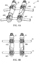
- the spine stabilization system 30 includes at least two flexible connection elements 32 and 34 coupled to at least two transverse rods 36 and 38 which are adapted to be coupled to at least four bone anchors (not shown).
- the flexible connection elements 32 and 34 may advantageously provide desirable properties for bending or twisting that allows the system to accommodate natural spine movement.
- the flexible connection element approximates or resembles a relatively circular cross-section tube or rod.
- a flexible connection element may be other shapes as well.
- the flexible connection element may have a cross-section that approximates or resembles a circle, an oval, an ellipse, or angular geometric shapes such as triangles, squares, rectangles, trapezoids, or the like.
- the flexible connection element may be made from more than one component and the flexible connection element may have complex and varied-cross-sections along its length. It should be understood that in these examples the different types of flexible connection elements described herein may be replaced or interchanged with a flexible connection element having different shapes or configurations, including the many variations described herein.
- FIG. 4B illustrates a top view of the spine stabilization system 30.
- the two flexible connection elements 32 and 34 are coupled to the transverse rods 36 and 38 at anchoring heads 40A-40D.
- the anchoring heads 40A-40D are configured to be a part of the transverse rods 36 and 38.
- the flexible elements 32 and 34 are configured so that these elements can be positioned within the anchoring heads 40A-40D. Locking caps are used to retain the flexible elements within the anchoring heads.
- Figures 4C-4D show additional views of the spine stabilization system 30.
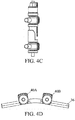
- FIGS. 5A-5C illustrate the spine stabilization system 30 as positioned on a portion of the spine.
- the spine stabilization system is positioned so that the bone anchors 42A-42D are anchored to the pedicle portion of the spine.
- FIGS. 5C and 5D illustrate another embodiment of the spine stabilization system which does not utilize transverse connectors. Rather the spine stabilization system of FIGS. 5C and 5D illustrate flexible connection elements which are independent of each other. Each of the flexible connection elements are anchored to the vertebrae through the use of bone anchors.
- the bone anchors or bone fasteners of the spine stabilization system will be discussed in greater detail below.
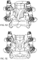
- FIGS. 6A and 6B illustrate the transverse connector 44 of the spine stabilization system of the present invention.
- Each of the transverse connector 44 is configured with at least two anchoring heads 46A and 46B.
- Each of the anchoring heads 46A and 46B is configured in a tulip arrangement for receiving the flexible connection elements.
- FIGS. 6A and 6B illustrates the anchoring heads as tulips, it should be know that any other type of receiving arrangement can be utilized to receiving and retain a portion of the flexible connection element.
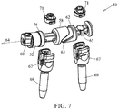
- a bumper or other resiliently compressible member 52 may be disposed over a cord and positioned adjacent an outer end plate 56 of an end portion or spool 58.
- a rigid stop, flange, or end member 60 may be fixedly attached or clamped to a cord on the opposite side of bumper 52 from the spool 58.
- spool 58 may be slidable, movable, or otherwise unconstrained with respect to a cord which passes through the middle portion of the flexible connection element 50.
- bumper 52 may be resiliently compressed between spool 58 and end member 60 when spools 58, 62 are separated or forced apart in the longitudinal direction of axis 64.
- Spool 62 is positioned on the opposing portion of the intermediate portion and is constrains the flexible cord by crimping the core by using a clamping element 65.
- Spools 58 and 62 are configured to be received in the tulip portions 67 of the bone anchors 69.
- Set screws 71 are used to tighten and retain the flexible connection element 50 within the tulip portions 67 of the bone anchors 69.
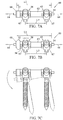
- connection element 50 in a first or neutral position with an overall length L1
- spools 58, 62 may have a first separation distance L2. As shown in FIG. 7A , showing connection element 50 in a first or neutral position with an overall length L1, spools 58, 62 may have a first separation distance L2. As shown in FIG. 7A , showing connection element 50 in a first or neutral position with an overall length L1, spools 58, 62 may have a first separation distance L2. As shown in FIG.
- the second separation distance L3 is greater than L2 which replicates a change in the separation distance of the bone fasteners and the bone segments to which they are attached.
- the flexible element may accommodate up to 8mm of a change in interpedicular distance under flexion. In another variation, up to 4mm of a change in interpedicular distance may be accommodated.
- bumper 52 may be made from the same material as intermediate portion 63. In alternate embodiments, bumper 52 may be made from a different material than intermediate portion 63 or bumper 52 may be made from the same material and have a different hardness or flexibility than intermediate portion.
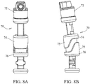
- FIGS. 8A and 8B illustrate the flexible connection element 70 of a spine stabilization system without the anchoring elements as provided in the present invention.
- the flexible connection element 70 includes a bumper 72, floating spool 74, a locking spool 76 which encompass a cord.
- the locking spool 76 and the floating spool 74 are separated by a distance and are configured to have extended side walls 75 for directional control.
- the spools illustrated in FIGS. 8A and 8B have extended side walls and have rounded edges, the spools are not limited by this design.
- FIG. 8B further illustrates a lordotic configuration of the flexible connection element 70. It should be noted that the extended walls of the opposing spools allows for controlled motion and limits the shear translation associated with the movement of the spine.
- FIGS. 9A - 9F other configurations for the spools are illustrated. It should be noted that the extended walls of the spool on the opposing sides may be varied and should not be construed to be limited to the disclosed embodiments. It should be further noted that the extended walls may also be angulated.
- a portion of the locking spool generally comprises a middle portion 80 interposed between outer end plates or flange portions 82.
- a central channel 84 extends axially through spool and is generally configured and dimensioned to accommodate coupling member or cord.
- Middle portion 80 generally comprises a lower clamp body 86 and an upper clamp body 88 selectably moveable with respect to lower clamp body 86 to clamp down and affix cord with respect to spool.
- upper clamp body 88 has a pair of downwardly extending arms 90 having elongated openings 92 configured and dimensioned to receive protrusions or prongs 94, 96 extending outward from lower clamp body 96 so as to allow unidirectional one step clamping or locking of spool with respect to cord.
- Arms 90 are configured and dimensioned to deflect or bend outward slightly to move over protrusions 94, 96.
- protrusions 94, 96 may have a chamfer or angled outer surface 98 and arms 90 may have a chamfered, beveled, or angled inner lower surface 100 to facilitate arm deflection.
- Upper clamp body 98 may be first preassembled onto lower clamp body and positioned in a first position as shown in FIG. 11 .
- the arms 90 may engage upper prongs 94 and deflect outward and over the upper prongs 94 such that the upper prongs extend through openings 90 and provisionally maintain upper clamp body 88 in the first position.
- upper clamp body 88 in the first position, upper clamp body 88 may be relatively loosely affixed to lower clamp body 86 such that a cord extending through middle portion 80 may slide or move with respect to spool.
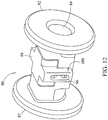
- upper clamp body 88 may be forced downward further onto lower clamp body 86 and positioned in a second or locked position as shown in FIG. 12 .
- the arms 90 may engage lower prongs 96 and deflect outward and over the lower prongs 96 such that the lower prongs extend through openings 90 and maintain the upper clamp body 58 in the second, clamped, or locked position.
- upper clamp body 88 in the second position, upper clamp body 88 may be relatively rigidly affixed to lower clamp body 86 such that a cord extending through middle portion 80 may not slide or move with respect to spool.
- a one step lock or clamping feature may be desirable to allow for tensioning of cord 18 during installation in situ. It should be noted that one may also appreciate that with such a clamping feature integrated into the middle portion 80 of spool, the step of clamping or locking the cord may be accomplished by finally tightening down on a cap or set screw ( FIG. 7 ) . In this regard, the tensioning and final clamping of cord may be accomplished with a familiar procedure common to the installation of contemporary spinal stabilization systems.
- FIGS. 13A-13D another embodiment of a spool is disclosed which generally comprises a post or piercing means to affix cord with respect to spool.
- upper clamp body 88 has a central finger or post 102 extending downwardly from the underside thereof.
- the post 102 may be configured and dimensioned to extend through the cord so as to puncture or pierce through cord and the distal tip 104 of post 102 may enter into a depression 106 provided on the interior of lower clamp body 86.
- a pair of arms 108 extend downward from upper clamp 88 are configured and dimensioned to engage lower clamp body 86 so as to allow unidirectional one step clamping, piercing, and/or locking of spool with respect to cord.
- upper clamp body 88 in a first position, upper clamp body 88 may be spaced from or relatively loosely affixed to lower clamp body 86 such that a cord extending through middle portion 80 may slide or move with respect to spool.
- upper clamp body 88 may be forced downward further onto lower clamp body 86 and positioned in a second or locked position as shown in FIGS. 13C-13D .
- upper clamp body 88 in the second position, upper clamp body 88 may be relatively rigidly affixed to lower clamp body 86 such that a cord extending through middle portion 80 may not slide or move with respect to the spool.
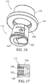
- Clamp assembly 110 for clamping rigid stop, flange, or end portion 112 to cord 114 is shown.
- Clamp assembly 110 generally comprises an annular end body 116 having an end plate or flange 118 and a central cavity 120 configured and dimensioned to house a lower clamp body 122 and an upper clamp body 124.
- Upper and lower clamp bodies 124, 122 have a tapered or partially conically shaped outer surface 126 configured to engage, slide, mate, wedge, or otherwise contact a corresponding opposing tapered or shaped interior wall surface 128 of cavity 120.
- Upper clamp body 124 is movable with respect to lower clamp body 122 to clamp down and affix cord 114 with respect to end body 116.
- upper clamp body 124 has a pair of downwardly extending arms 130 having openings configured and dimensioned to receive protrusions or prongs 132 extending outward from lower clamp body 122 so as to allow unidirectional clamping or locking of end 112 with respect to cord 114. Arms 130 are configured and dimensioned to deflect or bend outward slightly to move over protrusions 132. To affix or clamp cord 114 with respect to end 112, upper clamp body 124 may be assembled over lower clamp body 122 with cord 114 positioned therebetween. As shown in FIG.
- cord 114 may be additionally cinched, clamped, or locked when the assembled upper and lower clamp bodies 124, 122 are positioned within cavity 120 and pulled or forced longitudinally against the tapered inner wall 128 such that the outer surface 126 engages, slides, mates, or wedges thereagainst to force the upper and lower clamp bodies 124, 122 to contract upon cord 18 such that a cord extending through the clamp bodies 88, 90 may not slide or move with respect to end 46.
- a tapered arrangement facilitates secure clamping during natural movement of flexible connection element 40 when installed.
- a shoulder portion 134 of end body 116 may extend outward from flange 84 and may extend into a portion of bumper 136.
- Clamp assembly 140 for clamping rigid stop, flange, or end portion 142 to a cord.
- Clamp assembly 140 generally comprises an annular end body 144 having a central cavity 146 and an end plate or flange 148 configured and dimensioned to house an insertable clamp body 150.
- Clamp assembly 140 generally comprises a post or piercing means to affix cord with respect to end portion 142.
- insertable clamp body 150 has a central finger or post 152 extending downwardly from the underside thereof.
- the post 152 may be configured and dimensioned to extend through the cord so as to puncture or pierce through cord and the distal tip 154 of post 152 may enter into a depression provided on the interior of central cavity 146.
- Insertable clamp body 150 is movable with respect to clamp body 144 to puncture, pierce and/or clamp down and affix cord with respect to end body 144.
- insertable clamp body 150 has a pair of arms 156 configured and dimensioned to engage clamp body 144 so as to allow unidirectional one step clamping, piercing, and/or locking of end portion 142 with respect to the cord. As shown in FIGS.
- insertable clamp body 150 in a first position, insertable clamp body 150 may be spaced from or relatively loosely affixed to end body 144 such that a cord extending through cavity 146 may slide or move with respect to end body 144. To affix or clamp the cord with respect to end portion 142, insertable clamp body 150 may be forced downward further onto end body 144 and positioned in a second or locked position as shown in FIGS. 18C-18D . As shown in FIGS. 18C-18D , in the second position, insertable clamp body 150 may be relatively rigidly affixed to end body 82 such that a cord extending through cavity 146 may not slide or move with respect to end portion 142.
- connection element 160 may be employed in a hybrid procedure employing fusion and dynamic stabilization.
- an elongated end portion 162 may be provided and engaged between vertebrae to be fused and one or more adjacent vertebral levels can be dynamically stabilized with the intermediate portion 164 engaged between end portions 162, 166.
- End portion 162 may have a rod portion 168 integrated into a spool portion 170 and may include a clamping means 172, to affix cord 174 to end portion 162.
- a bumper 176 may be provided adjacent a second end 178 to facilitate elongation of the dynamically stabilized level.
- Connection elements are also contemplated that would provide for multiple spine levels stabilized by fusion and multiple levels dynamically stabilized.
- the bone fasteners included in the disclosed system include any type of fastener connection that may be attached to the spine stabilization system of the invention, while remaining securely fastened onto the intended bone.
- the bone fasteners may include mono-axial screws, polyaxial screws, post-type screws, helical blades, expandable screws, such as Mollie bolt type fasteners, which are inserted or screwed into the bone and expand by way of some type of expansion mechanism, conventional screws, staples, sublaminar hooks, and the like.
- the bone fasteners are coated with any number of suitable osteoinductive or osteoconductive materials to enhance fixation in the bone.
- the bone fasteners are fenestrated to enhance bony ingrowth or to further anchor the fastener to the bone.
- FIGS. 20A-20E illustrate other mechanisms for fastening the present stabilization system to bone.
- the bone fasteners may be made from a host of materials.
- the fasteners may be formed from natural / biological materials, such as allograft, xenograft, and cortical bone.
- the fasteners may also be formed from synthetic bioresorbable materials, such as polyanhydride, polyactide, polyglycolide, polyorthoester, polyphosphazene, calcium phosphate, hydroxyapatite, bioactive glass, tyrosine-derived polycarbonate, and mixtures thereof.
- the fasteners are formed from non-bioresorbable materials including, but not limited to, stainless steel, titanium, titanium alloys, cobalt chrome alloys, shape-memory alloys, and carbon-reinforced polymer composites.
- the fasteners may include growth factors for bone ingrowth and bony attachment, or for soft tissue ingrowth.
- growth factors include insulin-like growth factor 1, basic fibroblast growth factor, transforming growth factor ⁇ -1, platelet-derived growth factor, bone-derived growth factors, arginine, bone morphogenetic protein, LIM mineralization protein, and combinations thereof.
- the flexible connection element may be connected to fasteners in a number of ways, i.e., so that the connection is constrained, unconstrained, articulated, or combinations thereof.
- the end portions may be attached to bone anchors and inserted or installed adjacent a motion segment of the spine.
- the flexible connection element may be inserted into or onto anchor heads, which can be side-loading or top-loading in this aspect of the invention.
- clamping screws may be inserted into or upon the anchor heads and firmly screwed down securing all the connected elements in place. This design would generally allow flexibility between the two bone fasteners.
- the stiffness of the disclosed systems may also be adjusted during the operation and post-operation using a set screw. This would allow surgeons and doctors to make adjustments depending on a specific scenario.
- the system once assembled, may serve a variety of functions in the motion segment unit.
- the system may reduce the load on the degenerative disc and/or facet joints in the motion segment unit.
- the height of the adjacent vertebrae may be restored to eliminate crushing or slipping of the disc therebetween.
- lordosis may be created/ preserved using the disclosed systems in at least one motion segment unit of the spine.
- the stiffness of the motion segment unit may be restored with the implementation of the system of the invention.
- flexible connection elements may be disposed in combination with rods used to make a portion of the system rigid.
- a motion segment neighboring a treated area that has been essentially immobilized with a rigid stabilization system may be supported with a flexible connection element.
Claims (15)
- Rückgratstabilisierungssystem (30) zum flexiblen Stabilisieren eines ersten Rückwirbels mit Bezug auf einen zweiten Rückwirbel, wobei das System Folgendes umfasst:- ein längliches Verbindungselement, das sich von einem ersten Endabschnitt (60) zu einem der zweite Endabschnitt (60) entlang einer Längsachse erstreckt, wobei die ersten und der zweite Endabschnitte (60) durch ein flexibles Kopplungsglied (54) miteinander verbunden sind,- ein längliches Verbindungselement, dieses umfasst: einen ersten Befestigungsabschnitt (58, 74), einen zweiten Befestigungsabschnitt (62, 76), ein erstes elastisches Glied (52), das zwischen dem ersten Endabschnitt (60) und dem ersten Befestigungsabschnitt (58, 74) positioniert ist, und ein zweites elastisches Glied (63), das zwischen dem ersten Befestigungsabschnitt (58, 74) und dem zweiten Befestigungsabschnitt (62, 76) positioniert ist,- wobei das längliche Verbindungselement eine Bewegung des ersten Befestigungsabschnitts (58) relativ zu dem zweiten Befestigungsabschnitt (62) gestattet,- wobei die ersten (58, 74) und zweiten (62, 76) Befestigungsabschnitte das zweite elastische Glied (63) zusammendrücken, wenn die ersten (58, 74) und zweiten (62, 76) Befestigungsabschnitte sich aufeinander zu bewegen,- wobei das erste Ende und die ersten Befestigungsabschnitte (58, 74) das erste elastische Glied (52) zusammendrücken, wenn die ersten (58, 74) und zweiten (62, 76) Befestigungsabschnitte sich voneinander fort erstrecken,- ein erstes Fixierungsglied (42), das den ersten Befestigungsabschnitt mit dem ersten Rückwirbel verbindet; und- ein zweites Fixierungsglied (42), das den zweiten Befestigungsabschnitt mit dem zweiten Rückwirbel verbindet,- wobei ein Teil der ersten (58, 74) und ein Teil der zweiten (62, 76) Befestigungsabschnitte sich an gegenüberliegenden Wänden des länglichen Verbindungselements aufeinander zu erstrecken,- wobei der zweite Befestigungsabschnitt ein Zwischenstück (76) umfasst, das einen mittleren Abschnitt aufweist, der zwischen äußeren Endplatten (82) angeordnet ist,- wobei der mittlere Abschnitt (80) einen oberen Klemmkörper (88) umfasst, der mit Bezug auf einen kleinen Klemmkörper (86) beweglich ist, um eine Kordel mit Bezug auf das Zwischenstück festzuklemmen und zu fixieren.
- System nach Anspruch 1, wobei das Kopplungsglied (54) eine Kordel ist.
- System nach Anspruch 1, wobei der Teil der ersten (58, 74) und der Teil der zweiten (62, 76) Befestigungsabschnitte so konfiguriert sind, dass sie in einer Flanschausrichtung stehen.
- System nach Anspruch 1, wobei der erste Endabschnitt (60) und der zweite Endabschnitt (60) starr an dem Kopplungsglied befestigt sind.
- System nach Anspruch 4, wobei ein Abschnitt der ersten und ein Abschnitt der zweiten Endabschnitte (60) das Kopplungsglied durchdringen.
- System nach Anspruch 4, wobei ein Abschnitt der ersten und ein Abschnitt der zweiten Endabschnitte (60) das Kopplungsglied festklemmen.
- System nach Anspruch 1, wobei das längliche Verbindungselement in einer neutralen Position gekrümmt ist, um sich an die Lordose des Rückgrats anzupassen.
- System nach Anspruch 1, wobei der Teil der ersten (58, 74) und der Teil der zweiten (62, 76) Befestigungsabschnitte in einem Winkel auf dem länglichen Verbindungselement positioniert sind.
- System nach Anspruch 1, wobei das erste Fixierungsglied (42) zum Verbinden des länglichen Verbindungselements mit dem ersten Rückwirbel eine Pedikelschraube ist.
- System nach Anspruch 1, wobei die elastischen Glieder (52, 63) eine Durometer-Härte zwischen etwa Shore 8OA und etwa Shore 10OA aufweisen.
- System nach Anspruch 1, wobei die ersten und zweiten elastischen Glieder (52, 63) aus Materialien bestehen, die eine unterschiedliche Härte aufweisen.
- System nach Anspruch 1, wobei die ersten (58, 74) und zweiten (62, 76) Befestigungsabschnitte Zwischenstücke umfassen.
- System nach Anspruch 1, wobei ein Teil der ersten (58, 74) und ein Teil der zweiten (62, 76) Befestigungsabschnitte sich an gegenüberliegenden Wänden des länglichen Verbindungselements aufeinander zu erstrecken.
- System nach Anspruch 1, wobei das längliche Verbindungselement durch einen Querverbinder (44) mit einem zweiten länglichen Verbindungselement gekoppelt ist.
- System nach Anspruch 1, das des Weiteren einen Stab (168) umfasst, der von oben her in das erste Fixierungsglied (42) eingeführt werden kann.
Applications Claiming Priority (2)
| Application Number | Priority Date | Filing Date | Title |
|---|---|---|---|
| US12/130,388 US8034078B2 (en) | 2008-05-30 | 2008-05-30 | System and method for replacement of spinal motion segment |
| PCT/US2009/045741 WO2009158122A1 (en) | 2008-05-30 | 2009-05-29 | System and method for replacement of spinal motion segment |
Publications (3)
| Publication Number | Publication Date |
|---|---|
| EP2296570A1 EP2296570A1 (de) | 2011-03-23 |
| EP2296570A4 EP2296570A4 (de) | 2013-04-03 |
| EP2296570B1 true EP2296570B1 (de) | 2018-05-09 |
Family
ID=41380728
Family Applications (1)
| Application Number | Title | Priority Date | Filing Date |
|---|---|---|---|
| EP09770657.6A Active EP2296570B1 (de) | 2008-05-30 | 2009-05-29 | System für den ersatz eines wirbelbewegungssegments |
Country Status (3)
| Country | Link |
|---|---|
| US (5) | US8034078B2 (de) |
| EP (1) | EP2296570B1 (de) |
| WO (1) | WO2009158122A1 (de) |
Families Citing this family (84)
| Publication number | Priority date | Publication date | Assignee | Title |
|---|---|---|---|---|
| US7833250B2 (en) | 2004-11-10 | 2010-11-16 | Jackson Roger P | Polyaxial bone screw with helically wound capture connection |
| US8292926B2 (en) | 2005-09-30 | 2012-10-23 | Jackson Roger P | Dynamic stabilization connecting member with elastic core and outer sleeve |
| US20160242816A9 (en) | 2001-05-09 | 2016-08-25 | Roger P. Jackson | Dynamic spinal stabilization assembly with elastic bumpers and locking limited travel closure mechanisms |
| US10258382B2 (en) | 2007-01-18 | 2019-04-16 | Roger P. Jackson | Rod-cord dynamic connection assemblies with slidable bone anchor attachment members along the cord |
| US7862587B2 (en) | 2004-02-27 | 2011-01-04 | Jackson Roger P | Dynamic stabilization assemblies, tool set and method |
| US10729469B2 (en) | 2006-01-09 | 2020-08-04 | Roger P. Jackson | Flexible spinal stabilization assembly with spacer having off-axis core member |
| US8353932B2 (en) | 2005-09-30 | 2013-01-15 | Jackson Roger P | Polyaxial bone anchor assembly with one-piece closure, pressure insert and plastic elongate member |
| US8876868B2 (en) | 2002-09-06 | 2014-11-04 | Roger P. Jackson | Helical guide and advancement flange with radially loaded lip |
| US7621918B2 (en) | 2004-11-23 | 2009-11-24 | Jackson Roger P | Spinal fixation tool set and method |
| US7377923B2 (en) | 2003-05-22 | 2008-05-27 | Alphatec Spine, Inc. | Variable angle spinal screw assembly |
| US7766915B2 (en) | 2004-02-27 | 2010-08-03 | Jackson Roger P | Dynamic fixation assemblies with inner core and outer coil-like member |
| US7776067B2 (en) | 2005-05-27 | 2010-08-17 | Jackson Roger P | Polyaxial bone screw with shank articulation pressure insert and method |
| US8936623B2 (en) | 2003-06-18 | 2015-01-20 | Roger P. Jackson | Polyaxial bone screw assembly |
| US7179261B2 (en) | 2003-12-16 | 2007-02-20 | Depuy Spine, Inc. | Percutaneous access devices and bone anchor assemblies |
| US11419642B2 (en) | 2003-12-16 | 2022-08-23 | Medos International Sarl | Percutaneous access devices and bone anchor assemblies |
| US7527638B2 (en) | 2003-12-16 | 2009-05-05 | Depuy Spine, Inc. | Methods and devices for minimally invasive spinal fixation element placement |
| US8900270B2 (en) * | 2004-02-17 | 2014-12-02 | Gmedelaware 2 Llc | Facet joint replacement instruments and methods |
| US7160300B2 (en) | 2004-02-27 | 2007-01-09 | Jackson Roger P | Orthopedic implant rod reduction tool set and method |
| US11241261B2 (en) | 2005-09-30 | 2022-02-08 | Roger P Jackson | Apparatus and method for soft spinal stabilization using a tensionable cord and releasable end structure |
| US8152810B2 (en) | 2004-11-23 | 2012-04-10 | Jackson Roger P | Spinal fixation tool set and method |
| WO2005092218A1 (en) | 2004-02-27 | 2005-10-06 | Jackson Roger P | Orthopedic implant rod reduction tool set and method |
| US8114158B2 (en) | 2004-08-03 | 2012-02-14 | Kspine, Inc. | Facet device and method |
| US7651502B2 (en) | 2004-09-24 | 2010-01-26 | Jackson Roger P | Spinal fixation tool set and method for rod reduction and fastener insertion |
| US8926672B2 (en) | 2004-11-10 | 2015-01-06 | Roger P. Jackson | Splay control closure for open bone anchor |
| US9393047B2 (en) | 2009-06-15 | 2016-07-19 | Roger P. Jackson | Polyaxial bone anchor with pop-on shank and friction fit retainer with low profile edge lock |
| US8444681B2 (en) | 2009-06-15 | 2013-05-21 | Roger P. Jackson | Polyaxial bone anchor with pop-on shank, friction fit retainer and winged insert |
| US9168069B2 (en) | 2009-06-15 | 2015-10-27 | Roger P. Jackson | Polyaxial bone anchor with pop-on shank and winged insert with lower skirt for engaging a friction fit retainer |
| US20120029568A1 (en) * | 2006-01-09 | 2012-02-02 | Jackson Roger P | Spinal connecting members with radiused rigid sleeves and tensioned cords |
| US9216041B2 (en) | 2009-06-15 | 2015-12-22 | Roger P. Jackson | Spinal connecting members with tensioned cords and rigid sleeves for engaging compression inserts |
| WO2006057837A1 (en) | 2004-11-23 | 2006-06-01 | Jackson Roger P | Spinal fixation tool attachment structure |
| US7901437B2 (en) | 2007-01-26 | 2011-03-08 | Jackson Roger P | Dynamic stabilization member with molded connection |
| US8105368B2 (en) | 2005-09-30 | 2012-01-31 | Jackson Roger P | Dynamic stabilization connecting member with slitted core and outer sleeve |
| US8034078B2 (en) * | 2008-05-30 | 2011-10-11 | Globus Medical, Inc. | System and method for replacement of spinal motion segment |
| EP2088945A4 (de) | 2006-12-08 | 2010-02-17 | Roger P Jackson | Werkzeugsystem für dynamische wirbelsäulenimplantate |
| US8475498B2 (en) | 2007-01-18 | 2013-07-02 | Roger P. Jackson | Dynamic stabilization connecting member with cord connection |
| US8366745B2 (en) | 2007-05-01 | 2013-02-05 | Jackson Roger P | Dynamic stabilization assembly having pre-compressed spacers with differential displacements |
| US11224463B2 (en) | 2007-01-18 | 2022-01-18 | Roger P. Jackson | Dynamic stabilization connecting member with pre-tensioned flexible core member |
| US7842074B2 (en) | 2007-02-26 | 2010-11-30 | Abdou M Samy | Spinal stabilization systems and methods of use |
| EP2142121B1 (de) | 2007-04-30 | 2014-04-16 | Globus Medical, Inc. | Flexibles wirbelsäulenstabilisierungssystem |
| US10383660B2 (en) | 2007-05-01 | 2019-08-20 | Roger P. Jackson | Soft stabilization assemblies with pretensioned cords |
| US8617215B2 (en) * | 2008-05-14 | 2013-12-31 | Warsaw Orthopedic, Inc. | Connecting element and system for flexible spinal stabilization |
| CA2739997C (en) | 2008-08-01 | 2013-08-13 | Roger P. Jackson | Longitudinal connecting member with sleeved tensioned cords |
| US8828058B2 (en) | 2008-11-11 | 2014-09-09 | Kspine, Inc. | Growth directed vertebral fixation system with distractible connector(s) and apical control |
| US8864654B2 (en) | 2010-04-20 | 2014-10-21 | Jeffrey B. Kleiner | Method and apparatus for performing retro peritoneal dissection |
| US9717403B2 (en) | 2008-12-05 | 2017-08-01 | Jeffrey B. Kleiner | Method and apparatus for performing retro peritoneal dissection |
| US8177814B2 (en) * | 2009-02-26 | 2012-05-15 | Life Spine, Inc. | Posterior spinal bridge assembly providing static or dynamic N-level spinal bridge interconnection |
| US8357182B2 (en) | 2009-03-26 | 2013-01-22 | Kspine, Inc. | Alignment system with longitudinal support features |
| US9668771B2 (en) | 2009-06-15 | 2017-06-06 | Roger P Jackson | Soft stabilization assemblies with off-set connector |
| US8998959B2 (en) | 2009-06-15 | 2015-04-07 | Roger P Jackson | Polyaxial bone anchors with pop-on shank, fully constrained friction fit retainer and lock and release insert |
| CN103826560A (zh) | 2009-06-15 | 2014-05-28 | 罗杰.P.杰克逊 | 具有套接杆和带摩擦配合压缩套爪的带翼插件的多轴骨锚 |
| US11229457B2 (en) | 2009-06-15 | 2022-01-25 | Roger P. Jackson | Pivotal bone anchor assembly with insert tool deployment |
| US9211144B2 (en) * | 2009-09-09 | 2015-12-15 | Globus Medical, Inc. | Spine surgery device and method |
| US9168071B2 (en) | 2009-09-15 | 2015-10-27 | K2M, Inc. | Growth modulation system |
| US9814493B2 (en) * | 2009-10-12 | 2017-11-14 | Globus Medical, Inc. | Trans-iliac connector |
| US9113960B2 (en) | 2010-06-08 | 2015-08-25 | Globus Medical, Inc. | Conforming bone stabilization receiver |
| JP2013540468A (ja) | 2010-09-08 | 2013-11-07 | ロジャー・ピー・ジャクソン | 弾性部および非弾性部を有する動的固定化部材 |
| CA2838047A1 (en) | 2011-06-03 | 2012-12-06 | Kspine, Inc. | Spinal correction system actuators |
| US9526535B2 (en) | 2011-11-07 | 2016-12-27 | Morgan Packard Lorio | Methods and apparatuses for delivering a rod to a plurality of pedicle screws |
| US9468469B2 (en) | 2011-11-16 | 2016-10-18 | K2M, Inc. | Transverse coupler adjuster spinal correction systems and methods |
| WO2014172632A2 (en) | 2011-11-16 | 2014-10-23 | Kspine, Inc. | Spinal correction and secondary stabilization |
| US9468468B2 (en) | 2011-11-16 | 2016-10-18 | K2M, Inc. | Transverse connector for spinal stabilization system |
| US9451987B2 (en) | 2011-11-16 | 2016-09-27 | K2M, Inc. | System and method for spinal correction |
| US8920472B2 (en) | 2011-11-16 | 2014-12-30 | Kspine, Inc. | Spinal correction and secondary stabilization |
| US8911479B2 (en) | 2012-01-10 | 2014-12-16 | Roger P. Jackson | Multi-start closures for open implants |
| US9023087B2 (en) * | 2012-11-09 | 2015-05-05 | Blackstone Medical, Inc. | Percutaneous modular head-to-head cross connector |
| DE102012220808A1 (de) | 2012-11-14 | 2014-05-15 | Charité - Universitätsmedizin Berlin | Facettengelenkprothese |
| US8911478B2 (en) | 2012-11-21 | 2014-12-16 | Roger P. Jackson | Splay control closure for open bone anchor |
| US10058354B2 (en) | 2013-01-28 | 2018-08-28 | Roger P. Jackson | Pivotal bone anchor assembly with frictional shank head seating surfaces |
| US8852239B2 (en) | 2013-02-15 | 2014-10-07 | Roger P Jackson | Sagittal angle screw with integral shank and receiver |
| US9610104B2 (en) | 2013-07-25 | 2017-04-04 | Amendia, Inc. | Percutaneous pedicle screw revision system |
| US9468471B2 (en) | 2013-09-17 | 2016-10-18 | K2M, Inc. | Transverse coupler adjuster spinal correction systems and methods |
| US9566092B2 (en) | 2013-10-29 | 2017-02-14 | Roger P. Jackson | Cervical bone anchor with collet retainer and outer locking sleeve |
| US9259249B2 (en) * | 2013-11-26 | 2016-02-16 | Globus Medical, Inc. | Spinous process fixation system and methods thereof |
| US9717533B2 (en) | 2013-12-12 | 2017-08-01 | Roger P. Jackson | Bone anchor closure pivot-splay control flange form guide and advancement structure |
| US9451993B2 (en) | 2014-01-09 | 2016-09-27 | Roger P. Jackson | Bi-radial pop-on cervical bone anchor |
| US9597119B2 (en) | 2014-06-04 | 2017-03-21 | Roger P. Jackson | Polyaxial bone anchor with polymer sleeve |
| US10064658B2 (en) | 2014-06-04 | 2018-09-04 | Roger P. Jackson | Polyaxial bone anchor with insert guides |
| US10285637B1 (en) * | 2014-11-10 | 2019-05-14 | University Of Louisville Research Foundation, Inc. | Apparatus for sensing strain on a spinal fusion rod |
| US10952856B2 (en) * | 2015-04-15 | 2021-03-23 | FreeseTEC Corporation | Spinal fusion containment system |
| EP3100692A1 (de) * | 2015-06-04 | 2016-12-07 | Zimmer Spine | Dynamisches wirbelsäulen-stabilisierungssystem |
| US9603634B1 (en) | 2015-11-13 | 2017-03-28 | Amendia, Inc. | Percutaneous rod-to-rod cross connector |
| US10335207B2 (en) | 2015-12-29 | 2019-07-02 | Nuvasive, Inc. | Spinous process plate fixation assembly |
| US10265103B2 (en) * | 2016-08-18 | 2019-04-23 | Premia Spine Ltd. | Spinal prosthesis with adjustable support element |
| US10874434B2 (en) * | 2017-10-18 | 2020-12-29 | Texas Scottish Rite Hospital For Children | Deformable dynamization device |
Family Cites Families (151)
| Publication number | Priority date | Publication date | Assignee | Title |
|---|---|---|---|---|
| AT292391B (de) | 1967-04-11 | 1971-08-25 | Schuster Wilhelm | Federkörper |
| AT306949B (de) | 1969-12-12 | 1973-04-25 | Wilhelm Schuster Ing | Bespannung für Liege-, Sitz- und Stützflächen aller Art |
| US3851430A (en) | 1973-03-07 | 1974-12-03 | W Schuster | Resilient supporting member |
| US3858578A (en) | 1974-01-21 | 1975-01-07 | Pravel Wilson & Matthews | Surgical retaining device |
| US4112935A (en) | 1976-11-03 | 1978-09-12 | Anvar Latypovich Latypov | Apparatus for surgical treatment of scoliosis |
| US4085744A (en) | 1977-01-31 | 1978-04-25 | David Warren Lewis | Spinal column prostheses orthoses |
| US4269178A (en) | 1979-06-04 | 1981-05-26 | Keene James S | Hook assembly for engaging a spinal column |
| US4409968A (en) | 1980-02-04 | 1983-10-18 | Drummond Denis S | Method and apparatus for engaging a hook assembly to a spinal column |
| US4522198A (en) | 1983-04-18 | 1985-06-11 | Dacomed Corporation | Penile prosthesis |
| US4517967A (en) | 1983-04-18 | 1985-05-21 | Dacomed Corporation | Penile prosthesis |
| FR2545350B1 (fr) | 1983-05-04 | 1985-08-23 | Cotrel Yves | Dispositif pour l'etaiement du rachis |
| US4619251A (en) | 1984-04-26 | 1986-10-28 | Dacomed Corporation | Penile prosthesis having an actuator means interacting with a member and articulated column |
| US4666428A (en) | 1984-10-23 | 1987-05-19 | Stefano Mattioli | Semi-rigid penial prosthesis for the treatment of impotence in the erection |
| US4911346A (en) | 1984-11-23 | 1990-03-27 | Shallman Richard W | Flexible, segmental backpack frame |
| DE3614101C1 (de) | 1986-04-25 | 1987-10-22 | Juergen Prof Dr Med Harms | Pedikelschraube |
| US4881531A (en) | 1986-11-21 | 1989-11-21 | Dacomed Corporation | Position stable segmented column penile prosthesis |
| US4790303A (en) | 1987-03-11 | 1988-12-13 | Acromed Corporation | Apparatus and method for securing bone graft |
| DE8704901U1 (de) | 1987-04-02 | 1987-07-23 | Kluger, Patrick, Dr.Med., 3590 Bad Wildungen, De | |
| DE3800052A1 (de) | 1987-07-08 | 1989-07-13 | Harms Juergen | Positionierungsschraube |
| US5197983A (en) | 1988-04-19 | 1993-03-30 | W. L. Gore & Associates, Inc. | Ligament and tendon prosthesis |
| GB2233928B (en) * | 1989-05-23 | 1992-12-23 | Brother Ind Ltd | Apparatus and method for forming three-dimensional article |
| US5344422A (en) | 1989-10-30 | 1994-09-06 | Synthes (U.S.A.) | Pedicular screw clamp |
| CA2035348C (fr) | 1990-02-08 | 2000-05-16 | Jean-Louis Vignaud | Dispositif de fixation orientable de tiges d'osteosynthese rachidienne |
| WO1991016020A1 (en) | 1990-04-26 | 1991-10-31 | Danninger Medical Technology, Inc. | Transpedicular screw system and method of use |
| US5050592A (en) | 1990-05-07 | 1991-09-24 | Raul Olmedo | Penile prosthesis |
| FR2666981B1 (fr) | 1990-09-21 | 1993-06-25 | Commarmond Jacques | Ligament synthetique vertebral. |
| CH685850A5 (de) | 1990-11-26 | 1995-10-31 | Synthes Ag | Verankerungseinrichtung |
| FR2676911B1 (fr) | 1991-05-30 | 1998-03-06 | Psi Ste Civile Particuliere | Dispositif de stabilisation intervertebrale a amortisseurs. |
| US5209752A (en) | 1991-12-04 | 1993-05-11 | Danek Medical, Inc. | Lateral offset connector for spinal implant system |
| US5246442A (en) | 1991-12-31 | 1993-09-21 | Danek Medical, Inc. | Spinal hook |
| US5409488A (en) * | 1992-01-16 | 1995-04-25 | Ulrich; Heinrich | Spondylodesis implant |
| US5261909A (en) | 1992-02-18 | 1993-11-16 | Danek Medical, Inc. | Variable angle screw for spinal implant system |
| DE59301618D1 (de) | 1992-06-04 | 1996-03-28 | Synthes Ag | Osteosynthetisches Befestigungselement |
| FR2692952B1 (fr) | 1992-06-25 | 1996-04-05 | Psi | Amortisseurs perfectionnes a limite de deplacement. |
| US5281222A (en) | 1992-06-30 | 1994-01-25 | Zimmer, Inc. | Spinal implant system |
| ZA937672B (en) * | 1992-10-22 | 1994-05-16 | Danek Medical Inc | Spinal rod transverse connector for supporting vertebral fixation elements |
| FR2697743B1 (fr) | 1992-11-09 | 1995-01-27 | Fabrication Mat Orthopedique S | Dispositif d'ostéosynthèse rachidienne applicable notamment aux vertèbres dégénératives. |
| US5615965A (en) | 1992-11-10 | 1997-04-01 | Sofamor S.N.C. | Device for interconnecting an elongate element and a support for said element |
| FR2697992B1 (fr) | 1992-11-18 | 1994-12-30 | Eurosurgical | Dispositif de fixation sur une tige d'un organe, en particulier pour une instrumentation d'orthopédie rachidienne. |
| DE4243951C2 (de) | 1992-12-23 | 1997-07-03 | Plus Endoprothetik Ag | Vorrichtung zur Versteifung eines aus wenigstens zwei Wirbeln bestehenden Wirbelsäulenabschnitts |
| US5306275A (en) | 1992-12-31 | 1994-04-26 | Bryan Donald W | Lumbar spine fixation apparatus and method |
| DE4303770C1 (de) | 1993-02-09 | 1994-05-26 | Plus Endoprothetik Ag Rotkreuz | Vorrichtung zur Versteifung und/oder Korrektur eines Wirbelsäulenabschnitts |
| FR2701650B1 (fr) | 1993-02-17 | 1995-05-24 | Psi | Amortisseur double pour la stabilisation intervertébrale. |
| US5282801A (en) | 1993-02-17 | 1994-02-01 | Danek Medical, Inc. | Top tightening clamp assembly for a spinal fixation system |
| FR2702362B3 (fr) | 1993-02-24 | 1995-04-14 | Soprane Sa | Fixateur pour les ostéosynthèses du rachis lombo-sacré. |
| US5415661A (en) | 1993-03-24 | 1995-05-16 | University Of Miami | Implantable spinal assist device |
| US6077262A (en) | 1993-06-04 | 2000-06-20 | Synthes (U.S.A.) | Posterior spinal implant |
| FR2709246B1 (fr) | 1993-08-27 | 1995-09-29 | Martin Jean Raymond | Orthèse vertébrale implantée dynamique. |
| US5611800A (en) | 1994-02-15 | 1997-03-18 | Alphatec Manufacturing, Inc. | Spinal fixation system |
| US5601552A (en) | 1994-03-18 | 1997-02-11 | Sofamor, S.N.C. | Fixing device for a rigid transverse connection device between rods of a spinal osteosynthesis system |
| US5643259A (en) | 1994-03-31 | 1997-07-01 | Ricardo C. Sasso | Spine fixation instrumentation |
| ES2081766B1 (es) | 1994-05-13 | 1996-10-01 | Bilbao Ortiz De Zarate Jose Ra | Sistema de fijacion vertebral cervical por via posterior. |
| US5560775A (en) | 1994-05-23 | 1996-10-01 | Advanced Micro Devices, Inc. | Quartz marking system |
| WO1998008454A1 (en) | 1994-05-25 | 1998-03-05 | Jackson Roger P | Apparatus and method for spinal fixation and correction of spinal deformities |
| EP0689798B1 (de) | 1994-06-30 | 2000-10-18 | Sulzer Orthopädie AG | Vorrichtung zum Verbinden von Wirbelknochen |
| US5468213A (en) | 1994-09-22 | 1995-11-21 | American Medical Systems, Inc. | Mechanical penile prosthesis |
| US5591164A (en) | 1994-12-22 | 1997-01-07 | Zimmer, Inc. | External fixation apparatus and system |
| FR2731344B1 (fr) | 1995-03-06 | 1997-08-22 | Dimso Sa | Instrumentation rachidienne notamment pour tige |
| US5545167A (en) | 1995-04-11 | 1996-08-13 | Lin; Chih-I | Retaining mechanism of vertebral fixation rod |
| US5947966A (en) | 1995-06-06 | 1999-09-07 | Sdgi Holdings, Inc. | Device for linking adjacent rods in spinal instrumentation |
| US5562663A (en) | 1995-06-07 | 1996-10-08 | Danek Medical, Inc. | Implant interconnection mechanism |
| US5645544A (en) | 1995-09-13 | 1997-07-08 | Danek Medical, Inc. | Variable angle extension rod |
| US5752955A (en) | 1995-10-30 | 1998-05-19 | Fastenetix, L.L.C. | Sliding shaft variable length cross-link device for use with dual rod apparatus |
| DE19617362C2 (de) | 1996-04-30 | 1999-06-10 | Harms Juergen | Verankerungselement |
| FR2751864B1 (fr) | 1996-08-01 | 1999-04-30 | Graf Henry | Dispositif pour relier et assister mecaniquement des vertebres entre elles |
| JP2871620B2 (ja) | 1996-09-06 | 1999-03-17 | 株式会社ロバート・リード商会 | 骨固定装置 |
| US5810815A (en) | 1996-09-20 | 1998-09-22 | Morales; Jose A. | Surgical apparatus for use in the treatment of spinal deformities |
| CA2264672C (en) | 1996-10-24 | 2010-11-30 | Spinal Concepts, Inc. | Method and apparatus for spinal fixation |
| US6416515B1 (en) | 1996-10-24 | 2002-07-09 | Spinal Concepts, Inc. | Spinal fixation system |
| FR2755844B1 (fr) | 1996-11-15 | 1999-01-29 | Stryker France Sa | Systeme d'osteosynthese a deformation elastique pour colonne vertebrale |
| US5782833A (en) | 1996-12-20 | 1998-07-21 | Haider; Thomas T. | Pedicle screw system for osteosynthesis |
| US5752957A (en) | 1997-02-12 | 1998-05-19 | Third Millennium Engineering, Llc | Polyaxial mechanism for use with orthopaedic implant devices |
| FR2761590B1 (fr) | 1997-04-04 | 1999-08-20 | Stryker France Sa | Dispositif d'osteosynthese du rachis a fixation de tige intervertebrale desaxee |
| US6290700B1 (en) | 1997-07-31 | 2001-09-18 | Plus Endoprothetik Ag | Device for stiffening and/or correcting a vertebral column or such like |
| FR2767263B1 (fr) | 1997-08-13 | 1999-10-01 | Aesculap Jbs | Pince pour systeme d'osteosynthese vertebrale |
| FR2771280B1 (fr) | 1997-11-26 | 2001-01-26 | Albert P Alby | Dispositif de liaison vertebrale resilient |
| GB9725929D0 (en) * | 1997-12-05 | 1998-02-04 | Xaar Plc | Radiation curable ink jet ink compositions |
| US6010503A (en) | 1998-04-03 | 2000-01-04 | Spinal Innovations, Llc | Locking mechanism |
| US6296644B1 (en) | 1998-08-26 | 2001-10-02 | Jean Saurat | Spinal instrumentation system with articulated modules |
| US5910142A (en) | 1998-10-19 | 1999-06-08 | Bones Consulting, Llc | Polyaxial pedicle screw having a rod clamping split ferrule coupling element |
| US5944719A (en) | 1998-11-10 | 1999-08-31 | Millennium Devices, L.L.C. | External fixator |
| US6234705B1 (en) | 1999-04-06 | 2001-05-22 | Synthes (Usa) | Transconnector for coupling spinal rods |
| US6162223A (en) | 1999-04-09 | 2000-12-19 | Smith & Nephew, Inc. | Dynamic wrist fixation apparatus for early joint motion in distal radius fractures |
| US6296643B1 (en) | 1999-04-23 | 2001-10-02 | Sdgi Holdings, Inc. | Device for the correction of spinal deformities through vertebral body tethering without fusion |
| US6328739B1 (en) | 1999-05-04 | 2001-12-11 | Industrial Technology Research Institute | Enhanced spine fixation apparatus |
| US6235028B1 (en) * | 2000-02-14 | 2001-05-22 | Sdgi Holdings, Inc. | Surgical guide rod |
| US20020133155A1 (en) | 2000-02-25 | 2002-09-19 | Ferree Bret A. | Cross-coupled vertebral stabilizers incorporating spinal motion restriction |
| US6524310B1 (en) | 2000-08-18 | 2003-02-25 | Blackstone Medical, Inc. | Surgical cross-connecting apparatus having locking lever |
| US6485491B1 (en) | 2000-09-15 | 2002-11-26 | Sdgi Holdings, Inc. | Posterior fixation system |
| ATE296580T1 (de) | 2000-09-18 | 2005-06-15 | Zimmer Gmbh | Pedikelschraube für intervertebrale stützelemente |
| FR2819711B1 (fr) | 2001-01-23 | 2003-08-01 | Stryker Spine Sa | Systeme de reglage en position pour instrument de chirurgie rachidienne |
| US6827743B2 (en) | 2001-02-28 | 2004-12-07 | Sdgi Holdings, Inc. | Woven orthopedic implants |
| US10258382B2 (en) * | 2007-01-18 | 2019-04-16 | Roger P. Jackson | Rod-cord dynamic connection assemblies with slidable bone anchor attachment members along the cord |
| US6783527B2 (en) | 2001-10-30 | 2004-08-31 | Sdgi Holdings, Inc. | Flexible spinal stabilization system and method |
| US6966910B2 (en) | 2002-04-05 | 2005-11-22 | Stephen Ritland | Dynamic fixation device and method of use |
| US20030220643A1 (en) | 2002-05-24 | 2003-11-27 | Ferree Bret A. | Devices to prevent spinal extension |
| GB2396331A (en) * | 2002-12-20 | 2004-06-23 | Inca Digital Printers Ltd | Curing ink |
| US7037952B2 (en) * | 2002-08-02 | 2006-05-02 | Seiren Co., Ltd. | Ultraviolet ray curable ink, ink composition for ink jet and process for preparing ink jet printed matter using the same |
| US7306603B2 (en) | 2002-08-21 | 2007-12-11 | Innovative Spinal Technologies | Device and method for percutaneous placement of lumbar pedicle screws and connecting rods |
| US20040143264A1 (en) | 2002-08-23 | 2004-07-22 | Mcafee Paul C. | Metal-backed UHMWPE rod sleeve system preserving spinal motion |
| US7473267B2 (en) | 2003-04-25 | 2009-01-06 | Warsaw Orthopedic, Inc. | System and method for minimally invasive posterior fixation |
| WO2004096066A2 (en) | 2003-04-25 | 2004-11-11 | Kitchen Michael S | Spinal curvature correction device |
| US20050182401A1 (en) * | 2003-05-02 | 2005-08-18 | Timm Jens P. | Systems and methods for spine stabilization including a dynamic junction |
| US6986771B2 (en) | 2003-05-23 | 2006-01-17 | Globus Medical, Inc. | Spine stabilization system |
| US7785351B2 (en) | 2003-08-05 | 2010-08-31 | Flexuspine, Inc. | Artificial functional spinal implant unit system and method for use |
| US7938858B2 (en) * | 2003-09-15 | 2011-05-10 | Warsaw Orthopedic, Inc. | Spinal implant system |
| US7763052B2 (en) | 2003-12-05 | 2010-07-27 | N Spine, Inc. | Method and apparatus for flexible fixation of a spine |
| US7618442B2 (en) * | 2003-10-21 | 2009-11-17 | Theken Spine, Llc | Implant assembly and method for use in an internal structure stabilization system |
| US7695517B2 (en) | 2003-12-10 | 2010-04-13 | Axiomed Spine Corporation | Apparatus for replacing a damaged spinal disc |
| US20050203511A1 (en) * | 2004-03-02 | 2005-09-15 | Wilson-Macdonald James | Orthopaedics device and system |
| DE102004011685A1 (de) | 2004-03-09 | 2005-09-29 | Biedermann Motech Gmbh | Stabförmiges Element für die Anwendung in der Wirbelsäulen- oder Unfallchirurgie und Stabilisierungseinrichtung mit einem solchen stabförmigen Element |
| US8034085B2 (en) * | 2004-05-28 | 2011-10-11 | Depuy Spine, Inc. | Non-fusion spinal correction systems and methods |
| US7931675B2 (en) | 2004-06-23 | 2011-04-26 | Yale University | Dynamic stabilization device including overhanging stabilizing member |
| US7854752B2 (en) | 2004-08-09 | 2010-12-21 | Theken Spine, Llc | System and method for dynamic skeletal stabilization |
| US8123782B2 (en) * | 2004-10-20 | 2012-02-28 | Vertiflex, Inc. | Interspinous spacer |
| JP4744131B2 (ja) * | 2004-12-09 | 2011-08-10 | セーレン株式会社 | 紫外線硬化型インクジェットインク |
| EP1719468A1 (de) * | 2004-12-17 | 2006-11-08 | Zimmer GmbH | Intervertebrales Stabilisierungssystem |
| US20060149242A1 (en) | 2004-12-17 | 2006-07-06 | Gary Kraus | Spinal stabilization systems supplemented with diagnostically opaque materials |
| US7294129B2 (en) * | 2005-02-18 | 2007-11-13 | Ebi, L.P. | Spinal fixation device and associated method |
| US7604654B2 (en) * | 2005-02-22 | 2009-10-20 | Stryker Spine | Apparatus and method for dynamic vertebral stabilization |
| US7967844B2 (en) * | 2005-06-10 | 2011-06-28 | Depuy Spine, Inc. | Multi-level posterior dynamic stabilization systems and methods |
| CA2614887A1 (en) * | 2005-07-25 | 2007-02-01 | Toyo Ink Mfg. Co., Ltd. | Active energy beam-curable ink for injet printing |
| US7713288B2 (en) * | 2005-08-03 | 2010-05-11 | Applied Spine Technologies, Inc. | Spring junction and assembly methods for spinal device |
| US20080140076A1 (en) * | 2005-09-30 | 2008-06-12 | Jackson Roger P | Dynamic stabilization connecting member with slitted segment and surrounding external elastomer |
| GB0519941D0 (en) * | 2005-09-30 | 2005-11-09 | Xennia Technology Ltd | Inkjet printing |
| US8137385B2 (en) * | 2005-10-31 | 2012-03-20 | Stryker Spine | System and method for dynamic vertebral stabilization |
| US8034078B2 (en) * | 2008-05-30 | 2011-10-11 | Globus Medical, Inc. | System and method for replacement of spinal motion segment |
| US8088148B2 (en) * | 2006-02-24 | 2012-01-03 | Medical Design, LLC | Dynamic/static facet fixation device and method |
| US8048134B2 (en) * | 2006-04-06 | 2011-11-01 | Andrew K. Palmer | Active compression to facilitate healing of bones |
| US7942905B2 (en) | 2006-04-20 | 2011-05-17 | Warsaw Orthopedic, Inc. | Vertebral stabilizer |
| US7794387B2 (en) * | 2006-04-26 | 2010-09-14 | Medtronic, Inc. | Methods and devices for stabilizing tissue |
| US7785350B2 (en) | 2006-05-08 | 2010-08-31 | Warsaw Orthopedic, Inc. | Load bearing flexible spinal connecting element |
| US7927356B2 (en) * | 2006-07-07 | 2011-04-19 | Warsaw Orthopedic, Inc. | Dynamic constructs for spinal stabilization |
| AU2007277124A1 (en) | 2006-07-24 | 2008-01-31 | Nuvasive, Inc. | Systems and methods for dynamic spinal stabilization |
| US7828824B2 (en) * | 2006-12-15 | 2010-11-09 | Depuy Spine, Inc. | Facet joint prosthesis |
| US20080154308A1 (en) | 2006-12-21 | 2008-06-26 | Warsaw Orthopedic, Inc. | Spinal fixation system |
| US8029544B2 (en) | 2007-01-02 | 2011-10-04 | Zimmer Spine, Inc. | Spine stiffening device |
| US7985785B2 (en) * | 2007-01-15 | 2011-07-26 | Fujifilm Corporation | Ink composition and inkjet recording method using the same |
| US8109975B2 (en) | 2007-01-30 | 2012-02-07 | Warsaw Orthopedic, Inc. | Collar bore configuration for dynamic spinal stabilization assembly |
| US8029547B2 (en) * | 2007-01-30 | 2011-10-04 | Warsaw Orthopedic, Inc. | Dynamic spinal stabilization assembly with sliding collars |
| US20080195153A1 (en) | 2007-02-08 | 2008-08-14 | Matthew Thompson | Dynamic spinal deformity correction |
| ES2392351T3 (es) * | 2007-02-23 | 2012-12-07 | Biedermann Technologies Gmbh & Co. Kg | Dispositivo para estabilizar vértebras |
| US8292929B2 (en) * | 2007-03-16 | 2012-10-23 | Zimmer Spine, Inc. | Dynamic spinal stabilization system and method of using the same |
| US8057516B2 (en) | 2007-03-21 | 2011-11-15 | Zimmer Spine, Inc. | Spinal stabilization system with rigid and flexible elements |
| US7922725B2 (en) | 2007-04-19 | 2011-04-12 | Zimmer Spine, Inc. | Method and associated instrumentation for installation of spinal dynamic stabilization system |
| EP2142121B1 (de) * | 2007-04-30 | 2014-04-16 | Globus Medical, Inc. | Flexibles wirbelsäulenstabilisierungssystem |
| US20080312655A1 (en) * | 2007-06-14 | 2008-12-18 | X-Spine Systems, Inc. | Polyaxial screw system and method having a hinged receiver |
| US8292925B2 (en) * | 2007-06-19 | 2012-10-23 | Zimmer Spine, Inc. | Flexible member with variable flexibility for providing dynamic stability to a spine |
| US8425564B2 (en) * | 2008-01-03 | 2013-04-23 | P. Douglas Kiester | Spine reconstruction rod extender |
| US8021393B2 (en) * | 2008-12-12 | 2011-09-20 | Globus Medical, Inc. | Lateral spinous process spacer with deployable wings |
| US20140148854A1 (en) * | 2012-11-28 | 2014-05-29 | Zimmer Spine, Inc. | Vertebral fixation system |
-
2008
- 2008-05-30 US US12/130,388 patent/US8034078B2/en active Active
-
2009
- 2009-05-29 WO PCT/US2009/045741 patent/WO2009158122A1/en active Application Filing
- 2009-05-29 EP EP09770657.6A patent/EP2296570B1/de active Active
-
2011
- 2011-09-07 US US13/226,898 patent/US9179940B2/en active Active
-
2015
- 2015-10-06 US US14/875,749 patent/US9999446B2/en active Active
-
2018
- 2018-05-22 US US15/986,130 patent/US10695098B2/en active Active
-
2020
- 2020-06-02 US US16/890,279 patent/US11564713B2/en active Active
Non-Patent Citations (1)
| Title |
|---|
| None * |
Also Published As
| Publication number | Publication date |
|---|---|
| US9179940B2 (en) | 2015-11-10 |
| US20200289162A1 (en) | 2020-09-17 |
| US20180263661A1 (en) | 2018-09-20 |
| US11564713B2 (en) | 2023-01-31 |
| US10695098B2 (en) | 2020-06-30 |
| US20160022318A1 (en) | 2016-01-28 |
| US9999446B2 (en) | 2018-06-19 |
| US20120053634A1 (en) | 2012-03-01 |
| WO2009158122A1 (en) | 2009-12-30 |
| US8034078B2 (en) | 2011-10-11 |
| US20090299411A1 (en) | 2009-12-03 |
| EP2296570A4 (de) | 2013-04-03 |
| EP2296570A1 (de) | 2011-03-23 |
Similar Documents
| Publication | Publication Date | Title |
|---|---|---|
| US11564713B2 (en) | System and method for replacement of spinal motion segment | |
| US9636145B2 (en) | Flexible spine stabilization system | |
| US8882817B2 (en) | Spinal fixation system | |
| US7967847B2 (en) | Spinal stabilization and reconstruction with fusion rods | |
| US8979898B2 (en) | Iliosacral polyaxial screw | |
| US20110230917A1 (en) | Adjustable multi-axial spinal coupling assemblies | |
| US20070233090A1 (en) | Aligning cross-connector | |
| US20130103088A1 (en) | Segmental Spinous Process Anchor System and Methods of Use | |
| US9962191B2 (en) | Spinal implant and methods of use thereof | |
| US20170258497A1 (en) | Bone Anchor with Deployable Purchase Element | |
| US20200289164A1 (en) | Flexible spine stabilization system | |
| US9095378B2 (en) | Spinal stabilization system | |
| AU2013206445A1 (en) | Bottom loading multi-axial screw assembly |
Legal Events
| Date | Code | Title | Description |
|---|---|---|---|
| PUAI | Public reference made under article 153(3) epc to a published international application that has entered the european phase |
Free format text: ORIGINAL CODE: 0009012 |
|
| 17P | Request for examination filed |
Effective date: 20101228 |
|
| AK | Designated contracting states |
Kind code of ref document: A1 Designated state(s): AT BE BG CH CY CZ DE DK EE ES FI FR GB GR HR HU IE IS IT LI LT LU LV MC MK MT NL NO PL PT RO SE SI SK TR |
|
| AX | Request for extension of the european patent |
Extension state: AL BA RS |
|
| DAX | Request for extension of the european patent (deleted) | ||
| A4 | Supplementary search report drawn up and despatched |
Effective date: 20130306 |
|
| RIC1 | Information provided on ipc code assigned before grant |
Ipc: A61B 17/70 20060101AFI20130228BHEP |
|
| GRAP | Despatch of communication of intention to grant a patent |
Free format text: ORIGINAL CODE: EPIDOSNIGR1 |
|
| INTG | Intention to grant announced |
Effective date: 20180108 |
|
| GRAS | Grant fee paid |
Free format text: ORIGINAL CODE: EPIDOSNIGR3 |
|
| GRAA | (expected) grant |
Free format text: ORIGINAL CODE: 0009210 |
|
| AK | Designated contracting states |
Kind code of ref document: B1 Designated state(s): AT BE BG CH CY CZ DE DK EE ES FI FR GB GR HR HU IE IS IT LI LT LU LV MC MK MT NL NO PL PT RO SE SI SK TR |
|
| REG | Reference to a national code |
Ref country code: GB Ref legal event code: FG4D |
|
| REG | Reference to a national code |
Ref country code: CH Ref legal event code: EP Ref country code: AT Ref legal event code: REF Ref document number: 996810 Country of ref document: AT Kind code of ref document: T Effective date: 20180515 |
|
| REG | Reference to a national code |
Ref country code: DE Ref legal event code: R096 Ref document number: 602009052230 Country of ref document: DE Ref country code: IE Ref legal event code: FG4D |
|
| REG | Reference to a national code |
Ref country code: NL Ref legal event code: MP Effective date: 20180509 |
|
| REG | Reference to a national code |
Ref country code: LT Ref legal event code: MG4D |
|
| PG25 | Lapsed in a contracting state [announced via postgrant information from national office to epo] |
Ref country code: SE Free format text: LAPSE BECAUSE OF FAILURE TO SUBMIT A TRANSLATION OF THE DESCRIPTION OR TO PAY THE FEE WITHIN THE PRESCRIBED TIME-LIMIT Effective date: 20180509 Ref country code: ES Free format text: LAPSE BECAUSE OF FAILURE TO SUBMIT A TRANSLATION OF THE DESCRIPTION OR TO PAY THE FEE WITHIN THE PRESCRIBED TIME-LIMIT Effective date: 20180509 Ref country code: LT Free format text: LAPSE BECAUSE OF FAILURE TO SUBMIT A TRANSLATION OF THE DESCRIPTION OR TO PAY THE FEE WITHIN THE PRESCRIBED TIME-LIMIT Effective date: 20180509 Ref country code: NO Free format text: LAPSE BECAUSE OF FAILURE TO SUBMIT A TRANSLATION OF THE DESCRIPTION OR TO PAY THE FEE WITHIN THE PRESCRIBED TIME-LIMIT Effective date: 20180809 Ref country code: BG Free format text: LAPSE BECAUSE OF FAILURE TO SUBMIT A TRANSLATION OF THE DESCRIPTION OR TO PAY THE FEE WITHIN THE PRESCRIBED TIME-LIMIT Effective date: 20180809 Ref country code: FI Free format text: LAPSE BECAUSE OF FAILURE TO SUBMIT A TRANSLATION OF THE DESCRIPTION OR TO PAY THE FEE WITHIN THE PRESCRIBED TIME-LIMIT Effective date: 20180509 |
|
| PG25 | Lapsed in a contracting state [announced via postgrant information from national office to epo] |
Ref country code: GR Free format text: LAPSE BECAUSE OF FAILURE TO SUBMIT A TRANSLATION OF THE DESCRIPTION OR TO PAY THE FEE WITHIN THE PRESCRIBED TIME-LIMIT Effective date: 20180810 Ref country code: HR Free format text: LAPSE BECAUSE OF FAILURE TO SUBMIT A TRANSLATION OF THE DESCRIPTION OR TO PAY THE FEE WITHIN THE PRESCRIBED TIME-LIMIT Effective date: 20180509 Ref country code: NL Free format text: LAPSE BECAUSE OF FAILURE TO SUBMIT A TRANSLATION OF THE DESCRIPTION OR TO PAY THE FEE WITHIN THE PRESCRIBED TIME-LIMIT Effective date: 20180509 Ref country code: LV Free format text: LAPSE BECAUSE OF FAILURE TO SUBMIT A TRANSLATION OF THE DESCRIPTION OR TO PAY THE FEE WITHIN THE PRESCRIBED TIME-LIMIT Effective date: 20180509 |
|
| REG | Reference to a national code |
Ref country code: CH Ref legal event code: PL |
|
| REG | Reference to a national code |
Ref country code: AT Ref legal event code: MK05 Ref document number: 996810 Country of ref document: AT Kind code of ref document: T Effective date: 20180509 |
|
| REG | Reference to a national code |
Ref country code: BE Ref legal event code: MM Effective date: 20180531 |
|
| PG25 | Lapsed in a contracting state [announced via postgrant information from national office to epo] |
Ref country code: AT Free format text: LAPSE BECAUSE OF FAILURE TO SUBMIT A TRANSLATION OF THE DESCRIPTION OR TO PAY THE FEE WITHIN THE PRESCRIBED TIME-LIMIT Effective date: 20180509 Ref country code: DK Free format text: LAPSE BECAUSE OF FAILURE TO SUBMIT A TRANSLATION OF THE DESCRIPTION OR TO PAY THE FEE WITHIN THE PRESCRIBED TIME-LIMIT Effective date: 20180509 Ref country code: EE Free format text: LAPSE BECAUSE OF FAILURE TO SUBMIT A TRANSLATION OF THE DESCRIPTION OR TO PAY THE FEE WITHIN THE PRESCRIBED TIME-LIMIT Effective date: 20180509 Ref country code: SK Free format text: LAPSE BECAUSE OF FAILURE TO SUBMIT A TRANSLATION OF THE DESCRIPTION OR TO PAY THE FEE WITHIN THE PRESCRIBED TIME-LIMIT Effective date: 20180509 Ref country code: RO Free format text: LAPSE BECAUSE OF FAILURE TO SUBMIT A TRANSLATION OF THE DESCRIPTION OR TO PAY THE FEE WITHIN THE PRESCRIBED TIME-LIMIT Effective date: 20180509 Ref country code: CZ Free format text: LAPSE BECAUSE OF FAILURE TO SUBMIT A TRANSLATION OF THE DESCRIPTION OR TO PAY THE FEE WITHIN THE PRESCRIBED TIME-LIMIT Effective date: 20180509 Ref country code: PL Free format text: LAPSE BECAUSE OF FAILURE TO SUBMIT A TRANSLATION OF THE DESCRIPTION OR TO PAY THE FEE WITHIN THE PRESCRIBED TIME-LIMIT Effective date: 20180509 |
|
| REG | Reference to a national code |
Ref country code: DE Ref legal event code: R097 Ref document number: 602009052230 Country of ref document: DE |
|
| REG | Reference to a national code |
Ref country code: IE Ref legal event code: MM4A |
|
| PG25 | Lapsed in a contracting state [announced via postgrant information from national office to epo] |
Ref country code: LI Free format text: LAPSE BECAUSE OF NON-PAYMENT OF DUE FEES Effective date: 20180531 Ref country code: CH Free format text: LAPSE BECAUSE OF NON-PAYMENT OF DUE FEES Effective date: 20180531 Ref country code: IT Free format text: LAPSE BECAUSE OF FAILURE TO SUBMIT A TRANSLATION OF THE DESCRIPTION OR TO PAY THE FEE WITHIN THE PRESCRIBED TIME-LIMIT Effective date: 20180509 |
|
| PLBE | No opposition filed within time limit |
Free format text: ORIGINAL CODE: 0009261 |
|
| STAA | Information on the status of an ep patent application or granted ep patent |
Free format text: STATUS: NO OPPOSITION FILED WITHIN TIME LIMIT |
|
| PG25 | Lapsed in a contracting state [announced via postgrant information from national office to epo] |
Ref country code: LU Free format text: LAPSE BECAUSE OF NON-PAYMENT OF DUE FEES Effective date: 20180529 Ref country code: MC Free format text: LAPSE BECAUSE OF FAILURE TO SUBMIT A TRANSLATION OF THE DESCRIPTION OR TO PAY THE FEE WITHIN THE PRESCRIBED TIME-LIMIT Effective date: 20180509 |
|
| 26N | No opposition filed |
Effective date: 20190212 |
|
| PG25 | Lapsed in a contracting state [announced via postgrant information from national office to epo] |
Ref country code: FR Free format text: LAPSE BECAUSE OF NON-PAYMENT OF DUE FEES Effective date: 20180709 Ref country code: IE Free format text: LAPSE BECAUSE OF NON-PAYMENT OF DUE FEES Effective date: 20180529 |
|
| PG25 | Lapsed in a contracting state [announced via postgrant information from national office to epo] |
Ref country code: BE Free format text: LAPSE BECAUSE OF NON-PAYMENT OF DUE FEES Effective date: 20180531 Ref country code: SI Free format text: LAPSE BECAUSE OF FAILURE TO SUBMIT A TRANSLATION OF THE DESCRIPTION OR TO PAY THE FEE WITHIN THE PRESCRIBED TIME-LIMIT Effective date: 20180509 |
|
| PG25 | Lapsed in a contracting state [announced via postgrant information from national office to epo] |
Ref country code: MT Free format text: LAPSE BECAUSE OF NON-PAYMENT OF DUE FEES Effective date: 20180529 |
|
| PG25 | Lapsed in a contracting state [announced via postgrant information from national office to epo] |
Ref country code: TR Free format text: LAPSE BECAUSE OF FAILURE TO SUBMIT A TRANSLATION OF THE DESCRIPTION OR TO PAY THE FEE WITHIN THE PRESCRIBED TIME-LIMIT Effective date: 20180509 |
|
| PG25 | Lapsed in a contracting state [announced via postgrant information from national office to epo] |
Ref country code: HU Free format text: LAPSE BECAUSE OF FAILURE TO SUBMIT A TRANSLATION OF THE DESCRIPTION OR TO PAY THE FEE WITHIN THE PRESCRIBED TIME-LIMIT; INVALID AB INITIO Effective date: 20090529 Ref country code: PT Free format text: LAPSE BECAUSE OF FAILURE TO SUBMIT A TRANSLATION OF THE DESCRIPTION OR TO PAY THE FEE WITHIN THE PRESCRIBED TIME-LIMIT Effective date: 20180509 |
|
| PG25 | Lapsed in a contracting state [announced via postgrant information from national office to epo] |
Ref country code: MK Free format text: LAPSE BECAUSE OF NON-PAYMENT OF DUE FEES Effective date: 20180509 Ref country code: CY Free format text: LAPSE BECAUSE OF FAILURE TO SUBMIT A TRANSLATION OF THE DESCRIPTION OR TO PAY THE FEE WITHIN THE PRESCRIBED TIME-LIMIT Effective date: 20180509 |
|
| PG25 | Lapsed in a contracting state [announced via postgrant information from national office to epo] |
Ref country code: IS Free format text: LAPSE BECAUSE OF FAILURE TO SUBMIT A TRANSLATION OF THE DESCRIPTION OR TO PAY THE FEE WITHIN THE PRESCRIBED TIME-LIMIT Effective date: 20180909 |
|
| PGFP | Annual fee paid to national office [announced via postgrant information from national office to epo] |
Ref country code: DE Payment date: 20230530 Year of fee payment: 15 |
|
| PGFP | Annual fee paid to national office [announced via postgrant information from national office to epo] |
Ref country code: GB Payment date: 20230529 Year of fee payment: 15 |