EP2296509B1 - Innerspring dampening inserts - Google Patents
Innerspring dampening inserts Download PDFInfo
- Publication number
- EP2296509B1 EP2296509B1 EP09702497A EP09702497A EP2296509B1 EP 2296509 B1 EP2296509 B1 EP 2296509B1 EP 09702497 A EP09702497 A EP 09702497A EP 09702497 A EP09702497 A EP 09702497A EP 2296509 B1 EP2296509 B1 EP 2296509B1
- Authority
- EP
- European Patent Office
- Prior art keywords
- mattress
- innerspring
- coils
- foam
- segments
- Prior art date
- Legal status (The legal status is an assumption and is not a legal conclusion. Google has not performed a legal analysis and makes no representation as to the accuracy of the status listed.)
- Not-in-force
Links
Images


Classifications
-
- A—HUMAN NECESSITIES
- A47—FURNITURE; DOMESTIC ARTICLES OR APPLIANCES; COFFEE MILLS; SPICE MILLS; SUCTION CLEANERS IN GENERAL
- A47C—CHAIRS; SOFAS; BEDS
- A47C27/00—Spring, stuffed or fluid mattresses or cushions specially adapted for chairs, beds or sofas
- A47C27/04—Spring, stuffed or fluid mattresses or cushions specially adapted for chairs, beds or sofas with spring inlays
- A47C27/05—Spring, stuffed or fluid mattresses or cushions specially adapted for chairs, beds or sofas with spring inlays with padding material, e.g. foamed material, in top, bottom, or side layers
-
- A—HUMAN NECESSITIES
- A47—FURNITURE; DOMESTIC ARTICLES OR APPLIANCES; COFFEE MILLS; SPICE MILLS; SUCTION CLEANERS IN GENERAL
- A47C—CHAIRS; SOFAS; BEDS
- A47C27/00—Spring, stuffed or fluid mattresses or cushions specially adapted for chairs, beds or sofas
- A47C27/04—Spring, stuffed or fluid mattresses or cushions specially adapted for chairs, beds or sofas with spring inlays
- A47C27/06—Spring inlays
- A47C27/061—Spring inlays of adjustable resiliency
-
- A—HUMAN NECESSITIES
- A47—FURNITURE; DOMESTIC ARTICLES OR APPLIANCES; COFFEE MILLS; SPICE MILLS; SUCTION CLEANERS IN GENERAL
- A47C—CHAIRS; SOFAS; BEDS
- A47C27/00—Spring, stuffed or fluid mattresses or cushions specially adapted for chairs, beds or sofas
- A47C27/04—Spring, stuffed or fluid mattresses or cushions specially adapted for chairs, beds or sofas with spring inlays
- A47C27/05—Spring, stuffed or fluid mattresses or cushions specially adapted for chairs, beds or sofas with spring inlays with padding material, e.g. foamed material, in top, bottom, or side layers
- A47C27/056—Spring, stuffed or fluid mattresses or cushions specially adapted for chairs, beds or sofas with spring inlays with padding material, e.g. foamed material, in top, bottom, or side layers with different layers of foamed material
Definitions
- the invention is in the general field of reflexive support systems, springs and spring systems, including support systems for humans such as seating and bedding.
- a common spring system which is used in mattresses and some upholstered furniture is the so-called “innerspring” which can be in one form a plurality of similarly or identically formed springs which are interconnected in an array or matrix.
- An innerspring provides a distributed generally homogeneous reflexive support system to give underlying support to an expanse such as the sleep surface of a mattress. The uniform spring rate across the expanse results from the common configuration of each of the interconnected springs. Attempts to alter the spring rate and feel of an entire innerspring or support areas of an innerspring involve the use of different types and amounts of materials such as foam, textiles and natural fibers as overlays on the innerspring. While the use of such materials does alter the feel and performance of the support system, it does not of course alter the spring rate of the underlying or internal innerspring.
- Innersprings which are made of formed steel wire are manufactured by wire forming machinery which forms the individual springs or coils, and then connects them together by smaller lacing wires or other fasteners. Once the machines are set up to make a particular spring or coil design and interconnection, large runs are made and it is difficult to change the form of the springs and innerspring. Therefore, with current innerspring production technology, it is not practical to produce a single innerspring which has variable or non-homogeneous spring rates and support characteristics in different areas of the innerspring.
- EP 0796580 A1 describes a spring core for a cushion, wherein the core comprises a large number of springs which are inserted in the central foam body, on which there are covering layers.
- the invention provides a mattress with a foam dampened innerspring as set out in the accompanying claims.
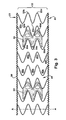
- an innerspring generally referenced at 10, has a plurality of springs or coils 20 (herein referred to alternatively as “coils” or “springs”, although the disclosure and invention is not limited to any one particular type or form of spring or coil or other spring or reflexive device).
- the coils 20 are arranged in an array, such as an orthogonal array of columns and rows, and interconnected by lacing wires 30 which in one form or helical wires which are laced about turns of adjacent coils and typically run transverse across a width of the innerspring, but which can be run in other directions.
- the lacing wires can be located at either or both ends of the coils 20, as shown for example in FIG. 3 .
- Coil ends 23 and 24 are formed at opposite axial ends of the coil body 22 and aligned in the opposing (upper and lower) planes of the innerspring as described.
- the coil ends 23 and 24 are aligned in planes which define support surfaces of the innerspring 10.
- the coils 20 are shown as helical type coils, wherein each coil has a helical and cylindrical form coil body formed by multiple helical turns of wire about a generally linear coil axis A.
- the generally cylindrical coil body is defined by the outer radial extent of each of the turns of the wire helix.
- the coil bodies 22 may include for example five turns 22a, 22b, 22c, 22d and 22e, each of which has an outermost point from the coil axis A.
- Each of the five turns is generally laterally aligned with the corresponding turns of adjacent coils as shown.
- the repeating helical pattern of the rows of coils thus forms a repeating pattern of wave-form gaps or openings between the coils, generally indicated at 40.
- foam dampening inserts 50 are located to varying degrees within the gaps or openings 40.
- the foam dampening inserts 50 can be installed in the innerspring in transverse or longitudinal directions, or both, as illustrated by the Figures.
- the lacing wires 30 are shown oriented in a transverse direction in the innerspring 40 as the conventional arrangement, although longitudinal orientation of the lacing wires 30 is also possible. Accordingly, the foam dampening inserts 50 may be oriented transverse (perpendicular) to or parallel with the lacing wires 30.
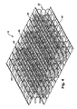
- FIGS. 4-8 illustrate foam dampening inserts 50 installed in an innerspring 10 in an orientation parallel to the lacing wires 30, in a transverse width-wise direction of the innerspring 10.
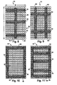
- FIGS. 9-12 illustrate foam dampening inserts 50 installed in innersprings 10 in both longitudinal and transverse directions with respect to the longitudinal and transverse directions of the innersprings.
- the foam dampening inserts 50 have a cross-sectional configuration which includes segments which fit between the coils, in the gaps or openings 40 formed between the spaced-apart coils, and segments or parts which fit within the coil bodies of adjacent coils.
- the turns 22 of the coil are generally laterally aligned and together form a wave-form or serpentine spaces or openings 40 between each coil and between the rows and columns of coils.
- the boundaries of the spaces or openings 40 are defined by the outer diameter form of the adjacent coils 20.
- the openings 40 have different zones or areas or regions as indicated, 40a, 40b, 40c, 40d, 40e and 40f, (also referred to herein in the alternative as "opening regions” or "spaces") defined by the helical turns of the opposing coils 20.
- the opening regions 40a-40f extend into the respective coil bodies.
- the foam dampening inserts 50 are configured to fit within the openings 40 and within at least two or more of the opening regions 40a-40f in order to engage with and maintain alignment and registration with the coils of the innerspring.
- the number of openings 40 will vary according to the number of helical turns in the coil body.
- One representative cross-sectional form of a foam dampening insert 50 of the disclosure includes a central core 50i and segments 50a, 50b, 50c, 50d and 50e as labeled, which extend from the central core 50i in generally opposing and first and second directions, and fit respectively within opening regions 40a, 40b, 40c, 40d and 40e of an opening 40 between two adjacent coils or rows of adjacent coils.
- the different segments 50a-50e of the foam dampening insert 50 are preferably located at different or unique elevations relative to the central core 50i and respective the coil axis A, and because they project laterally from central core 50i of the insert into the adjacent coil bodies and intersect the coil axes A, the foam dampening insert 50 is thereby held securely in place by engagement with the coils for permanent installation and spring dampening performance.
- the exact form of the segments 50a-50e of the foam dampening insert 50 may vary, so long as they effectively extend into the coil bodies, i.e., into the respective opening regions 40a-40e.
- the described engagement of the foam dampening inserts 50 with the openings 40 is essentially the same in both orientations in a conventional innerspring wherein the coils equally spaced omni-directionally.
- the invention however is also applicable to innersprings wherein the coils may be differently spaced, for example in the transverse direction, than in the longitudinal direction, in which case accordingly sized foam dampening inserts could be made per the different required dimensions.
- the foam dampening insert 50 may be configured with any number of segments, including fewer than or greater than five, as shown. In the case where there are a greater number of openings 40 than segments 50a-n of the foam dampening insert 50, the foam dampening insert 50 can be located equidistant, or closer to one or the other side of the innerspring, as defined by the planes in which the coil ends 23, 24 are located.
- a further design aspect and feature of the foam dampening inserts 50 of the disclosure is the lateral extension of the segments 50a-50e from the central core 50i which resides principally between the adjacent coils.
- This lateral extension allows the segments 50a-50e to act as leaf spring members in concert with the compression and recoil of the helical turns of the coil bodies.
- the foam dampening insert 50 is correspondingly compressed in at least two principle modes, one by compression of the insert 50 in its substantial entirety, i.e., along an axis generally parallel to the coils axes A and compression of the central core 50i, and by vertical deflection of the laterally extending segments 50a-50e induced by contact with a corresponding turn or segment of the engaged coil.
- the foam dampening insert 50 has a spring rate which may be different than that of the coils, such as a spring rate which is less than that of the coils or less than an aggregate spring rate of the innerspring 10, the foam dampening insert 50 thus acts as a dampener to reduce the overall spring rate of the innerspring and mattress, in the region or zone where the insert 50 is installed in the innerspring 10.
- the zone or overall or average spring rate of the innerspring or mattress can be designed or tuned by combinations of the known spring rates of the coils and of the inserts 50.
- the spring rate of the wire form helical coils is determined by the coil design, including such design factors as height, diameter, number of turns in the helix and angles or pitch between the turns.
- the spring rate of the innerspring is also affected by the number or density of coils, their relative arrangement and manner of interconnection, such as lacing wires.
- the spring rate and/or dampening effect of the foam dampening inserts 50 is determined and can be adjusted by such factors as the type of foam material and additives used, density, method of formation (e.g., injection molded or extruded), and design configuration such as the cross-section including size and shape of the central core 50i and the number, size and shape and orientation of the segments 50a-50e.For example, openings or voids may be formed in the central core 50i in order to reduce material and accordingly alter the spring rate and dampening effect.
- the shape or shapes of the segments 50a-50e may be made to fit tightly or loosely with the corresponding regions 40a-40e, and may be tapered or contoured in accordance with the coil helix.
- the cross-sectional thickness of one or more of the segments 50a-50e is less than or substantially less than a cross-sectional thickness of the central core 50i.
- the cross-sectional configurations may differ among the various segments 50a-50e, such as for example some being thicker than others, some having a different shape or profile, and some being tapered to a lesser or greater extent than others at points distant from the central core 50i.
- One or more openings or voids 50o may be formed in the foam dampening inserts 50, such as for example in the central core 50i or in any of the segments or regions.
- the size, shape and location of openings or voids 50o are further design parameters which can be set to establish the spring rate or dampening effect of the insert 50 in combination with an innerspring.
- These and other shapes, configurations and structures can be made as foam structures which are molded or extruded of suitable types of polyurethane foams and alloys thereof.
- a preferred method of manufacture is by extrusion through a die which defines the described cross-sectional configuration, in any lengths for widthwise or lengthwise installation dimensioned with innersprings.
- the foam dampening inserts 50 are formed with an exterior skin
- the foam dampening inserts 50 may be arranged in any number, any length and any orientation, or combinations thereof, with an innerspring 10.
- the foam dampening inserts 50 run perpendicular to the transversely extending lacing wires 30.
- the form dampening inserts are parallel with the transverse lacing wires 30.
- FIGS. 9-12 illustrate various combinations of longitudinal and transverse arrangements of different lengths of foam dampening inserts 50 within innersprings 10.
- Each section or piece of the inserts 50 can be closely abutted with an intersecting section or piece, or a space left therebetween.
- the number, size and location of the foam dampening inserts 50 can also create or define zones or regions of the innerspring which have different support characteristics from other zones or regions. These can accordingly be placed or designed for particular mattress application, such as creating increased support and/or pressure-reducing areas or zones in cooperation with overlying layers of material such as foam padding layers, woven and non-woven material layers and upholstery including padded upholstery.
- FIG. 7 illustrates a foam dampened innerspring of the disclosure in combination with one or more internal layers of material or materials 60 which constitute padding or compressible support layers, and an exterior upholstery layer 70 which may further include additional or integral material 72 as additional padding material for a sleep or support surface S.
- Internal material layers 60 may include foam, natural and/or synthetic materials such as cotton, wool, feathers, and/or woven or non-woven fibers.
Description
- The invention is in the general field of reflexive support systems, springs and spring systems, including support systems for humans such as seating and bedding.
- Different types of springs and spring systems are commonly used as the reflexive core of seating and support products such as chairs and mattresses. A common spring system which is used in mattresses and some upholstered furniture is the so-called "innerspring" which can be in one form a plurality of similarly or identically formed springs which are interconnected in an array or matrix. An innerspring provides a distributed generally homogeneous reflexive support system to give underlying support to an expanse such as the sleep surface of a mattress. The uniform spring rate across the expanse results from the common configuration of each of the interconnected springs. Attempts to alter the spring rate and feel of an entire innerspring or support areas of an innerspring involve the use of different types and amounts of materials such as foam, textiles and natural fibers as overlays on the innerspring. While the use of such materials does alter the feel and performance of the support system, it does not of course alter the spring rate of the underlying or internal innerspring.
- Innersprings which are made of formed steel wire are manufactured by wire forming machinery which forms the individual springs or coils, and then connects them together by smaller lacing wires or other fasteners. Once the machines are set up to make a particular spring or coil design and interconnection, large runs are made and it is difficult to change the form of the springs and innerspring. Therefore, with current innerspring production technology, it is not practical to produce a single innerspring which has variable or non-homogeneous spring rates and support characteristics in different areas of the innerspring.
EP 0796580 A1 describes a spring core for a cushion, wherein the core comprises a large number of springs which are inserted in the central foam body, on which there are covering layers. - The invention provides a mattress with a foam dampened innerspring as set out in the accompanying claims.
- This and other aspects of the disclosure and invention are described in further detail herein with reference to the accompanying drawing Figures.
- In the Drawings which constitute a part of the disclosure:
-
FIG. 1 is a perspective view of an innerspring of the disclosure with dampening inserts of the disclosure; -
FIG. 2 is a plan view of the innerspring ofFIG. 1 ; -
FIG. 3 is a partial side elevation of the innerspring ofFIG. 1 ; -
FIG. 4 is a perspective view of an alternate embodiment of an innerspring of the disclosure and dampening inserts of the disclosure; -
FIG. 5 is a plan view of the innerspring ofFIG. 4 ; -
FIG. 6 is a partial side elevation of the innerspring ofFIG. 4 ; -
FIG. 7 is a partial side elevation of a foam dampened innerspring of the disclosure, and -
FIGS. 8-12 are plan views of various alternate and representative embodiments of foam dampened innersprings of the disclosure. - As shown in the drawings Figures, an innerspring, generally referenced at 10, has a plurality of springs or coils 20 (herein referred to alternatively as "coils" or "springs", although the disclosure and invention is not limited to any one particular type or form of spring or coil or other spring or reflexive device). The
coils 20 are arranged in an array, such as an orthogonal array of columns and rows, and interconnected by lacingwires 30 which in one form or helical wires which are laced about turns of adjacent coils and typically run transverse across a width of the innerspring, but which can be run in other directions. The lacing wires can be located at either or both ends of thecoils 20, as shown for example inFIG. 3 .Coil ends coil body 22 and aligned in the opposing (upper and lower) planes of the innerspring as described. Thecoil ends innerspring 10. In many innersprings of this type, there is open space between theadjacent coil bodies 22, necessary to allow flexure, compression and deflection of the coils and relative movement without inter-coil contact. - The
coils 20 are shown as helical type coils, wherein each coil has a helical and cylindrical form coil body formed by multiple helical turns of wire about a generally linear coil axis A. The generally cylindrical coil body is defined by the outer radial extent of each of the turns of the wire helix. For each coil, the areas which are within the turns of the wire helix which form the coil body are within the coil body. As illustrated inFIGS. 3 and6 , thecoil bodies 22 may include for example fiveturns foam dampening inserts 50 are located to varying degrees within the gaps oropenings 40. - In a conventional innerspring the openings between the coils are generally uniform in each lateral direction, i.e., the longitudinal and transverse directions of the innerspring. Therefore, the
foam dampening inserts 50 can be installed in the innerspring in transverse or longitudinal directions, or both, as illustrated by the Figures. In the Figures, thelacing wires 30 are shown oriented in a transverse direction in theinnerspring 40 as the conventional arrangement, although longitudinal orientation of thelacing wires 30 is also possible. Accordingly, thefoam dampening inserts 50 may be oriented transverse (perpendicular) to or parallel with thelacing wires 30. For example,FIGS. 1-3 illustratefoam dampening inserts 50 installed in aninnerspring 10 in an orientation transverse to thelacing wires 30, or in other words in a longitudinal direction of theinnerspring 10.FIGS. 4-8 illustratefoam dampening inserts 50 installed in aninnerspring 10 in an orientation parallel to thelacing wires 30, in a transverse width-wise direction of theinnerspring 10. AndFIGS. 9-12 illustratefoam dampening inserts 50 installed ininnersprings 10 in both longitudinal and transverse directions with respect to the longitudinal and transverse directions of the innersprings. - The
foam dampening inserts 50 have a cross-sectional configuration which includes segments which fit between the coils, in the gaps oropenings 40 formed between the spaced-apart coils, and segments or parts which fit within the coil bodies of adjacent coils. As shown for example inFIGS. 3 ,6 and7 , with thecoils 20 in generally helical form, theturns 22 of the coil are generally laterally aligned and together form a wave-form or serpentine spaces oropenings 40 between each coil and between the rows and columns of coils. In other words, the boundaries of the spaces oropenings 40 are defined by the outer diameter form of theadjacent coils 20. Theopenings 40 have different zones or areas or regions as indicated, 40a, 40b, 40c, 40d, 40e and 40f, (also referred to herein in the alternative as "opening regions" or "spaces") defined by the helical turns of theopposing coils 20. Theopening regions 40a-40f extend into the respective coil bodies. Thefoam dampening inserts 50 are configured to fit within theopenings 40 and within at least two or more of theopening regions 40a-40f in order to engage with and maintain alignment and registration with the coils of the innerspring. The number ofopenings 40 will vary according to the number of helical turns in the coil body. - One representative cross-sectional form of a foam dampening insert 50 of the disclosure includes a central core 50i and
segments opening regions different segments 50a-50e of thefoam dampening insert 50 are preferably located at different or unique elevations relative to the central core 50i and respective the coil axis A, and because they project laterally from central core 50i of the insert into the adjacent coil bodies and intersect the coil axes A, thefoam dampening insert 50 is thereby held securely in place by engagement with the coils for permanent installation and spring dampening performance. As further shown inFIG. 3 , the exact form of thesegments 50a-50e of thefoam dampening insert 50 may vary, so long as they effectively extend into the coil bodies, i.e., into the respectiveopening regions 40a-40e. As noted, because theopenings 40 exist between the coils in both the transverse and longitudinal directions of the innerspring, the described engagement of thefoam dampening inserts 50 with theopenings 40 is essentially the same in both orientations in a conventional innerspring wherein the coils equally spaced omni-directionally. The invention however is also applicable to innersprings wherein the coils may be differently spaced, for example in the transverse direction, than in the longitudinal direction, in which case accordingly sized foam dampening inserts could be made per the different required dimensions. - Also, because the number of
openings 40 may be greater than the number ofsegments 50a-n of thefoam dampening insert 50, thefoam dampening insert 50 may be configured with any number of segments, including fewer than or greater than five, as shown. In the case where there are a greater number ofopenings 40 thansegments 50a-n of the foam dampening insert 50, thefoam dampening insert 50 can be located equidistant, or closer to one or the other side of the innerspring, as defined by the planes in which the coil ends 23, 24 are located. - A further design aspect and feature of the
foam dampening inserts 50 of the disclosure is the lateral extension of thesegments 50a-50e from the central core 50i which resides principally between the adjacent coils. This lateral extension allows thesegments 50a-50e to act as leaf spring members in concert with the compression and recoil of the helical turns of the coil bodies. As the coils are compressed under a normal load, thefoam dampening insert 50 is correspondingly compressed in at least two principle modes, one by compression of theinsert 50 in its substantial entirety, i.e., along an axis generally parallel to the coils axes A and compression of the central core 50i, and by vertical deflection of the laterally extendingsegments 50a-50e induced by contact with a corresponding turn or segment of the engaged coil. Because the foam dampening insert has a spring rate which may be different than that of the coils, such as a spring rate which is less than that of the coils or less than an aggregate spring rate of theinnerspring 10, the foam dampening insert 50 thus acts as a dampener to reduce the overall spring rate of the innerspring and mattress, in the region or zone where theinsert 50 is installed in theinnerspring 10. In this regard the zone or overall or average spring rate of the innerspring or mattress can be designed or tuned by combinations of the known spring rates of the coils and of theinserts 50. As known in the wire-forming arts, the spring rate of the wire form helical coils is determined by the coil design, including such design factors as height, diameter, number of turns in the helix and angles or pitch between the turns. The spring rate of the innerspring is also affected by the number or density of coils, their relative arrangement and manner of interconnection, such as lacing wires. - The spring rate and/or dampening effect of the
foam dampening inserts 50 is determined and can be adjusted by such factors as the type of foam material and additives used, density, method of formation (e.g., injection molded or extruded), and design configuration such as the cross-section including size and shape of the central core 50i and the number, size and shape and orientation of thesegments 50a-50e.For example, openings or voids may be formed in the central core 50i in order to reduce material and accordingly alter the spring rate and dampening effect. The shape or shapes of thesegments 50a-50e may be made to fit tightly or loosely with the correspondingregions 40a-40e, and may be tapered or contoured in accordance with the coil helix. In one design aspect, the cross-sectional thickness of one or more of thesegments 50a-50e is less than or substantially less than a cross-sectional thickness of the central core 50i. Also, the cross-sectional configurations may differ among thevarious segments 50a-50e, such as for example some being thicker than others, some having a different shape or profile, and some being tapered to a lesser or greater extent than others at points distant from the central core 50i. One or more openings or voids 50o may be formed in thefoam dampening inserts 50, such as for example in the central core 50i or in any of the segments or regions. The size, shape and location of openings or voids 50o are further design parameters which can be set to establish the spring rate or dampening effect of theinsert 50 in combination with an innerspring. These and other shapes, configurations and structures can be made as foam structures which are molded or extruded of suitable types of polyurethane foams and alloys thereof. A preferred method of manufacture is by extrusion through a die which defines the described cross-sectional configuration, in any lengths for widthwise or lengthwise installation dimensioned with innersprings. When made as extrusions, thefoam dampening inserts 50 are formed with an exterior skin - As shown in the Figures and mentioned, the
foam dampening inserts 50 may be arranged in any number, any length and any orientation, or combinations thereof, with an innerspring 10. In a longitudinal orientation shown inFIGS. 1 and2 , thefoam dampening inserts 50 run perpendicular to the transversely extendinglacing wires 30. In the width-wise transverse orientation shown inFIGS. 4-8 , the form dampening inserts are parallel with thetransverse lacing wires 30.FIGS. 9-12 illustrate various combinations of longitudinal and transverse arrangements of different lengths offoam dampening inserts 50 withininnersprings 10. Each section or piece of theinserts 50 can be closely abutted with an intersecting section or piece, or a space left therebetween. The number, size and location of thefoam dampening inserts 50 can also create or define zones or regions of the innerspring which have different support characteristics from other zones or regions. These can accordingly be placed or designed for particular mattress application, such as creating increased support and/or pressure-reducing areas or zones in cooperation with overlying layers of material such as foam padding layers, woven and non-woven material layers and upholstery including padded upholstery. -
FIG. 7 illustrates a foam dampened innerspring of the disclosure in combination with one or more internal layers of material ormaterials 60 which constitute padding or compressible support layers, and anexterior upholstery layer 70 which may further include additional orintegral material 72 as additional padding material for a sleep or support surface S. In this manner a mattress may be configured with one or two support or sleep surfaces S. Internal material layers 60 may include foam, natural and/or synthetic materials such as cotton, wool, feathers, and/or woven or non-woven fibers.
Claims (10)
- A mattress with a foam dampened innerspring, comprising: an innerspring (10) having a plurality of coils (20) interconnected in an array of columns and rows, the columns of coils being generally equally spaced apart, and the rows of coils being generally equally spaced apart, each coil having a generally helical wire form body with openings between helical turns of wire of the helical wire form body; at least one foam dampening insert (50) located in the innerspring between coils of the array, the at least one foam dampening insert having a central core which fits in a space (40) between a row or column of coils of the array, and at least two segments which extend laterally from the central core and into one or more openings between the helical turns of wire of the helical wire form bodies of at least two adjacent coils of the array, and padding (72) and upholstery (70) material positioned over a support surface of the innerspring to form a mattress, wherein the at least one foam dampening insert has at least three segments (50a, 50b, 50c) which extend laterally from the central core and which are configured to fit within openings in the helical turns of the helical wire form bodies of adjacent coils, two (50a, 50c) of the at least three segments extending from the central core in a first direction and at two different elevations, and one (50b) of the at least three segments extending from the central core in a second direction at a third elevation which is unique from the two different elevations of the other two segments.
- The mattress of claim 1, wherein each of the segments of the foam dampening insert (50) are configured to fit in an opening in the helical wire form body of a coil and extend through a substantial cross-section of die coil so that the segments are intersected by a longitudinal axis of the coil into which the segment extends.
- The mattress of any one of claims 1 to 2, wherein each of the segments of the foam dampening insert (50) have a cross-sectional thickness in an area proximal to the central core which is greater than a cross-sectional thickness in an area distal from the central core.
- The mattress of any one of the preceding claims, wherein the foam dampening inserts (50) have a cross-sectional configuration in the general configuration of the letter W.
- The mattress of any one of the preceding claims, wherein the foam dampening insert (50) is positioned within the innerspring closer to a bottom of the mattress than to a support surface of the mattress.
- The mattress of any one of the preceding claims, wherein the foam dampening insert (50) is positioned within the innerspring closer to a support surface of the mattress than to a bottom of the mattress.
- The mattress of any one of the preceding claims, comprising a plurality of foam dampening inserts (50) which at least partially define different zones of the mattress.
- The mattress of any one of the preceding claims, comprising a plurality of foam dampening inserts (50) at least some of which are located proximate to a perimeter of the innerspring and mattress.
- The mattress of any one of the preceding claims, comprising a plurality of foam dampening inserts (50), at least two of which are perpendicularly oriented within the innerspring.
- The mattress of any one of the preceding claims, comprising at least two foam dampening inserts (50) each having a unique cross-sectional configuration.
Applications Claiming Priority (2)
| Application Number | Priority Date | Filing Date | Title |
|---|---|---|---|
| US12/016,374 US7636971B2 (en) | 2008-01-18 | 2008-01-18 | Innerspring dampening inserts |
| PCT/US2009/031197 WO2009091945A1 (en) | 2008-01-18 | 2009-01-16 | Innerspring dampening inserts |
Publications (3)
| Publication Number | Publication Date |
|---|---|
| EP2296509A1 EP2296509A1 (en) | 2011-03-23 |
| EP2296509A4 EP2296509A4 (en) | 2011-08-17 |
| EP2296509B1 true EP2296509B1 (en) | 2012-10-24 |
Family
ID=40875249
Family Applications (1)
| Application Number | Title | Priority Date | Filing Date |
|---|---|---|---|
| EP09702497A Not-in-force EP2296509B1 (en) | 2008-01-18 | 2009-01-16 | Innerspring dampening inserts |
Country Status (9)
| Country | Link |
|---|---|
| US (1) | US7636971B2 (en) |
| EP (1) | EP2296509B1 (en) |
| KR (1) | KR101559748B1 (en) |
| CN (1) | CN101977535A (en) |
| BR (1) | BRPI0906744A2 (en) |
| CA (1) | CA2712457A1 (en) |
| MX (1) | MX2010007835A (en) |
| NZ (1) | NZ586847A (en) |
| WO (1) | WO2009091945A1 (en) |
Families Citing this family (21)
| Publication number | Priority date | Publication date | Assignee | Title |
|---|---|---|---|---|
| WO2008088740A1 (en) * | 2007-01-18 | 2008-07-24 | Nomaco, Inc. | Method for manufacturing enhanced foam thermoplastic products |
| US20100325806A1 (en) * | 2007-10-09 | 2010-12-30 | Sealy Technology, Llc | Pressure dispersion support systems |
| US7845035B2 (en) * | 2007-10-09 | 2010-12-07 | Sealy Technology Llc | Pressure dispersion support systems |
| US7636971B2 (en) * | 2008-01-18 | 2009-12-29 | Sealy Technology Llc | Innerspring dampening inserts |
| US8230538B2 (en) * | 2008-01-18 | 2012-07-31 | Sealy Technology Llc | Mattress innerspring inserts and supports |
| US7805790B2 (en) * | 2008-01-18 | 2010-10-05 | Sealy Technology Llc | Foam springs and innerspring combinations for mattresses |
| US8813286B2 (en) * | 2010-06-10 | 2014-08-26 | Indratech Llc | Tunable spring mattress and method of making same |
| US9392877B2 (en) | 2010-06-10 | 2016-07-19 | Indratech Llc | Tunable spring mattress and method of making same |
| US20120304392A1 (en) * | 2011-05-31 | 2012-12-06 | Khambete Surendra S | Mattress system |
| MX2011010467A (en) * | 2011-10-04 | 2013-04-22 | Leon Blanga Cohen | Coated springs and mattress manufactured therewith. |
| US8931531B2 (en) * | 2012-05-18 | 2015-01-13 | The Goodyear Tire & Rubber Company | System for non-pneumatic support of a vehicle |
| US11076705B2 (en) | 2014-05-30 | 2021-08-03 | Sealy Technology, Llc | Spring core with integrated cushioning layer |
| WO2016122453A1 (en) * | 2015-01-27 | 2016-08-04 | Sealy Technology, Llc | Coiled spring with variable resistance and mattresses including the same |
| US11033114B2 (en) | 2015-12-17 | 2021-06-15 | Sealy Technology, Llc | Coil-in-coil spring with variable loading response and mattresses including the same |
| JP6794457B2 (en) | 2016-01-21 | 2020-12-02 | シーリー テクノロジー リミテッド ライアビリティ カンパニー | A coil-in-coil spring that exhibits a non-linear load response, and a mattress with that spring |
| EP3554315A4 (en) | 2016-12-15 | 2020-06-03 | Sealy Technology, LLC | Open coil spring assemblies |
| AU2016434431B2 (en) | 2016-12-29 | 2023-02-02 | Sealy Technology, Llc | Mattress assembly with a mattress topper that includes pocketed coil springs and methods of producing the same |
| FR3066087B1 (en) * | 2017-05-12 | 2019-07-05 | Tournadre Sa Standard Gum | ADJUSTABLE STIFFENER ELEMENT FOR SLEEP OR SEAT FURNITURE |
| FR3066088B1 (en) | 2017-05-12 | 2019-07-05 | Tournadre Sa Standard Gum | STIFF ADJUSTER DEVICE |
| CN111114225B (en) * | 2019-12-24 | 2021-08-13 | 上海采埃孚伦福德底盘技术有限公司 | Vehicle suspension control arm based on array type shock absorber and parameter calculation method |
| KR102261891B1 (en) * | 2020-11-16 | 2021-06-08 | 주식회사 금성침대 | Bed mattress with reinforcing performance |
Family Cites Families (26)
| Publication number | Priority date | Publication date | Assignee | Title |
|---|---|---|---|---|
| US2446775A (en) * | 1944-01-12 | 1948-08-10 | Marsack Patents Corp | Innerspring mattress construction |
| US2585415A (en) * | 1948-03-31 | 1952-02-12 | Toms William Alfred | Reversible cushion device |
| US2826769A (en) * | 1956-01-31 | 1958-03-18 | Eclipse Sleep Products Inc | Border stabilizer |
| US2940089A (en) * | 1956-12-24 | 1960-06-14 | Englander Co Inc | Mattress structure |
| US3010122A (en) * | 1956-12-24 | 1961-11-28 | Englander Co Inc | Resilient pad structure |
| US3099021A (en) * | 1957-05-28 | 1963-07-30 | Englander Co Inc | Foam mattress |
| US3618146A (en) * | 1969-04-24 | 1971-11-09 | Us Bedding Co The | Border stabilizer |
| US3822426A (en) * | 1972-11-03 | 1974-07-09 | Sealy | Mattress topper pad and border stabilizer |
| US3981033A (en) * | 1974-10-12 | 1976-09-21 | France Bed Co. Ltd. | Mattress |
| US5239715A (en) * | 1992-02-11 | 1993-08-31 | The Ohio Mattress Company Licensing And Components Group | Border stabilizing and reinforcing member for use in mattresses, cushions and the like |
| US5467488A (en) * | 1992-02-11 | 1995-11-21 | The Ohio Mattress Co. Licensing & Components Group | Border stabilizing member and method for making mattresses, cushions and the like using the same |
| US5210890A (en) * | 1992-09-21 | 1993-05-18 | Tualatin Sleep Products | Mattress foundation with springs and foam elements |
| CA2090643A1 (en) * | 1993-03-01 | 1994-09-02 | Paul W. Reinhardt | Contourable pocket foam mattress and method of manufacture |
| US5469590A (en) * | 1994-03-04 | 1995-11-28 | The Spring Air Company | Mattress with compressible support members |
| BE1009544A3 (en) * | 1995-08-16 | 1997-05-06 | Imhold Naamloze Vennootschap | Composite elastic springy element and springy SUPPORT ELEMENT WITH SUCH SUSPENSION ELEMENTS. |
| ATE199633T1 (en) * | 1996-02-02 | 2001-03-15 | Meinrad Helbling Ag Bootswerft | SPRING CORE FOR UPHOLSTERY |
| US5787532A (en) * | 1996-10-04 | 1998-08-04 | The Ohio Mattress Company Licensing And Components Group | Internal mattress wall structures interlockingly engageable with mattress innerspring assemblies |
| US5724686A (en) * | 1997-02-25 | 1998-03-10 | Eastern Sleep Products, Inc. | Cushion or mattress border support |
| US6023803A (en) * | 1997-11-07 | 2000-02-15 | Ohio Mattress Company Licensing And Components Group | Mattress with high ILD firm topper |
| US6128798A (en) * | 1998-09-04 | 2000-10-10 | Sealy Technology Llc | Cavitated pad and innerspring assembly combination having springs with free terminal convolutions |
| JP2004016341A (en) * | 2002-06-13 | 2004-01-22 | France Bed Co Ltd | Mattress device |
| US7082635B2 (en) * | 2003-03-28 | 2006-08-01 | Sealy Technology Llc | Unitized thermoplastic foam structures |
| KR200340156Y1 (en) * | 2003-10-27 | 2004-01-31 | 주식회사 에이스침대 | Structure of reinforceing the spring assembly using in matress |
| US7845036B2 (en) * | 2007-07-09 | 2010-12-07 | Hickory Springs Manufacturing Company | Edge support for mattress assembly and method for making and using the same |
| US7636971B2 (en) * | 2008-01-18 | 2009-12-29 | Sealy Technology Llc | Innerspring dampening inserts |
| US7805790B2 (en) * | 2008-01-18 | 2010-10-05 | Sealy Technology Llc | Foam springs and innerspring combinations for mattresses |
-
2008
- 2008-01-18 US US12/016,374 patent/US7636971B2/en active Active
-
2009
- 2009-01-16 BR BRPI0906744-2A patent/BRPI0906744A2/en not_active IP Right Cessation
- 2009-01-16 WO PCT/US2009/031197 patent/WO2009091945A1/en active Application Filing
- 2009-01-16 NZ NZ586847A patent/NZ586847A/en unknown
- 2009-01-16 MX MX2010007835A patent/MX2010007835A/en not_active Application Discontinuation
- 2009-01-16 KR KR1020107018254A patent/KR101559748B1/en active IP Right Grant
- 2009-01-16 CA CA2712457A patent/CA2712457A1/en not_active Abandoned
- 2009-01-16 EP EP09702497A patent/EP2296509B1/en not_active Not-in-force
- 2009-01-16 CN CN2009801096314A patent/CN101977535A/en active Pending
Also Published As
| Publication number | Publication date |
|---|---|
| BRPI0906744A2 (en) | 2015-07-07 |
| CN101977535A (en) | 2011-02-16 |
| US20090183315A1 (en) | 2009-07-23 |
| AU2009206026A1 (en) | 2009-07-23 |
| NZ586847A (en) | 2011-10-28 |
| KR101559748B1 (en) | 2015-10-13 |
| MX2010007835A (en) | 2010-09-30 |
| EP2296509A1 (en) | 2011-03-23 |
| WO2009091945A1 (en) | 2009-07-23 |
| CA2712457A1 (en) | 2009-01-18 |
| KR20100129276A (en) | 2010-12-08 |
| EP2296509A4 (en) | 2011-08-17 |
| US7636971B2 (en) | 2009-12-29 |
Similar Documents
| Publication | Publication Date | Title |
|---|---|---|
| EP2296509B1 (en) | Innerspring dampening inserts | |
| CA2820219C (en) | Mattress innerspring inserts and supports | |
| US20120000018A1 (en) | Posture channel supports | |
| US5469590A (en) | Mattress with compressible support members | |
| US20090193591A1 (en) | Variable coil density anisotropic innersprings | |
| EP3937731B1 (en) | Comfort layer having spacer pocketed springs | |
| AU2009206026B2 (en) | Innerspring dampening inserts | |
| US5649332A (en) | Posturized continuous mattress spring core | |
| EP3400844A1 (en) | Spring core with pocketed coil and foam springs | |
| EP3937729A1 (en) | Comfort layer having pocketed springs of different heights | |
| EP3937730A1 (en) | Comfort layer having repeating pattern of pocketed mini coil springs of different heights | |
| AU746738B2 (en) | Spring mattress | |
| US20210337980A1 (en) | Mattress | |
| US20120047657A1 (en) | Spring Assembly Having Continuous Bands of Springs |
Legal Events
| Date | Code | Title | Description |
|---|---|---|---|
| PUAI | Public reference made under article 153(3) epc to a published international application that has entered the european phase |
Free format text: ORIGINAL CODE: 0009012 |
|
| 17P | Request for examination filed |
Effective date: 20101214 |
|
| AK | Designated contracting states |
Kind code of ref document: A1 Designated state(s): AT BE BG CH CY CZ DE DK EE ES FI FR GB GR HR HU IE IS IT LI LT LU LV MC MK MT NL NO PL PT RO SE SI SK TR |
|
| AX | Request for extension of the european patent |
Extension state: AL BA RS |
|
| DAX | Request for extension of the european patent (deleted) | ||
| A4 | Supplementary search report drawn up and despatched |
Effective date: 20110719 |
|
| RIC1 | Information provided on ipc code assigned before grant |
Ipc: A47C 23/04 20060101AFI20110713BHEP |
|
| GRAP | Despatch of communication of intention to grant a patent |
Free format text: ORIGINAL CODE: EPIDOSNIGR1 |
|
| GRAS | Grant fee paid |
Free format text: ORIGINAL CODE: EPIDOSNIGR3 |
|
| GRAA | (expected) grant |
Free format text: ORIGINAL CODE: 0009210 |
|
| AK | Designated contracting states |
Kind code of ref document: B1 Designated state(s): AT BE BG CH CY CZ DE DK EE ES FI FR GB GR HR HU IE IS IT LI LT LU LV MC MK MT NL NO PL PT RO SE SI SK TR |
|
| REG | Reference to a national code |
Ref country code: GB Ref legal event code: FG4D |
|
| REG | Reference to a national code |
Ref country code: CH Ref legal event code: EP |
|
| REG | Reference to a national code |
Ref country code: AT Ref legal event code: REF Ref document number: 580432 Country of ref document: AT Kind code of ref document: T Effective date: 20121115 |
|
| REG | Reference to a national code |
Ref country code: IE Ref legal event code: FG4D |
|
| REG | Reference to a national code |
Ref country code: DE Ref legal event code: R096 Ref document number: 602009010628 Country of ref document: DE Effective date: 20121227 |
|
| REG | Reference to a national code |
Ref country code: AT Ref legal event code: MK05 Ref document number: 580432 Country of ref document: AT Kind code of ref document: T Effective date: 20121024 |
|
| REG | Reference to a national code |
Ref country code: NL Ref legal event code: VDEP Effective date: 20121024 |
|
| PG25 | Lapsed in a contracting state [announced via postgrant information from national office to epo] |
Ref country code: IS Free format text: LAPSE BECAUSE OF FAILURE TO SUBMIT A TRANSLATION OF THE DESCRIPTION OR TO PAY THE FEE WITHIN THE PRESCRIBED TIME-LIMIT Effective date: 20130224 Ref country code: NL Free format text: LAPSE BECAUSE OF FAILURE TO SUBMIT A TRANSLATION OF THE DESCRIPTION OR TO PAY THE FEE WITHIN THE PRESCRIBED TIME-LIMIT Effective date: 20121024 Ref country code: HR Free format text: LAPSE BECAUSE OF FAILURE TO SUBMIT A TRANSLATION OF THE DESCRIPTION OR TO PAY THE FEE WITHIN THE PRESCRIBED TIME-LIMIT Effective date: 20121024 Ref country code: ES Free format text: LAPSE BECAUSE OF FAILURE TO SUBMIT A TRANSLATION OF THE DESCRIPTION OR TO PAY THE FEE WITHIN THE PRESCRIBED TIME-LIMIT Effective date: 20130204 Ref country code: SE Free format text: LAPSE BECAUSE OF FAILURE TO SUBMIT A TRANSLATION OF THE DESCRIPTION OR TO PAY THE FEE WITHIN THE PRESCRIBED TIME-LIMIT Effective date: 20121024 Ref country code: NO Free format text: LAPSE BECAUSE OF FAILURE TO SUBMIT A TRANSLATION OF THE DESCRIPTION OR TO PAY THE FEE WITHIN THE PRESCRIBED TIME-LIMIT Effective date: 20130124 Ref country code: FI Free format text: LAPSE BECAUSE OF FAILURE TO SUBMIT A TRANSLATION OF THE DESCRIPTION OR TO PAY THE FEE WITHIN THE PRESCRIBED TIME-LIMIT Effective date: 20121024 |
|
| PGFP | Annual fee paid to national office [announced via postgrant information from national office to epo] |
Ref country code: GB Payment date: 20130116 Year of fee payment: 5 Ref country code: FR Payment date: 20130204 Year of fee payment: 5 |
|
| PG25 | Lapsed in a contracting state [announced via postgrant information from national office to epo] |
Ref country code: LV Free format text: LAPSE BECAUSE OF FAILURE TO SUBMIT A TRANSLATION OF THE DESCRIPTION OR TO PAY THE FEE WITHIN THE PRESCRIBED TIME-LIMIT Effective date: 20121024 Ref country code: PT Free format text: LAPSE BECAUSE OF FAILURE TO SUBMIT A TRANSLATION OF THE DESCRIPTION OR TO PAY THE FEE WITHIN THE PRESCRIBED TIME-LIMIT Effective date: 20130225 Ref country code: GR Free format text: LAPSE BECAUSE OF FAILURE TO SUBMIT A TRANSLATION OF THE DESCRIPTION OR TO PAY THE FEE WITHIN THE PRESCRIBED TIME-LIMIT Effective date: 20130125 Ref country code: PL Free format text: LAPSE BECAUSE OF FAILURE TO SUBMIT A TRANSLATION OF THE DESCRIPTION OR TO PAY THE FEE WITHIN THE PRESCRIBED TIME-LIMIT Effective date: 20121024 Ref country code: BE Free format text: LAPSE BECAUSE OF FAILURE TO SUBMIT A TRANSLATION OF THE DESCRIPTION OR TO PAY THE FEE WITHIN THE PRESCRIBED TIME-LIMIT Effective date: 20121024 Ref country code: SI Free format text: LAPSE BECAUSE OF FAILURE TO SUBMIT A TRANSLATION OF THE DESCRIPTION OR TO PAY THE FEE WITHIN THE PRESCRIBED TIME-LIMIT Effective date: 20121024 |
|
| PG25 | Lapsed in a contracting state [announced via postgrant information from national office to epo] |
Ref country code: AT Free format text: LAPSE BECAUSE OF FAILURE TO SUBMIT A TRANSLATION OF THE DESCRIPTION OR TO PAY THE FEE WITHIN THE PRESCRIBED TIME-LIMIT Effective date: 20121024 |
|
| PG25 | Lapsed in a contracting state [announced via postgrant information from national office to epo] |
Ref country code: BG Free format text: LAPSE BECAUSE OF FAILURE TO SUBMIT A TRANSLATION OF THE DESCRIPTION OR TO PAY THE FEE WITHIN THE PRESCRIBED TIME-LIMIT Effective date: 20130124 Ref country code: DK Free format text: LAPSE BECAUSE OF FAILURE TO SUBMIT A TRANSLATION OF THE DESCRIPTION OR TO PAY THE FEE WITHIN THE PRESCRIBED TIME-LIMIT Effective date: 20121024 Ref country code: EE Free format text: LAPSE BECAUSE OF FAILURE TO SUBMIT A TRANSLATION OF THE DESCRIPTION OR TO PAY THE FEE WITHIN THE PRESCRIBED TIME-LIMIT Effective date: 20121024 Ref country code: SK Free format text: LAPSE BECAUSE OF FAILURE TO SUBMIT A TRANSLATION OF THE DESCRIPTION OR TO PAY THE FEE WITHIN THE PRESCRIBED TIME-LIMIT Effective date: 20121024 Ref country code: CZ Free format text: LAPSE BECAUSE OF FAILURE TO SUBMIT A TRANSLATION OF THE DESCRIPTION OR TO PAY THE FEE WITHIN THE PRESCRIBED TIME-LIMIT Effective date: 20121024 |
|
| PG25 | Lapsed in a contracting state [announced via postgrant information from national office to epo] |
Ref country code: MC Free format text: LAPSE BECAUSE OF NON-PAYMENT OF DUE FEES Effective date: 20130131 Ref country code: RO Free format text: LAPSE BECAUSE OF FAILURE TO SUBMIT A TRANSLATION OF THE DESCRIPTION OR TO PAY THE FEE WITHIN THE PRESCRIBED TIME-LIMIT Effective date: 20121024 |
|
| PLBE | No opposition filed within time limit |
Free format text: ORIGINAL CODE: 0009261 |
|
| REG | Reference to a national code |
Ref country code: CH Ref legal event code: PL |
|
| STAA | Information on the status of an ep patent application or granted ep patent |
Free format text: STATUS: NO OPPOSITION FILED WITHIN TIME LIMIT |
|
| 26N | No opposition filed |
Effective date: 20130725 |
|
| REG | Reference to a national code |
Ref country code: IE Ref legal event code: MM4A |
|
| PG25 | Lapsed in a contracting state [announced via postgrant information from national office to epo] |
Ref country code: LI Free format text: LAPSE BECAUSE OF NON-PAYMENT OF DUE FEES Effective date: 20130131 Ref country code: CH Free format text: LAPSE BECAUSE OF NON-PAYMENT OF DUE FEES Effective date: 20130131 Ref country code: DE Free format text: LAPSE BECAUSE OF NON-PAYMENT OF DUE FEES Effective date: 20130801 |
|
| REG | Reference to a national code |
Ref country code: DE Ref legal event code: R119 Ref document number: 602009010628 Country of ref document: DE Effective date: 20130801 |
|
| REG | Reference to a national code |
Ref country code: DE Ref legal event code: R097 Ref document number: 602009010628 Country of ref document: DE Effective date: 20130725 |
|
| PG25 | Lapsed in a contracting state [announced via postgrant information from national office to epo] |
Ref country code: CY Free format text: LAPSE BECAUSE OF FAILURE TO SUBMIT A TRANSLATION OF THE DESCRIPTION OR TO PAY THE FEE WITHIN THE PRESCRIBED TIME-LIMIT Effective date: 20121024 |
|
| PG25 | Lapsed in a contracting state [announced via postgrant information from national office to epo] |
Ref country code: IE Free format text: LAPSE BECAUSE OF NON-PAYMENT OF DUE FEES Effective date: 20130116 |
|
| PG25 | Lapsed in a contracting state [announced via postgrant information from national office to epo] |
Ref country code: LT Free format text: LAPSE BECAUSE OF FAILURE TO SUBMIT A TRANSLATION OF THE DESCRIPTION OR TO PAY THE FEE WITHIN THE PRESCRIBED TIME-LIMIT Effective date: 20121024 Ref country code: MT Free format text: LAPSE BECAUSE OF FAILURE TO SUBMIT A TRANSLATION OF THE DESCRIPTION OR TO PAY THE FEE WITHIN THE PRESCRIBED TIME-LIMIT Effective date: 20121024 |
|
| GBPC | Gb: european patent ceased through non-payment of renewal fee |
Effective date: 20140116 |
|
| REG | Reference to a national code |
Ref country code: FR Ref legal event code: ST Effective date: 20140930 |
|
| PG25 | Lapsed in a contracting state [announced via postgrant information from national office to epo] |
Ref country code: GB Free format text: LAPSE BECAUSE OF NON-PAYMENT OF DUE FEES Effective date: 20140116 Ref country code: FR Free format text: LAPSE BECAUSE OF NON-PAYMENT OF DUE FEES Effective date: 20140131 |
|
| PG25 | Lapsed in a contracting state [announced via postgrant information from national office to epo] |
Ref country code: TR Free format text: LAPSE BECAUSE OF FAILURE TO SUBMIT A TRANSLATION OF THE DESCRIPTION OR TO PAY THE FEE WITHIN THE PRESCRIBED TIME-LIMIT Effective date: 20121024 |
|
| PG25 | Lapsed in a contracting state [announced via postgrant information from national office to epo] |
Ref country code: HU Free format text: LAPSE BECAUSE OF FAILURE TO SUBMIT A TRANSLATION OF THE DESCRIPTION OR TO PAY THE FEE WITHIN THE PRESCRIBED TIME-LIMIT; INVALID AB INITIO Effective date: 20090116 Ref country code: LU Free format text: LAPSE BECAUSE OF NON-PAYMENT OF DUE FEES Effective date: 20130116 Ref country code: MK Free format text: LAPSE BECAUSE OF FAILURE TO SUBMIT A TRANSLATION OF THE DESCRIPTION OR TO PAY THE FEE WITHIN THE PRESCRIBED TIME-LIMIT Effective date: 20121024 |
|
| PG25 | Lapsed in a contracting state [announced via postgrant information from national office to epo] |
Ref country code: IT Free format text: LAPSE BECAUSE OF NON-PAYMENT OF DUE FEES Effective date: 20140116 |
|
| P01 | Opt-out of the competence of the unified patent court (upc) registered |
Effective date: 20230524 |