EP2296352B1 - Mobile terminal - Google Patents
Mobile terminal Download PDFInfo
- Publication number
- EP2296352B1 EP2296352B1 EP10174961.2A EP10174961A EP2296352B1 EP 2296352 B1 EP2296352 B1 EP 2296352B1 EP 10174961 A EP10174961 A EP 10174961A EP 2296352 B1 EP2296352 B1 EP 2296352B1
- Authority
- EP
- European Patent Office
- Prior art keywords
- case
- mobile terminal
- locking
- camera
- terminal body
- Prior art date
- Legal status (The legal status is an assumption and is not a legal conclusion. Google has not performed a legal analysis and makes no representation as to the accuracy of the status listed.)
- Not-in-force
Links
- 238000009434 installation Methods 0.000 claims description 13
- 238000004891 communication Methods 0.000 description 19
- 230000006870 function Effects 0.000 description 11
- 238000000034 method Methods 0.000 description 6
- 238000010295 mobile communication Methods 0.000 description 6
- 230000008569 process Effects 0.000 description 4
- 238000012545 processing Methods 0.000 description 3
- 238000012546 transfer Methods 0.000 description 3
- 238000013459 approach Methods 0.000 description 2
- 230000008878 coupling Effects 0.000 description 2
- 238000010168 coupling process Methods 0.000 description 2
- 238000005859 coupling reaction Methods 0.000 description 2
- 238000010586 diagram Methods 0.000 description 2
- 238000005516 engineering process Methods 0.000 description 2
- 239000004973 liquid crystal related substance Substances 0.000 description 2
- 238000012986 modification Methods 0.000 description 2
- 230000004048 modification Effects 0.000 description 2
- 230000005236 sound signal Effects 0.000 description 2
- 229910001220 stainless steel Inorganic materials 0.000 description 2
- 239000010935 stainless steel Substances 0.000 description 2
- 239000010936 titanium Substances 0.000 description 2
- 230000000007 visual effect Effects 0.000 description 2
- RTAQQCXQSZGOHL-UHFFFAOYSA-N Titanium Chemical compound [Ti] RTAQQCXQSZGOHL-UHFFFAOYSA-N 0.000 description 1
- 230000001133 acceleration Effects 0.000 description 1
- 230000005540 biological transmission Effects 0.000 description 1
- 230000015556 catabolic process Effects 0.000 description 1
- 230000008859 change Effects 0.000 description 1
- 238000006731 degradation reaction Methods 0.000 description 1
- 238000001514 detection method Methods 0.000 description 1
- 230000002708 enhancing effect Effects 0.000 description 1
- 238000001746 injection moulding Methods 0.000 description 1
- 239000007769 metal material Substances 0.000 description 1
- 230000003287 optical effect Effects 0.000 description 1
- 238000003909 pattern recognition Methods 0.000 description 1
- 230000003068 static effect Effects 0.000 description 1
- 230000001629 suppression Effects 0.000 description 1
- 229920003002 synthetic resin Polymers 0.000 description 1
- 239000000057 synthetic resin Substances 0.000 description 1
- 239000010409 thin film Substances 0.000 description 1
- 229910052719 titanium Inorganic materials 0.000 description 1
Images




Classifications
-
- H—ELECTRICITY
- H04—ELECTRIC COMMUNICATION TECHNIQUE
- H04M—TELEPHONIC COMMUNICATION
- H04M1/00—Substation equipment, e.g. for use by subscribers
- H04M1/02—Constructional features of telephone sets
- H04M1/0202—Portable telephone sets, e.g. cordless phones, mobile phones or bar type handsets
- H04M1/0249—Details of the mechanical connection between the housing parts or relating to the method of assembly
- H04M1/0252—Details of the mechanical connection between the housing parts or relating to the method of assembly by means of a snap-on mechanism
-
- H—ELECTRICITY
- H04—ELECTRIC COMMUNICATION TECHNIQUE
- H04M—TELEPHONIC COMMUNICATION
- H04M1/00—Substation equipment, e.g. for use by subscribers
- H04M1/02—Constructional features of telephone sets
- H04M1/0202—Portable telephone sets, e.g. cordless phones, mobile phones or bar type handsets
- H04M1/026—Details of the structure or mounting of specific components
- H04M1/0264—Details of the structure or mounting of specific components for a camera module assembly
Definitions
- the present invention relates to a case attachment structure for a mobile terminal.
- a mobile terminal is a device that can be carried around and has one or more functions such as voice and video call communication, inputting and outputting information, storing data, and the like.
- the mobile terminal can support more complicated functions such as capturing images or video, reproducing music or video files, playing games, receiving broadcast signals, and the like.
- the mobile terminal may be embodied in the form of a multimedia player or device.
- the multimedia player In order to implement various functions of such multimedia players or devices, the multimedia player requires sufficient support in terms of hardware or software, for which numerous attempts are being made and implemented. For example, a user interface allowing users to easily and conveniently search for and select one or more functions is provided.
- a case is detachably coupled to a rear surface of a mobile terminal to replace a battery or the like. In this case, however, portions of the case itself or the means used for attaching the case are exposed, which is asthetically unpleasing and undesirable to the user.
- US2006/079128 and US2004/212555 each disclose a mobile terminal having a push-fit case, which includes a hole for an integral camera.
- EP1367802 discloses a mobile terminal having a hinged push-fit case.
- one object of the present invention is to address the above-noted and other problems.
- Another object of the present invention is to provide a mobile terminal with a case attachment structure providing a simple case form without exposing a fixing unit of the case when the case is fixed to a terminal body.
- the present invention provides in one aspect a mobile terminal according to claim 1.
- the locking recesses may include a plurality of first locking recesses formed along edges of the rear surface of the terminal body; and at least one locking recess formed at one portion of the camera mounting part.
- the slope guiding portion of the locking recesses may include a first guide face in a sloped form with which the slope face of the locking protrusions are brought into contact when the case is locked; and a second guide face in a slope form slopingly retreating the locking protrusions when the case is unlocked.
- the slope face of the locking protrusions may include a first slope face formed in a slope form to allow the first guide face to be brought into contact therewith; and a second slope face formed in a sloped form to allow the second guide face to be brought into contact therewith when the case is unlocked.
- the slope face of the slope guiding portion of the locking recesses may have an angle and a length at which and with which at least one inner wall of the camera hole of the case evades the camera mounting part when the case is locked or unlocked.
- the case may be formed to cover the rear surface of the terminal body and the side surface of the terminal body, and the locking protrusions may be disposed at the side portion of the case.
- the case may include an interface unit installation hole in which an interface unit mounted at the terminal body is to be installed, and the length of the interface unit installation hole may be larger than the sum of the distance along which the locking protrusion is horizontally moved when the case is locked and when the case is unlocked and the length of the interface unit.
- the horizontal locking unit may include: a first protrusion formed on the surface of the terminal body; and a second protrusion formed on an inner surface of the case and configured to be movable in contact with the first protrusion.
- the camera mounting part may be formed to have a length corresponding to the camera hole.
- a recessed portion may be formed with a certain depth at one side of the camera hole on the inner surface of the case in order to allow the case not to be caught by the camera mounting part.
- FIG. 1 is a block diagram of a mobile terminal according to an exemplary embodiment of the present invention.
- the mobile terminal 100 may include a wireless communication unit 110, an A/V (Audio/Video) input unit 120, a user input unit 130, a sensing unit 140, an output unit 150, a memory unit 160, an interface unit 170, a controller 180, and a power supply unit 190, etc.
- A/V Audio/Video
- the components as shown in FIG. 1 are not a requirement, and greater or fewer components may alternatively be implemented.
- the wireless communication unit 110 may include one or more components allowing radio communication between the mobile terminal 100 and a wireless communication system or a network in which the mobile terminal is located.
- the wireless communication unit may include a broadcast receiving module 111, a mobile communication module 112, a wireless Internet module 113, a short-range communication module 114, and a location information module 115, etc.
- the broadcast receiving module 111 receives broadcast signals and/or broadcast associated information from an external broadcast management server via a broadcast channel.
- the broadcast channel may include a satellite channel and a terrestrial channel.
- the broadcast management server may refer to a server that generates and transmits a broadcast signal and/or broadcast associated information or a server that receives a previously generated broadcast signal and/or broadcast associated information and transmits the same to a terminal.
- the broadcast signal may include not only a TV broadcast signal, a radio broadcast signal and a data broadcast signal, but also a broadcast signal obtained by coupling a data broadcast signal to the TV or radio broadcast signal.
- the broadcast associated information may be information related to a broadcast channel, a broadcast program or a broadcast service provider.
- the broadcast associated information may be provided via a mobile communication network.
- the broadcast associated information may be received by the mobile communication module 112.
- the broadcast associated information may exist in various forms. For example, it may exist in the form of an electronic program guide (EPG) of digital multimedia broadcasting (DMB), electronic service guide (ESG) of digital video broadcast-handheld (DVB-H), etc.
- EPG electronic program guide
- DMB digital multimedia broadcasting
- ESG electronic service guide
- DVB-H digital video broadcast-handheld
- the broadcast receiving module 111 may receive digital broadcast signals by using digital broadcast systems such as multimedia broadcasting-terrestrial (DMB-T), digital multimedia broadcastingsatellite (DMB-S), media forward link only (MediaFLO ® ), digital video broadcast-handheld (DVB-H), integrated services digital broadcast-terrestrial (ISDB-T), etc.
- digital broadcast systems such as multimedia broadcasting-terrestrial (DMB-T), digital multimedia broadcastingsatellite (DMB-S), media forward link only (MediaFLO ® ), digital video broadcast-handheld (DVB-H), integrated services digital broadcast-terrestrial (ISDB-T), etc.
- the broadcast receiving module 111 may be configured to be suitable for any other broadcast systems as well as the above-described digital broadcast systems.
- Broadcast signals and/or broadcast-associated information received via the broadcast receiving module 111 may be stored in the memory unit 160.
- the mobile communication module 112 transmits and receives radio signals to and from at least one of a base station, an external terminal and a server.
- radio signals may include a voice call signal, a video call signal or various types of data according to text/multimedia message transmission and reception.
- the wireless Internet module 113 refers to a module for a wireless Internet access. This module may be internally or externally coupled to the terminal.
- the wireless Internet technique may include a WLAN (Wireless LAN) (Wi-Fi), Wibro (Wireless broadband), Wimax (World Interoperability for Microwave Access), HSDPA (High Speed Downlink Packet Access), etc.
- the short-range communication module 114 refers to a module for short-range communication.
- BluetoothTM radio frequency identification (RFID), infrared data association (IrDA), ultra-wideband (UWB), ZigBeeTM, etc.
- RFID radio frequency identification
- IrDA infrared data association
- UWB ultra-wideband
- ZigBeeTM ZigBeeTM
- the location information module 115 is a module for checking or acquiring a location (or position) of the mobile terminal.
- a typical example of the location information module is a GPS (Global Positioning System).
- the GPS module 115 calculates distance information from three or more satellites and accurate time information and applies trigonometry to the calculated information to thereby accurately calculate three-dimensional current location information according to latitude, longitude, and altitude.
- the GPS module 115 can calculate speed information by continuously calculating the current location in real time.
- the A/V input unit 120 is configured to receive an audio or video signal.
- the A/V input unit 120 may include a camera 121 and a microphone 122.
- the camera 121 processes image data of still pictures or video obtained by an image capture device in a video capturing mode or an image capturing mode.
- the processed image frames may be displayed on a display unit 151 (or other visual output device).
- the image frames processed by the camera 121 may be stored in the memory unit 160 or transmitted via the wireless communication unit 110. Two or more cameras 121 may be provided according to the configuration of the mobile terminal.
- the microphone 122 may receive sounds (audible data) via a microphone or the like in a phone call mode, a recording mode, a voice recognition mode, and the like, and can process such sounds into audio data.
- the processed audio (voice) data may be converted for output into a format transmittable to a mobile communication base station via the mobile communication module 112 in case of the phone call mode.
- the microphone 122 may implement various types of noise canceling (or suppression) algorithms to cancel (or suppress) noise or interference generated in the course of receiving and transmitting audio signals.
- the user input unit 130 may generate key input data from commands entered by a user to control various operations of the mobile terminal.
- the user input unit 130 allows the user to enter various types of information, and may include a keypad, a dome switch, a touch pad (e.g., a touch sensitive member that detects changes in resistance, pressure, capacitance, etc. due to being contacted) a jog wheel, a jog switch, and the like.
- a touch pad e.g., a touch sensitive member that detects changes in resistance, pressure, capacitance, etc. due to being contacted
- a jog wheel e.g., a jog wheel
- a jog switch e.g., a jog wheel
- the sensing unit 140 detects a current status (or state) of the mobile terminal 100 such as an opened or closed state of the mobile terminal 100, a location of the mobile terminal 100, the presence or absence of user contact with the mobile terminal 100 (i.e., touch inputs), the orientation of the mobile terminal 100, an acceleration or deceleration movement and direction of the mobile terminal 100, etc., and generates commands or signals for controlling the operation of the mobile terminal 100.
- a current status or state
- the sensing unit 140 may sense whether the slide phone is opened or closed.
- the sensing unit 140 can detect whether or not the power supply unit 190 supplies power or whether or not the interface unit 170 is coupled with an external device.
- the sensing unit 140 may include a proximity sensor 141. The proximity sensor 141 will be described in relation to a touch screen later.
- the interface unit 170 serves as an interface by which at least one external device may be connected with the mobile terminal 100.
- the external devices may include wired or wireless headset ports, an external power supply ports, wired or wireless data ports, memory card ports, ports for connecting a device having an identification module, audio input/output (I/O) ports, video I/O ports, earphone ports, or the like.
- the identification module may be a chip that stores various information for authenticating user's authority for using the mobile terminal 100 and may include a user identity module (UIM), a subscriber identity module (SIM) a universal subscriber identity module (USIM), and the like.
- the device having the identification module (referred to as the 'identifying device', hereinafter) may take the form of a smart card. Accordingly, the identifying device may be connected with the terminal 100 via a port or other connection means.
- the interface unit 170 may be used to receive inputs (e.g., data, information, power, etc.) from an external device and transfer the received inputs to one or more elements within the mobile terminal 100 or may be used to transfer data between the mobile terminal and an external device.
- the interface unit 170 may serve as a conduit to allow power from the cradle to be supplied therethrough to the mobile terminal 100 or may serve as a conduit to allow various command signals inputted from the cradle to be transferred to the mobile terminal therethrough.
- Various command signals or power inputted from the cradle may be operated as a signal for recognizing that the mobile terminal is accurately mounted on the cradle.
- the output unit 150 is configured to provide outputs in a visual, audible, and/or tactile manner (e.g., audio signal, video signal, alarm signal, vibration signal, etc.).
- the output unit 150 may include the display unit 151, an audio output module 152, an alarm unit 153, and the like.
- the display unit 151 may display information processed in the mobile terminal 100. For example, when the mobile terminal 100 is in a phone call mode, the display unit 151 may display a User Interface (UI) or a Graphic User Interface (GUI) associated with a call or other communication (such as text messaging, multimedia file downloading, etc.). When the mobile terminal 100 is in a video call mode or image capturing mode, the display unit 151 may display a captured image and/or received image, a UI or GUI that shows videos or images and functions related thereto, and the like.
- UI User Interface
- GUI Graphic User Interface
- the display unit 151 may function as both an input device and an output device.
- the display unit 151 may include at least one of a Liquid Crystal Display (LCD), a Thin Film Transistor-LCD (TFT-LCD), an Organic Light Emitting Diode (OLED) display, a flexible display, a three-dimensional (3D) display, or the like.
- LCD Liquid Crystal Display
- TFT-LCD Thin Film Transistor-LCD
- OLED Organic Light Emitting Diode
- flexible display a three-dimensional (3D) display, or the like.
- the proximity sensor 141 may be disposed within or near the touch screen.
- the proximity sensor 141 is a sensor for detecting the presence or absence of an object relative to a certain detection surface or an object that exists nearby by using the force of electromagnetism or infrared rays without a physical contact. Without the proximity sensor 141, if the touch screen is an electrostatic type, the approach of a pointer (stylus) can be detected based on a change in a field according to the approach of the pointer.
- the audio output module 152 may convert and output as sound audio data received from the wireless communication unit 110 or stored in the memory unit 160 in a call signal reception mode, a call mode, a record mode, a voice recognition mode, a broadcast reception mode, and the like. Also, the audio output module 152 may provide audible outputs related to a particular function performed by the mobile terminal 100 (e.g., a call signal reception sound, a message reception sound, etc.). The audio output module 152 may include a speaker, a buzzer, or other sound generating device.
- the alarm unit 153 may provide outputs to inform about the occurrence of an event of the mobile terminal 100. Typical events may include call reception, message reception, key signal inputs, a touch input etc. In addition to audio or video outputs, the alarm unit 153 may provide outputs in a different manner to inform about the occurrence of an event. For example, the alarm unit 153 may provide an output in the form of vibrations (or other tactile or sensible outputs). When a call, a message, or some other incoming communication is received, the alarm unit 153 may provide tactile outputs (i.e., vibrations) to inform the user thereof. By providing such tactile outputs, the user can recognize the occurrence of various events even if his mobile phone is in the user's pocket. Outputs informing about the occurrence of an event may be also provided via the display unit 151 or the audio output module 152.
- the memory unit 160 may store software programs or the like used for the processing and controlling operations performed by the controller 180, or may temporarily store data (e.g., a phonebook, messages, still images, video, etc.) that have been outputted or which are to be outputted. In addition, the memory unit 160 may store data regarding various patterns of vibrations and sounds outputted when a touch is applied onto the touch screen.
- the memory unit 160 may include at least one type of storage medium including a Flash memory, a hard disk, a multimedia card, a card-type memory (e.g., SD or DX memory, etc), a Random Access Memory (RAM), a Static Random Access Memory (SRAM), a Read-Only Memory (ROM), an Electrically Erasable Programmable Read-Only Memory (EEPROM), a Programmable Read-Only Memory (PROM), a magnetic memory, a magnetic disk, an optical disk, and the like. Also, the mobile terminal 100 may cooperate with a network storage device that performs the storage function of the memory unit 160 over a network connection.
- a network storage device that performs the storage function of the memory unit 160 over a network connection.
- the controller 180 typically controls the general operations of the mobile terminal. For example, the controller 180 performs controlling and processing associated with voice calls, data communications, video calls, and the like.
- the controller 180 may include a multimedia module 181 for reproducing (or playing back) multimedia data.
- the multimedia module 181 may be configured within the controller 180 or may be configured to be separate from the controller 180.
- the controller 180 may perform a pattern recognition processing to recognize a handwriting input or a picture drawing input performed on the touch screen as characters or images.
- the power supply unit 190 receives external power (via a power cable connection) or internal power (via a battery of the mobile terminal) and supplies appropriate power required for operating respective elements and components under the control of the controller 180.
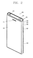
- FIG. 2 is a front perspective view of the mobile terminal according to an exemplary embodiment of the present invention
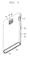
- FIG. 3 is a rear perspective view of the mobile terminal according to an exemplary embodiment of the present invention.
- the mobile terminal as illustrated has a bar-shaped terminal body 201.
- the mobile terminal can be applicable to various structures such as a slide type mobile terminal, a folder type mobile terminal, a swing type mobile terminal, a swivel type mobile terminal, and the like, having two or more bodies which are coupled to be relatively movable.
- the case (or casing, housing, cover, etc.) constituting the external appearance of the terminal body 201 includes a front case 202 and a rear case 203.
- Various electronic components are installed in the space between the front case 202 and the rear case 204.
- At least one intermediate case 203 may be additionally disposed between the front case 202 and the rear case 203.
- the portions of the intermediate case 203 exposed from the side surface of the terminal body has a single narrow, long stripe form, while the portions of the intermediate case 203 exposed from upper and lower ends are more recessed than the edge portions of the front case 202 and the rear case 203.
- the cases may be formed by injection-molding a synthetic resin or may be made of a metallic material such as stainless steel (STS) or titanium (Ti), etc.
- STS stainless steel
- Ti titanium
- a display unit 210 and an audio output unit 211 may be disposed on the front surface of the terminal body 201.
- the display unit 210 may be implemented as a liquid crystal display (LCD) module for visually displaying information, an organic light emitting diode (OLED) module, an e-paper, and the like.
- the display unit 210 may include a touch sensing unit allowing for an inputting operation in a tactile manner. Thus, when a point on the display unit 210 is touched, content corresponding to the touched position is inputted.
- the content inputted in the tactile manner may be characters, numbers, menu items that can be indicated or designated in various modes, and the like.
- the touch sensing unit may be light-transmissive to allow the display unit 210 to be seen, and may have a structure for enhancing visibility of the touch screen in a bright area.
- the audio output unit 211 may be implemented in the form of a receiver that transfers a speaker sound to the user's ear, or in the form of a loud speaker for outputting various alarm sounds or a multimedia reproduction sound of the mobile terminal 200.
- Side keys 212, 213, and 216 may be generally called a manipulation unit, and configured to receive a command for controlling the operation of the mobile terminal 200.
- Content inputted by the side keys 212, 213, and 216 may be variably set.
- a command for controlling the image input unit 218, a command for adjusting of the size of the sound outputted from the audio output unit 211, or a command for changing the display unit 210 to a touch recognition mode, and the like may be received.
- the side keys include a first side key 212 for adjusting a volume or the like, a second side key 213 for manipulating a camera, and a third side key 216 for performing other functions.
- the audio input unit 217 may be implemented in the form of a microphone in order to receive the user voice, other sounds, and the like.
- the interface unit 170 may be disposed at the side of the terminal body 201.
- the interface unit 170 is used as a communication link (or passage, path, etc.) through which the mobile terminal can exchange data or the like with an external device.
- the interface unit 170 may be implemented in the form of a connection port for connecting an earphone to the mobile terminal via a wireline or wireless means, a port for short-range communications (e.g., an Infrared Data Association (IrDA) port, a BluetoothTM port, a wireless LAN port, etc.), power supply ports for providing power to the mobile terminal, or the like.
- the interface unit 170 may be a card socket for accommodating a SIM (Subscriber Identification Module) card or a UIM (User Identity Module) card, or an external card such as a memory card for storing information.
- SIM Subscriber Identification Module
- UIM User Identity Module
- a jack 215 for connecting an ear set and an infrared port 214 for infrared communication, as sort of an interface unit 221.
- An image input unit may be disposed on the front surface or on the rear surface of the terminal body.
- FIG. 3 shows the case where the image input unit 218 is disposed on the rear surface of the terminal body.
- An image input unit disposed on the front surface of the terminal body may be used for capturing the user face when the user performs video call communication.
- a flash 220 and a mirror 219 may be additionally disposed adjacent to the image input unit 218.
- the flash 220 illuminates the subject.
- the mirror 219 allows the user to see himself when he wants to capture his own image (i.e., self-image capturing) by using the image input unit 218.
- a power supply unit is mounted on the rear surface of the terminal body 201 in order to supply power to the mobile terminal 200.
- the power supply unit may be configured to be installed in the terminal body 201 or may be directly detachably attached to the terminal body 201.
- the power supply unit 290 is installed on an inner surface of the rear case 203.
- FIG. 4 is a separated perspective view of a case locking structure of the mobile terminal, showing a rear case separated from a terminal body according to an exemplary embodiment of the present invention
- FIG. 5 is a plan view of an inner case constituting the terminal body
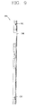
- FIG. 6 is a side view of the inner case of FIG. 5
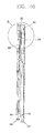
- FIG. 7 is a sectional view taken along line VII-VII of FIG. 5
- FIG. 8 is an internal plan view of a rear case according to an exemplary embodiment of the present invention
- FIG. 9 is a sectional view taken along line IX-IX of FIG. 8 .
- the rear case 203 may be formed so large as to cover the rear surface or the side surface of the terminal body 201.
- a battery 290, a memory socket 207, a user identification card (SIM) socket 208, and the like, are installed on the rear surface of the terminal body 201 which is exposed by separating the rear case 203.
- SIM user identification card
- the terminal body 201 includes a camera 218 to capture an image of a subject at a rear side.
- the camera 218 is installed within the camera mounting part 230, and the camera mounting part 230 is protruded from the rear surface of the terminal body 201 (See FIG. 7 ).
- the camera 218 tends to increase in size as it increasingly has a higher resolution, so the protruded camera mounting part 230 can be easily applicable for the case where the camera 218 has a high resolution.
- a camera hole 246 is formed on the rear case 203 to expose the camera mounting part 230, and an interface installation hole 247 is formed at one side of the rear case 203 in order to install an interface unit 221.
- the camera hole 246 and the interface installation hole 247 have a structure allowing for a free attachment to or detachment from the terminal body 201 of the rear case 203 without causing any trouble.
- the mobile terminal 200 includes a locking unit for maintaining the rear case 203 in a state of being mounted on the terminal body 201 (locked state) or releasing the locked state.
- the locking unit may be implemented by a plurality of elements formed at the rear case 203 and the terminal body 201.
- the locking unit may include locking recesses 250 and 251, locking protrusions 240 and 241, and horizontal locking units 245 and 255.
- the locking recesses 250 and 251 are formed on the rear surface of the terminal body 201, and the locking protrusions 240 and 241 are formed on the inner surface of the rear case 203.
- the locking recesses 250 and 251 include first locking recesses 250 disposed along the edges of the rear surface of the terminal body 201 and second locking recesses disposed at one side of the camera mounting part 230 and at one side of the battery.
- the locking recesses 250 and 251 may have slope guiding portions in the same direction so that the case can be locked or unlocked slopingly while the locking protrusions 240 and 241 are received.
- the slope guiding portion includes a first guide face 252 with which the locking protrusions 240 and 241 are brought into contact when the case is locked, and a second guide face 253 in a slope form to slopingly retreat the locking protrusions 240 and 241 when the case is unlocked.
- the locking protrusions 240 and 241 may slopingly enter the locking recesses 250 and 251 so as to be in a locked state or may be slopingly retreated so as to be unlocked.
- the angle and length of the slope face of the slope guide portion may be determined at which or with which at least one inner wall of the camera hole 246 of the rear case 203 evades the camera mounting part 230 when the rear case 203 is locked or unlocked.
- the locking protrusions 240 and 241 include the first locking protrusion 240 formed at a position corresponding to the first locking recess 250 and the second locking protrusion 241 formed at a position corresponding to the second locking recess 251.
- the first locking protrusion 240 includes a first slope face 242 and a second slope face 243 corresponding to the first guide face 252 and the second guide face 253 of the first locking recesses 250.
- the first slope face 242 is formed to have a slope form to allow the first guide face 252 to be brought into contact therewith when the rear case 203 is locked
- the second slope face 243 is formed to have a slope form to allow the second guide face 253 to be brought into contact therewith when the rear case 203 is unlocked.
- the combinations of the first slope face 242 and the first guide face 252 and the second slope face 243 and the second guide face 253 guarantee the sloping movement when the rear case 203 is moved toward the inner case 204 so as to be locked or when the rear case 203 is released from the inner case 205 so as to be separated.
- the sloping movement allows the camera mounting part 230 protruded from the camera hole 246 to move to a locking position or unlocking position without any restriction over the camera hole 246.
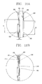
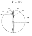
- FIGs. 10 and 11A to 11C illustrate such operations of the rear case.
- the rear case 203 in order to couple the rear case 203 to the inner case 205 in a state that the camera mounting part 230 is protruded by a certain height (d) from the rear surface of the inner case 205, the rear case 203 is positioned to be slightly lower than the inner case 205.
- the length L1 of the camera mounting part 230 corresponds to the length L2 of the camera hole 246 formed on the rear case 203 (namely, the length L1 and the length L2 are substantially equal), so in this case, the camera mounting part 230 and the camera hole 246 are not at corresponding positions.
- the camera mounting part 230 gradually fits the position of the camera hole 246.
- the combination of the first locking protrusion 240 and the second locking recess 251 involves the sloping movement of the rear case 203.
- the edge portions of the camera mounting part 230 or the camera hole 246 may be formed to be chamfered or rounded.
- a recessed portion 248 is formed with a certain depth at one side of the camera hole 246 at the inner surface of the rear case 203 in order to allow the rear case 203 not to be caught by the camera mounting part 230 while moving.
- the camera mounting part 230 is protruded from the camera hole 246 so as to be exposed as shown in FIG. 11C .
- a structure (horizontal locking unit) for preventing retreating, namely, a horizontal movement of the rear case 203, is provided between the rear case 203 and the terminal body 201.
- the horizontal locking unit includes a first protrusion 255 formed on the surface of the terminal body 201 and a second protrusion 245 formed on an inner surface of the rear case 203.
- the first protrusion 255 is positioned in the middle of the longer side of the rear case 203 that is likely to be relatively easily deformed.
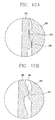
- FIG. 12A shows a state immediately before the rear case 203 is slopingly moved so as to be coupled to the inner case 205.
- the rear case 203 is elastically moved in a direction in which it has been moved due to the elastic restorative operation of the rear case 203 and the configuration of the first protrusion 255 and the second protrusion 245 ( FIG. 12C ). Then, the rear case 203 is coupled to the inner case 205. In this state, unless a reversing force of more than a certain value is applied, there is no relative horizontal movement between the first protrusion 255 and the second protrusion 245 by virtue of the configuration of the first protrusion 255 and the second protrusion 245. Thus, the locking protrusions 240 and 241 are maintained to be locked in the locking recesses 250 and 251, and the rear case 203 is not separated from the inner case 205.
- the second protrusion 245 reversely passes over the first protrusion 255.
- the rear case 203 is continuously moved in the direction in which it has been moved owing to the elastic restorative operation of the rear case 203 and the configuration of the first protrusion 255 and the second protrusion 245 ( FIGs. 12B and 12A ).
- the rear case 203 While the rear case 203 is horizontally moved, the rear case 203 becomes away also in a vertical direction due to the operations of the slope guide faces 252 and 253 of the locking recesses 250 and 251 and the slope faces 242 and 243 of the locking protrusions 240 and 241. Also, the movement of the rear case 203 in the vertical direction means that the inner wall of the camera hole 246 is freely released without being caught by the camera mounting part 230.
- FIGs. 13A and 13B illustrate operational states showing the relationship between the interface unit installation hole 247 formed at the rear case 203 and the interface unit 221 when the case is locked and when the case is unlocked.
- the interface unit installation hole 247 is formed at the side of the rear case 203.
- the length L4 of the interface unit installation hole 247 is larger than the sum L3 of the distance along which the locking protrusion is horizontally moved and the length of the interface unit between when the rear case 203 is locked or when the rear case 203 is unlocked.
- the interface unit 221 is positioned at one side of the interface unit installation hole 247 in a state that there is a certain gap g1 in a horizontal direction between the rear case 203 and the inner case 205, but when the rear case 203 is coupled to the inner case 205, the rear case 203 and the inner case 205 are positioned to be almost in contact with each other with a gap g2 therebetween and the interface unit 221 is positioned at the opposite side of the interface unit installation hole 247.
- the rear case 203 is slopingly moved to be coupled to the terminal body 201 or slopingly moved to be separated from the terminal body 201.
- the rear case 203 can be freely moved without being interfered with by any portions of the terminal body 201.
- the camera hole 246 has the length corresponding to the camera mounting part 230, complicated assembling lines can be omitted or generation of a gap can be prevented.
- the rear case while the rear case is coupled to or separated from the terminal body, it is slopingly moved with respect to the terminal body, so the camera hole of the rear case can be freely moved without being restricted by the camera mounting part protruded from the terminal body.
- Such disposition can prevent aesthetic degradation of an external appearance otherwise because the camera hole of the case is formed to be large.
Landscapes
- Engineering & Computer Science (AREA)
- Signal Processing (AREA)
- Telephone Set Structure (AREA)
- Telephone Function (AREA)
Description
- The present invention relates to a case attachment structure for a mobile terminal.
- A mobile terminal is a device that can be carried around and has one or more functions such as voice and video call communication, inputting and outputting information, storing data, and the like.
- As such functions become more diversified, the mobile terminal can support more complicated functions such as capturing images or video, reproducing music or video files, playing games, receiving broadcast signals, and the like. By comprehensively and collectively implementing such functions, the mobile terminal may be embodied in the form of a multimedia player or device.
- In order to implement various functions of such multimedia players or devices, the multimedia player requires sufficient support in terms of hardware or software, for which numerous attempts are being made and implemented. For example, a user interface allowing users to easily and conveniently search for and select one or more functions is provided.
- A case is detachably coupled to a rear surface of a mobile terminal to replace a battery or the like. In this case, however, portions of the case itself or the means used for attaching the case are exposed, which is asthetically unpleasing and undesirable to the user.
-
US2006/079128 andUS2004/212555 each disclose a mobile terminal having a push-fit case, which includes a hole for an integral camera.EP1367802 discloses a mobile terminal having a hinged push-fit case. - Accordingly, one object of the present invention is to address the above-noted and other problems.
- Another object of the present invention is to provide a mobile terminal with a case attachment structure providing a simple case form without exposing a fixing unit of the case when the case is fixed to a terminal body.
- To achieve these and other advantages and in accordance with the purpose of the present invention, as embodied and broadly described herein, the present invention provides in one aspect a mobile terminal according to claim 1.
- The locking recesses may include a plurality of first locking recesses formed along edges of the rear surface of the terminal body; and at least one locking recess formed at one portion of the camera mounting part.
- The slope guiding portion of the locking recesses may include a first guide face in a sloped form with which the slope face of the locking protrusions are brought into contact when the case is locked; and a second guide face in a slope form slopingly retreating the locking protrusions when the case is unlocked.
- The slope face of the locking protrusions may include a first slope face formed in a slope form to allow the first guide face to be brought into contact therewith; and a second slope face formed in a sloped form to allow the second guide face to be brought into contact therewith when the case is unlocked.
- The slope face of the slope guiding portion of the locking recesses may have an angle and a length at which and with which at least one inner wall of the camera hole of the case evades the camera mounting part when the case is locked or unlocked.
- The case may be formed to cover the rear surface of the terminal body and the side surface of the terminal body, and the locking protrusions may be disposed at the side portion of the case.
- The case may include an interface unit installation hole in which an interface unit mounted at the terminal body is to be installed, and the length of the interface unit installation hole may be larger than the sum of the distance along which the locking protrusion is horizontally moved when the case is locked and when the case is unlocked and the length of the interface unit.
- The horizontal locking unit may include: a first protrusion formed on the surface of the terminal body; and a second protrusion formed on an inner surface of the case and configured to be movable in contact with the first protrusion.
- The camera mounting part may be formed to have a length corresponding to the camera hole.
- A recessed portion may be formed with a certain depth at one side of the camera hole on the inner surface of the case in order to allow the case not to be caught by the camera mounting part.
- Further scope of applicability of the present invention will become apparent from the detailed description given hereinafter. However, it should be understood that the detailed description and specific examples, while indicating preferred embodiments of the invention, are given by illustration only, since various changes and modifications within the scope of the invention will become apparent to those skilled in the art from this detailed description.
- The present invention will become more fully understood from the detailed description given hereinbelow and the accompanying drawings, which are given by illustration only, and thus are not limitative of the present invention, and wherein:
-
FIG. 1 is a schematic block diagram of a mobile terminal according to an exemplary embodiment of the present invention; -
FIG. 2 is a front perspective view of the mobile terminal according to an exemplary embodiment of the present invention; -
FIG. 3 is a rear perspective view of the mobile terminal according to an exemplary embodiment of the present invention; -
FIG. 4 is a separated perspective view of a case locking structure of the mobile terminal, showing a rear case separated from a terminal body according to an exemplary embodiment of the present invention; -
FIG. 5 is a plan view of an inner case constituting the terminal body; -
FIG. 6 is a side view of the inner case ofFIG. 5 ; -
FIG. 7 is a sectional view taken along line VII-VII ofFIG. 5 ; -
FIG. 8 is an internal plan view of a rear case according to an exemplary embodiment of the present invention; -
FIG. 9 is a sectional view taken along line IX-IX ofFIG. 8 ; -
FIG. 10 is a sectional view showing a configuration before the rear case is coupled to the inner case; -
FIGs. 11A to 11C show operational states for explaining the process of coupling the rear case to the inner case; -
FIGs. 12A to 12C are sectional views showing the structure of horizontal locking units and operational states according to an exemplary embodiment of the present invention; and -
FIGs. 13A and 13B illustrate operational states showing the relationship between an interface unit installation hole formed at the rear case and an interface unit when the case is locked and when the case is unlocked. - The mobile terminal according to exemplary embodiments of the present invention will now be described with reference to the accompanying drawings. In the following description, usage of suffixes such as 'module', 'part' or 'unit' used for referring to elements is given merely to facilitate explanation of the present invention, without having any significant meaning by itself.
-
FIG. 1 is a block diagram of a mobile terminal according to an exemplary embodiment of the present invention. - The
mobile terminal 100 may include awireless communication unit 110, an A/V (Audio/Video)input unit 120, auser input unit 130, asensing unit 140, anoutput unit 150, amemory unit 160, aninterface unit 170, acontroller 180, and apower supply unit 190, etc. The components as shown inFIG. 1 are not a requirement, and greater or fewer components may alternatively be implemented. - The components will be described in detail as follows.
- The
wireless communication unit 110 may include one or more components allowing radio communication between themobile terminal 100 and a wireless communication system or a network in which the mobile terminal is located. For example, the wireless communication unit may include abroadcast receiving module 111, amobile communication module 112, awireless Internet module 113, a short-range communication module 114, and alocation information module 115, etc. - The
broadcast receiving module 111 receives broadcast signals and/or broadcast associated information from an external broadcast management server via a broadcast channel. The broadcast channel may include a satellite channel and a terrestrial channel. The broadcast management server may refer to a server that generates and transmits a broadcast signal and/or broadcast associated information or a server that receives a previously generated broadcast signal and/or broadcast associated information and transmits the same to a terminal. The broadcast signal may include not only a TV broadcast signal, a radio broadcast signal and a data broadcast signal, but also a broadcast signal obtained by coupling a data broadcast signal to the TV or radio broadcast signal. - The broadcast associated information may be information related to a broadcast channel, a broadcast program or a broadcast service provider.
- The broadcast associated information may be provided via a mobile communication network. In this case, the broadcast associated information may be received by the
mobile communication module 112. - The broadcast associated information may exist in various forms. For example, it may exist in the form of an electronic program guide (EPG) of digital multimedia broadcasting (DMB), electronic service guide (ESG) of digital video broadcast-handheld (DVB-H), etc.
- The
broadcast receiving module 111 may receive digital broadcast signals by using digital broadcast systems such as multimedia broadcasting-terrestrial (DMB-T), digital multimedia broadcastingsatellite (DMB-S), media forward link only (MediaFLO®), digital video broadcast-handheld (DVB-H), integrated services digital broadcast-terrestrial (ISDB-T), etc. Thebroadcast receiving module 111 may be configured to be suitable for any other broadcast systems as well as the above-described digital broadcast systems. - Broadcast signals and/or broadcast-associated information received via the
broadcast receiving module 111 may be stored in thememory unit 160. - The
mobile communication module 112 transmits and receives radio signals to and from at least one of a base station, an external terminal and a server. Such radio signals may include a voice call signal, a video call signal or various types of data according to text/multimedia message transmission and reception. - The
wireless Internet module 113 refers to a module for a wireless Internet access. This module may be internally or externally coupled to the terminal. The wireless Internet technique may include a WLAN (Wireless LAN) (Wi-Fi), Wibro (Wireless broadband), Wimax (World Interoperability for Microwave Access), HSDPA (High Speed Downlink Packet Access), etc. - The short-
range communication module 114 refers to a module for short-range communication. As the short range communication technologies, Bluetooth™, radio frequency identification (RFID), infrared data association (IrDA), ultra-wideband (UWB), ZigBee™, etc., may be used. - The
location information module 115 is a module for checking or acquiring a location (or position) of the mobile terminal. A typical example of the location information module is a GPS (Global Positioning System). According to the current technology, theGPS module 115 calculates distance information from three or more satellites and accurate time information and applies trigonometry to the calculated information to thereby accurately calculate three-dimensional current location information according to latitude, longitude, and altitude. Currently, a method for calculating location and time information by using three satellites and correcting an error of the calculated location and time information by using another one satellite. In addition, theGPS module 115 can calculate speed information by continuously calculating the current location in real time. - The A/
V input unit 120 is configured to receive an audio or video signal. The A/V input unit 120 may include acamera 121 and amicrophone 122. Thecamera 121 processes image data of still pictures or video obtained by an image capture device in a video capturing mode or an image capturing mode. The processed image frames may be displayed on a display unit 151 (or other visual output device). - The image frames processed by the
camera 121 may be stored in thememory unit 160 or transmitted via thewireless communication unit 110. Two ormore cameras 121 may be provided according to the configuration of the mobile terminal. - The
microphone 122 may receive sounds (audible data) via a microphone or the like in a phone call mode, a recording mode, a voice recognition mode, and the like, and can process such sounds into audio data. The processed audio (voice) data may be converted for output into a format transmittable to a mobile communication base station via themobile communication module 112 in case of the phone call mode. Themicrophone 122 may implement various types of noise canceling (or suppression) algorithms to cancel (or suppress) noise or interference generated in the course of receiving and transmitting audio signals. - The user input unit 130 (or other user input device) may generate key input data from commands entered by a user to control various operations of the mobile terminal. The
user input unit 130 allows the user to enter various types of information, and may include a keypad, a dome switch, a touch pad (e.g., a touch sensitive member that detects changes in resistance, pressure, capacitance, etc. due to being contacted) a jog wheel, a jog switch, and the like. In particular, when the touch pad is overlaid on thedisplay unit 151 in a layered manner, it may form a touch screen. - The
sensing unit 140 detects a current status (or state) of themobile terminal 100 such as an opened or closed state of themobile terminal 100, a location of themobile terminal 100, the presence or absence of user contact with the mobile terminal 100 (i.e., touch inputs), the orientation of themobile terminal 100, an acceleration or deceleration movement and direction of themobile terminal 100, etc., and generates commands or signals for controlling the operation of themobile terminal 100. For example, when themobile terminal 100 is implemented as a slide type mobile phone, thesensing unit 140 may sense whether the slide phone is opened or closed. In addition, thesensing unit 140 can detect whether or not thepower supply unit 190 supplies power or whether or not theinterface unit 170 is coupled with an external device. Meanwhile, thesensing unit 140 may include aproximity sensor 141. Theproximity sensor 141 will be described in relation to a touch screen later. - The
interface unit 170 serves as an interface by which at least one external device may be connected with themobile terminal 100. For example, the external devices may include wired or wireless headset ports, an external power supply ports, wired or wireless data ports, memory card ports, ports for connecting a device having an identification module, audio input/output (I/O) ports, video I/O ports, earphone ports, or the like. - The identification module may be a chip that stores various information for authenticating user's authority for using the
mobile terminal 100 and may include a user identity module (UIM), a subscriber identity module (SIM) a universal subscriber identity module (USIM), and the like. In addition, the device having the identification module (referred to as the 'identifying device', hereinafter) may take the form of a smart card. Accordingly, the identifying device may be connected with the terminal 100 via a port or other connection means. Theinterface unit 170 may be used to receive inputs (e.g., data, information, power, etc.) from an external device and transfer the received inputs to one or more elements within themobile terminal 100 or may be used to transfer data between the mobile terminal and an external device. - In addition, when the
mobile terminal 100 is connected with an external cradle, theinterface unit 170 may serve as a conduit to allow power from the cradle to be supplied therethrough to themobile terminal 100 or may serve as a conduit to allow various command signals inputted from the cradle to be transferred to the mobile terminal therethrough. Various command signals or power inputted from the cradle may be operated as a signal for recognizing that the mobile terminal is accurately mounted on the cradle. - The
output unit 150 is configured to provide outputs in a visual, audible, and/or tactile manner (e.g., audio signal, video signal, alarm signal, vibration signal, etc.). Theoutput unit 150 may include thedisplay unit 151, anaudio output module 152, analarm unit 153, and the like. - The
display unit 151 may display information processed in themobile terminal 100. For example, when themobile terminal 100 is in a phone call mode, thedisplay unit 151 may display a User Interface (UI) or a Graphic User Interface (GUI) associated with a call or other communication (such as text messaging, multimedia file downloading, etc.). When themobile terminal 100 is in a video call mode or image capturing mode, thedisplay unit 151 may display a captured image and/or received image, a UI or GUI that shows videos or images and functions related thereto, and the like. - Meanwhile, when the
display unit 151 and the touch pad are overlaid in a layered manner to form a touch screen, thedisplay unit 151 may function as both an input device and an output device. Thedisplay unit 151 may include at least one of a Liquid Crystal Display (LCD), a Thin Film Transistor-LCD (TFT-LCD), an Organic Light Emitting Diode (OLED) display, a flexible display, a three-dimensional (3D) display, or the like. - The
proximity sensor 141 may be disposed within or near the touch screen. Theproximity sensor 141 is a sensor for detecting the presence or absence of an object relative to a certain detection surface or an object that exists nearby by using the force of electromagnetism or infrared rays without a physical contact. Without theproximity sensor 141, if the touch screen is an electrostatic type, the approach of a pointer (stylus) can be detected based on a change in a field according to the approach of the pointer. - The
audio output module 152 may convert and output as sound audio data received from thewireless communication unit 110 or stored in thememory unit 160 in a call signal reception mode, a call mode, a record mode, a voice recognition mode, a broadcast reception mode, and the like. Also, theaudio output module 152 may provide audible outputs related to a particular function performed by the mobile terminal 100 (e.g., a call signal reception sound, a message reception sound, etc.). Theaudio output module 152 may include a speaker, a buzzer, or other sound generating device. - The alarm unit 153 (or other type of user notification means) may provide outputs to inform about the occurrence of an event of the
mobile terminal 100. Typical events may include call reception, message reception, key signal inputs, a touch input etc. In addition to audio or video outputs, thealarm unit 153 may provide outputs in a different manner to inform about the occurrence of an event. For example, thealarm unit 153 may provide an output in the form of vibrations (or other tactile or sensible outputs). When a call, a message, or some other incoming communication is received, thealarm unit 153 may provide tactile outputs (i.e., vibrations) to inform the user thereof. By providing such tactile outputs, the user can recognize the occurrence of various events even if his mobile phone is in the user's pocket. Outputs informing about the occurrence of an event may be also provided via thedisplay unit 151 or theaudio output module 152. - The
memory unit 160 may store software programs or the like used for the processing and controlling operations performed by thecontroller 180, or may temporarily store data (e.g., a phonebook, messages, still images, video, etc.) that have been outputted or which are to be outputted. In addition, thememory unit 160 may store data regarding various patterns of vibrations and sounds outputted when a touch is applied onto the touch screen. - The
memory unit 160 may include at least one type of storage medium including a Flash memory, a hard disk, a multimedia card, a card-type memory (e.g., SD or DX memory, etc), a Random Access Memory (RAM), a Static Random Access Memory (SRAM), a Read-Only Memory (ROM), an Electrically Erasable Programmable Read-Only Memory (EEPROM), a Programmable Read-Only Memory (PROM), a magnetic memory, a magnetic disk, an optical disk, and the like. Also, themobile terminal 100 may cooperate with a network storage device that performs the storage function of thememory unit 160 over a network connection. - The
controller 180 typically controls the general operations of the mobile terminal. For example, thecontroller 180 performs controlling and processing associated with voice calls, data communications, video calls, and the like. In addition, thecontroller 180 may include amultimedia module 181 for reproducing (or playing back) multimedia data. Themultimedia module 181 may be configured within thecontroller 180 or may be configured to be separate from thecontroller 180. - The
controller 180 may perform a pattern recognition processing to recognize a handwriting input or a picture drawing input performed on the touch screen as characters or images. - The
power supply unit 190 receives external power (via a power cable connection) or internal power (via a battery of the mobile terminal) and supplies appropriate power required for operating respective elements and components under the control of thecontroller 180. -
FIG. 2 is a front perspective view of the mobile terminal according to an exemplary embodiment of the present invention, andFIG. 3 is a rear perspective view of the mobile terminal according to an exemplary embodiment of the present invention. - The mobile terminal as illustrated has a bar-shaped
terminal body 201. However, without being limited thereto, the mobile terminal can be applicable to various structures such as a slide type mobile terminal, a folder type mobile terminal, a swing type mobile terminal, a swivel type mobile terminal, and the like, having two or more bodies which are coupled to be relatively movable. - The case (or casing, housing, cover, etc.) constituting the external appearance of the
terminal body 201 includes afront case 202 and arear case 203. Various electronic components are installed in the space between thefront case 202 and therear case 204. At least oneintermediate case 203 may be additionally disposed between thefront case 202 and therear case 203. With reference toFIG. 2 , the portions of theintermediate case 203 exposed from the side surface of the terminal body has a single narrow, long stripe form, while the portions of theintermediate case 203 exposed from upper and lower ends are more recessed than the edge portions of thefront case 202 and therear case 203. - The cases may be formed by injection-molding a synthetic resin or may be made of a metallic material such as stainless steel (STS) or titanium (Ti), etc. Like
- A
display unit 210 and anaudio output unit 211 may be disposed on the front surface of theterminal body 201. - The
display unit 210 may be implemented as a liquid crystal display (LCD) module for visually displaying information, an organic light emitting diode (OLED) module, an e-paper, and the like. Thedisplay unit 210 may include a touch sensing unit allowing for an inputting operation in a tactile manner. Thus, when a point on thedisplay unit 210 is touched, content corresponding to the touched position is inputted. The content inputted in the tactile manner may be characters, numbers, menu items that can be indicated or designated in various modes, and the like. The touch sensing unit may be light-transmissive to allow thedisplay unit 210 to be seen, and may have a structure for enhancing visibility of the touch screen in a bright area. - The
audio output unit 211 may be implemented in the form of a receiver that transfers a speaker sound to the user's ear, or in the form of a loud speaker for outputting various alarm sounds or a multimedia reproduction sound of themobile terminal 200. -
Side keys mobile terminal 200. Content inputted by theside keys image input unit 218, a command for adjusting of the size of the sound outputted from theaudio output unit 211, or a command for changing thedisplay unit 210 to a touch recognition mode, and the like, may be received. With reference toFIGs. 2 and3 , the side keys include afirst side key 212 for adjusting a volume or the like, asecond side key 213 for manipulating a camera, and athird side key 216 for performing other functions. - The
audio input unit 217 may be implemented in the form of a microphone in order to receive the user voice, other sounds, and the like. - The
interface unit 170 may be disposed at the side of theterminal body 201. Theinterface unit 170 is used as a communication link (or passage, path, etc.) through which the mobile terminal can exchange data or the like with an external device. For example, theinterface unit 170 may be implemented in the form of a connection port for connecting an earphone to the mobile terminal via a wireline or wireless means, a port for short-range communications (e.g., an Infrared Data Association (IrDA) port, a Bluetooth™ port, a wireless LAN port, etc.), power supply ports for providing power to the mobile terminal, or the like. Also, theinterface unit 170 may be a card socket for accommodating a SIM (Subscriber Identification Module) card or a UIM (User Identity Module) card, or an external card such as a memory card for storing information. - With reference to
FIG. 2 , on the upper end face of the terminal body, there are formed ajack 215 for connecting an ear set and aninfrared port 214 for infrared communication, as sort of aninterface unit 221. - An image input unit may be disposed on the front surface or on the rear surface of the terminal body.
FIG. 3 shows the case where theimage input unit 218 is disposed on the rear surface of the terminal body. An image input unit disposed on the front surface of the terminal body may be used for capturing the user face when the user performs video call communication. - A
flash 220 and amirror 219 may be additionally disposed adjacent to theimage input unit 218. When an image of the subject is captured, theflash 220 illuminates the subject. Themirror 219 allows the user to see himself when he wants to capture his own image (i.e., self-image capturing) by using theimage input unit 218. - A power supply unit is mounted on the rear surface of the
terminal body 201 in order to supply power to themobile terminal 200. The power supply unit may be configured to be installed in theterminal body 201 or may be directly detachably attached to theterminal body 201. With reference toFIG. 4 , thepower supply unit 290 is installed on an inner surface of therear case 203. -
FIG. 4 is a separated perspective view of a case locking structure of the mobile terminal, showing a rear case separated from a terminal body according to an exemplary embodiment of the present invention,FIG. 5 is a plan view of an inner case constituting the terminal body,FIG. 6 is a side view of the inner case ofFIG. 5 ,FIG. 7 is a sectional view taken along line VII-VII ofFIG. 5 ,FIG. 8 is an internal plan view of a rear case according to an exemplary embodiment of the present invention, andFIG. 9 is a sectional view taken along line IX-IX ofFIG. 8 . - As shown in
FIG. 4 , therear case 203 may be formed so large as to cover the rear surface or the side surface of theterminal body 201. Abattery 290, amemory socket 207, a user identification card (SIM)socket 208, and the like, are installed on the rear surface of theterminal body 201 which is exposed by separating therear case 203. These components can be replaced by detaching only therear case 203, so the external appearance can be significantly improved compared with the case where an opening and closing cover unit is provided for each component. - The
terminal body 201 includes acamera 218 to capture an image of a subject at a rear side. Thecamera 218 is installed within thecamera mounting part 230, and thecamera mounting part 230 is protruded from the rear surface of the terminal body 201 (SeeFIG. 7 ). Thecamera 218 tends to increase in size as it increasingly has a higher resolution, so the protrudedcamera mounting part 230 can be easily applicable for the case where thecamera 218 has a high resolution. - A
camera hole 246 is formed on therear case 203 to expose thecamera mounting part 230, and aninterface installation hole 247 is formed at one side of therear case 203 in order to install aninterface unit 221. Thecamera hole 246 and theinterface installation hole 247 have a structure allowing for a free attachment to or detachment from theterminal body 201 of therear case 203 without causing any trouble. - In order to attach or detach the
rear case 203, themobile terminal 200 includes a locking unit for maintaining therear case 203 in a state of being mounted on the terminal body 201 (locked state) or releasing the locked state. The locking unit may be implemented by a plurality of elements formed at therear case 203 and theterminal body 201. - The locking unit may include locking
recesses protrusions horizontal locking units - The locking recesses 250 and 251 are formed on the rear surface of the
terminal body 201, and the lockingprotrusions rear case 203. With reference toFIGs. 4 and5 , the locking recesses 250 and 251 include first locking recesses 250 disposed along the edges of the rear surface of theterminal body 201 and second locking recesses disposed at one side of thecamera mounting part 230 and at one side of the battery. The locking recesses 250 and 251 may have slope guiding portions in the same direction so that the case can be locked or unlocked slopingly while the lockingprotrusions - As shown in
FIGs. 4 and6 , the slope guiding portion includes afirst guide face 252 with which the lockingprotrusions second guide face 253 in a slope form to slopingly retreat the lockingprotrusions first guide face 252 and thesecond guide face 253, the lockingprotrusions camera hole 246 of therear case 203 evades thecamera mounting part 230 when therear case 203 is locked or unlocked. - With reference to
FIG. 4 , the lockingprotrusions first locking protrusion 240 formed at a position corresponding to thefirst locking recess 250 and thesecond locking protrusion 241 formed at a position corresponding to thesecond locking recess 251. Thefirst locking protrusion 240 includes afirst slope face 242 and asecond slope face 243 corresponding to thefirst guide face 252 and thesecond guide face 253 of the first locking recesses 250. Namely, thefirst slope face 242 is formed to have a slope form to allow thefirst guide face 252 to be brought into contact therewith when therear case 203 is locked, and thesecond slope face 243 is formed to have a slope form to allow thesecond guide face 253 to be brought into contact therewith when therear case 203 is unlocked. The combinations of thefirst slope face 242 and thefirst guide face 252 and thesecond slope face 243 and thesecond guide face 253 guarantee the sloping movement when therear case 203 is moved toward theinner case 204 so as to be locked or when therear case 203 is released from theinner case 205 so as to be separated. In addition, the sloping movement allows thecamera mounting part 230 protruded from thecamera hole 246 to move to a locking position or unlocking position without any restriction over thecamera hole 246. -
FIGs. 10 and11A to 11C illustrate such operations of the rear case. Namely, as shown inFIG. 11A , in order to couple therear case 203 to theinner case 205 in a state that thecamera mounting part 230 is protruded by a certain height (d) from the rear surface of theinner case 205, therear case 203 is positioned to be slightly lower than theinner case 205. The length L1 of thecamera mounting part 230 corresponds to the length L2 of thecamera hole 246 formed on the rear case 203 (namely, the length L1 and the length L2 are substantially equal), so in this case, thecamera mounting part 230 and thecamera hole 246 are not at corresponding positions. - As shown in
FIG. 11B , as thesecond locking protrusion 241 enters thesecond locking recess 251 to start to move slopingly, thecamera mounting part 230 gradually fits the position of thecamera hole 246. Of course, the combination of thefirst locking protrusion 240 and thesecond locking recess 251 involves the sloping movement of therear case 203. Conversely, in order to prevent the edge portions of thecamera mounting part 230 from coming in contact with the inner wall of thecamera hole 246 when thecamera hole 246 is slopingly moved, the edge portions of thecamera mounting part 230 or thecamera hole 246 may be formed to be chamfered or rounded. - In addition, preferably, a recessed
portion 248 is formed with a certain depth at one side of thecamera hole 246 at the inner surface of therear case 203 in order to allow therear case 203 not to be caught by thecamera mounting part 230 while moving. - When the
second locking protrusion 241 completely enters thesecond locking recess 251, thecamera mounting part 230 is protruded from thecamera hole 246 so as to be exposed as shown inFIG. 11C . - Even when the
rear case 203 slopingly moves so the lockingprotrusions protrusions rear case 203, is provided between therear case 203 and theterminal body 201. - In more detail, as shown in
FIG. 4 , the horizontal locking unit includes afirst protrusion 255 formed on the surface of theterminal body 201 and asecond protrusion 245 formed on an inner surface of therear case 203. Thefirst protrusion 255 is positioned in the middle of the longer side of therear case 203 that is likely to be relatively easily deformed. - The operation of the
first protrusion 255 and thesecond protrusion 245 will now be described with reference toFIGs. 12A to 12C .FIG. 12A shows a state immediately before therear case 203 is slopingly moved so as to be coupled to theinner case 205. - In this state, when the
rear case 203 is slopingly moved with respect to theinner case 205, thefirst protrusion 255 and thesecond protrusion 245 are relatively moved according to the horizontal movement component to widen the side of the rear case 203 (FIG. 12B ). - Instantly when the
first protrusion 255 and thesecond protrusion 245 pass through the peak, therear case 203 is elastically moved in a direction in which it has been moved due to the elastic restorative operation of therear case 203 and the configuration of thefirst protrusion 255 and the second protrusion 245 (FIG. 12C ). Then, therear case 203 is coupled to theinner case 205. In this state, unless a reversing force of more than a certain value is applied, there is no relative horizontal movement between thefirst protrusion 255 and thesecond protrusion 245 by virtue of the configuration of thefirst protrusion 255 and thesecond protrusion 245. Thus, the lockingprotrusions rear case 203 is not separated from theinner case 205. - Conversely, if a force of more than a certain value is applied in the opposite direction in the sate of
FIG. 12C , thesecond protrusion 245 reversely passes over thefirst protrusion 255. When thesecond protrusion 245 passes through the peak of thefirst protrusion 255, therear case 203 is continuously moved in the direction in which it has been moved owing to the elastic restorative operation of therear case 203 and the configuration of thefirst protrusion 255 and the second protrusion 245 (FIGs. 12B and 12A ). While therear case 203 is horizontally moved, therear case 203 becomes away also in a vertical direction due to the operations of the slope guide faces 252 and 253 of the locking recesses 250 and 251 and the slope faces 242 and 243 of the lockingprotrusions rear case 203 in the vertical direction means that the inner wall of thecamera hole 246 is freely released without being caught by thecamera mounting part 230. -
FIGs. 13A and 13B illustrate operational states showing the relationship between the interfaceunit installation hole 247 formed at therear case 203 and theinterface unit 221 when the case is locked and when the case is unlocked. - As shown in
FIGs. 13A and 13B , the interfaceunit installation hole 247 is formed at the side of therear case 203. In order to prevent the interfaceunit installation hole 247 from being limited by theinterface unit 221 due to the horizontal movement made when therear case 203 is locked or unlocked, the length L4 of the interfaceunit installation hole 247 is larger than the sum L3 of the distance along which the locking protrusion is horizontally moved and the length of the interface unit between when therear case 203 is locked or when therear case 203 is unlocked. - Accordingly, as shown in
FIG. 13A , before therear case 203 is coupled to theinner case 205, theinterface unit 221 is positioned at one side of the interfaceunit installation hole 247 in a state that there is a certain gap g1 in a horizontal direction between therear case 203 and theinner case 205, but when therear case 203 is coupled to theinner case 205, therear case 203 and theinner case 205 are positioned to be almost in contact with each other with a gap g2 therebetween and theinterface unit 221 is positioned at the opposite side of the interfaceunit installation hole 247. - With such configuration, the
rear case 203 is slopingly moved to be coupled to theterminal body 201 or slopingly moved to be separated from theterminal body 201. In this process, therear case 203 can be freely moved without being interfered with by any portions of theterminal body 201. In particular, because thecamera hole 246 has the length corresponding to thecamera mounting part 230, complicated assembling lines can be omitted or generation of a gap can be prevented. - As so far described, in the mobile terminal according to the exemplary embodiment of the present invention, while the rear case is coupled to or separated from the terminal body, it is slopingly moved with respect to the terminal body, so the camera hole of the rear case can be freely moved without being restricted by the camera mounting part protruded from the terminal body. Such disposition can prevent aesthetic degradation of an external appearance otherwise because the camera hole of the case is formed to be large.
- As the exemplary embodiments may be implemented in several forms without departing from the characteristics thereof, it should also be understood that the above-described embodiments are not limited by any of the details of the foregoing description, unless otherwise specified, but rather should be construed broadly within its scope as defined in the appended claims. Therefore, various changes and modifications that fall within the scope of the claims, or equivalents of such scope are therefore intended to be embraced by the appended claims.
Claims (12)
- A mobile terminal (200) comprising:a terminal body (201);a camera mount (230) installed in the terminal body and configured to protrude from a rear surface of the terminal body;a camera (218) mounted in the camera mount;a case (203) detachably coupled to the rear surface of the terminal body such that the case has a locked configuration and an unlocked configuration, the case (203) comprising a camera hole (246) configured to expose the camera mount (230) such that the camera (218) protrudes from the camera hole (246) when the case (203) is in the locked configuration, anda locking unit having a plurality of elements formed on the case and the terminal body,wherein the case (203) slides in a vertical direction at an angle with respect to the terminal body (201) when the case (203) is moved between the locked configuration and the unlocked configuration such that the camera hole (246) moves without being restricted by the camera mount (230),wherein the plurality of elements comprise:a plurality of locking recesses (250, 251) formed on the rear surface of the terminal body (201) each having a slope guiding portion (252, 253) in the same direction;locking protrusions (240, 241) formed on an inner surface of the case (203) and corresponding to the plurality of locking recesses (250, 251), each locking protrusion (240, 241) having at least one slope face (242,243) that is brought into contact with one of the corresponding plurality of slope guiding portions (252, 253); andhorizontal locking units (245, 255) formed on the inner surface of the terminal body (201) and the case (203) and configured to interrupt retreat of the locking protrusions (240, 241) when the locking protrusions (240, 241) slopingly enter the slope guiding portions (252, 253) of the plurality of locking recesses (250, 251)wherein each of the horizontal locking units (245, 255) comprises:a first protrusion (245) formed on the terminal body (201); anda second protrusion (255) formed on the inner surface of the case (203) and configured to move in contact with the first protrusion (245).
- The mobile terminal (200) of claim 1, wherein each of the plurality of locking recesses (250, 251) comprise:a plurality of first locking recesses (250) formed along edges of the rear surface of the terminal body; andat least one locking recess (251) formed on one portion of the camera mount (230).
- The mobile terminal (200) of any one of claims 1 to 2, wherein the camera mount (230) protrudes from the camera hole (246) when the locking protrusions (240, 241) completely enter the locking recesses (250, 251).
- The mobile terminal (200) of any one of claims 1 to 3, wherein the slope guiding portion (252, 253) of each of the plurality of locking recesses (250, 251) comprises:a first sloped guide face (252) with which the at least one slope face of the corresponding locking protrusion (240, 241) is brought into contact when the case (203) is in the locked configuration; anda second sloped guide face (253) configured to retreat the corresponding locking protrusion (240,241) when the case (203) is in the unlocked configuration.
- The mobile terminal (200) of claim 4, wherein the at least one slope face (242, 243) of each of the locking protrusions (240, 241) comprises:a first sloped face (242) configured to allow the first sloped guide face (252) to be brought into contact with the first sloped face (242) when the case (203) is in the locked configuration; anda second sloped face (243) configured to allow the second sloped guide face (253) to be brought into contact with the second sloped face (243) when the case is in the unlocked configuration.
- The mobile terminal (200) of any one of claims 1 to 5, wherein a slope face of the slope guiding portion (252,253) of each of the plurality of the locking recesses has an angle and a length such that at least one inner wall of the camera hole (246) avoids contact with the camera mount (230) when the case is moved into the locked or unlocked configuration.
- The mobile terminal (200) of claim 6, wherein edge portions of at least the camera mount (230) or camera (218) hole are chamfered or rounded.
- The mobile terminal (200) of claims 6 or 7, further comprising an interface unit (221) and wherein:the case (203) comprises an interface unit installation hole (247) configured to receive the interface unit (221); anda length (L4) of the interface unit installation hole is greater than a sum (L3) of a length of the interface unit (221) and a distance along which each of the locking protrusions (240, 241) is horizontally moved when the case (203) is moved into the locked configuration or the unlocked configuration.
- The mobile terminal (200) of any one of claims 1 to 8, wherein:the case (203) covers the rear surface (201) of the terminal body (201) and a side surface of the terminal body (201); andthe locking protrusions (240) are located at a side portion of the case (203).
- The mobile terminal (200) of any one of claims 1 to 9, wherein the camera mount (230) has a length corresponding to the camera hole (246).
- The mobile terminal (200) of any one of claims 1 to 10, further comprising a recessed portion (248) on the inner surface of the case (203) at one side of the camera hole (246) and having a certain depth such that the case (203) does not contact the camera mount (230) when the case (203) is moved between the locked configuration and the unlocked configuration.
- The mobile terminal (200) of any one of claims 1 to 11, wherein the rear surface of the terminal body (201) is exposed when the case (203) is in the unlocked configuration.
Applications Claiming Priority (1)
| Application Number | Priority Date | Filing Date | Title |
|---|---|---|---|
| KR1020090085096A KR101613928B1 (en) | 2009-09-09 | 2009-09-09 | Portable terminal |
Publications (3)
| Publication Number | Publication Date |
|---|---|
| EP2296352A2 EP2296352A2 (en) | 2011-03-16 |
| EP2296352A3 EP2296352A3 (en) | 2013-01-02 |
| EP2296352B1 true EP2296352B1 (en) | 2014-11-05 |
Family
ID=43221938
Family Applications (1)
| Application Number | Title | Priority Date | Filing Date |
|---|---|---|---|
| EP10174961.2A Not-in-force EP2296352B1 (en) | 2009-09-09 | 2010-09-01 | Mobile terminal |
Country Status (4)
| Country | Link |
|---|---|
| US (1) | US8456809B2 (en) |
| EP (1) | EP2296352B1 (en) |
| KR (1) | KR101613928B1 (en) |
| CN (1) | CN102025807B (en) |
Families Citing this family (66)
| Publication number | Priority date | Publication date | Assignee | Title |
|---|---|---|---|---|
| KR20110054091A (en) * | 2009-11-17 | 2011-05-25 | 삼성전자주식회사 | Video display device |
| US9097795B2 (en) | 2010-11-12 | 2015-08-04 | Nokia Technologies Oy | Proximity detecting apparatus and method based on audio signals |
| US20130076654A1 (en) * | 2011-09-27 | 2013-03-28 | Imerj LLC | Handset states and state diagrams: open, closed transitional and easel |
| KR101929879B1 (en) * | 2012-04-09 | 2019-03-15 | 삼성전자주식회사 | Portable terminal |
| KR101602235B1 (en) * | 2012-05-15 | 2016-03-10 | 엘지전자 주식회사 | Mobile terminal |
| US9192072B2 (en) * | 2012-05-15 | 2015-11-17 | Lg Electronics Inc. | Curved mobile terminal with curved battery |
| US9330257B2 (en) | 2012-08-15 | 2016-05-03 | Qualcomm Incorporated | Adaptive observation of behavioral features on a mobile device |
| US9137918B2 (en) * | 2012-09-28 | 2015-09-15 | Htc Corporation | Electronic apparatus and method for assembling the same |
| US9282668B2 (en) | 2012-09-28 | 2016-03-08 | Htc Corporation | Electronic apparatus and method for assembling the same |
| US9332329B2 (en) | 2012-09-28 | 2016-05-03 | Htc Corporation | Electronic apparatus |
| USRE50911E1 (en) | 2012-11-28 | 2026-06-09 | Corephotonics Ltd. | High resolution thin multi-aperture imaging systems |
| CN109194849B (en) | 2013-06-13 | 2021-01-15 | 核心光电有限公司 | Double-aperture zooming digital camera |
| EP3779565B1 (en) | 2013-07-04 | 2024-05-22 | Corephotonics Ltd. | Miniature telephoto lens assembly |
| CN103974577B (en) * | 2013-07-19 | 2015-08-12 | 富准精密工业(深圳)有限公司 | Case of electronic device and manufacture method thereof |
| EP3028443A2 (en) | 2013-08-01 | 2016-06-08 | Corephotonics Ltd. | Thin multi-aperture imaging system with auto-focus and methods for using same |
| KR101589429B1 (en) * | 2014-07-28 | 2016-01-28 | 정시은 | Mobile terminal and method of setting-releasing use restriction thereof |
| US9392188B2 (en) | 2014-08-10 | 2016-07-12 | Corephotonics Ltd. | Zoom dual-aperture camera with folded lens |
| US10288840B2 (en) | 2015-01-03 | 2019-05-14 | Corephotonics Ltd | Miniature telephoto lens module and a camera utilizing such a lens module |
| KR102160867B1 (en) | 2015-04-02 | 2020-09-29 | 코어포토닉스 리미티드 | Dual voice coil motor structure in a dual-optical module camera |
| KR101866482B1 (en) | 2015-04-16 | 2018-06-11 | 코어포토닉스 리미티드 | Auto focus and optical image stabilization of compact folding camera |
| KR102166834B1 (en) * | 2015-04-27 | 2020-10-16 | 엘지전자 주식회사 | Mobile terminal |
| US10036895B2 (en) | 2015-05-28 | 2018-07-31 | Corephotonics Ltd. | Bi-directional stiffness for optical image stabilization in a dual-aperture digital camera |
| US10230898B2 (en) | 2015-08-13 | 2019-03-12 | Corephotonics Ltd. | Dual aperture zoom camera with video support and switching / non-switching dynamic control |
| KR101993077B1 (en) | 2015-09-06 | 2019-06-25 | 코어포토닉스 리미티드 | Automatic focus and optical image stabilization by roll compensation of compact folding camera |
| WO2017115179A1 (en) | 2015-12-29 | 2017-07-06 | Corephotonics Ltd. | Dual-aperture zoom digital camera with automatic adjustable tele field of view |
| WO2017208090A1 (en) | 2016-05-30 | 2017-12-07 | Corephotonics Ltd. | Rotational ball-guided voice coil motor |
| US10616484B2 (en) | 2016-06-19 | 2020-04-07 | Corephotonics Ltd. | Frame syncrhonization in a dual-aperture camera system |
| US10706518B2 (en) | 2016-07-07 | 2020-07-07 | Corephotonics Ltd. | Dual camera system with improved video smooth transition by image blending |
| EP4485046B1 (en) | 2016-07-07 | 2026-06-10 | Corephotonics Ltd. | Linear ball guided voice coil motor for folded optic |
| CN106384791B (en) * | 2016-09-22 | 2019-04-12 | 宇龙计算机通信科技(深圳)有限公司 | Battery cover, casing, electronic product and the method for manufacturing battery cover |
| KR102269547B1 (en) | 2016-12-28 | 2021-06-25 | 코어포토닉스 리미티드 | Folded camera structure with extended light-folding-element scanning range |
| KR102901328B1 (en) | 2017-01-12 | 2025-12-16 | 코어포토닉스 리미티드 | Compact folded camera |
| CN110582724B (en) | 2017-03-15 | 2022-01-04 | 核心光电有限公司 | Camera device with panoramic scanning range |
| WO2019048904A1 (en) | 2017-09-06 | 2019-03-14 | Corephotonics Ltd. | Combined stereoscopic and phase detection depth mapping in a dual aperture camera |
| US10951834B2 (en) | 2017-10-03 | 2021-03-16 | Corephotonics Ltd. | Synthetically enlarged camera aperture |
| CN113075837B (en) | 2017-11-23 | 2022-04-12 | 核心光电有限公司 | Camera, manufacturing method thereof, mobile electronic equipment and method for reducing space occupied by bulges |
| KR102242452B1 (en) | 2018-02-05 | 2021-04-20 | 코어포토닉스 리미티드 | Reduced height penalty for folded camera |
| EP3707893B1 (en) | 2018-02-12 | 2023-03-08 | Corephotonics Ltd. | Folded camera with optical image stabilization |
| US10694168B2 (en) | 2018-04-22 | 2020-06-23 | Corephotonics Ltd. | System and method for mitigating or preventing eye damage from structured light IR/NIR projector systems |
| EP4303653A1 (en) | 2018-04-23 | 2024-01-10 | Corephotonics Ltd. | An optical-path folding-element with an extended two degree of freedom rotation range |
| CN112272829B (en) | 2018-07-04 | 2025-04-08 | 核心光电有限公司 | Camera with scanning light path folding element for automotive or surveillance applications |
| JP7028983B2 (en) | 2018-08-04 | 2022-03-02 | コアフォトニクス リミテッド | Switchable continuous display information system on the camera |
| WO2020039302A1 (en) | 2018-08-22 | 2020-02-27 | Corephotonics Ltd. | Two-state zoom folded camera |
| CN111919057B (en) | 2019-01-07 | 2021-08-31 | 核心光电有限公司 | Rotary Mechanism with Sliding Joint |
| CN111971956B (en) | 2019-03-09 | 2021-12-03 | 核心光电有限公司 | Method and system for dynamic stereo calibration |
| KR102914109B1 (en) | 2019-07-31 | 2026-01-15 | 코어포토닉스 리미티드 | System and method for creating background blur in camera panning or motion |
| US11659135B2 (en) | 2019-10-30 | 2023-05-23 | Corephotonics Ltd. | Slow or fast motion video using depth information |
| KR102810415B1 (en) | 2019-12-03 | 2025-05-19 | 코어포토닉스 리미티드 | Actuators to provide extended 2-DOF rotational range |
| US11949976B2 (en) | 2019-12-09 | 2024-04-02 | Corephotonics Ltd. | Systems and methods for obtaining a smart panoramic image |
| EP4049444B1 (en) | 2019-12-09 | 2026-02-25 | Corephotonics Ltd. | Systems and methods for obtaining a smart panoramic image |
| KR20250078581A (en) | 2020-02-22 | 2025-06-02 | 코어포토닉스 리미티드 | Split screen feature for macro photography |
| KR102793241B1 (en) | 2020-04-26 | 2025-04-08 | 코어포토닉스 리미티드 | Temperature control for hall bar sensor correction |
| US11832018B2 (en) | 2020-05-17 | 2023-11-28 | Corephotonics Ltd. | Image stitching in the presence of a full field of view reference image |
| CN117518313A (en) | 2020-05-30 | 2024-02-06 | 核心光电有限公司 | System for obtaining super macro images |
| WO2022014905A1 (en) | 2020-07-14 | 2022-01-20 | 삼성전자 주식회사 | Electronic device comprising electronic component arrangement structure |
| EP4163759B1 (en) * | 2020-07-14 | 2026-07-29 | Samsung Electronics Co., Ltd. | Electronic device comprising electronic component arrangement structure |
| US11637977B2 (en) | 2020-07-15 | 2023-04-25 | Corephotonics Ltd. | Image sensors and sensing methods to obtain time-of-flight and phase detection information |
| CN119583941A (en) | 2020-07-15 | 2025-03-07 | 核心光电有限公司 | System for correcting viewpoint aberrations in a scan folded camera and a multi-camera comprising such a scan folded camera |
| CN118424341A (en) | 2020-07-31 | 2024-08-02 | 核心光电有限公司 | Position sensing unit |
| KR20250016472A (en) | 2020-08-12 | 2025-02-03 | 코어포토닉스 리미티드 | Optical image stabilization in a scanning folded camera |
| KR102473911B1 (en) | 2020-12-26 | 2022-12-02 | 코어포토닉스 리미티드 | Video support on multi-aperture mobile cameras with scanning zoom cameras |
| KR102589548B1 (en) | 2021-03-11 | 2023-10-13 | 코어포토닉스 리미티드 | Pop-out camera system |
| US12007671B2 (en) | 2021-06-08 | 2024-06-11 | Corephotonics Ltd. | Systems and cameras for tilting a focal plane of a super-macro image |
| US12520025B2 (en) | 2021-07-21 | 2026-01-06 | Corephotonics Ltd. | Pop-out mobile cameras and actuators |
| KR102770497B1 (en) | 2022-03-24 | 2025-02-18 | 코어포토닉스 리미티드 | Slim compact lens optical image stabilization |
| KR20240161846A (en) | 2023-02-15 | 2024-11-12 | 코어포토닉스 리미티드 | Large angle compact optical image stabilization for folded cameras |
Family Cites Families (11)
| Publication number | Priority date | Publication date | Assignee | Title |
|---|---|---|---|---|
| JPH0943678A (en) * | 1995-08-01 | 1997-02-14 | Fuji Photo Optical Co Ltd | Camera with barrier |
| GB2346759B (en) | 1999-02-12 | 2003-06-18 | Nokia Mobile Phones Ltd | Radiotelephone |
| US20040212555A1 (en) | 2003-04-23 | 2004-10-28 | Falco Mark A. | Portable electronic device with integrated display and camera and method therefore |
| JP4510760B2 (en) * | 2003-08-07 | 2010-07-28 | パナソニック株式会社 | Communication portable terminal device |
| JP4745617B2 (en) * | 2004-03-03 | 2011-08-10 | シャープ株式会社 | Portable information terminal |
| JP4520187B2 (en) * | 2004-03-10 | 2010-08-04 | Smk株式会社 | Cover locking mechanism in electronic equipment |
| US7210963B2 (en) * | 2004-10-12 | 2007-05-01 | Qualcomm Incorporated | Devices and methods for connecting housings |
| KR101048169B1 (en) * | 2006-07-19 | 2011-07-08 | 엘지전자 주식회사 | Handheld terminal |
| CN101126830B (en) * | 2006-08-18 | 2011-12-07 | 深圳富泰宏精密工业有限公司 | Lens fixing structure and portable electronic device using same |
| CN101588686A (en) * | 2008-05-22 | 2009-11-25 | 鸿富锦精密工业(深圳)有限公司 | Handheld device |
| US20100048268A1 (en) | 2008-08-20 | 2010-02-25 | O'neill Patrick | Mobile device accessories and methods of attachment to mobile devices |
-
2009
- 2009-09-09 KR KR1020090085096A patent/KR101613928B1/en not_active Expired - Fee Related
-
2010
- 2010-08-27 US US12/870,677 patent/US8456809B2/en not_active Expired - Fee Related
- 2010-09-01 EP EP10174961.2A patent/EP2296352B1/en not_active Not-in-force
- 2010-09-09 CN CN201010282294.3A patent/CN102025807B/en not_active Expired - Fee Related
Also Published As
| Publication number | Publication date |
|---|---|
| US20110058320A1 (en) | 2011-03-10 |
| KR20110027142A (en) | 2011-03-16 |
| US8456809B2 (en) | 2013-06-04 |
| EP2296352A3 (en) | 2013-01-02 |
| CN102025807B (en) | 2014-12-24 |
| KR101613928B1 (en) | 2016-04-20 |
| EP2296352A2 (en) | 2011-03-16 |
| CN102025807A (en) | 2011-04-20 |
Similar Documents
| Publication | Publication Date | Title |
|---|---|---|
| US8456809B2 (en) | Mobile terminal | |
| US8502740B2 (en) | Portable terminal | |
| US8982000B2 (en) | Watch type mobile terminal and antenna thereof | |
| EP2413573B1 (en) | Mobile terminal with sliding battery compartment | |
| EP2453636B1 (en) | Mobile terminal | |
| US8380265B2 (en) | Mobile terminal | |
| US8600448B2 (en) | Housing structure for a slide type mobile communication terminal | |
| US8874179B2 (en) | Mobile terminal | |
| US20090280863A1 (en) | Mobile terminal and method for displaying menu on the same | |
| US8976523B2 (en) | Mobile terminal | |
| EP2663056B1 (en) | Mobile terminal | |
| EP2466858B1 (en) | Cover for a mobile terminal | |
| US20130102365A1 (en) | Pouch and mobile terminal having the same | |
| EP2615804B1 (en) | Mobile terminal | |
| US8619422B2 (en) | Mobile terminal | |
| US8260379B2 (en) | Mobile electronic device | |
| KR101622653B1 (en) | Portable terminal | |
| KR101587139B1 (en) | Portable terminal | |
| KR101472590B1 (en) | Mobile phone with integrated SIM card and integrated SIM card | |
| KR101718017B1 (en) | Mobile terminal | |
| KR101414615B1 (en) | A mobile telecommunication terminal and a method of telephone number management |
Legal Events
| Date | Code | Title | Description |
|---|---|---|---|
| PUAI | Public reference made under article 153(3) epc to a published international application that has entered the european phase |
Free format text: ORIGINAL CODE: 0009012 |
|
| AK | Designated contracting states |
Kind code of ref document: A2 Designated state(s): AL AT BE BG CH CY CZ DE DK EE ES FI FR GB GR HR HU IE IS IT LI LT LU LV MC MK MT NL NO PL PT RO SE SI SK SM TR |
|
| AX | Request for extension of the european patent |
Extension state: BA ME RS |
|
| RAP1 | Party data changed (applicant data changed or rights of an application transferred) |
Owner name: LG ELECTRONICS INC. |
|
| PUAL | Search report despatched |
Free format text: ORIGINAL CODE: 0009013 |
|
| AK | Designated contracting states |
Kind code of ref document: A3 Designated state(s): AL AT BE BG CH CY CZ DE DK EE ES FI FR GB GR HR HU IE IS IT LI LT LU LV MC MK MT NL NO PL PT RO SE SI SK SM TR |
|
| AX | Request for extension of the european patent |
Extension state: BA ME RS |
|
| RIC1 | Information provided on ipc code assigned before grant |
Ipc: H04M 1/02 20060101AFI20121126BHEP |
|
| 17P | Request for examination filed |
Effective date: 20130701 |
|
| RBV | Designated contracting states (corrected) |
Designated state(s): AL AT BE BG CH CY CZ DE DK EE ES FI FR GB GR HR HU IE IS IT LI LT LU LV MC MK MT NL NO PL PT RO SE SI SK SM TR |
|
| GRAP | Despatch of communication of intention to grant a patent |
Free format text: ORIGINAL CODE: EPIDOSNIGR1 |
|
| INTG | Intention to grant announced |
Effective date: 20140625 |
|
| GRAS | Grant fee paid |
Free format text: ORIGINAL CODE: EPIDOSNIGR3 |
|
| GRAA | (expected) grant |
Free format text: ORIGINAL CODE: 0009210 |
|
| AK | Designated contracting states |
Kind code of ref document: B1 Designated state(s): AL AT BE BG CH CY CZ DE DK EE ES FI FR GB GR HR HU IE IS IT LI LT LU LV MC MK MT NL NO PL PT RO SE SI SK SM TR |
|
| REG | Reference to a national code |
Ref country code: GB Ref legal event code: FG4D |
|
| REG | Reference to a national code |
Ref country code: CH Ref legal event code: EP |
|
| REG | Reference to a national code |
Ref country code: AT Ref legal event code: REF Ref document number: 695113 Country of ref document: AT Kind code of ref document: T Effective date: 20141115 |
|
| REG | Reference to a national code |
Ref country code: IE Ref legal event code: FG4D |
|
| REG | Reference to a national code |
Ref country code: DE Ref legal event code: R096 Ref document number: 602010019925 Country of ref document: DE Effective date: 20141218 |
|
| REG | Reference to a national code |
Ref country code: AT Ref legal event code: MK05 Ref document number: 695113 Country of ref document: AT Kind code of ref document: T Effective date: 20141105 |
|
| REG | Reference to a national code |
Ref country code: NL Ref legal event code: VDEP Effective date: 20141105 |
|
| REG | Reference to a national code |
Ref country code: LT Ref legal event code: MG4D |
|
| PG25 | Lapsed in a contracting state [announced via postgrant information from national office to epo] |
Ref country code: LT Free format text: LAPSE BECAUSE OF FAILURE TO SUBMIT A TRANSLATION OF THE DESCRIPTION OR TO PAY THE FEE WITHIN THE PRESCRIBED TIME-LIMIT Effective date: 20141105 Ref country code: NL Free format text: LAPSE BECAUSE OF FAILURE TO SUBMIT A TRANSLATION OF THE DESCRIPTION OR TO PAY THE FEE WITHIN THE PRESCRIBED TIME-LIMIT Effective date: 20141105 Ref country code: ES Free format text: LAPSE BECAUSE OF FAILURE TO SUBMIT A TRANSLATION OF THE DESCRIPTION OR TO PAY THE FEE WITHIN THE PRESCRIBED TIME-LIMIT Effective date: 20141105 Ref country code: PT Free format text: LAPSE BECAUSE OF FAILURE TO SUBMIT A TRANSLATION OF THE DESCRIPTION OR TO PAY THE FEE WITHIN THE PRESCRIBED TIME-LIMIT Effective date: 20150305 Ref country code: FI Free format text: LAPSE BECAUSE OF FAILURE TO SUBMIT A TRANSLATION OF THE DESCRIPTION OR TO PAY THE FEE WITHIN THE PRESCRIBED TIME-LIMIT Effective date: 20141105 Ref country code: NO Free format text: LAPSE BECAUSE OF FAILURE TO SUBMIT A TRANSLATION OF THE DESCRIPTION OR TO PAY THE FEE WITHIN THE PRESCRIBED TIME-LIMIT Effective date: 20150205 Ref country code: IS Free format text: LAPSE BECAUSE OF FAILURE TO SUBMIT A TRANSLATION OF THE DESCRIPTION OR TO PAY THE FEE WITHIN THE PRESCRIBED TIME-LIMIT Effective date: 20150305 |
|
| PG25 | Lapsed in a contracting state [announced via postgrant information from national office to epo] |
Ref country code: LV Free format text: LAPSE BECAUSE OF FAILURE TO SUBMIT A TRANSLATION OF THE DESCRIPTION OR TO PAY THE FEE WITHIN THE PRESCRIBED TIME-LIMIT Effective date: 20141105 Ref country code: PL Free format text: LAPSE BECAUSE OF FAILURE TO SUBMIT A TRANSLATION OF THE DESCRIPTION OR TO PAY THE FEE WITHIN THE PRESCRIBED TIME-LIMIT Effective date: 20141105 Ref country code: AT Free format text: LAPSE BECAUSE OF FAILURE TO SUBMIT A TRANSLATION OF THE DESCRIPTION OR TO PAY THE FEE WITHIN THE PRESCRIBED TIME-LIMIT Effective date: 20141105 Ref country code: GR Free format text: LAPSE BECAUSE OF FAILURE TO SUBMIT A TRANSLATION OF THE DESCRIPTION OR TO PAY THE FEE WITHIN THE PRESCRIBED TIME-LIMIT Effective date: 20150206 Ref country code: HR Free format text: LAPSE BECAUSE OF FAILURE TO SUBMIT A TRANSLATION OF THE DESCRIPTION OR TO PAY THE FEE WITHIN THE PRESCRIBED TIME-LIMIT Effective date: 20141105 Ref country code: CY Free format text: LAPSE BECAUSE OF FAILURE TO SUBMIT A TRANSLATION OF THE DESCRIPTION OR TO PAY THE FEE WITHIN THE PRESCRIBED TIME-LIMIT Effective date: 20141105 Ref country code: SE Free format text: LAPSE BECAUSE OF FAILURE TO SUBMIT A TRANSLATION OF THE DESCRIPTION OR TO PAY THE FEE WITHIN THE PRESCRIBED TIME-LIMIT Effective date: 20141105 |
|
| REG | Reference to a national code |
Ref country code: FR Ref legal event code: PLFP Year of fee payment: 6 |
|
| PG25 | Lapsed in a contracting state [announced via postgrant information from national office to epo] |
Ref country code: DK Free format text: LAPSE BECAUSE OF FAILURE TO SUBMIT A TRANSLATION OF THE DESCRIPTION OR TO PAY THE FEE WITHIN THE PRESCRIBED TIME-LIMIT Effective date: 20141105 Ref country code: SK Free format text: LAPSE BECAUSE OF FAILURE TO SUBMIT A TRANSLATION OF THE DESCRIPTION OR TO PAY THE FEE WITHIN THE PRESCRIBED TIME-LIMIT Effective date: 20141105 Ref country code: EE Free format text: LAPSE BECAUSE OF FAILURE TO SUBMIT A TRANSLATION OF THE DESCRIPTION OR TO PAY THE FEE WITHIN THE PRESCRIBED TIME-LIMIT Effective date: 20141105 Ref country code: RO Free format text: LAPSE BECAUSE OF FAILURE TO SUBMIT A TRANSLATION OF THE DESCRIPTION OR TO PAY THE FEE WITHIN THE PRESCRIBED TIME-LIMIT Effective date: 20141105 Ref country code: CZ Free format text: LAPSE BECAUSE OF FAILURE TO SUBMIT A TRANSLATION OF THE DESCRIPTION OR TO PAY THE FEE WITHIN THE PRESCRIBED TIME-LIMIT Effective date: 20141105 |
|
| REG | Reference to a national code |
Ref country code: DE Ref legal event code: R097 Ref document number: 602010019925 Country of ref document: DE |
|
| PLBE | No opposition filed within time limit |
Free format text: ORIGINAL CODE: 0009261 |
|
| STAA | Information on the status of an ep patent application or granted ep patent |
Free format text: STATUS: NO OPPOSITION FILED WITHIN TIME LIMIT |
|
| 26N | No opposition filed |
Effective date: 20150806 |
|
| PG25 | Lapsed in a contracting state [announced via postgrant information from national office to epo] |
Ref country code: IT Free format text: LAPSE BECAUSE OF FAILURE TO SUBMIT A TRANSLATION OF THE DESCRIPTION OR TO PAY THE FEE WITHIN THE PRESCRIBED TIME-LIMIT Effective date: 20141105 |
|
| PG25 | Lapsed in a contracting state [announced via postgrant information from national office to epo] |
Ref country code: SI Free format text: LAPSE BECAUSE OF FAILURE TO SUBMIT A TRANSLATION OF THE DESCRIPTION OR TO PAY THE FEE WITHIN THE PRESCRIBED TIME-LIMIT Effective date: 20141105 |
|
| PG25 | Lapsed in a contracting state [announced via postgrant information from national office to epo] |
Ref country code: MC Free format text: LAPSE BECAUSE OF FAILURE TO SUBMIT A TRANSLATION OF THE DESCRIPTION OR TO PAY THE FEE WITHIN THE PRESCRIBED TIME-LIMIT Effective date: 20141105 Ref country code: LU Free format text: LAPSE BECAUSE OF FAILURE TO SUBMIT A TRANSLATION OF THE DESCRIPTION OR TO PAY THE FEE WITHIN THE PRESCRIBED TIME-LIMIT Effective date: 20150901 |
|
| REG | Reference to a national code |
Ref country code: CH Ref legal event code: PL |
|
| REG | Reference to a national code |
Ref country code: IE Ref legal event code: MM4A |
|
| PG25 | Lapsed in a contracting state [announced via postgrant information from national office to epo] |
Ref country code: LI Free format text: LAPSE BECAUSE OF NON-PAYMENT OF DUE FEES Effective date: 20150930 Ref country code: CH Free format text: LAPSE BECAUSE OF NON-PAYMENT OF DUE FEES Effective date: 20150930 Ref country code: IE Free format text: LAPSE BECAUSE OF NON-PAYMENT OF DUE FEES Effective date: 20150901 |
|
| REG | Reference to a national code |
Ref country code: FR Ref legal event code: PLFP Year of fee payment: 7 |
|
| PG25 | Lapsed in a contracting state [announced via postgrant information from national office to epo] |
Ref country code: MT Free format text: LAPSE BECAUSE OF FAILURE TO SUBMIT A TRANSLATION OF THE DESCRIPTION OR TO PAY THE FEE WITHIN THE PRESCRIBED TIME-LIMIT Effective date: 20141105 |
|
| PG25 | Lapsed in a contracting state [announced via postgrant information from national office to epo] |
Ref country code: HU Free format text: LAPSE BECAUSE OF FAILURE TO SUBMIT A TRANSLATION OF THE DESCRIPTION OR TO PAY THE FEE WITHIN THE PRESCRIBED TIME-LIMIT; INVALID AB INITIO Effective date: 20100901 Ref country code: BG Free format text: LAPSE BECAUSE OF FAILURE TO SUBMIT A TRANSLATION OF THE DESCRIPTION OR TO PAY THE FEE WITHIN THE PRESCRIBED TIME-LIMIT Effective date: 20141105 Ref country code: SM Free format text: LAPSE BECAUSE OF FAILURE TO SUBMIT A TRANSLATION OF THE DESCRIPTION OR TO PAY THE FEE WITHIN THE PRESCRIBED TIME-LIMIT Effective date: 20141105 |
|
| REG | Reference to a national code |
Ref country code: FR Ref legal event code: PLFP Year of fee payment: 8 |
|
| PG25 | Lapsed in a contracting state [announced via postgrant information from national office to epo] |
Ref country code: TR Free format text: LAPSE BECAUSE OF FAILURE TO SUBMIT A TRANSLATION OF THE DESCRIPTION OR TO PAY THE FEE WITHIN THE PRESCRIBED TIME-LIMIT Effective date: 20141105 |
|
| PG25 | Lapsed in a contracting state [announced via postgrant information from national office to epo] |
Ref country code: BE Free format text: LAPSE BECAUSE OF FAILURE TO SUBMIT A TRANSLATION OF THE DESCRIPTION OR TO PAY THE FEE WITHIN THE PRESCRIBED TIME-LIMIT Effective date: 20141105 |
|
| PGFP | Annual fee paid to national office [announced via postgrant information from national office to epo] |
Ref country code: FR Payment date: 20170811 Year of fee payment: 8 Ref country code: GB Payment date: 20170810 Year of fee payment: 8 Ref country code: DE Payment date: 20170809 Year of fee payment: 8 |
|
| PG25 | Lapsed in a contracting state [announced via postgrant information from national office to epo] |
Ref country code: MK Free format text: LAPSE BECAUSE OF FAILURE TO SUBMIT A TRANSLATION OF THE DESCRIPTION OR TO PAY THE FEE WITHIN THE PRESCRIBED TIME-LIMIT Effective date: 20141105 |
|
| PG25 | Lapsed in a contracting state [announced via postgrant information from national office to epo] |
Ref country code: AL Free format text: LAPSE BECAUSE OF FAILURE TO SUBMIT A TRANSLATION OF THE DESCRIPTION OR TO PAY THE FEE WITHIN THE PRESCRIBED TIME-LIMIT Effective date: 20141105 |
|
| REG | Reference to a national code |
Ref country code: DE Ref legal event code: R119 Ref document number: 602010019925 Country of ref document: DE |
|
| GBPC | Gb: european patent ceased through non-payment of renewal fee |
Effective date: 20180901 |
|
| PG25 | Lapsed in a contracting state [announced via postgrant information from national office to epo] |
Ref country code: DE Free format text: LAPSE BECAUSE OF NON-PAYMENT OF DUE FEES Effective date: 20190402 |
|
| PG25 | Lapsed in a contracting state [announced via postgrant information from national office to epo] |
Ref country code: FR Free format text: LAPSE BECAUSE OF NON-PAYMENT OF DUE FEES Effective date: 20180930 |
|
| PG25 | Lapsed in a contracting state [announced via postgrant information from national office to epo] |
Ref country code: GB Free format text: LAPSE BECAUSE OF NON-PAYMENT OF DUE FEES Effective date: 20180901 |