EP2296300A1 - Method and apparatus for automatic discovery in optical transport networks - Google Patents
Method and apparatus for automatic discovery in optical transport networks Download PDFInfo
- Publication number
- EP2296300A1 EP2296300A1 EP09305838A EP09305838A EP2296300A1 EP 2296300 A1 EP2296300 A1 EP 2296300A1 EP 09305838 A EP09305838 A EP 09305838A EP 09305838 A EP09305838 A EP 09305838A EP 2296300 A1 EP2296300 A1 EP 2296300A1
- Authority
- EP
- European Patent Office
- Prior art keywords
- discovery
- interface
- discovery agent
- network node
- tcm6
- Prior art date
- Legal status (The legal status is an assumption and is not a legal conclusion. Google has not performed a legal analysis and makes no representation as to the accuracy of the status listed.)
- Granted
Links
Images


Classifications
-
- H—ELECTRICITY
- H04—ELECTRIC COMMUNICATION TECHNIQUE
- H04J—MULTIPLEX COMMUNICATION
- H04J3/00—Time-division multiplex systems
- H04J3/02—Details
- H04J3/14—Monitoring arrangements
-
- H—ELECTRICITY
- H04—ELECTRIC COMMUNICATION TECHNIQUE
- H04J—MULTIPLEX COMMUNICATION
- H04J3/00—Time-division multiplex systems
- H04J3/16—Time-division multiplex systems in which the time allocation to individual channels within a transmission cycle is variable, e.g. to accommodate varying complexity of signals, to vary number of channels transmitted
- H04J3/1605—Fixed allocated frame structures
- H04J3/1652—Optical Transport Network [OTN]
-
- H—ELECTRICITY
- H04—ELECTRIC COMMUNICATION TECHNIQUE
- H04L—TRANSMISSION OF DIGITAL INFORMATION, e.g. TELEGRAPHIC COMMUNICATION
- H04L41/00—Arrangements for maintenance, administration or management of data switching networks, e.g. of packet switching networks
- H04L41/12—Discovery or management of network topologies
-
- H—ELECTRICITY
- H04—ELECTRIC COMMUNICATION TECHNIQUE
- H04Q—SELECTING
- H04Q11/00—Selecting arrangements for multiplex systems
- H04Q11/0001—Selecting arrangements for multiplex systems using optical switching
- H04Q11/0062—Network aspects
-
- H—ELECTRICITY
- H04—ELECTRIC COMMUNICATION TECHNIQUE
- H04L—TRANSMISSION OF DIGITAL INFORMATION, e.g. TELEGRAPHIC COMMUNICATION
- H04L12/00—Data switching networks
- H04L12/54—Store-and-forward switching systems
- H04L12/56—Packet switching systems
- H04L12/5601—Transfer mode dependent, e.g. ATM
- H04L2012/5603—Access techniques
-
- H—ELECTRICITY
- H04—ELECTRIC COMMUNICATION TECHNIQUE
- H04Q—SELECTING
- H04Q11/00—Selecting arrangements for multiplex systems
- H04Q11/0001—Selecting arrangements for multiplex systems using optical switching
- H04Q11/0062—Network aspects
- H04Q2011/0079—Operation or maintenance aspects
Definitions
- the present invention relates to the field of telecommunications and more particularly to a method and related apparatus for automatic discovery in on optical transport network.
- the Optical Transport Network is a network te-chnology for the transport of optical data signals at very high rates (2,5, 10, and 40 Grit/s) OTN relies on time division multiplexing of constant rate transport signals to even higher rate transport signals and supports wavelength division multiplexing, as well.
- Signal structures and interfaces of the Optical Transport Network have been defined in ITU-T G.709 (03/2003), which is incorporated by reference herein.
- Control plane technologies based on the GMPLS protocol family have been introduced to allow automated path setup through the network.
- creating traffic paths through a series of network elements has involved configuration of individual cross-connections on each network element.
- Optical Transport Network ASSO
- just the start point, end point and bandwidth required needs to be specified through the user, and the control plane of the network will automatically allocate the path through the network, provision the traffic path, set up cross-connections, and allocate bandwidth from the paths for a client signal.
- a protocol for automatic discovery of layer adjacencies in the transport plane has been defined in ITU-T G.7714.1(04/3003), which is incorporated by reference herein.
- Layer Adjacency Discovery describes the process of discovering the link connection end-point relationships and verifying their connectivity.
- the term “discovery” is used in this context to refer to both "discovery” and verification.
- G.7714.1 defines two alternative methods: one using a test set in the client layer, the other using in-band overhead in the server layer.
- G.7714.1 defines under its chapter 6 the following mechanisms as applicable to the OTN layer networks:
- the present invention aims at improving this automatic discovery mechanism.
- the inventor has discovered two main problems, which arise with the layer adjacency discovery as defined in G.7714.1: the first method defined there uses the an overhead field, in particular the section monitoring byte, which is also termed Trail Trace Identifier (TTI), in the overhead of the transport frames at the server layer, which are termed Optical Transport Units (OTUs).
- TTI Trail Trace Identifier
- OTUs Optical Transport Units
- the layer adjacency discovery can use the TTI field in the overhead of a higher multiplexing layer, i.e. an Optical Dota Unit-k (ODUk) transported as client layer signal within the server layer OTU frames.
- ODUk Optical Dota Unit-k
- the inventor proposes a solution to this problem that utilizes a Tandem Connection Monitoring (TCM) sublayer for auto-discovery.
- TCM Tandem Connection Monitoring
- a method and rented network nodes are provided for discovering link adjacency in an Optical Transport Network.
- a first network node has a first discovery agent and a second network node has a second discovery agent.
- a discovery message is transmitted from a first interface of the first network node over one or more subsequent network links to a second interface of the second network node.
- the discovery message contains Information indicative of an discovery agent identifier associated with the first discovery agent and of a termination connection point identifier associated with the first interface.
- the first interface is configured to perform a tandem connection source function using a reserved field in an overhead portion of signal frames to be transmitted.
- the second interface is configured to perform a Tandem Connection Monitoring function on the same reserved field of received signal frames.
- the discovery message is sent using a Trail Trace Identifier byte available in the reserved field.
- the OTU layer is the layer that corresponds to the section layers (MS/RS) in SONET/SDH.
- the OTN as defined in G.709, comprises digital (electrical) as well as photonic layers,
- the OTU layer is the lowest digital (electrical) layer in the OTN hierarchy and "provides for the transport of ODU client signals through an OTU trail between 3R points of the OTN". If two OTN cross-connects are interconnected via a (single-hop) OTU trail as depicted in figure 1 , in-service OTU-TTI based LAD can be applied and the corresponding OTU Connection Points (CPs) can be inferred as defined in G.7714.1.
- CPs OTU Connection Points
- a basic network element in a transport network is referred to as a cross-connect, which provides electrical and/or optical switching operations to establish interconnections through the network.
- Figure 1 shows a first OTN cross-connect 11 connected over a bidirectional optical link 13 to a second OTN cross-conned 12.
- Cross-connect 11 has a first interface 111 with an associated OTUk termination function 112 and a second interface 113 and associated OTUK termination function 114.
- a switch matrix 115 interconnects interfaces 111, 112 at ODUk layer
- a discovery agent 116 which runs on a controller of the OTN cross-connect 11, configures OTUK termination function 112 to insert appropriate discovery messages 14 into the TTI field of the OTUk overhead and analyses discovery messages 14 received in reverse direction in the TTI field from OTN eross-connect 12.
- OTN cross-connect 12 hats interfaces 122, 123, associated OTUk termination functions, a switch matrix 125 interconnecting the interfaces 122, 124 at ODU layer, as well as a discovery agent 126, which controls OTU termination functions 122, 124.
- the higher order (HO) ODU CPs can also be inferred because of the fixed 1:1 relationship between the OTU CP and the HO ODU CP as there is matrix or switching function between the OTU and the HO ODU layer.
- an OTN is typically composed of OTN cross-connects that mainly provide electrical switching functions for the various ODU layers and WDM equipment that mainly provides the photonic transmission and switching functions such as transponders, wavelength multiplexers/demultiplexers and wavelength selective switches and may in addition have an electrical HO ODU switching function
- OTN cross connect is typically interconnected with its peers over WDM links or a WDM network and the interconnection between the OTN cross-connect and the adjacent WDM device is realized via an OTU trail.
- LAD link adjacency discovery
- the two OTN cross-connects cannot use the OTU layer for LAD and would have to go to the next higher layer in the OTN hierarchy, i.e., the higher order (HO) ODU layer.
- the TTI-based LAD can be applied of the HOOD layer.
- in-service TTI-based LAD cannot be applied. This means that HO ODU layer TTI-based LAD. can be applied in some situations and must not be applied in some other situations. Hence, a solution would be desirable that can always be applied.
- FIG. 2 illustrates a scenario where two OTN cross-connects (OXCs) 21, 22 are interconnected vio a WDM network, OXC 21 has two interfaces for optical transport signals. Each interfaces has a OTUk termination function 212, 214 and a termination function ODUkT 217, 218 for terminating a tandem connection layer in the ODUk ovorhead.
- a switch matrix 215 interconnects the interfaces at ODUk level.
- a discovery agent 216 configures the ODUkT termination function.
- OXC 22 had interfaces with OTUK termination function 222, 224 and ODUkT termination function 227, 228, and switch matrix 225 interconnecting the interfaces at ODUk level and a discovery agent 226 configuring the ODUkT termination functions.
- the termination functions are typically performed by an overhead processor available on the line card of the OXC.
- overhead termination functions could be implemented on a common overhead server, which is interconnected with the various line cards via the switching matrix or via a dedicated bus architecture.
- the discovery agent would typically be a software implemented process running on a controller of the respective network node, but can also be implemented as a dedicated controller. While only two interfaces are shown in the figures, it should be clear that real network nodes have a large number of these interfaces.
- the switch matrix would typically perform a space and time switching function.
- OXC 21 is connected over an optical link 25 to a first WDM node 23.
- WDM node 23 is connected to WDM node 24, which in turn is connected via an optical link 26 to OXC 22.
- WDM node 23 has at its input an OTUk termination function 232 for the signal received from OXC 21 and at its output towards WDM node 24 a series of termination functions, in particular, an OTUK termination function 234, an Optical Channel (OCh) termination function 235, an OCh connection function 236, an optical Multiplex Section (OMS) termination function 237 and an Optical Transmission Section (OTS) termination function.
- OTUk termination function 232 for the signal received from OXC 21 and at its output towards WDM node 24 a series of termination functions, in particular, an OTUK termination function 234, an Optical Channel (OCh) termination function 235, an OCh connection function 236, an optical Multiplex Section (OMS) termination function 237 and an Optical Transmission Section (OTS) termination function.
- OCS optical Transmission Section
- WMD nodes 23, 24 terminate the received signal up to the OTUk layer and only pass the HO ODU signal transparently to the transponder 235, 245 that generates the OCH and subsequent optical signals with a particular wavelength.
- the optical signal may need to be regenerated and in such case 3R-regonercitors could also terminate the OTUk signal at some intermediate points.
- multiple OTU frails could be stitched together and the HO ODUk link connection is the first entity in the OTN layer network that exists between the two OXCs 21, 22.
- Figure 3 therefore shows an abstraction of figure 2 in the sense that WDM nodes 23, 24 just act as edge nodes of a more complex WDM subnetwork 30, where the connection between OXC 21 and OXC 22 can lead over multiple OTUk trails.
- the consequence is that the OTUk layer is not available for the link adjacency discovery (LAD) between OXC 21 and OXC 22.
- LAD link adjacency discovery
- the other option as specified in G.7714.1 is to perform LAD at the ODUk layer network and to use the ODUk TTI for carrying the discovery message.
- the HO ODU trail termination function may not be present for example as shown in figures 2 and 3 , since ODUk needs to be connected in OXC 21 and OXC 22 transparently.
- the HO ODU signal represents the service layer and the ODUk CP is connected to another ODUk CP on a different port of the same OXC. Hence, the ODUk layer TTI cannot be used for LAD.
- TCM Tandem Connection Monitoring
- G.709 defines six TCM sub-layers that may exist underneath the HO ODUk layer network.
- the proposal is now to establish a tandem connection, using one out of the six TCM sub-layers, and to use the TTI fields of the TCM function for LAD as defined in G.7714.1,
- the TCM termination functions ODUkT 217, 227 provide a means for carrying the discovery message 210, 220 transparently across the WDM network such that these discovery messages 210, 220 can be exchanged between the two OXCs.
- This solution has the additional advantage that the tandem connection is available to supervise the integrity of the HO ODU link connection and raise alarms that can be used as triggers for consequent actions such as restoration.
- the proposed HO ODUkT TTI-based LAD allows to discover the HO ODU CPs while the ODUk signal including its own TTI is in-service. This method can also be applied when the HO ODU signal is terminated and carries LO ODU signals that are interconnected or can be terminated in the OXC.
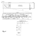
- Figures 4 as taken from G.709 show the frame structure of transport signals in OTN.
- the shown frame contains 3834 columns by 4 rows.
- the transmission of the frame is row by row from left to right.
- Columns 1 to 16 contain overhead.
- Row 1 carries in bytes 1 to 7 the frame argument word and from byte 8 to 14 the OTUk overhead.
- OTUk overhead In the OTUk overhead, bytes 8, 9 and 10 are available for section monitoring (SM), where byte 8 is the TTI field of the OTUk.
- SM section monitoring
- Rows 2 to 4 contain the ODUK overhead, where bytes 10, 11, and 12 in row 3 are available for path monitoring (PM). Again, byte 10 in row 3 is the TTI field of the ODUk.
- the one byte TTI carries a 64 byte superframe, i.e. the TTI bytes of 64 subsequent frames form the full TTI field, where the individual bytes are numbered from 0 to 63.
- this 64 bytes TTI superframe bytes 0 to 15 are reserved for a Source Access Point Identifier SAPI, bytes 16 to 31 are reserved for a Destination Access Point identifier DAPI and bytes 32 to 63 are available for operator specific purpose.
- the BIP-8 in the field after the TTI is a byte-interleaved parity of the previous frame and serves for error detection purpose.
- TCM fields Six sublayers of TCM fields are available upon configuration and activation between a TCM source and a TCM sink along a path represented by the ODUk.
- the six TCM fields TCM1-TCM6 are marked with bold lines here and have the same structure and definition as the PM field. Therefore, it is proposed to use the TTI field in one of these six TCM fields, in particular the SAPI field thereof, for the Link Adjacency Discovery (LAD) as defined in G.7714.1.
- LAD Link Adjacency Discovery
- TCM function needs to be configured between TCM source and sink
- one option would be to pre-configure one of the TCM sub-layers as the default TCM for LAD.
- OXC 21 would use then the TTI of the default TCM sublayer for exchanging the LAD messages defined In G7714.1 and OXC 22 would monitor that default sub-layer for LAD messages.
- this pre-configured sublayer is already in use on the particular ODUk path by a preceding node and hence cannot be interrupted with the LAD. It would therefore be advantageous, to monitor in OXC 21 the intended TCM sub-layer first using a non-intrusive TCM monitor and use it only when it shows to be unused. Such technique is described in more detail in EP 1372288 , which is incorporated by reference herein. OXC 22 would then monitor or "scan" all TCM sub-layers for the LAD messages. A default sequence could be defined, in which order the TCM sublayers shall be tried.
- the TTI provides a mechanism to pass a message that is 1 6 bytes in length.
- Each trace byte consists of a message start bit, and 7-bits for "payload".
- the message start bit is set for the first byte in the message, and clear for all remaining bytes in the message.
- the initiating discovery agent sends to the responding discovery agent its discovery agent ID and a TCP-ID.
- This information can be contained directly in the message or can be derived from the message by an external process such as a name-server.
- Discovery messages can contain a TCP Name, which can be uniquely resolved through a name server into the Discovery Agent Data Communication Network (DCN) Address and TCP-ID. It can also contain a DA DCN Address with the actual Discovery Agent ID and TCP-ID values.
- the Discovery Agent ID consists of a DCN Context ID as well as the DCN Address of the sending Discovery Agent.
- the remainder of the message contains an TCP-ID, which has local significance to the Discovery Agent transmitting the Discovery Message.
- the discovery messages can carry a DA DCN Name, which contains the Discovery Agent ID and the TCP-ID value.
- the Discovery Agent ID is in the form of a DCN Name. Consequently, a name-server must be used to translate the DCN Name into the DCN Address of the Discovery Agent.
- the response message can be transmitted for instance using a control plane protocol through the control plane to the DA address provided in the discovery message. It can alternatively be transmitted in reverse direction using the same TCM TTI field.
- the Discovery Agent When the Discovery Agent receives the discovery message for the first time, it may notify the originating Discovery Agent that the message was received on a trail termination associated with a particular TCP.
- This TCP called the Discovery Sync TCP, is identified in the response using the discovery information currently being sent on the TCP. Additional optional attributes may be included as a part of an implementation as defined by G.7714.1.
- TCP-link connection endpoints Once a bidirectional link has been discovered, it should be checked against management-provided pol icy to determine if correct TCP-link connection endpoints have been correctly connected. If the policy states that the TCP-link connection endpoints may not be paired to form a link, then a misconnection condition exists.
- program storage devices e.g., digital data storage media, which are machine or computer readable and encode machine-executable or computer-executable programs of instructions, wherein said instructions perform some or all of the steps of said above-described methods.
- the program storage devices may be, e.g., digital memories, magnetic storage media such as a magnetic disks and magnetic tapes, hard drives, or optically readable digital data storage media.
- the embodiments are also intended to cover computers programmed to perform said steps of the above-described methods.
Landscapes
- Engineering & Computer Science (AREA)
- Computer Networks & Wireless Communication (AREA)
- Signal Processing (AREA)
- Data Exchanges In Wide-Area Networks (AREA)
Abstract
Description
- The present invention relates to the field of telecommunications and more particularly to a method and related apparatus for automatic discovery in on optical transport network.
- The Optical Transport Network (OTN) is a network te-chnology for the transport of optical data signals at very high rates (2,5, 10, and 40 Grit/s) OTN relies on time division multiplexing of constant rate transport signals to even higher rate transport signals and supports wavelength division multiplexing, as well. Signal structures and interfaces of the Optical Transport Network have been defined in ITU-T G.709 (03/2003), which is incorporated by reference herein.
- Control plane technologies based on the GMPLS protocol family have been introduced to allow automated path setup through the network. Traditionally, creating traffic paths through a series of network elements has involved configuration of individual cross-connections on each network element. In an Automatic Switched (Optical) Transport Network (ASTN or ASON), just the start point, end point and bandwidth required needs to be specified through the user, and the control plane of the network will automatically allocate the path through the network, provision the traffic path, set up cross-connections, and allocate bandwidth from the paths for a client signal.
- In order to support such automatic path creation through control plane signaling, a protocol for automatic discovery of layer adjacencies in the transport plane has been defined in ITU-T G.7714.1(04/3003), which is incorporated by reference herein. Layer Adjacency Discovery (LAD) describes the process of discovering the link connection end-point relationships and verifying their connectivity. The term "discovery" is used in this context to refer to both "discovery" and verification. G.7714.1 defines two alternative methods: one using a test set in the client layer, the other using in-band overhead in the server layer.
- In particular, G.7714.1 defines under its
chapter 6 the following mechanisms as applicable to the OTN layer networks: - OTUk layer: Within the OTUK layer the SM section monitoring byte and the GCC0 may be used to support discovery of the OTUk adjacency. Specifically, the SAPI subfield within the SM is used to carry the discovery message.
- ODUk layer: Within the ODUk layer the PM path monitoring byte and the GCC1 and GCC2 bytes may be used to support discovery of the OOUk adjacency. Specifically, the SAPI subfield within the PM is used to carry the discovery message.
- The present invention aims at improving this automatic discovery mechanism.
- The inventor has discovered two main problems, which arise with the layer adjacency discovery as defined in G.7714.1: the first method defined there uses the an overhead field, in particular the section monitoring byte, which is also termed Trail Trace Identifier (TTI), in the overhead of the transport frames at the server layer, which are termed Optical Transport Units (OTUs). A problem exists when the connection between two optical cross-connects, which have to communicate in the discovery process with each other, leads over a WDM spon and the OTU overhead is terminated at intermediate WDM equipment In this case, two optical cross-connects cannot use the OTU layer for LAD. Alternatively in accordance with G7714.1, the layer adjacency discovery can use the TTI field in the overhead of a higher multiplexing layer, i.e. an Optical Dota Unit-k (ODUk) transported as client layer signal within the server layer OTU frames. This however requires the presence of an ODUK trail termination function, which is not always available. Hence, the applicability of trail-trace-bosed link adjacency discovery in the OTN is limited.
- The inventor proposes a solution to this problem that utilizes a Tandem Connection Monitoring (TCM) sublayer for auto-discovery.
- In particular a method and rented network nodes are provided for discovering link adjacency in an Optical Transport Network. A first network node has a first discovery agent and a second network node has a second discovery agent. A discovery message is transmitted from a first interface of the first network node over one or more subsequent network links to a second interface of the second network node. The discovery message contains Information indicative of an discovery agent identifier associated with the first discovery agent and of a termination connection point identifier associated with the first interface. In order to transmit the discovery message, the first interface is configured to perform a tandem connection source function using a reserved field in an overhead portion of signal frames to be transmitted. The second interface is configured to perform a Tandem Connection Monitoring function on the same reserved field of received signal frames. The discovery message is sent using a Trail Trace Identifier byte available in the reserved field.
- Preferred embodiments of the present invention will now be described with reference to the accompanying drawings in which
- figure 1
- shows an example of layer adjacency discovery using the currency defined OTUk TTI;
- figure 2
- shows layer adjacency discovery making use of a TGM sublayer between two optical cross-connects interconnected over intermediate WDM equipment;
- figure 3
- shows an abstraction of
figure 2 ; and - figure 4
- shows the frame structure used in OTN.
- in SQNET/SDH networks, regenerators have mostly disappeared, which means that SONET/SDH cross-connects are directly interconnected without regenerators terminating the Regenerator Section Overhead (RS-OH). Based on this, it is possible to utilize the in-seiwice J0 sediontrace-bosed LAD as defined in G.7714.1
- Looking at the OTN, the OTU layer is the layer that corresponds to the section layers (MS/RS) in SONET/SDH. The OTN as defined in G.709, comprises digital (electrical) as well as photonic layers, The OTU layer is the lowest digital (electrical) layer in the OTN hierarchy and "provides for the transport of ODU client signals through an OTU trail between 3R points of the OTN". If two OTN cross-connects are interconnected via a (single-hop) OTU trail as depicted in
figure 1 , in-service OTU-TTI based LAD can be applied and the corresponding OTU Connection Points (CPs) can be inferred as defined in G.7714.1. - A basic network element in a transport network is referred to as a cross-connect, which provides electrical and/or optical switching operations to establish interconnections through the network.
Figure 1 shows afirst OTN cross-connect 11 connected over a bidirectionaloptical link 13 to asecond OTN cross-conned 12. Cross-connect 11 has afirst interface 111 with an associatedOTUk termination function 112 and asecond interface 113 and associatedOTUK termination function 114. Aswitch matrix 115interconnects interfaces A discovery agent 116, which runs on a controller of theOTN cross-connect 11, configuresOTUK termination function 112 to insertappropriate discovery messages 14 into the TTI field of the OTUk overhead andanalyses discovery messages 14 received in reverse direction in the TTI field from OTN eross-connect 12. Equally, OTNcross-connect 12hats interfaces switch matrix 125 interconnecting theinterfaces discovery agent 126, which controlsOTU termination functions - Alternatively, the higher order (HO) ODU CPs can also be inferred because of the fixed 1:1 relationship between the OTU CP and the HO ODU CP as there is matrix or switching function between the OTU and the HO ODU layer.
- In today's OTNs, the photonic functions are typically decoupled from the electrical functions and the related functions are located in different types of equipment. This means that an OTN is typically composed of OTN cross-connects that mainly provide electrical switching functions for the various ODU layers and WDM equipment that mainly provides the photonic transmission and switching functions such as transponders, wavelength multiplexers/demultiplexers and wavelength selective switches and may in addition have an electrical HO ODU switching function, Based on this functional split, an OTN cross connect is typically interconnected with its peers over WDM links or a WDM network and the interconnection between the OTN cross-connect and the adjacent WDM device is realized via an OTU trail. This means even in the simplest case where only two WDM devices interconnect two OTN cross-connects over a single WDM link, three OTU trails have to be crossed: one between the OTN cross-connect (OXC) and the transponder in the near end WDM device, one between the two transponders in the two WDM devices, and another one between the transponder in the far end WDM device and the for end OXC. This situation is schematically depicted in
figure 2 . - That situation has some implications for link adjacency discovery (LAD) in an OTN. Due to the termination of the OTU layer in the WDM equipment, the two OTN cross-connects cannot use the OTU layer for LAD and would have to go to the next higher layer in the OTN hierarchy, i.e., the higher order (HO) ODU layer.
- However, only if the HO ODU layer is terminated at the two adjacent ODU-cross-connects, i.e. the HO ODU layer is only used as multiplexing layer for LO ODU connections between two adjacent OTN cross-confiects, the TTI-based LAD can be applied of the HOOD layer. In other cases, when for example the HO ODU layer is not terminated, in-service TTI-based LAD cannot be applied. This means that HO ODU layer TTI-based LAD. can be applied in some situations and must not be applied in some other situations. Hence, a solution would be desirable that can always be applied.
- In the discussion below, a solution based on the HO ODU Tandem Connection Monitoring (TCM) function is described that solves the LAD issues described above.
-
Figure 2 illustrates a scenario where two OTN cross-connects (OXCs) 21, 22 are interconnected vio a WDM network,OXC 21 has two interfaces for optical transport signals. Each interfaces has aOTUk termination function termination function ODUkT switch matrix 215 interconnects the interfaces at ODUk level. Adiscovery agent 216 configures the ODUkT termination function. Equally,OXC 22 had interfaces withOTUK termination function 222, 224 andODUkT termination function switch matrix 225 interconnecting the interfaces at ODUk level and adiscovery agent 226 configuring the ODUkT termination functions. - In terms of hardware, the termination functions are typically performed by an overhead processor available on the line card of the OXC. Alternatively, overhead termination functions could be implemented on a common overhead server, which is interconnected with the various line cards via the switching matrix or via a dedicated bus architecture. The discovery agent would typically be a software implemented process running on a controller of the respective network node, but can also be implemented as a dedicated controller. While only two interfaces are shown in the figures, it should be clear that real network nodes have a large number of these interfaces. The switch matrix would typically perform a space and time switching function.
-
OXC 21 is connected over anoptical link 25 to afirst WDM node 23. OverWDM link 27,WDM node 23 is connected toWDM node 24, which in turn is connected via anoptical link 26 toOXC 22. -
WDM node 23 has at its input anOTUk termination function 232 for the signal received fromOXC 21 and at its output towards WDM node 24 a series of termination functions, in particular, anOTUK termination function 234, an Optical Channel (OCh)termination function 235, anOCh connection function 236, an optical Multiplex Section (OMS)termination function 237 and an Optical Transmission Section (OTS) termination function. The same termination functions 242-548 are present inWDM node 24, as well, These functions are known as such and are defined and explained in detail in G.709, so that no further discussion is necessary here. - The critical aspect however is that
WMD nodes transponder OXCs Figure 3 therefore shows an abstraction offigure 2 in the sense thatWDM nodes complex WDM subnetwork 30, where the connection betweenOXC 21 andOXC 22 can lead over multiple OTUk trails. The consequence is that the OTUk layer is not available for the link adjacency discovery (LAD) betweenOXC 21 andOXC 22. - The other option as specified in G.7714.1 is to perform LAD at the ODUk layer network and to use the ODUk TTI for carrying the discovery message. As already discussed above, the HO ODU trail termination function may not be present for example as shown in
figures 2 and3 , since ODUk needs to be connected inOXC 21 andOXC 22 transparently. In particular, the HO ODU signal represents the service layer and the ODUk CP is connected to another ODUk CP on a different port of the same OXC. Hence, the ODUk layer TTI cannot be used for LAD. - Therefore, as shown in
figures 2 and3 , it is proposed to add Tandem Connection Monitoring (TCM) Source and Sink functions 217, 227 innetwork nodes - G.709 defines six TCM sub-layers that may exist underneath the HO ODUk layer network. The proposal is now to establish a tandem connection, using one out of the six TCM sub-layers, and to use the TTI fields of the TCM function for LAD as defined in G.7714.1, The TCM termination functions
ODUkT discovery message discovery messages - The proposed HO ODUkT TTI-based LAD allows to discover the HO ODU CPs while the ODUk signal including its own TTI is in-service. This method can also be applied when the HO ODU signal is terminated and carries LO ODU signals that are interconnected or can be terminated in the OXC.
-
Figures 4 as taken from G.709 show the frame structure of transport signals in OTN. The shown frame contains 3834 columns by 4 rows. The transmission of the frame is row by row from left to right. Columns 1 to 16 contain overhead. Row 1 carries in bytes 1 to 7 the frame argument word and from byte 8 to 14 the OTUk overhead. In the OTUk overhead,bytes -
Rows 2 to 4 contain the ODUK overhead, wherebytes row 3 are available for path monitoring (PM). Again,byte 10 inrow 3 is the TTI field of the ODUk. - The one byte TTI carries a 64 byte superframe, i.e. the TTI bytes of 64 subsequent frames form the full TTI field, where the individual bytes are numbered from 0 to 63. In this 64 bytes TTI superframe, bytes 0 to 15 are reserved for a Source Access Point Identifier SAPI,
bytes 16 to 31 are reserved for a Destination Access Point identifier DAPI andbytes 32 to 63 are available for operator specific purpose. The BIP-8 in the field after the TTI is a byte-interleaved parity of the previous frame and serves for error detection purpose. - Instead of the SM or PM field in the OTUk or ODUk overhead, respectively, it is proposed to use one of the TCM fields, Six sublayers of TCM fields are available upon configuration and activation between a TCM source and a TCM sink along a path represented by the ODUk. The six TCM fields TCM1-TCM6 are marked with bold lines here and have the same structure and definition as the PM field. Therefore, it is proposed to use the TTI field in one of these six TCM fields, in particular the SAPI field thereof, for the Link Adjacency Discovery (LAD) as defined in G.7714.1.
- Since the TCM function needs to be configured between TCM source and sink, one option would be to pre-configure one of the TCM sub-layers as the default TCM for LAD. For example:
OXC 21 would use then the TTI of the default TCM sublayer for exchanging the LAD messages defined In G7714.1 andOXC 22 would monitor that default sub-layer for LAD messages. - However, there may also be the situation that this pre-configured sublayer is already in use on the particular ODUk path by a preceding node and hence cannot be interrupted with the LAD. It would therefore be advantageous, to monitor in
OXC 21 the intended TCM sub-layer first using a non-intrusive TCM monitor and use it only when it shows to be unused. Such technique is described in more detail inEP 1372288 , which is incorporated by reference herein.OXC 22 would then monitor or "scan" all TCM sub-layers for the LAD messages. A default sequence could be defined, in which order the TCM sublayers shall be tried. - The TTI provides a mechanism to pass a message that is 1 6 bytes in length. Each trace byte consists of a message start bit, and 7-bits for "payload". The message start bit is set for the first byte in the message, and clear for all remaining bytes in the message.
- The following Attributes will be used in the LAD according to G.7714.1:
- Distinguishing Character
This character "+" is used as the distinguishing character, and its purpose is to avoid the format of OTN trail-trace string being confused with some other optional format. - Discovery Agent (DA) Identifier (ID)
The DA ID must be unique within the context of the link being discovered. Two different representations of the DA ID exist: a DA Address and a DA Name. - Discovery Agent Address
Two attributes are defined to support the DA Address:- o DON (Data Communication Network) Context ID This represents an assigned number (a globally assigned number would be desirable). This attribute may be used in conjunction with the DCN Address attribute to guarantee uniqueness for the DA ID. If the sending and receiving Discovery Agents at each end of the link are within different DCN Contexts, but use the same DCN
Addresses, they may be unable to communicate. - o DA DCN Address
This represents the address used to identify the Discovery Agent.
- o DON (Data Communication Network) Context ID This represents an assigned number (a globally assigned number would be desirable). This attribute may be used in conjunction with the DCN Address attribute to guarantee uniqueness for the DA ID. If the sending and receiving Discovery Agents at each end of the link are within different DCN Contexts, but use the same DCN
- Discovery Agent Name
This is a name that can be resolved into a DA Address. - TCP-ID
The TCP-ID contains the identifier for the TCP (Termination Connection Point) being discovered. This has only local significance within the scope of the DA. - During the LAD, the initiating discovery agent sends to the responding discovery agent its discovery agent ID and a TCP-ID. This information can be contained directly in the message or can be derived from the message by an external process such as a name-server. Discovery messages can contain a TCP Name, which can be uniquely resolved through a name server into the Discovery Agent Data Communication Network (DCN) Address and TCP-ID. It can also contain a DA DCN Address with the actual Discovery Agent ID and TCP-ID values. The Discovery Agent ID consists of a DCN Context ID as well as the DCN Address of the sending Discovery Agent. The remainder of the message contains an TCP-ID, which has local significance to the Discovery Agent transmitting the Discovery Message. In a third variant, the discovery messages can carry a DA DCN Name, which contains the Discovery Agent ID and the TCP-ID value. However, unlike the DCN Address format, the Discovery Agent ID is in the form of a DCN Name. Consequently, a name-server must be used to translate the DCN Name into the DCN Address of the Discovery Agent.
- The procedure for Layer Adjacency Discovery is as follows:
- 1. The initiating Discovery Agent transmits the discovery message with the appropriate attributes.
- 2. Upon receiving a discovery message, the responding DA checks to determine the applicability of the message using the distinguishing character to validate the discovery message.
- 3. After determining that the received message is a discovery message, the responding Discovery Agent then determines whether the values received are unique with respect to already discovered neighbours.
- 3.1. If the Format ID = 1, a name server is needed to determine the DA DCN address and TCP-ID.
- 3.2. If the Format ID = 2, then no further address translation is needed. 3.3. If the Format ID = 3, then address translation is needed for the DA DCN name.
- 4. Generate a discovery response message.
- The response message can be transmitted for instance using a control plane protocol through the control plane to the DA address provided in the discovery message. It can alternatively be transmitted in reverse direction using the same TCM TTI field.
- When the Discovery Agent receives the discovery message for the first time, it may notify the originating Discovery Agent that the message was received on a trail termination associated with a particular TCP. This TCP, called the Discovery Sync TCP, is identified in the response using the discovery information currently being sent on the TCP. Additional optional attributes may be included as a part of an implementation as defined by G.7714.1.
- Once a Discovery Message has been received on a resource and a Discovery Response Message describing the some resource is received over the DCN, it is possible to correlate the messages and determine if a bidirectional link exists. If the TCP-ID corresponding to the remote endpoint of the link connection is not the same in both messages, then a miswired condition exists. If the TCP-ID is the some then the Transmit/Receive signal pair have been properly wired. This is described in greater detail in Appendix II of G.7714.1.
- Once a bidirectional link has been discovered, it should be checked against management-provided pol icy to determine if correct TCP-link connection endpoints have been correctly connected. If the policy states that the TCP-link connection endpoints may not be paired to form a link, then a misconnection condition exists.
- A person of skill in the art would readily recognize that steps of various above-described methods can be performed by programmed computers. Herein, some embodiments are also intended to cover program storage devices, e.g., digital data storage media, which are machine or computer readable and encode machine-executable or computer-executable programs of instructions, wherein said instructions perform some or all of the steps of said above-described methods. The program storage devices may be, e.g., digital memories, magnetic storage media such as a magnetic disks and magnetic tapes, hard drives, or optically readable digital data storage media. The embodiments are also intended to cover computers programmed to perform said steps of the above-described methods.
- The description and drawings merely illustrate the principles of the invention. It will thus be appreciated that those skilled in the art will be able to devise various arrangements that, although not explicitly described or shown herein, embody the principles of the invention and are included within its spirit and scope. Furthermore, all examples recited herein are principally intended expressly to be only for pedagogical purposes to aid the reader in understanding the principles of the invention and the concepts contributed by the inventor(s) to furthering the art, and are to be construed as being without limitation to such specifically recited examples and conditions. Moreover, all statements herein reciting principles, aspects, and embodiments of the invention, as well as specific examples thereof, are intended to encompass equivalents thereof.
Claims (7)
- A method of discovering link adjacency in an Optical Transport Network between a first network node (21) having a first discovery agent (216) and a second network node (22) having a second discovery agent (226); the method comprising transmitting a discovery message (210) from a first interface of the first network node (22) over one or more subsequent network links (25, 26, 27) of said Optical Transport Network to a second interface of the second network node (22), said discovery message (210) comprising information indicative of an discovery agent identifier associated with the first discovery agent (216) and of a termination connection point identifier associated with the first interface;
said method further comprising:- configuring the first interface to perform a tandem connection source function (217) using a reserved field (TCM1-TCM6) in an overhead portion of signal frames to be transmitted- configuring said second interface to perform a Tandem Connection Monitoring function (227) on the same reserved field (TCM1-TCM6) of received signal frames; and- using a Trail Trace Identifier (TTI) byte available in said reserved field (TCM1-TCM6) to transmit said discovery message (210). - A method according to claim 1, wherein said first discovery agent (216) configures said first interface to perform said tandem connection source function on a predetermined one out of six available fields (TCM1 -TCM6) provided in said overhead for Tandem Connection Monitoring.
- A method according to claim 1, wherein said first discovery agent (216) configures said first interface to monitor said reserved field prior to activating said Tandem Connection Source function (217) for the presence of a Tandem Connection Monitoring signal already existing in said field and if so, uses another of said six available fields (TCM1-TCM6) provided in said overhead for Tandem Connection Monitoring.
- A method according to claim 1, wherein said second discovery agent (226) configures said second interface to perform said Tandem Connection Monitoring function (227) on a predetermined one out of six available fields (TCM1-TCM6) provided in said overhead for Tandem Connection Monitoring.
- A method according to claim 1, wherein said second discovery agent (226) configures said second interface to monitor all six fields (TCM1-TCM6) provided in said overhead for Tandem Connection Monitoring for the presence of said discovery message,
- A first network node (21) for use in an Optical Transport Network comprising: a discovery agent (216) for discovering link adjacency in said Optical Transport Network, and at least one interface connected to said Optical Transport Network; wherein said discovery agent (216) is adapted to configure the interface to perform a tandem connection source function (217) using a reserved field (TCM1-TCM6) in an overhead portion of signal frames to be transmitted and to transmit a discovery message (210) to an adjacent second network node (22) using a Trail Trace Identifier (TTI) available in said reserved field (TCM1-TCM6), said discovery message (210) comprising information indicative of a discovery agent identifier associated with the discovery agent (216) and of a termination connection point identifier associated with the interface.
- A second network node (22) for use in an Optical Transport Network comprising: a discovery agent (226) for discovering link adjacency in said Optical Transport Network, and at least one interface connected to said Optical Transport Network; wherein said discovery agent (226) is adapted to configure the interface to perform a tandem connection monitoring function (227) using a reserved field (TCM1-TCM6) in an overhead portion of received signal frames and to receive a discovery message (210) from an adjacent first network node (21) within a Trail Trace Identifier (TTI) available in said reserved field (TCM1-TCM6), said discovery message (210) comprising information indicative of a discovery agent identifier associated with a discovery agent (216) of said first network node (21) and of a termination connection point identifier associated with an interface of said first network node (21).
Priority Applications (8)
| Application Number | Priority Date | Filing Date | Title |
|---|---|---|---|
| EP09305838A EP2296300B1 (en) | 2009-09-14 | 2009-09-14 | Method and apparatus for automatic discovery in optical transport networks |
| AT09305838T ATE556507T1 (en) | 2009-09-14 | 2009-09-14 | METHOD AND DEVICE FOR AUTOMATIC DETECTION IN OPTICAL TRANSPORT NETWORKS |
| ES09305838T ES2383938T3 (en) | 2009-09-14 | 2009-09-14 | Procedure and apparatus for automatic detection in optical transport networks |
| US13/394,897 US9203540B2 (en) | 2009-09-14 | 2010-08-13 | Method and apparatus for automatic discovery in optical transport networks |
| KR1020127009369A KR101342429B1 (en) | 2009-09-14 | 2010-08-13 | Method and apparatus for automatic discovery in optical transport networks |
| PCT/EP2010/061853 WO2011029695A1 (en) | 2009-09-14 | 2010-08-13 | Method and apparatus for automatic discovery in optical transport networks |
| CN201080040819.0A CN102498683B (en) | 2009-09-14 | 2010-08-13 | Method and apparatus for automatic discovery in optical transport networks |
| JP2012528297A JP5506931B2 (en) | 2009-09-14 | 2010-08-13 | Method and apparatus for automatic discovery in an optical transport network |
Applications Claiming Priority (1)
| Application Number | Priority Date | Filing Date | Title |
|---|---|---|---|
| EP09305838A EP2296300B1 (en) | 2009-09-14 | 2009-09-14 | Method and apparatus for automatic discovery in optical transport networks |
Publications (2)
| Publication Number | Publication Date |
|---|---|
| EP2296300A1 true EP2296300A1 (en) | 2011-03-16 |
| EP2296300B1 EP2296300B1 (en) | 2012-05-02 |
Family
ID=41571839
Family Applications (1)
| Application Number | Title | Priority Date | Filing Date |
|---|---|---|---|
| EP09305838A Not-in-force EP2296300B1 (en) | 2009-09-14 | 2009-09-14 | Method and apparatus for automatic discovery in optical transport networks |
Country Status (8)
| Country | Link |
|---|---|
| US (1) | US9203540B2 (en) |
| EP (1) | EP2296300B1 (en) |
| JP (1) | JP5506931B2 (en) |
| KR (1) | KR101342429B1 (en) |
| CN (1) | CN102498683B (en) |
| AT (1) | ATE556507T1 (en) |
| ES (1) | ES2383938T3 (en) |
| WO (1) | WO2011029695A1 (en) |
Cited By (3)
| Publication number | Priority date | Publication date | Assignee | Title |
|---|---|---|---|---|
| EP3054606A4 (en) * | 2013-12-30 | 2016-11-09 | Huawei Tech Co Ltd | REROUTING METHOD AND AUTOMATICALLY SWITCHABLE OPTICAL NETWORK |
| EP3422611A1 (en) * | 2017-06-30 | 2019-01-02 | Alcatel Submarine Networks | Automatic paths discovery in an optical network |
| CN115884013A (en) * | 2022-11-18 | 2023-03-31 | 华信塞姆(成都)科技有限公司 | Method for automatically discovering SDH optical network topology |
Families Citing this family (8)
| Publication number | Priority date | Publication date | Assignee | Title |
|---|---|---|---|---|
| US8417111B2 (en) * | 2010-10-28 | 2013-04-09 | Ciena Corporation | Optical network in-band control plane signaling, virtualized channels, and tandem connection monitoring systems and methods |
| US20120246297A1 (en) * | 2011-03-25 | 2012-09-27 | Vijaya Shanker | Agent based monitoring for saas it service management |
| CN103269277B (en) * | 2013-04-22 | 2016-06-08 | 华为技术有限公司 | For finding method and system, the first network element and the webmaster equipment of link |
| IN2014DE00528A (en) * | 2014-02-25 | 2015-08-28 | Ciena Corp | |
| KR102045866B1 (en) * | 2015-01-30 | 2019-11-18 | 한국전자통신연구원 | Method and apparatus for gathering and constructing network topology and service path information in optical transport networks |
| CN107547124B (en) * | 2016-06-24 | 2021-06-15 | 中兴通讯股份有限公司 | Reset control method and device |
| CN112533082B (en) * | 2019-09-17 | 2023-11-21 | 中国移动通信有限公司研究院 | Link resource discovery method, device, equipment and computer-readable storage medium |
| CN115955618A (en) * | 2022-11-01 | 2023-04-11 | 中电信数智科技有限公司 | Method and system for network topology realization and dynamic update based on access OTN equipment |
Citations (3)
| Publication number | Priority date | Publication date | Assignee | Title |
|---|---|---|---|---|
| EP1372288A1 (en) | 2002-06-12 | 2003-12-17 | Alcatel | Tandem connection activation/deactivation |
| EP1916799A1 (en) * | 2006-02-07 | 2008-04-30 | Huawei Technologies Co., Ltd. | A method for implementing tandem concatenation monitoring automatically and apparatus thereof |
| EP2075955A1 (en) * | 2006-09-27 | 2009-07-01 | Huawei Technologies Co Ltd | A method and apparatus for monitoring network quality |
Family Cites Families (14)
| Publication number | Priority date | Publication date | Assignee | Title |
|---|---|---|---|---|
| EP1229692A1 (en) * | 2001-02-02 | 2002-08-07 | BRITISH TELECOMMUNICATIONS public limited company | Method and apparatus for tunnelling data in a network |
| ITMI20010900A1 (en) | 2001-04-30 | 2002-10-30 | Marconi Comm Spa | TELECOMMUNICATIONS NETWORK WITH AUTOMATIC TOPOLOGY DETECTION AND METHOD FOR THIS DETECTION |
| US7747165B2 (en) * | 2001-06-13 | 2010-06-29 | Alcatel-Lucent Usa Inc. | Network operating system with topology autodiscovery |
| JP2003188919A (en) * | 2001-12-19 | 2003-07-04 | Nec Corp | Network, switch device, method for processing otn frame to be used therefor, its circuit and integrated circuit |
| US7983182B2 (en) * | 2002-02-01 | 2011-07-19 | Tellabs Operations, Inc. | Methods and apparatus for exchanging network connectivity and capability information |
| EP1422968B1 (en) * | 2002-11-19 | 2010-01-13 | Alcatel Lucent | Failure localization in a transmission network |
| EP1463370B1 (en) * | 2003-03-28 | 2008-03-05 | Alcatel Lucent | Transport network restoration method |
| CN1269320C (en) * | 2003-07-24 | 2006-08-09 | 烽火通信科技股份有限公司 | Organizing method for automaitic switching optical network node communication structure based on embedded communication channel technique |
| CN100596043C (en) * | 2004-08-26 | 2010-03-24 | 华为技术有限公司 | Method and device for realizing transparent transmission of low-speed signals in optical transmission network |
| US9172489B2 (en) | 2005-06-30 | 2015-10-27 | Infinera Corporation | Discovery of an adjacent network element within a network data plane |
| JP2007096499A (en) | 2005-09-27 | 2007-04-12 | Fujitsu Ltd | Optical receiver and dispersion compensation method in optical receiver |
| EP1780942A1 (en) * | 2005-10-25 | 2007-05-02 | Alcatel Lucent | Method for automatically discovering a bus system in a multipoint transport network, multipoint transport network and network node |
| US7633952B2 (en) * | 2006-02-27 | 2009-12-15 | Ciena Corporation | Discovery of physically adjacent neighbor devices using a unidirectional in-band process coupled with an out-of-band follow-up process |
| CN101145839A (en) * | 2006-09-11 | 2008-03-19 | 华为技术有限公司 | Method and device for realizing k-order optical channel data unit sublayer monitoring subnetwork connection protection |
-
2009
- 2009-09-14 AT AT09305838T patent/ATE556507T1/en active
- 2009-09-14 EP EP09305838A patent/EP2296300B1/en not_active Not-in-force
- 2009-09-14 ES ES09305838T patent/ES2383938T3/en active Active
-
2010
- 2010-08-13 JP JP2012528297A patent/JP5506931B2/en not_active Expired - Fee Related
- 2010-08-13 KR KR1020127009369A patent/KR101342429B1/en not_active Expired - Fee Related
- 2010-08-13 US US13/394,897 patent/US9203540B2/en not_active Expired - Fee Related
- 2010-08-13 WO PCT/EP2010/061853 patent/WO2011029695A1/en not_active Ceased
- 2010-08-13 CN CN201080040819.0A patent/CN102498683B/en not_active Expired - Fee Related
Patent Citations (3)
| Publication number | Priority date | Publication date | Assignee | Title |
|---|---|---|---|---|
| EP1372288A1 (en) | 2002-06-12 | 2003-12-17 | Alcatel | Tandem connection activation/deactivation |
| EP1916799A1 (en) * | 2006-02-07 | 2008-04-30 | Huawei Technologies Co., Ltd. | A method for implementing tandem concatenation monitoring automatically and apparatus thereof |
| EP2075955A1 (en) * | 2006-09-27 | 2009-07-01 | Huawei Technologies Co Ltd | A method and apparatus for monitoring network quality |
Cited By (3)
| Publication number | Priority date | Publication date | Assignee | Title |
|---|---|---|---|---|
| EP3054606A4 (en) * | 2013-12-30 | 2016-11-09 | Huawei Tech Co Ltd | REROUTING METHOD AND AUTOMATICALLY SWITCHABLE OPTICAL NETWORK |
| EP3422611A1 (en) * | 2017-06-30 | 2019-01-02 | Alcatel Submarine Networks | Automatic paths discovery in an optical network |
| CN115884013A (en) * | 2022-11-18 | 2023-03-31 | 华信塞姆(成都)科技有限公司 | Method for automatically discovering SDH optical network topology |
Also Published As
| Publication number | Publication date |
|---|---|
| CN102498683A (en) | 2012-06-13 |
| KR101342429B1 (en) | 2013-12-18 |
| JP5506931B2 (en) | 2014-05-28 |
| ES2383938T3 (en) | 2012-06-27 |
| JP2013504910A (en) | 2013-02-07 |
| US20120177364A1 (en) | 2012-07-12 |
| WO2011029695A1 (en) | 2011-03-17 |
| EP2296300B1 (en) | 2012-05-02 |
| ATE556507T1 (en) | 2012-05-15 |
| US9203540B2 (en) | 2015-12-01 |
| KR20120068906A (en) | 2012-06-27 |
| CN102498683B (en) | 2014-10-29 |
Similar Documents
| Publication | Publication Date | Title |
|---|---|---|
| EP2296300B1 (en) | Method and apparatus for automatic discovery in optical transport networks | |
| US11695472B2 (en) | Partial survivability for multi-carrier and multi-module optical interfaces | |
| US10826604B2 (en) | Fault localization using tandem connection monitors in optical transport network | |
| US9882634B1 (en) | Coordinated connection validation systems and methods among mated transceivers for verifying optical and data plane connectivity | |
| US8971706B2 (en) | Link discovery, verification, and failure isolation in an optical communication system | |
| Maeda | Management and control of transparent optical networks | |
| CN101453667B (en) | digital cross connect | |
| US9853722B1 (en) | Systems and methods for path protection switching due to client protection switching | |
| JP5883509B2 (en) | Network elements for switching time division multiplexed signals | |
| US20020176131A1 (en) | Protection switching for an optical network, and methods and apparatus therefor | |
| ES2541137T3 (en) | Method for performing subnet connection protection with sublayer monitoring of an optical channel data unit of range k and apparatus for doing so | |
| JP2005521330A (en) | Supervisory channel in optical network systems | |
| US10587500B2 (en) | Intelligent optical restoration in integrated multi-layer networks | |
| US20060221865A1 (en) | Method and system for autonomous link discovery and network management connectivity of remote access devices | |
| US7688717B2 (en) | Transport network restoration method supporting extra traffic | |
| EP2075955A1 (en) | A method and apparatus for monitoring network quality | |
| EP1557980A1 (en) | Fast rerouting of traffic in a circuit switched mesh network | |
| US7412165B1 (en) | DCC loop plug | |
| US20090297141A1 (en) | Transmission apparatus, path testing method, and storage medium | |
| KR101507123B1 (en) | Method and Apparatus for Creating Resize Control Overhead in Optical Transport Network | |
| US11101882B1 (en) | Low order regenerator with high order traffic conditioning in optical transport network | |
| EP2874337A1 (en) | Method for operating an optical transport network node | |
| US20260031903A1 (en) | Communication system and normalcy judgment method |
Legal Events
| Date | Code | Title | Description |
|---|---|---|---|
| PUAI | Public reference made under article 153(3) epc to a published international application that has entered the european phase |
Free format text: ORIGINAL CODE: 0009012 |
|
| 17P | Request for examination filed |
Effective date: 20100226 |
|
| AK | Designated contracting states |
Kind code of ref document: A1 Designated state(s): AT BE BG CH CY CZ DE DK EE ES FI FR GB GR HR HU IE IS IT LI LT LU LV MC MK MT NL NO PL PT RO SE SI SK SM TR |
|
| AX | Request for extension of the european patent |
Extension state: AL BA RS |
|
| RIC1 | Information provided on ipc code assigned before grant |
Ipc: H04L 12/26 20060101ALI20110329BHEP Ipc: H04J 3/14 20060101AFI20110329BHEP Ipc: H04J 3/16 20060101ALI20110329BHEP |
|
| REG | Reference to a national code |
Ref country code: DE Ref legal event code: R079 Ref document number: 602009006750 Country of ref document: DE Free format text: PREVIOUS MAIN CLASS: H04J0003140000 Ipc: H04L0012240000 |
|
| RIC1 | Information provided on ipc code assigned before grant |
Ipc: H04Q 11/00 20060101ALI20111019BHEP Ipc: H04J 3/14 20060101ALI20111019BHEP Ipc: H04L 12/26 20060101ALI20111019BHEP Ipc: H04L 12/24 20060101AFI20111019BHEP Ipc: H04J 3/16 20060101ALI20111019BHEP |
|
| GRAP | Despatch of communication of intention to grant a patent |
Free format text: ORIGINAL CODE: EPIDOSNIGR1 |
|
| RAP1 | Party data changed (applicant data changed or rights of an application transferred) |
Owner name: ALCATEL LUCENT |
|
| GRAS | Grant fee paid |
Free format text: ORIGINAL CODE: EPIDOSNIGR3 |
|
| GRAA | (expected) grant |
Free format text: ORIGINAL CODE: 0009210 |
|
| AK | Designated contracting states |
Kind code of ref document: B1 Designated state(s): AT BE BG CH CY CZ DE DK EE ES FI FR GB GR HR HU IE IS IT LI LT LU LV MC MK MT NL NO PL PT RO SE SI SK SM TR |
|
| REG | Reference to a national code |
Ref country code: GB Ref legal event code: FG4D |
|
| REG | Reference to a national code |
Ref country code: AT Ref legal event code: REF Ref document number: 556507 Country of ref document: AT Kind code of ref document: T Effective date: 20120515 Ref country code: CH Ref legal event code: EP |
|
| REG | Reference to a national code |
Ref country code: IE Ref legal event code: FG4D |
|
| REG | Reference to a national code |
Ref country code: ES Ref legal event code: FG2A Ref document number: 2383938 Country of ref document: ES Kind code of ref document: T3 Effective date: 20120627 |
|
| REG | Reference to a national code |
Ref country code: DE Ref legal event code: R096 Ref document number: 602009006750 Country of ref document: DE Effective date: 20120705 |
|
| REG | Reference to a national code |
Ref country code: NL Ref legal event code: VDEP Effective date: 20120502 |
|
| REG | Reference to a national code |
Ref country code: LT Ref legal event code: MG4D Effective date: 20120502 |
|
| PG25 | Lapsed in a contracting state [announced via postgrant information from national office to epo] |
Ref country code: FI Free format text: LAPSE BECAUSE OF FAILURE TO SUBMIT A TRANSLATION OF THE DESCRIPTION OR TO PAY THE FEE WITHIN THE PRESCRIBED TIME-LIMIT Effective date: 20120502 Ref country code: SE Free format text: LAPSE BECAUSE OF FAILURE TO SUBMIT A TRANSLATION OF THE DESCRIPTION OR TO PAY THE FEE WITHIN THE PRESCRIBED TIME-LIMIT Effective date: 20120502 Ref country code: CY Free format text: LAPSE BECAUSE OF FAILURE TO SUBMIT A TRANSLATION OF THE DESCRIPTION OR TO PAY THE FEE WITHIN THE PRESCRIBED TIME-LIMIT Effective date: 20120502 Ref country code: IS Free format text: LAPSE BECAUSE OF FAILURE TO SUBMIT A TRANSLATION OF THE DESCRIPTION OR TO PAY THE FEE WITHIN THE PRESCRIBED TIME-LIMIT Effective date: 20120902 Ref country code: PL Free format text: LAPSE BECAUSE OF FAILURE TO SUBMIT A TRANSLATION OF THE DESCRIPTION OR TO PAY THE FEE WITHIN THE PRESCRIBED TIME-LIMIT Effective date: 20120502 Ref country code: LT Free format text: LAPSE BECAUSE OF FAILURE TO SUBMIT A TRANSLATION OF THE DESCRIPTION OR TO PAY THE FEE WITHIN THE PRESCRIBED TIME-LIMIT Effective date: 20120502 Ref country code: NO Free format text: LAPSE BECAUSE OF FAILURE TO SUBMIT A TRANSLATION OF THE DESCRIPTION OR TO PAY THE FEE WITHIN THE PRESCRIBED TIME-LIMIT Effective date: 20120802 |
|
| REG | Reference to a national code |
Ref country code: AT Ref legal event code: MK05 Ref document number: 556507 Country of ref document: AT Kind code of ref document: T Effective date: 20120502 |
|
| PG25 | Lapsed in a contracting state [announced via postgrant information from national office to epo] |
Ref country code: GR Free format text: LAPSE BECAUSE OF FAILURE TO SUBMIT A TRANSLATION OF THE DESCRIPTION OR TO PAY THE FEE WITHIN THE PRESCRIBED TIME-LIMIT Effective date: 20120803 Ref country code: HR Free format text: LAPSE BECAUSE OF FAILURE TO SUBMIT A TRANSLATION OF THE DESCRIPTION OR TO PAY THE FEE WITHIN THE PRESCRIBED TIME-LIMIT Effective date: 20120502 Ref country code: SI Free format text: LAPSE BECAUSE OF FAILURE TO SUBMIT A TRANSLATION OF THE DESCRIPTION OR TO PAY THE FEE WITHIN THE PRESCRIBED TIME-LIMIT Effective date: 20120502 Ref country code: LV Free format text: LAPSE BECAUSE OF FAILURE TO SUBMIT A TRANSLATION OF THE DESCRIPTION OR TO PAY THE FEE WITHIN THE PRESCRIBED TIME-LIMIT Effective date: 20120502 Ref country code: PT Free format text: LAPSE BECAUSE OF FAILURE TO SUBMIT A TRANSLATION OF THE DESCRIPTION OR TO PAY THE FEE WITHIN THE PRESCRIBED TIME-LIMIT Effective date: 20120903 |
|
| PG25 | Lapsed in a contracting state [announced via postgrant information from national office to epo] |
Ref country code: BE Free format text: LAPSE BECAUSE OF FAILURE TO SUBMIT A TRANSLATION OF THE DESCRIPTION OR TO PAY THE FEE WITHIN THE PRESCRIBED TIME-LIMIT Effective date: 20120502 |
|
| PG25 | Lapsed in a contracting state [announced via postgrant information from national office to epo] |
Ref country code: DK Free format text: LAPSE BECAUSE OF FAILURE TO SUBMIT A TRANSLATION OF THE DESCRIPTION OR TO PAY THE FEE WITHIN THE PRESCRIBED TIME-LIMIT Effective date: 20120502 Ref country code: NL Free format text: LAPSE BECAUSE OF FAILURE TO SUBMIT A TRANSLATION OF THE DESCRIPTION OR TO PAY THE FEE WITHIN THE PRESCRIBED TIME-LIMIT Effective date: 20120502 Ref country code: CZ Free format text: LAPSE BECAUSE OF FAILURE TO SUBMIT A TRANSLATION OF THE DESCRIPTION OR TO PAY THE FEE WITHIN THE PRESCRIBED TIME-LIMIT Effective date: 20120502 Ref country code: AT Free format text: LAPSE BECAUSE OF FAILURE TO SUBMIT A TRANSLATION OF THE DESCRIPTION OR TO PAY THE FEE WITHIN THE PRESCRIBED TIME-LIMIT Effective date: 20120502 Ref country code: RO Free format text: LAPSE BECAUSE OF FAILURE TO SUBMIT A TRANSLATION OF THE DESCRIPTION OR TO PAY THE FEE WITHIN THE PRESCRIBED TIME-LIMIT Effective date: 20120502 Ref country code: SK Free format text: LAPSE BECAUSE OF FAILURE TO SUBMIT A TRANSLATION OF THE DESCRIPTION OR TO PAY THE FEE WITHIN THE PRESCRIBED TIME-LIMIT Effective date: 20120502 Ref country code: EE Free format text: LAPSE BECAUSE OF FAILURE TO SUBMIT A TRANSLATION OF THE DESCRIPTION OR TO PAY THE FEE WITHIN THE PRESCRIBED TIME-LIMIT Effective date: 20120502 |
|
| PLBE | No opposition filed within time limit |
Free format text: ORIGINAL CODE: 0009261 |
|
| STAA | Information on the status of an ep patent application or granted ep patent |
Free format text: STATUS: NO OPPOSITION FILED WITHIN TIME LIMIT |
|
| 26N | No opposition filed |
Effective date: 20130205 |
|
| PG25 | Lapsed in a contracting state [announced via postgrant information from national office to epo] |
Ref country code: MC Free format text: LAPSE BECAUSE OF NON-PAYMENT OF DUE FEES Effective date: 20120930 |
|
| REG | Reference to a national code |
Ref country code: DE Ref legal event code: R097 Ref document number: 602009006750 Country of ref document: DE Effective date: 20130205 |
|
| REG | Reference to a national code |
Ref country code: IE Ref legal event code: MM4A |
|
| PG25 | Lapsed in a contracting state [announced via postgrant information from national office to epo] |
Ref country code: IE Free format text: LAPSE BECAUSE OF NON-PAYMENT OF DUE FEES Effective date: 20120914 Ref country code: BG Free format text: LAPSE BECAUSE OF FAILURE TO SUBMIT A TRANSLATION OF THE DESCRIPTION OR TO PAY THE FEE WITHIN THE PRESCRIBED TIME-LIMIT Effective date: 20120802 |
|
| REG | Reference to a national code |
Ref country code: GB Ref legal event code: 732E Free format text: REGISTERED BETWEEN 20130926 AND 20131002 |
|
| REG | Reference to a national code |
Ref country code: FR Ref legal event code: GC Effective date: 20131018 |
|
| PG25 | Lapsed in a contracting state [announced via postgrant information from national office to epo] |
Ref country code: MT Free format text: LAPSE BECAUSE OF FAILURE TO SUBMIT A TRANSLATION OF THE DESCRIPTION OR TO PAY THE FEE WITHIN THE PRESCRIBED TIME-LIMIT Effective date: 20120502 |
|
| PG25 | Lapsed in a contracting state [announced via postgrant information from national office to epo] |
Ref country code: TR Free format text: LAPSE BECAUSE OF FAILURE TO SUBMIT A TRANSLATION OF THE DESCRIPTION OR TO PAY THE FEE WITHIN THE PRESCRIBED TIME-LIMIT Effective date: 20120502 |
|
| REG | Reference to a national code |
Ref country code: CH Ref legal event code: PL |
|
| PG25 | Lapsed in a contracting state [announced via postgrant information from national office to epo] |
Ref country code: SM Free format text: LAPSE BECAUSE OF FAILURE TO SUBMIT A TRANSLATION OF THE DESCRIPTION OR TO PAY THE FEE WITHIN THE PRESCRIBED TIME-LIMIT Effective date: 20120502 Ref country code: LU Free format text: LAPSE BECAUSE OF NON-PAYMENT OF DUE FEES Effective date: 20120914 |
|
| PG25 | Lapsed in a contracting state [announced via postgrant information from national office to epo] |
Ref country code: LI Free format text: LAPSE BECAUSE OF NON-PAYMENT OF DUE FEES Effective date: 20130930 Ref country code: CH Free format text: LAPSE BECAUSE OF NON-PAYMENT OF DUE FEES Effective date: 20130930 Ref country code: HU Free format text: LAPSE BECAUSE OF FAILURE TO SUBMIT A TRANSLATION OF THE DESCRIPTION OR TO PAY THE FEE WITHIN THE PRESCRIBED TIME-LIMIT Effective date: 20090914 |
|
| REG | Reference to a national code |
Ref country code: FR Ref legal event code: RG Effective date: 20141016 |
|
| PG25 | Lapsed in a contracting state [announced via postgrant information from national office to epo] |
Ref country code: MK Free format text: LAPSE BECAUSE OF FAILURE TO SUBMIT A TRANSLATION OF THE DESCRIPTION OR TO PAY THE FEE WITHIN THE PRESCRIBED TIME-LIMIT Effective date: 20120502 |
|
| REG | Reference to a national code |
Ref country code: FR Ref legal event code: PLFP Year of fee payment: 7 |
|
| REG | Reference to a national code |
Ref country code: FR Ref legal event code: PLFP Year of fee payment: 8 |
|
| REG | Reference to a national code |
Ref country code: FR Ref legal event code: PLFP Year of fee payment: 9 |
|
| PGFP | Annual fee paid to national office [announced via postgrant information from national office to epo] |
Ref country code: FR Payment date: 20170928 Year of fee payment: 9 Ref country code: IT Payment date: 20170926 Year of fee payment: 9 |
|
| PGFP | Annual fee paid to national office [announced via postgrant information from national office to epo] |
Ref country code: ES Payment date: 20171026 Year of fee payment: 9 |
|
| REG | Reference to a national code |
Ref country code: GB Ref legal event code: 732E Free format text: REGISTERED BETWEEN 20190429 AND 20190502 |
|
| REG | Reference to a national code |
Ref country code: DE Ref legal event code: R082 Ref document number: 602009006750 Country of ref document: DE Representative=s name: WETZEL, EMMANUELLE, DIPL.-ING., DE Ref country code: DE Ref legal event code: R081 Ref document number: 602009006750 Country of ref document: DE Owner name: PROVENANCE ASSET GROUP LLC, PITTSFORD, US Free format text: FORMER OWNER: ALCATEL LUCENT, PARIS, FR |
|
| PG25 | Lapsed in a contracting state [announced via postgrant information from national office to epo] |
Ref country code: IT Free format text: LAPSE BECAUSE OF NON-PAYMENT OF DUE FEES Effective date: 20180914 |
|
| PG25 | Lapsed in a contracting state [announced via postgrant information from national office to epo] |
Ref country code: FR Free format text: LAPSE BECAUSE OF NON-PAYMENT OF DUE FEES Effective date: 20180930 |
|
| REG | Reference to a national code |
Ref country code: ES Ref legal event code: FD2A Effective date: 20191031 |
|
| PG25 | Lapsed in a contracting state [announced via postgrant information from national office to epo] |
Ref country code: ES Free format text: LAPSE BECAUSE OF NON-PAYMENT OF DUE FEES Effective date: 20180915 |
|
| PGFP | Annual fee paid to national office [announced via postgrant information from national office to epo] |
Ref country code: GB Payment date: 20200909 Year of fee payment: 12 |
|
| PGFP | Annual fee paid to national office [announced via postgrant information from national office to epo] |
Ref country code: DE Payment date: 20201001 Year of fee payment: 12 |
|
| REG | Reference to a national code |
Ref country code: DE Ref legal event code: R079 Ref document number: 602009006750 Country of ref document: DE Free format text: PREVIOUS MAIN CLASS: H04L0012240000 Ipc: H04L0041000000 |
|
| REG | Reference to a national code |
Ref country code: DE Ref legal event code: R119 Ref document number: 602009006750 Country of ref document: DE |
|
| GBPC | Gb: european patent ceased through non-payment of renewal fee |
Effective date: 20210914 |
|
| PG25 | Lapsed in a contracting state [announced via postgrant information from national office to epo] |
Ref country code: GB Free format text: LAPSE BECAUSE OF NON-PAYMENT OF DUE FEES Effective date: 20210914 Ref country code: DE Free format text: LAPSE BECAUSE OF NON-PAYMENT OF DUE FEES Effective date: 20220401 |