EP2296113A1 - Authentication device, authentication method and authentication program - Google Patents
Authentication device, authentication method and authentication program Download PDFInfo
- Publication number
- EP2296113A1 EP2296113A1 EP08790741A EP08790741A EP2296113A1 EP 2296113 A1 EP2296113 A1 EP 2296113A1 EP 08790741 A EP08790741 A EP 08790741A EP 08790741 A EP08790741 A EP 08790741A EP 2296113 A1 EP2296113 A1 EP 2296113A1
- Authority
- EP
- European Patent Office
- Prior art keywords
- correction
- line information
- unit
- difference
- image data
- Prior art date
- Legal status (The legal status is an assumption and is not a legal conclusion. Google has not performed a legal analysis and makes no representation as to the accuracy of the status listed.)
- Granted
Links
Images




Classifications
-
- G—PHYSICS
- G06—COMPUTING OR CALCULATING; COUNTING
- G06V—IMAGE OR VIDEO RECOGNITION OR UNDERSTANDING
- G06V40/00—Recognition of biometric, human-related or animal-related patterns in image or video data
- G06V40/10—Human or animal bodies, e.g. vehicle occupants or pedestrians; Body parts, e.g. hands
- G06V40/12—Fingerprints or palmprints
- G06V40/1347—Preprocessing; Feature extraction
-
- G—PHYSICS
- G06—COMPUTING OR CALCULATING; COUNTING
- G06V—IMAGE OR VIDEO RECOGNITION OR UNDERSTANDING
- G06V10/00—Arrangements for image or video recognition or understanding
- G06V10/98—Detection or correction of errors, e.g. by rescanning the pattern or by human intervention; Evaluation of the quality of the acquired patterns
- G06V10/993—Evaluation of the quality of the acquired pattern
Definitions
- the present invention relates to an authentication apparatus, an authentication method, and an authentication program.
- correction method of improving the precision of authentication by correcting image data including characteristic line information (e.g., fingerprints or palm prints, finger veins, palm veins, vascular patterns) that is used for the authentication.
- characteristic line information e.g., fingerprints or palm prints, finger veins, palm veins, vascular patterns
- local correction for correcting image data using local information and global correction for correcting image data using global information are known.
- an apparatus performs correction, for each region of the image data, on characteristic line information contained in a region using characteristic line information that is contained in a neighboring region.
- the correction is performed by using, for example, a smoothing filter.
- an apparatus performs correction using line information contained in a larger region than a neighboring region.
- the correction is performed by using, for example, modeling using a formula.
- the correction is not suitable for an image that contains a large amount of noise.
- the correction is not suitable for a high quality image, which does not contain a large amount of noise.
- the present invention has been conceived to solve the problems of the conventional technology described above, and an object thereof is to provide an authentication apparatus, an authentication method, and an authentication program that can select a correction method suitable for the image quality used for authentication.
- a first correction unit that performs a correction, for each region obtained by dividing image data whose feature value extracted from the shape of a line is used for authentication, on line information indicating the shape of a line contained in a region by using the shape of a local line indicated by line information contained in a neighboring region of the region.
- a second correction unit that performs a correction, for the image data, on line information contained in the region by using the shape of a global line indicated by line information contained in a region larger than the neighboring region.
- a calculating unit that calculates a difference between line information that is contained in the image data corrected by the first correction unit and line information that is contained in the image data corrected by the second correction unit.
- an output unit that compares the difference calculated by the calculating unit with a threshold and, if the difference is less than the threshold, outputs, as line information contained in the image data, line information corrected by the first correction unit and, if the difference is greater than the threshold, outputs, as line information contained in the image data, line information corrected by the second correction unit.
- FIG. 1 is a schematic diagram illustrating the outline of the authentication apparatus according to the first embodiment.
- the authentication apparatus receives a fingerprint image that is input from a user. Then, as illustrated in (2-1) of FIG. 1 , the authentication apparatus performs local correction on the fingerprint image. For example, the authentication apparatus performs a correction using, for example, a smoothing filter.
- the authentication apparatus performs global correction on the fingerprint image.
- the authentication apparatus performs correction by modeling using a formula in which it is assumed that the flow of line information is a phase diagram that is often used in physics.
- the authentication apparatus separately performs the local correction and the global correction.
- the authentication apparatus creates line information subjected to only the local correction and line information subjected to only the global correction.
- the authentication apparatus calculates the difference between the line information subjected to only the local correction and the line information subjected to only the global correction.
- the authentication apparatus compares the difference with a threshold. If the difference is smaller than the threshold, as illustrated in (4-1) of FIG. 1 , the authentication apparatus selects, as line information contained in image data, the line information that is corrected by the local correction and outputs the line information. If the difference is greater than the threshold, as illustrated in (4-2) of FIG. 1 , the authentication apparatus selects, as the line information contained in the image data, the line information that is corrected by the global correction and outputs the line information.
- the authentication apparatus can select a correction method suitable for the image quality that is used for the authentication. Specifically, the authentication apparatus separately uses, for fingerprint images, the local correction in which detailed information is maintained and the global correction in which correction effectiveness is large. If the difference between the two corrected fingerprints is small, the former method is used, whereas if the difference is large, the latter method is used. Accordingly, the authentication apparatus performs correction that is suitable for the quality of the fingerprint.
- FIG. 2 is a block diagram illustrating the configuration of the authentication apparatus according to the first embodiment.
- the authentication apparatus 100 includes a fingerprint image detecting unit 101, a storage unit 200, and a control unit 300.
- a method of extracting a feature value from an image of user's fingerprint and inputting the feature value to the storage unit 200 as a feature value that is used at the time of authentication will be mainly described.
- the fingerprint image detecting unit 101 is connected to a line information calculating unit 301, which will be described later.
- the fingerprint image detecting unit 101 visualizes biometric information on a user by intermittently detecting multiple partial images and detects a fingerprint image (also referred to as "image data") whose feature value extracted from the shape of a line is used for authentication.
- Examples of the fingerprint image detecting unit 101 include a fingerprint sensor, which detects a fingerprint image of a user if a user's finger is pressed on it.
- Examples of the fingerprint sensor include a capacitance type fingerprint sensor, a thermal fingerprint sensor, an electric field fingerprint sensor, or an optical fingerprint sensor.
- the fingerprint image detecting unit 101 sends the detected fingerprint image to the line information calculating unit 301.
- the storage unit 200 stores therein data necessary for processing authentication performed by the control unit 300.
- the storage unit 200 includes a feature value storage unit 201 that is connected to a feature value storing unit 307, which will be described later.
- the feature value storage unit 201 stores therein a feature value that is used for authentication and is extracted from the shape of the line.
- the feature value mentioned here is information necessary for biometric authentication, and, if it is a fingerprint image, a branch point or an end point of a ridge corresponds to the feature value.
- the information stored in the feature value storage unit 201 is stored by the feature value storing unit 307, which will be described later.
- the control unit 300 performs various correction processes. For example, if the control unit 300 receives a fingerprint image from the fingerprint image detecting unit 101, the control unit 300 extracts a feature value from a fingerprint image and inputs the feature value to the feature value storage unit 201. Furthermore, the control unit 300 includes the line information calculating unit 301, a local correction unit 302, a global correction unit 303, a difference calculating unit 304, a correction selecting unit 305, a feature value extracting unit 306, and the feature value storing unit 307.
- the line information calculating unit 301 is connected to the fingerprint image detecting unit 101, the local correction unit 302, and the global correction unit 303.
- the line information calculating unit 301 calculates line information (also referred to as a "ridge angle” or a "ridge direction") that indicates the shape of the line.
- the line information calculating unit 301 calculates, for each region of the fingerprint image, line information that is information about the shape of the line contained in that region. For example, the line information is calculated as "30 degrees" or "50 degrees".
- the line information mentioned here is an angle indicated by the shape of the line contained in the region.
- the line information calculating unit 301 divides the fingerprint image into a region of "wxw" in size and partially differentiate, using a sobel filter like that illustrated in FIG. 3 , in the horizontal direction (x direction) and in the vertical direction (y direction) to obtain ⁇ x and ⁇ y. Then, the line information calculating unit 301 calculates, from ⁇ x and ⁇ y using Equation (1), local line information ⁇ (i, j) with respect to a center pixel (i, j) in each block.
- the sobel filter is a filter that is used when a vertical line edge or a horizontal line edge is detected.
- FIG. 3 is a schematic diagram illustrating an example of the sobel filter in the first embodiment. A filter in the vertical direction is illustrated in (1) of FIG. 3 . A filter in the horizontal direction is illustrated in (2) of FIG. 3 .
- Equation (1) the direction in which the square error is minimum with respect to each pixel in the block is calculated using the gradient squared averaging method.
- Vx and Vy are values of arctan parameters represented by the numerator and the denominator, respectively.
- the symbols "u” and "v” are variables that are repeatedly used in the formula.
- the line information calculating unit 301 sends the line information calculated for each region to the local correction unit 302 and the global correction unit 303.
- the local correction unit 302 is connected to the line information calculating unit 301 and the difference calculating unit 304.
- the local correction unit 302 receives, from the line information calculating unit 301, the line information calculated for each region and then performs the local correction on the line information calculated for each region of the fingerprint image. Furthermore, the local correction unit 302 sends, to the difference calculating unit 304, local correction line information that is the line information corrected using the local correction.
- the local correction mentioned here is the correction performed, for each divided region of the fingerprint image, on the calculated line information on the divided region and the correction that is performed using the shape of the local line indicated by the line information contained in a neighboring region of the divided region.
- the local correction corresponds to the correction using the smoothing filter illustrated in FIG. 4.
- FIG. 4 is a schematic diagram illustrating an example of the smoothing filter in the first embodiment.
- the local correction maintains detailed information on the line information; however, for example, as illustrated in (1) of FIG. 5 , if the fingerprint image contains noise larger than the size of the smoothing filter, the local correction cannot correct that noise. In the example illustrated in (1) of FIG. 5 , as no line information is contained in a region of the smoothing filter, as illustrated in (1) of FIG. 5 , noise cannot be corrected by the local correction.
- FIG. 5 is a schematic diagram illustrating the local correction in the first embodiment.
- the detailed information corresponds to, for example, small changes of the line information.
- the global correction unit 303 is connected to the line information calculating unit 301 and the difference calculating unit 304.
- the global correction unit 303 receives, from the line information calculating unit 301, the line information calculated for each region and performs the global correction on the line information calculated for each region of the fingerprint image. Furthermore, the global correction unit 303 sends, to the difference calculating unit 304, global correction line information that is the line information corrected using the global correction.
- the global correction mentioned here is the correction performed, for the fingerprint image and with respect to the calculated line information on the divided region, using the shape of the global line indicated by the line information calculated for each region contained in a larger region than a neighboring region.
- the global correction corresponds to the correction performed by modeling using a formula in which it is assumed that the shape of the line or the flow of line information is a phase diagram that is often used in physics.
- the global correction has a significant effect on correction compared with the local correction but lacks detailed information on the line information.
- the difference calculating unit 304 is connected to the local correction unit 302, the global correction unit 303, and the correction selecting unit 305.
- the difference calculating unit 304 receives the correction line information from the local correction unit 302 or receives the global correction line information from the global correction unit 303. Then, the difference calculating unit 304 calculates the difference between the local correction line information and the global correction line information. For example, the difference calculating unit 304, first, converts both the local correction line information and the global correction line information to continuous vector fields and, then calculates, for each region, the difference between the local correction line information and the global correction line information. Then, the difference calculating unit 304 calculates a sum total difference that is the sum total value of the calculated differences. Furthermore, the difference calculating unit 304 sends the calculated sum total difference to the correction selecting unit 305.
- the difference calculating unit 304 calculates the difference as "20 degrees".
- the difference calculating unit 304 considers only an angle difference. Accordingly, for example, the difference calculating unit 304 treats "0 degrees” and "180 degrees” as the same degree of an angle and calculates the difference being "0 degrees”. Converting to the continuous vector field is a process for treating, for example, "0 degrees” and "180 degrees” as the same value.
- the correction selecting unit 305 is connected to the difference calculating unit 304 and the feature value extracting unit 306.
- the correction selecting unit 305 receives, from the difference calculating unit 304, the sum total difference and compares the sum total difference with a threshold. Then, as illustrated in FIG. 6 , if the difference is less than the threshold, the correction selecting unit 305 selects, as the line information contained in the fingerprint image, the local correction line information and outputs it to the feature value extracting unit 306. If the difference is greater than the threshold, the correction selecting unit 305 selects, as the line information contained in the fingerprint image, the global correction line information and outputs it to the feature value extracting unit 306.
- FIG. 6 is a schematic diagram illustrating the correction selecting unit in the first embodiment.
- the correction selecting unit 305 selects the local correction line information that is the line information subjected to the local correction in which detailed information on the line information is maintained. In contrast, if the difference between the local correction line information and the global correction line information is large, the correction selecting unit 305 selects the global correction line information that is the line information subjected to the global correction having the large correction effect.
- a case in which the difference between the local correction line information and the global correction line information is large is a case in which, for example, the fingerprint image contains noise larger than the smoothing filter and such a large amount of noise can be corrected only by the global correction but cannot be corrected by the local correction.
- the fingerprint image detecting unit 101 detects a fingerprint image containing a large amount of noise, as illustrated in (2-2) of FIG. 6 , the local noise cannot be corrected by the correction line information, whereas the correction effect can be recognized in the global correction line information.
- the correction selecting unit 305 selects the global correction line information as illustrated in (2-3) of FIG. 6 .
- the poor quality mentioned here is the quality that cannot maintain detailed information when compared with the local correction.
- a case in which the difference between the local correction line information and the global correction line information is small is a case in which, for example, the fingerprint image does not contain noise larger than the smoothing filter and thus noise in the fingerprint image can be corrected by either one of the local correction and the global correction.
- the fingerprint image detecting unit 101 detects a fingerprint image that does not contain a large amount of noise, as illustrated in (1-2) of FIG. 6 , the difference between the local correction line information and the global correction line information is small.
- the correction selecting unit 305 selects the local correction line information so as to hold the detailed information. In other words, if a small amount of cracks are present, the correction selecting unit 305 uses high quality local correction.
- the threshold used by the correction selecting unit 305 is set by, for example, a user.
- the feature value extracting unit 306 is connected to the correction selecting unit 305 and the feature value storing unit 307.
- the feature value extracting unit 306 receives, from the correction selecting unit 305, the local correction line information image of the global correction line information and extracts a feature value from the received line information. Then, the feature value extracting unit 306 sends the extracted feature value to the feature value storing unit 307.
- the feature value storing unit 307 is connected to the feature value extracting unit 306 and the feature value storage unit 201.
- the feature value storing unit 307 receives the feature value from the feature value extracting unit 306 and inputs the received feature value to the feature value storage unit 201. For example, when the feature value storing unit 307 inputs the feature value, the feature value storing unit 307 stores the feature value in the feature value storage unit 201 after encrypting the feature value.
- FIG. 7 is a flowchart illustrating the flow of the process performed by the authentication apparatus in the first embodiment.
- the line information calculating unit 301 calculates, as a ridge angle of "30 degrees” or "50 degrees", line information for each region of the fingerprint image received from the fingerprint image detecting unit 101 (Step S102).
- the global correction unit 303 performs correction on each piece of line information using the global correction (Step S103). Then, the difference calculating unit 304 converts, to a continuous vector field, the global correction line information that is the line information corrected by the global correction unit 303 (Step S104).
- the local correction unit 302 performs correction on each piece of line information using the local correction (Step S105). In other words, the local correction unit 302 performs the local correction on the line information calculated for each region of the fingerprint image. Then, the difference calculating unit 304 converts, to a continuous vector field, the local correction line information that is the line information corrected by the local correction unit 302 (Step S106).
- the difference calculating unit 304 calculates the difference between the local correction line information and the global correction line information (Step S107).
- the correction selecting unit 305 compares the sum total difference with the threshold (Step S108). At this time, if the threshold is greater than the sum total difference (Yes at Step S108), the correction selecting unit 305 selects the local correction line information (Step S109). In contrast, if the threshold is not greater than the sum total difference (No at Step S108), the correction selecting unit 305 selects the global correction line information (Step S110).
- the correction selecting unit 305 selects the local correction line information that is the line information subjected to the local correction that maintains the detailed information on the line information. In contrast, if the difference between the local correction line information and the global correction line information is large, the correction selecting unit 305 selects the global correction line information that is the line information subjected to the global correction that has a large correction effect.
- the feature value extracting unit 306 extracts the feature value from the line information that is received from the correction selecting unit 305 (Step S111).
- the feature value storing unit 307 stores the feature value in the feature value storage unit 201 (Step S112).
- the local correction and the global correction are separately performed on the fingerprint image, and the difference between the local correction line information and the global correction line information is calculated. Then, the difference is compared with the threshold. If the difference is less than the threshold, the local correction line information is output, whereas if the difference is greater than the threshold, the global correction line information is output. Accordingly, it is possible to select a correction method suitable for the quality of the image that is used for authentication.
- the local correction or the global correction is selected, in accordance with the purpose as the correction method of the first embodiment; however, the present invention is not limited thereto. It is also possible to select, in accordance with the purpose as the correction method, whether a correction is performed or not.
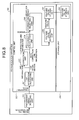
- FIG. 8 is a block diagram illustrating the configuration of the authentication apparatus according to the second embodiment.
- the line information calculating unit 301 is connected to a correction unit 401 and the difference calculating unit 304.
- the line information calculating unit 301 sends line information that is calculated for each region to the correction unit 401 and the difference calculating unit 304.
- the correction unit 401 receives, from the line information calculating unit 301, the line information calculated for each region and performs the correction on the line information calculated for each region.
- the correction unit 401 uses, as the correction method, for example, the local correction or the global correction.
- the correction unit 401 sends, to the difference calculating unit 304, the correction line information that is the corrected line information.
- the difference calculating unit 304 receives the correction line information from the correction unit 401 and receives, from the line information calculating unit 301, non-correction line information that is the line information to which no correction is subjected. Then, the difference calculating unit 304 calculates the difference between the correction line information and the non-correction line information and calculates the sum total difference.
- the correction selecting unit 305 compares the sum total difference calculated by the difference calculating unit 304 with the threshold. Then, if the difference is less than the threshold, the correction selecting unit 305 selects, as the line information contained in the fingerprint image, the non-correction line information and outputs it. In contrast, if the difference is greater than the threshold, the correction selecting unit 305 selects, as the line information contained in the fingerprint image, the correction line information and outputs it.
- the correction selecting unit 305 outputs, to the feature value extracting unit 306, non-correction line information that is the line information which is subjected to no correction. If the difference between the correction image and the non-correction image is large, the correction selecting unit 305 outputs, to the feature value extracting unit 306, the correction line information that is the line information subjected to the correction.
- a case in which the difference between the correction line information and the non-correction line information is small is a case in which, for example, the quality of the fingerprint image detected by the fingerprint image detecting unit 101 is high and the correction process is thus not required.
- the correction selecting unit 305 outputs, without performing correction, the non-correction line information which is subjected to no correction.
- the fingerprint image detecting unit 101 by performing the correction, a change is made to the fingerprint image that is detected by the fingerprint image detecting unit 101.
- a case in which the difference between the correction line information and the non-correction line information is small is a case in which the quality of the detected fingerprint image is high.
- the fingerprint image is output without processing it, i.e., without making a change by the correction.
- FIG. 9 is a flowchart illustrating the flow of the process performed by the authentication apparatus in the second embodiment.
- the difference calculating unit 304 converts the non-correction line information to a continuous vector field (Step S203).
- the correction unit 401 performs the correction on the line information calculated for each region of the fingerprint image (Step S204). Then, the difference calculating unit 304 converts, to the continuous vector field, the correction line information that is the line information corrected by the correction unit 401 (Step S205).
- the difference calculating unit 304 calculates the difference between the non-correction line information and the correction line information (Step S206).
- the correction selecting unit 305 compares the sum total difference with the threshold (Step S207). If the threshold is greater than the sum total difference (Yes at Step S207), the correction selecting unit 305 selects the non-correction line information (Step S208). In contrast, if the threshold is not greater than the sum total difference (No at Step S207), the correction selecting unit 305 selects the correction line information (Step S209).
- Steps S201 and S202 in FIG. 9 correspond to Steps S101 and S102 in FIG. 7 . Furthermore, Steps S210 and S211 in FIG. 9 correspond to Steps S111 and S112 in FIG. 7 .
- the difference between the non-correction line information and the correction line information is calculated, and the difference is compared with the threshold. Then, if the difference is less than the threshold, non-correction line information is selected. If the difference is greater than the threshold, the correction line information is selected. In other words, if the quality of the fingerprint image is high, no correction is selected as the correction method. If the quality of the fingerprint image is high, correction is selected as the correction method. Accordingly, it is possible to select the correction suitable for the quality of the image that is used for authentication.
- the correction image to which no correction is subjected is output without performing the correction.
- the process can be performed on biometric information, such as palm prints, finger veins, palm veins, and vascular patterns.
- biometric information such as palm prints, finger veins, palm veins, and vascular patterns.
- the present invention can be used for information other than the biometric information as long as characteristic line information that is used for authentication is contained.
- the present invention can be used for a process for authenticating banknotes.
- the method of inputting the feature value into the feature value storage unit 201 has been described; however, the present invention is not limited thereto.
- the authentication process can be performed using the extracted feature value. For example, it is possible to check the feature value obtained from the feature value extracting unit 306 with the feature value stored, in advance, in the feature value storage unit 201 and to output the result of the checking.
- a checking method in which a keyword (e.g., an ID) associated with the feature value is specified (one to one checking) or a checking method in which checking is performed without specifying an ID (one to many checking).
- the method performed on the fingerprint image detected by the fingerprint image detecting unit 101 has been described; however, the present invention is not limited thereto. It is also possible to perform a method on the fingerprint image stored in the storage unit in advance.
- the method of selecting, in accordance with the purpose, the local correction or the global correction has been described.
- the method of selecting, in accordance with the purpose, whether a correction is to be performed or not has been described.
- the present invention is not limited thereto. For example, when it is determined whether a correction is to be performed or not and if it is determined to be corrected, the local correction or the global correction can then be selected in accordance with the purpose.
- the correction methods i.e., the local correction, the global correction, and non-correction
- the correction methods i.e., the local correction, the global correction, and non-correction
- the whole or a part of the processes that are mentioned as being automatically performed can be manually performed.
- the process for selecting the correction method can be manually performed by a user.
- the flow of the processes, the control procedures, the specific names, and the information containing various kinds of data or parameters indicated in the above specification and drawings e.g., FIGS. 1 to 9 ) can be arbitrarily changed unless otherwise noted.
- each device illustrated in the drawings are only for conceptually illustrating the functions thereof and are not necessarily physically configured as illustrated in the drawings.
- the specific shape of a separate or integrated device is not limited to the drawings; however, all or part of the device can be configured by functionally or physically separating or integrating any of the units depending on various loads or use conditions.
- the feature value storage unit 201 and the fingerprint image detecting unit 101 can be physically separated or the local correction unit 302 and the global correction unit 303 can be integrated.
- FIG. 10 is a schematic diagram illustrating a program of the authentication apparatus according to the first embodiment.
- an authentication apparatus 3000 includes an operating unit 3001, a microphone 3002, a speaker 3003, a fingerprint image detector 304, a display 3005, a feature value storage unit 3006, a communication unit 3008, a CPU 3010, a ROM 3011, an HDD 3012, a RAM 3013, which are all connected via a bus 3009.
- the ROM 3011 stores therein, in advance, a control program having the same function as the line information calculating unit 301, the local correction unit 302, the global correction unit 303, the difference calculating unit 304, the correction selecting unit 305, the feature value extracting unit 306, and the feature value storing unit 307 described in the first embodiment.
- the ROM 3011 stores therein, in advance, a line information calculating program 3011a, a local correction program 3011b, a global correction program 3011c, a difference calculating program 3011d, a correction selection program 3011e, a feature value extracting program 3011f, and a feature value storing program 3011g.
- These programs 3011a to 3011g can appropriately be integrated or separated in the same manner as the components of the authentication apparatus illustrated in FIG. 2 .
- the CPU 3010 reads these programs 3011a to 3011g from the ROM 3011 and executes them so that these programs 3011a to 3011g can function as a line information calculating process 3010a, a local correction process 3010b, a global correction process 3010c, a difference calculating process 3010d, a correction selecting process 3010e, a feature value extracting process 3010f, and a feature value storing process 3010g.
- These processes 3010a to 3010g correspond to the line information calculating unit 301, the local correction unit 302, the global correction unit 303, the difference calculating unit 304, the correction selecting unit 305, and the feature value extracting unit 306, respectively, illustrated in FIG. 2 .
- the CPU 3010 executes the authentication program using fingerprint image data 3013a and line information data 3013b stored in the RAM 3013.
- the authentication apparatus described in the embodiments can be implemented by a program prepared in advance and executes by a computer such as a personal computer or a workstation.
- the program can be sent using a network such as the Internet.
- the program is stored in a computer-readable recording medium, such as a hard disk drive, a flexible disk (FD), a CD-ROM, an MO, a DVD.
- the computer then reads and executes the program from the above.
Landscapes
- Engineering & Computer Science (AREA)
- Quality & Reliability (AREA)
- Physics & Mathematics (AREA)
- General Physics & Mathematics (AREA)
- Multimedia (AREA)
- Theoretical Computer Science (AREA)
- Computer Vision & Pattern Recognition (AREA)
- Human Computer Interaction (AREA)
- Collating Specific Patterns (AREA)
- Image Analysis (AREA)
Abstract
Description
- The present invention relates to an authentication apparatus, an authentication method, and an authentication program.
- There is a known correction method of improving the precision of authentication by correcting image data including characteristic line information (e.g., fingerprints or palm prints, finger veins, palm veins, vascular patterns) that is used for the authentication. For example, local correction for correcting image data using local information and global correction for correcting image data using global information are known.
- Specifically, with the local correction, an apparatus performs correction, for each region of the image data, on characteristic line information contained in a region using characteristic line information that is contained in a neighboring region. The correction is performed by using, for example, a smoothing filter. With the global correction, an apparatus performs correction using line information contained in a larger region than a neighboring region. The correction is performed by using, for example, modeling using a formula.
-
- Patent Document 1: International Publication Pamphlet No.
WO 2005/086091 (Page 13 andFIG. 5 ) - Patent Document 2: Japanese Laid-open Patent Publication No.
2006-72553 Pages 1 to 5 andFIG. 1 ) - Patent Document 3: Japanese Laid-open Patent Publication No.
10-334237 Pages 1 to 8 andFIG. 1 ) - Patent Document 4: Japanese Laid-open Patent Publication No.
5-181956 Pages 1 to 4 andFIG. 1 ) - Patent Document 5: Japanese Laid-open Patent Publication No.
9-62836 Pages 1 to 3 andFIG. 1 ) - However, with the conventional methods described above, there is a problem in that, depending on the quality of the image that is used for the authentication, optimum correction cannot be obtained.
- For example, with the local correction described above, because noise that is larger than a smoothing filter cannot be corrected, the correction is not suitable for an image that contains a large amount of noise. Furthermore, with the global correction described above, for example, because detailed line information cannot be maintained in accordance with a correction process, the correction is not suitable for a high quality image, which does not contain a large amount of noise.
- Accordingly, the present invention has been conceived to solve the problems of the conventional technology described above, and an object thereof is to provide an authentication apparatus, an authentication method, and an authentication program that can select a correction method suitable for the image quality used for authentication.
- To solve the problem described above and achieve the object, Provided is a first correction unit that performs a correction, for each region obtained by dividing image data whose feature value extracted from the shape of a line is used for authentication, on line information indicating the shape of a line contained in a region by using the shape of a local line indicated by line information contained in a neighboring region of the region. Further, provided is a second correction unit that performs a correction, for the image data, on line information contained in the region by using the shape of a global line indicated by line information contained in a region larger than the neighboring region. Further provided is a calculating unit that calculates a difference between line information that is contained in the image data corrected by the first correction unit and line information that is contained in the image data corrected by the second correction unit. Further, provided is an output unit that compares the difference calculated by the calculating unit with a threshold and, if the difference is less than the threshold, outputs, as line information contained in the image data, line information corrected by the first correction unit and, if the difference is greater than the threshold, outputs, as line information contained in the image data, line information corrected by the second correction unit.
- It is possible to select a correction method suitable for the quality of the image that is used for authentication.
-
-
FIG. 1 is a schematic diagram illustrating the outline of an authentication apparatus according to a first embodiment. -
FIG. 2 is a block diagram illustrating the configuration of the authentication apparatus according to the first embodiment. -
FIG. 3 is a schematic diagram illustrating an example of a sobel filter in the first embodiment. -
FIG. 4 is a schematic diagram illustrating an example of a smoothing filter in the first embodiment. -
FIG. 5 is a schematic diagram illustrating local correction in the first embodiment. -
FIG. 6 is a schematic diagram illustrating a correction selecting unit in the first embodiment. -
FIG. 7 is a flowchart illustrating the flow of the process performed by the authentication apparatus in the first embodiment. -
FIG. 8 is a block diagram illustrating the configuration of an authentication apparatus according to a second embodiment. -
FIG. 9 is a flowchart illustrating the flow of the process performed by the authentication apparatus in the second embodiment. -
FIG. 10 is a schematic diagram illustrating a program of the authentication apparatus according to the first embodiment. -
- 100
- Authentication apparatus
- 101
- Fingerprint image detecting unit
- 200
- Storage unit
- 201
- Feature value storage unit
- 300
- Control unit
- 301
- Line information calculating unit
- 302
- Local correction unit
- 303
- Global correction unit
- 304
- Difference calculating unit
- 305
- Correction selecting unit
- 306
- Feature value extracting unit
- 307
- Feature value storing unit
- 401
- Correction unit
- Preferred embodiments of an authentication apparatus, an authentication method, and an authentication program according to the present invention will be described in detail with reference to the accompanying drawings. In the following, the outline of the authentication apparatus according to the embodiments, the configuration of the authentication apparatus, and the flow of the processing thereof will be described in the order they are listed in this sentence. Subsequently, another embodiment will be described.
- First, the outline of an authentication apparatus according to a first embodiment will be described with reference to
FIG. 1. FIG. 1 is a schematic diagram illustrating the outline of the authentication apparatus according to the first embodiment. - As illustrated in (1) of
FIG. 1 , the authentication apparatus according to the first embodiment receives a fingerprint image that is input from a user. Then, as illustrated in (2-1) ofFIG. 1 , the authentication apparatus performs local correction on the fingerprint image. For example, the authentication apparatus performs a correction using, for example, a smoothing filter. - Furthermore, as illustrated in (2-2) of
FIG. 1 , the authentication apparatus according to the first embodiment performs global correction on the fingerprint image. For example, the authentication apparatus performs correction by modeling using a formula in which it is assumed that the flow of line information is a phase diagram that is often used in physics. - Here, the authentication apparatus according to the first embodiment separately performs the local correction and the global correction. In other words, the authentication apparatus creates line information subjected to only the local correction and line information subjected to only the global correction.
- Then, as illustrated in (3) of
FIG. 1 , the authentication apparatus according to the first embodiment calculates the difference between the line information subjected to only the local correction and the line information subjected to only the global correction. - Thereafter, the authentication apparatus according to the first embodiment compares the difference with a threshold. If the difference is smaller than the threshold, as illustrated in (4-1) of
FIG. 1 , the authentication apparatus selects, as line information contained in image data, the line information that is corrected by the local correction and outputs the line information. If the difference is greater than the threshold, as illustrated in (4-2) ofFIG. 1 , the authentication apparatus selects, as the line information contained in the image data, the line information that is corrected by the global correction and outputs the line information. - In this way, the authentication apparatus according to the first embodiment can select a correction method suitable for the image quality that is used for the authentication. Specifically, the authentication apparatus separately uses, for fingerprint images, the local correction in which detailed information is maintained and the global correction in which correction effectiveness is large. If the difference between the two corrected fingerprints is small, the former method is used, whereas if the difference is large, the latter method is used. Accordingly, the authentication apparatus performs correction that is suitable for the quality of the fingerprint.
- In the following, the configuration of the
authentication apparatus 100 illustrated inFIG. 1 will be described with reference toFIG. 2. FIG. 2 is a block diagram illustrating the configuration of the authentication apparatus according to the first embodiment. As described inFIG. 2 , theauthentication apparatus 100 includes a fingerprintimage detecting unit 101, astorage unit 200, and acontrol unit 300. In the first embodiment, a method of extracting a feature value from an image of user's fingerprint and inputting the feature value to thestorage unit 200 as a feature value that is used at the time of authentication will be mainly described. - The fingerprint
image detecting unit 101 is connected to a lineinformation calculating unit 301, which will be described later. The fingerprintimage detecting unit 101 visualizes biometric information on a user by intermittently detecting multiple partial images and detects a fingerprint image (also referred to as "image data") whose feature value extracted from the shape of a line is used for authentication. - Examples of the fingerprint
image detecting unit 101 include a fingerprint sensor, which detects a fingerprint image of a user if a user's finger is pressed on it. Examples of the fingerprint sensor include a capacitance type fingerprint sensor, a thermal fingerprint sensor, an electric field fingerprint sensor, or an optical fingerprint sensor. - The fingerprint
image detecting unit 101 sends the detected fingerprint image to the lineinformation calculating unit 301. - The
storage unit 200 stores therein data necessary for processing authentication performed by thecontrol unit 300. Thestorage unit 200 includes a featurevalue storage unit 201 that is connected to a featurevalue storing unit 307, which will be described later. The featurevalue storage unit 201 stores therein a feature value that is used for authentication and is extracted from the shape of the line. The feature value mentioned here is information necessary for biometric authentication, and, if it is a fingerprint image, a branch point or an end point of a ridge corresponds to the feature value. The information stored in the featurevalue storage unit 201 is stored by the featurevalue storing unit 307, which will be described later. - The
control unit 300 performs various correction processes. For example, if thecontrol unit 300 receives a fingerprint image from the fingerprintimage detecting unit 101, thecontrol unit 300 extracts a feature value from a fingerprint image and inputs the feature value to the featurevalue storage unit 201. Furthermore, thecontrol unit 300 includes the lineinformation calculating unit 301, alocal correction unit 302, aglobal correction unit 303, adifference calculating unit 304, acorrection selecting unit 305, a featurevalue extracting unit 306, and the featurevalue storing unit 307. - The line
information calculating unit 301 is connected to the fingerprintimage detecting unit 101, thelocal correction unit 302, and theglobal correction unit 303. For the fingerprint image received from the fingerprintimage detecting unit 101, the lineinformation calculating unit 301 calculates line information (also referred to as a "ridge angle" or a "ridge direction") that indicates the shape of the line. Specifically, the lineinformation calculating unit 301 calculates, for each region of the fingerprint image, line information that is information about the shape of the line contained in that region. For example, the line information is calculated as "30 degrees" or "50 degrees". The line information mentioned here is an angle indicated by the shape of the line contained in the region. - For example, the line
information calculating unit 301 divides the fingerprint image into a region of "wxw" in size and partially differentiate, using a sobel filter like that illustrated inFIG. 3 , in the horizontal direction (x direction) and in the vertical direction (y direction) to obtain ∂x and ∂y. Then, the lineinformation calculating unit 301 calculates, from ∂x and ∂y using Equation (1), local line information θ (i, j) with respect to a center pixel (i, j) in each block. The sobel filter is a filter that is used when a vertical line edge or a horizontal line edge is detected.FIG. 3 is a schematic diagram illustrating an example of the sobel filter in the first embodiment. A filter in the vertical direction is illustrated in (1) ofFIG. 3 . A filter in the horizontal direction is illustrated in (2) ofFIG. 3 . -
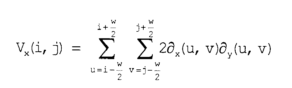


- In Equation (1), the direction in which the square error is minimum with respect to each pixel in the block is calculated using the gradient squared averaging method. In Equation (1), to make the equation easier to read, Vx and Vy are values of arctan parameters represented by the numerator and the denominator, respectively. Furthermore, the symbols "u" and "v" are variables that are repeatedly used in the formula.
- Furthermore, the line
information calculating unit 301 sends the line information calculated for each region to thelocal correction unit 302 and theglobal correction unit 303. - The
local correction unit 302 is connected to the lineinformation calculating unit 301 and thedifference calculating unit 304. Thelocal correction unit 302 receives, from the lineinformation calculating unit 301, the line information calculated for each region and then performs the local correction on the line information calculated for each region of the fingerprint image. Furthermore, thelocal correction unit 302 sends, to thedifference calculating unit 304, local correction line information that is the line information corrected using the local correction. - The local correction mentioned here is the correction performed, for each divided region of the fingerprint image, on the calculated line information on the divided region and the correction that is performed using the shape of the local line indicated by the line information contained in a neighboring region of the divided region. For example, the local correction corresponds to the correction using the smoothing filter illustrated in
FIG. 4. FIG. 4 is a schematic diagram illustrating an example of the smoothing filter in the first embodiment. - Furthermore, the local correction maintains detailed information on the line information; however, for example, as illustrated in (1) of
FIG. 5 , if the fingerprint image contains noise larger than the size of the smoothing filter, the local correction cannot correct that noise. In the example illustrated in (1) ofFIG. 5 , as no line information is contained in a region of the smoothing filter, as illustrated in (1) ofFIG. 5 , noise cannot be corrected by the local correction. - In other words, with the local correction, as illustrated in (2) of
FIG. 5 , correction can be performed only when noise that is smaller than the size of the smoothing filter is present.FIG. 5 is a schematic diagram illustrating the local correction in the first embodiment. The detailed information corresponds to, for example, small changes of the line information. - The
global correction unit 303 is connected to the lineinformation calculating unit 301 and thedifference calculating unit 304. Theglobal correction unit 303 receives, from the lineinformation calculating unit 301, the line information calculated for each region and performs the global correction on the line information calculated for each region of the fingerprint image. Furthermore, theglobal correction unit 303 sends, to thedifference calculating unit 304, global correction line information that is the line information corrected using the global correction. - The global correction mentioned here is the correction performed, for the fingerprint image and with respect to the calculated line information on the divided region, using the shape of the global line indicated by the line information calculated for each region contained in a larger region than a neighboring region. For example, the global correction corresponds to the correction performed by modeling using a formula in which it is assumed that the shape of the line or the flow of line information is a phase diagram that is often used in physics. Furthermore, the global correction has a significant effect on correction compared with the local correction but lacks detailed information on the line information.
- The
difference calculating unit 304 is connected to thelocal correction unit 302, theglobal correction unit 303, and thecorrection selecting unit 305. Thedifference calculating unit 304 receives the correction line information from thelocal correction unit 302 or receives the global correction line information from theglobal correction unit 303. Then, thedifference calculating unit 304 calculates the difference between the local correction line information and the global correction line information. For example, thedifference calculating unit 304, first, converts both the local correction line information and the global correction line information to continuous vector fields and, then calculates, for each region, the difference between the local correction line information and the global correction line information. Then, thedifference calculating unit 304 calculates a sum total difference that is the sum total value of the calculated differences. Furthermore, thedifference calculating unit 304 sends the calculated sum total difference to thecorrection selecting unit 305. - Here, the significance of the conversion to the continuous vector field will be described in brief. For differences for each region, if pieces of line information on arbitrary regions are, for example, "30 degrees" and "50 degrees", the
difference calculating unit 304 calculates the difference as "20 degrees". Here, when calculating the difference, thedifference calculating unit 304 considers only an angle difference. Accordingly, for example, thedifference calculating unit 304 treats "0 degrees" and "180 degrees" as the same degree of an angle and calculates the difference being "0 degrees". Converting to the continuous vector field is a process for treating, for example, "0 degrees" and "180 degrees" as the same value. - The
correction selecting unit 305 is connected to thedifference calculating unit 304 and the featurevalue extracting unit 306. Thecorrection selecting unit 305 receives, from thedifference calculating unit 304, the sum total difference and compares the sum total difference with a threshold. Then, as illustrated inFIG. 6 , if the difference is less than the threshold, thecorrection selecting unit 305 selects, as the line information contained in the fingerprint image, the local correction line information and outputs it to the featurevalue extracting unit 306. If the difference is greater than the threshold, thecorrection selecting unit 305 selects, as the line information contained in the fingerprint image, the global correction line information and outputs it to the featurevalue extracting unit 306.FIG. 6 is a schematic diagram illustrating the correction selecting unit in the first embodiment. - Specifically, if the difference between the local correction line information and the global correction line information is small, the
correction selecting unit 305 selects the local correction line information that is the line information subjected to the local correction in which detailed information on the line information is maintained. In contrast, if the difference between the local correction line information and the global correction line information is large, thecorrection selecting unit 305 selects the global correction line information that is the line information subjected to the global correction having the large correction effect. - A case in which the difference between the local correction line information and the global correction line information is large is a case in which, for example, the fingerprint image contains noise larger than the smoothing filter and such a large amount of noise can be corrected only by the global correction but cannot be corrected by the local correction. As illustrated in (2-1) of
FIG. 6 , if the fingerprintimage detecting unit 101 detects a fingerprint image containing a large amount of noise, as illustrated in (2-2) ofFIG. 6 , the local noise cannot be corrected by the correction line information, whereas the correction effect can be recognized in the global correction line information. As a result, because the difference between the local correction line information and the global correction line information is large, thecorrection selecting unit 305 selects the global correction line information as illustrated in (2-3) ofFIG. 6 . In other words, if a lot of cracks are present, thecorrection selecting unit 305 uses poor quality global correction. The poor quality mentioned here is the quality that cannot maintain detailed information when compared with the local correction. - Furthermore, a case in which the difference between the local correction line information and the global correction line information is small is a case in which, for example, the fingerprint image does not contain noise larger than the smoothing filter and thus noise in the fingerprint image can be corrected by either one of the local correction and the global correction. As illustrated in (1-1) of
FIG. 6 , if the fingerprintimage detecting unit 101 detects a fingerprint image that does not contain a large amount of noise, as illustrated in (1-2) ofFIG. 6 , the difference between the local correction line information and the global correction line information is small. Here, with the global correction line information, because small changes of the line information are not grasped due to a lack of detailed information, as illustrated in (1-3) ofFIG. 6 , thecorrection selecting unit 305 selects the local correction line information so as to hold the detailed information. In other words, if a small amount of cracks are present, thecorrection selecting unit 305 uses high quality local correction. - The threshold used by the
correction selecting unit 305 is set by, for example, a user. - The feature
value extracting unit 306 is connected to thecorrection selecting unit 305 and the featurevalue storing unit 307. The featurevalue extracting unit 306 receives, from thecorrection selecting unit 305, the local correction line information image of the global correction line information and extracts a feature value from the received line information. Then, the featurevalue extracting unit 306 sends the extracted feature value to the featurevalue storing unit 307. - The feature
value storing unit 307 is connected to the featurevalue extracting unit 306 and the featurevalue storage unit 201. The featurevalue storing unit 307 receives the feature value from the featurevalue extracting unit 306 and inputs the received feature value to the featurevalue storage unit 201. For example, when the featurevalue storing unit 307 inputs the feature value, the featurevalue storing unit 307 stores the feature value in the featurevalue storage unit 201 after encrypting the feature value. - In the following, the flow of the process performed by the
authentication apparatus 100 according to the first embodiment will be described with reference toFIG. 7. FIG. 7 is a flowchart illustrating the flow of the process performed by the authentication apparatus in the first embodiment. - If a fingerprint image has been input (Yes at Step S101), the line
information calculating unit 301 calculates, as a ridge angle of "30 degrees" or "50 degrees", line information for each region of the fingerprint image received from the fingerprint image detecting unit 101 (Step S102). - The
global correction unit 303 performs correction on each piece of line information using the global correction (Step S103). Then, thedifference calculating unit 304 converts, to a continuous vector field, the global correction line information that is the line information corrected by the global correction unit 303 (Step S104). - The
local correction unit 302 performs correction on each piece of line information using the local correction (Step S105). In other words, thelocal correction unit 302 performs the local correction on the line information calculated for each region of the fingerprint image. Then, thedifference calculating unit 304 converts, to a continuous vector field, the local correction line information that is the line information corrected by the local correction unit 302 (Step S106). - Then, the
difference calculating unit 304 calculates the difference between the local correction line information and the global correction line information (Step S107). Thecorrection selecting unit 305 compares the sum total difference with the threshold (Step S108). At this time, if the threshold is greater than the sum total difference (Yes at Step S108), thecorrection selecting unit 305 selects the local correction line information (Step S109). In contrast, if the threshold is not greater than the sum total difference (No at Step S108), thecorrection selecting unit 305 selects the global correction line information (Step S110). - Specifically, if the difference between the local correction line information and the global correction line information is small, the
correction selecting unit 305 selects the local correction line information that is the line information subjected to the local correction that maintains the detailed information on the line information. In contrast, if the difference between the local correction line information and the global correction line information is large, thecorrection selecting unit 305 selects the global correction line information that is the line information subjected to the global correction that has a large correction effect. - Then, the feature
value extracting unit 306 extracts the feature value from the line information that is received from the correction selecting unit 305 (Step S111). The featurevalue storing unit 307 stores the feature value in the feature value storage unit 201 (Step S112). - As described above, according to the first embodiment, the local correction and the global correction are separately performed on the fingerprint image, and the difference between the local correction line information and the global correction line information is calculated. Then, the difference is compared with the threshold. If the difference is less than the threshold, the local correction line information is output, whereas if the difference is greater than the threshold, the global correction line information is output. Accordingly, it is possible to select a correction method suitable for the quality of the image that is used for authentication.
- Furthermore, with the conventional technology, there is a trade off between a "noise removal effect" and "maintaining the detailed information". Specifically, with the conventional correction method, detailed information cannot be maintained depending on a fingerprint image and there may be a case in which line information is erroneously checked with a fingerprint of a different person that is similar to the fingerprint to be checked, and there may also be a case in which an effect such as cracks due to noise cannot be removed. However, according to the first embodiment, it is possible to select a correction method suitable for the quality of the image that is used for authentication. This makes it possible to perform a correction suitable for the quality of the fingerprint.
- In the above explanation, it has been mentioned that the local correction or the global correction is selected, in accordance with the purpose as the correction method of the first embodiment; however, the present invention is not limited thereto. It is also possible to select, in accordance with the purpose as the correction method, whether a correction is performed or not.
- Therefore, in the following, a method of selecting, in accordance with the purpose as the correction method of a second embodiment, whether a correction is performed or not will be described. In the following, components that are identical to those of the authentication apparatus in the first embodiment are either briefly described or descriptions thereof are omitted.
- The
authentication apparatus 100 according to the second embodiment will be described with reference toFIG. 8. FIG. 8 is a block diagram illustrating the configuration of the authentication apparatus according to the second embodiment. - As illustrated in
FIG. 8 , in the second embodiment, the lineinformation calculating unit 301 is connected to acorrection unit 401 and thedifference calculating unit 304. The lineinformation calculating unit 301 sends line information that is calculated for each region to thecorrection unit 401 and thedifference calculating unit 304. - In the second embodiment, the
correction unit 401 receives, from the lineinformation calculating unit 301, the line information calculated for each region and performs the correction on the line information calculated for each region. Here, thecorrection unit 401 uses, as the correction method, for example, the local correction or the global correction. Furthermore, thecorrection unit 401 sends, to thedifference calculating unit 304, the correction line information that is the corrected line information. - In the second embodiment, the
difference calculating unit 304 receives the correction line information from thecorrection unit 401 and receives, from the lineinformation calculating unit 301, non-correction line information that is the line information to which no correction is subjected. Then, thedifference calculating unit 304 calculates the difference between the correction line information and the non-correction line information and calculates the sum total difference. - In the second embodiment, the
correction selecting unit 305 compares the sum total difference calculated by thedifference calculating unit 304 with the threshold. Then, if the difference is less than the threshold, thecorrection selecting unit 305 selects, as the line information contained in the fingerprint image, the non-correction line information and outputs it. In contrast, if the difference is greater than the threshold, thecorrection selecting unit 305 selects, as the line information contained in the fingerprint image, the correction line information and outputs it. - Specifically, if the difference between the correction line information and the non-correction line information is small, the
correction selecting unit 305 outputs, to the featurevalue extracting unit 306, non-correction line information that is the line information which is subjected to no correction. If the difference between the correction image and the non-correction image is large, thecorrection selecting unit 305 outputs, to the featurevalue extracting unit 306, the correction line information that is the line information subjected to the correction. - Specifically, a case in which the difference between the correction line information and the non-correction line information is small is a case in which, for example, the quality of the fingerprint image detected by the fingerprint
image detecting unit 101 is high and the correction process is thus not required. In such a case, thecorrection selecting unit 305 outputs, without performing correction, the non-correction line information which is subjected to no correction. - In other words, by performing the correction, a change is made to the fingerprint image that is detected by the fingerprint
image detecting unit 101. A case in which the difference between the correction line information and the non-correction line information is small is a case in which the quality of the detected fingerprint image is high. Thus, the fingerprint image is output without processing it, i.e., without making a change by the correction. - In the following, the flow of the process performed by the
authentication apparatus 100 according to the second embodiment will be described with reference toFIG. 9. FIG. 9 is a flowchart illustrating the flow of the process performed by the authentication apparatus in the second embodiment. - In the second embodiment, if the fingerprint image has been input and the line information is calculated (Yes at Step S201 and Step S202), the
difference calculating unit 304 converts the non-correction line information to a continuous vector field (Step S203). - The
correction unit 401 performs the correction on the line information calculated for each region of the fingerprint image (Step S204). Then, thedifference calculating unit 304 converts, to the continuous vector field, the correction line information that is the line information corrected by the correction unit 401 (Step S205). - Then, the
difference calculating unit 304 calculates the difference between the non-correction line information and the correction line information (Step S206). Thecorrection selecting unit 305 compares the sum total difference with the threshold (Step S207). If the threshold is greater than the sum total difference (Yes at Step S207), thecorrection selecting unit 305 selects the non-correction line information (Step S208). In contrast, if the threshold is not greater than the sum total difference (No at Step S207), thecorrection selecting unit 305 selects the correction line information (Step S209). - Steps S201 and S202 in
FIG. 9 correspond to Steps S101 and S102 inFIG. 7 . Furthermore, Steps S210 and S211 inFIG. 9 correspond to Steps S111 and S112 inFIG. 7 . - As described above, according to the second embodiment, the difference between the non-correction line information and the correction line information is calculated, and the difference is compared with the threshold. Then, if the difference is less than the threshold, non-correction line information is selected. If the difference is greater than the threshold, the correction line information is selected. In other words, if the quality of the fingerprint image is high, no correction is selected as the correction method. If the quality of the fingerprint image is high, correction is selected as the correction method. Accordingly, it is possible to select the correction suitable for the quality of the image that is used for authentication.
- For example, if the quality of the fingerprint image detected by the fingerprint
image detecting unit 101 is high enough not to require the correction, the correction image to which no correction is subjected is output without performing the correction. - In the above explanation, embodiments of the present invention have been described; however, the present invention can be implemented as another embodiment other than the embodiments described above. Accordingly, in the following, another embodiment will be described.
- For example, in the first and second embodiments, the method of processing the fingerprint image has been described; however, the present invention is not limited thereto. For example, the process can be performed on biometric information, such as palm prints, finger veins, palm veins, and vascular patterns. Furthermore, the present invention can be used for information other than the biometric information as long as characteristic line information that is used for authentication is contained. For example, the present invention can be used for a process for authenticating banknotes.
- In the first embodiment, the method of inputting the feature value into the feature
value storage unit 201 has been described; however, the present invention is not limited thereto. The authentication process can be performed using the extracted feature value. For example, it is possible to check the feature value obtained from the featurevalue extracting unit 306 with the feature value stored, in advance, in the featurevalue storage unit 201 and to output the result of the checking. When performing the checking process of the feature values, for example, it is possible to use a checking method in which a keyword (e.g., an ID) associated with the feature value is specified (one to one checking) or a checking method in which checking is performed without specifying an ID (one to many checking). - Furthermore, in the first and second embodiments, the method performed on the fingerprint image detected by the fingerprint
image detecting unit 101 has been described; however, the present invention is not limited thereto. It is also possible to perform a method on the fingerprint image stored in the storage unit in advance. - In the first embodiment, the method of selecting, in accordance with the purpose, the local correction or the global correction has been described. In the second embodiment, the method of selecting, in accordance with the purpose, whether a correction is to be performed or not has been described. However, the present invention is not limited thereto. For example, when it is determined whether a correction is to be performed or not and if it is determined to be corrected, the local correction or the global correction can then be selected in accordance with the purpose. Furthermore, for example, it is also possible to select, in accordance with the purpose, the correction methods (i.e., the local correction, the global correction, and non-correction) by comparing the non-correction line information with the line information that is obtained by selecting, in accordance with the purpose, the local correction or the global correction.
- Of the processes described in the embodiments, the whole or a part of the processes that are mentioned as being automatically performed can be manually performed. For example, the process for selecting the correction method can be manually performed by a user. Furthermore, the flow of the processes, the control procedures, the specific names, and the information containing various kinds of data or parameters indicated in the above specification and drawings (e.g.,
FIGS. 1 to 9 ) can be arbitrarily changed unless otherwise noted. - The components of each device illustrated in the drawings are only for conceptually illustrating the functions thereof and are not necessarily physically configured as illustrated in the drawings. In other words, the specific shape of a separate or integrated device is not limited to the drawings; however, all or part of the device can be configured by functionally or physically separating or integrating any of the units depending on various loads or use conditions. For example, in the example illustrated in
FIG. 2 , the featurevalue storage unit 201 and the fingerprintimage detecting unit 101 can be physically separated or thelocal correction unit 302 and theglobal correction unit 303 can be integrated. - Various kinds of processing described in the embodiments can be implemented by executing programs written in advance for a computer such as a personal computer or a workstation. Accordingly, in the following, a computer that executes an authentication program having the same function as those described in the embodiments described above will be described as an example with reference to
FIG. 10. FIG. 10 is a schematic diagram illustrating a program of the authentication apparatus according to the first embodiment. - As illustrated in
FIG. 10 , anauthentication apparatus 3000 according to the first embodiment includes anoperating unit 3001, amicrophone 3002, aspeaker 3003, afingerprint image detector 304, adisplay 3005, a featurevalue storage unit 3006, acommunication unit 3008, aCPU 3010, aROM 3011, anHDD 3012, aRAM 3013, which are all connected via abus 3009. - The
ROM 3011 stores therein, in advance, a control program having the same function as the lineinformation calculating unit 301, thelocal correction unit 302, theglobal correction unit 303, thedifference calculating unit 304, thecorrection selecting unit 305, the featurevalue extracting unit 306, and the featurevalue storing unit 307 described in the first embodiment. In other words, as illustrated inFIG. 10 , theROM 3011 stores therein, in advance, a lineinformation calculating program 3011a, alocal correction program 3011b, aglobal correction program 3011c, adifference calculating program 3011d, acorrection selection program 3011e, a featurevalue extracting program 3011f, and a featurevalue storing program 3011g. Theseprograms 3011a to 3011g can appropriately be integrated or separated in the same manner as the components of the authentication apparatus illustrated inFIG. 2 . - As illustrated in
FIG. 10 , theCPU 3010 reads theseprograms 3011a to 3011g from theROM 3011 and executes them so that theseprograms 3011a to 3011g can function as a lineinformation calculating process 3010a, alocal correction process 3010b, aglobal correction process 3010c, adifference calculating process 3010d, acorrection selecting process 3010e, a featurevalue extracting process 3010f, and a featurevalue storing process 3010g. Theseprocesses 3010a to 3010g correspond to the lineinformation calculating unit 301, thelocal correction unit 302, theglobal correction unit 303, thedifference calculating unit 304, thecorrection selecting unit 305, and the featurevalue extracting unit 306, respectively, illustrated inFIG. 2 . - Then, the
CPU 3010 executes the authentication program usingfingerprint image data 3013a andline information data 3013b stored in theRAM 3013. - The authentication apparatus described in the embodiments can be implemented by a program prepared in advance and executes by a computer such as a personal computer or a workstation. The program can be sent using a network such as the Internet. Furthermore, the program is stored in a computer-readable recording medium, such as a hard disk drive, a flexible disk (FD), a CD-ROM, an MO, a DVD. The computer then reads and executes the program from the above.
Claims (2)
- An authentication apparatus comprising:a first correction unit that performs a correction, for each region obtained by dividing image data whose feature value extracted from the shape of a line is used for authentication, on line information indicating the shape of a line contained in a region by using the shape of a local line indicated by line information contained in a neighboring region of the region;a second correction unit that performs a correction, for the image data, on line information contained in the region by using the shape of a global line indicated by line information contained in a region larger than the neighboring region;a calculating unit that calculates a difference between line information that is contained in the image data corrected by the first correction unit and line information that is contained in the image data corrected by the second correction unit; andan output unit that compares the difference calculated by the calculating unit with a threshold and, if the difference is less than the threshold, outputs, as line information contained in the image data, line information corrected by the first correction unit and, if the difference is greater than the threshold, outputs, as line information contained in the image data, line information corrected by the second correction unit.
- An authentication apparatus comprising:a correction unit that performs a correction, for image data whose feature value extracted from the shape of a line is used for authentication, on line information contained in a region by using line information contained in the image data;a correction calculating unit that calculates a difference between line information contained in the image data corrected by the correction unit and line information contained in the image data that is not corrected by the correction unit; anda correction output unit that compares the difference calculated by the correction calculating unit with a threshold and, if the difference is less than the threshold, outputs line information contained in the image data that is not corrected by the correction unit and, if the difference is greater than the threshold, outputs, as line information contained in the image data, line information contained in the image data corrected by the correction unit.
Applications Claiming Priority (1)
| Application Number | Priority Date | Filing Date | Title |
|---|---|---|---|
| PCT/JP2008/061828 WO2010001447A1 (en) | 2008-06-30 | 2008-06-30 | Authentication device, authentication method and authentication program |
Publications (3)
| Publication Number | Publication Date |
|---|---|
| EP2296113A1 true EP2296113A1 (en) | 2011-03-16 |
| EP2296113A4 EP2296113A4 (en) | 2015-06-24 |
| EP2296113B1 EP2296113B1 (en) | 2019-11-13 |
Family
ID=41465563
Family Applications (1)
| Application Number | Title | Priority Date | Filing Date |
|---|---|---|---|
| EP08790741.6A Active EP2296113B1 (en) | 2008-06-30 | 2008-06-30 | Authentication device, authentication method and authentication program |
Country Status (5)
| Country | Link |
|---|---|
| US (1) | US8464323B2 (en) |
| EP (1) | EP2296113B1 (en) |
| JP (1) | JP5365632B2 (en) |
| CN (1) | CN102077247B (en) |
| WO (1) | WO2010001447A1 (en) |
Cited By (1)
| Publication number | Priority date | Publication date | Assignee | Title |
|---|---|---|---|---|
| EP2544147A4 (en) * | 2010-03-01 | 2016-08-10 | Fujitsu Ltd | DEVICE AND METHOD FOR MANAGING BIOLOGICAL INFORMATION |
Families Citing this family (4)
| Publication number | Priority date | Publication date | Assignee | Title |
|---|---|---|---|---|
| JP5971089B2 (en) * | 2012-11-14 | 2016-08-17 | 富士通株式会社 | Biological information correction apparatus, biological information correction method, and biological information correction computer program |
| JP7381997B2 (en) * | 2018-11-09 | 2023-11-16 | 日本電気株式会社 | Information processing system, information processing method and program |
| JP2020181040A (en) * | 2019-04-24 | 2020-11-05 | 三菱電機株式会社 | Display device |
| CN114124455B (en) * | 2021-10-22 | 2023-05-05 | 中国联合网络通信集团有限公司 | Short message verification method and short message verification system |
Family Cites Families (19)
| Publication number | Priority date | Publication date | Assignee | Title |
|---|---|---|---|---|
| JP2765335B2 (en) * | 1992-01-07 | 1998-06-11 | 日本電気株式会社 | Method and apparatus for smoothing ridge direction pattern |
| JP3647885B2 (en) * | 1993-05-07 | 2005-05-18 | 日本電信電話株式会社 | Image processing device |
| JP3813999B2 (en) | 1995-08-25 | 2006-08-23 | ジーイー横河メディカルシステム株式会社 | Image processing method and image processing apparatus |
| JP3695899B2 (en) | 1997-06-04 | 2005-09-14 | 三菱電機株式会社 | Fingerprint verification device |
| DE10038873C2 (en) * | 2000-08-09 | 2002-10-31 | Infineon Technologies Ag | Process for editing a fingerprint image and fingerprint sensor |
| KR100474760B1 (en) * | 2001-10-08 | 2005-03-08 | 엘지전자 주식회사 | Object domain detecting method for image |
| JP4027118B2 (en) * | 2002-02-25 | 2007-12-26 | 富士通株式会社 | User authentication method, program, and apparatus |
| CN1238809C (en) * | 2002-09-04 | 2006-01-25 | 长春鸿达光电子与生物统计识别技术有限公司 | Fingerprint identification method as well as fingerprint controlling method and system |
| JP3758042B2 (en) * | 2002-09-27 | 2006-03-22 | 日本電気株式会社 | Fingerprint authentication method / program / device |
| JP4286790B2 (en) * | 2003-03-14 | 2009-07-01 | 富士通株式会社 | Paper sheet identification method and paper sheet identification apparatus |
| JP2005004718A (en) * | 2003-05-16 | 2005-01-06 | Canon Inc | Signal processing apparatus and control method |
| JP2005051379A (en) * | 2003-07-31 | 2005-02-24 | Canon Inc | Image processing apparatus and image processing method |
| JP4029412B2 (en) * | 2004-03-04 | 2008-01-09 | 日本電気株式会社 | Fingerprint palmprint image processing system and fingerprint palmprint image processing method |
| JP4564804B2 (en) | 2004-08-31 | 2010-10-20 | セコム株式会社 | Biometric information verification device |
| JP2006072555A (en) | 2004-08-31 | 2006-03-16 | Secom Co Ltd | Biological information image correction device |
| JP4523476B2 (en) * | 2005-04-15 | 2010-08-11 | 三菱電機株式会社 | Noise removal device and program for noise removal device |
| CN100365646C (en) * | 2006-09-15 | 2008-01-30 | 哈尔滨工业大学 | High-precision Palmprint Recognition Method Based on Differential Operation |
| US8340370B2 (en) * | 2008-02-19 | 2012-12-25 | Nec Corporation | Pattern verification apparatus, pattern verification method, and program |
| JP5181956B2 (en) | 2008-03-03 | 2013-04-10 | 株式会社リコー | Electrophotographic equipment |
-
2008
- 2008-06-30 WO PCT/JP2008/061828 patent/WO2010001447A1/en not_active Ceased
- 2008-06-30 EP EP08790741.6A patent/EP2296113B1/en active Active
- 2008-06-30 CN CN2008801301278A patent/CN102077247B/en not_active Expired - Fee Related
- 2008-06-30 JP JP2010518834A patent/JP5365632B2/en not_active Expired - Fee Related
-
2010
- 2010-12-29 US US12/929,086 patent/US8464323B2/en not_active Expired - Fee Related
Non-Patent Citations (1)
| Title |
|---|
| See references of WO2010001447A1 * |
Cited By (1)
| Publication number | Priority date | Publication date | Assignee | Title |
|---|---|---|---|---|
| EP2544147A4 (en) * | 2010-03-01 | 2016-08-10 | Fujitsu Ltd | DEVICE AND METHOD FOR MANAGING BIOLOGICAL INFORMATION |
Also Published As
| Publication number | Publication date |
|---|---|
| CN102077247A (en) | 2011-05-25 |
| EP2296113B1 (en) | 2019-11-13 |
| US20110162068A1 (en) | 2011-06-30 |
| JPWO2010001447A1 (en) | 2011-12-15 |
| CN102077247B (en) | 2013-08-21 |
| EP2296113A4 (en) | 2015-06-24 |
| WO2010001447A1 (en) | 2010-01-07 |
| JP5365632B2 (en) | 2013-12-11 |
| US8464323B2 (en) | 2013-06-11 |
Similar Documents
| Publication | Publication Date | Title |
|---|---|---|
| CN111183437B (en) | Discrimination device and machine learning method | |
| KR101544279B1 (en) | Biometric information correction apparatus, biometric information correction method and a computer-readable recording medium for biometric information correction | |
| Agarwal et al. | Efficient hierarchical-PCA dimension reduction for hyperspectral imagery | |
| JP5012092B2 (en) | Biometric authentication device, biometric authentication program, and combined biometric authentication method | |
| EP1183638B1 (en) | Method and apparatus for creating a composite fingerprint image | |
| US9785819B1 (en) | Systems and methods for biometric image alignment | |
| EP2104059B1 (en) | Apparatus and method for processing image | |
| TWI390451B (en) | Registration device, registration method, authentication device and authentication method | |
| CN101499130B (en) | Fingerprint recognition method and fingerprint recognition system | |
| EP2518684B1 (en) | Fake finger determination device | |
| JP5560547B2 (en) | Biometric authentication device | |
| EP2105864B1 (en) | Authentication apparatus and authentication method | |
| CA2768504A1 (en) | Automatic identification of fingerprint inpainting target areas | |
| EP2296113A1 (en) | Authentication device, authentication method and authentication program | |
| WO2007088926A1 (en) | Image processing, image characteristic extracting and image checking devices, methods and programs, and image checking system | |
| EP2544147A1 (en) | Biological information management device and method | |
| EP2249309A1 (en) | Pattern matching device, pattern matching method, and program | |
| WO2017080279A1 (en) | Method, apparatus and terminal device for fingerprint identification | |
| WO2007146477A2 (en) | Method and apparatus for adaptive hierarchical processing of print images | |
| US20080040614A1 (en) | Authentication Systems and Authentication Method | |
| WO2018107574A1 (en) | Method and device for detecting see-through register anti-counterfeiting characteristics | |
| KR101676000B1 (en) | Method for Detecting and Security-Processing Fingerprint in Digital Documents made between Bank, Telecommunications Firm or Insurance Company and Private person | |
| US7668336B2 (en) | Extracting embedded information from a document | |
| CN110135431A (en) | The automatic identifying method and system of business license | |
| CN108009464B (en) | Fingerprint identification method and device |
Legal Events
| Date | Code | Title | Description |
|---|---|---|---|
| PUAI | Public reference made under article 153(3) epc to a published international application that has entered the european phase |
Free format text: ORIGINAL CODE: 0009012 |
|
| 17P | Request for examination filed |
Effective date: 20110124 |
|
| AK | Designated contracting states |
Kind code of ref document: A1 Designated state(s): AT BE BG CH CY CZ DE DK EE ES FI FR GB GR HR HU IE IS IT LI LT LU LV MC MT NL NO PL PT RO SE SI SK TR |
|
| AX | Request for extension of the european patent |
Extension state: AL BA MK RS |
|
| DAX | Request for extension of the european patent (deleted) | ||
| RA4 | Supplementary search report drawn up and despatched (corrected) |
Effective date: 20150521 |
|
| RIC1 | Information provided on ipc code assigned before grant |
Ipc: G06T 7/00 20060101AFI20150515BHEP Ipc: G06K 9/00 20060101ALI20150515BHEP Ipc: G06K 9/36 20060101ALI20150515BHEP Ipc: G06K 9/03 20060101ALI20150515BHEP |
|
| STAA | Information on the status of an ep patent application or granted ep patent |
Free format text: STATUS: EXAMINATION IS IN PROGRESS |
|
| 17Q | First examination report despatched |
Effective date: 20180103 |
|
| GRAP | Despatch of communication of intention to grant a patent |
Free format text: ORIGINAL CODE: EPIDOSNIGR1 |
|
| STAA | Information on the status of an ep patent application or granted ep patent |
Free format text: STATUS: GRANT OF PATENT IS INTENDED |
|
| INTG | Intention to grant announced |
Effective date: 20190607 |
|
| GRAS | Grant fee paid |
Free format text: ORIGINAL CODE: EPIDOSNIGR3 |
|
| GRAA | (expected) grant |
Free format text: ORIGINAL CODE: 0009210 |
|
| STAA | Information on the status of an ep patent application or granted ep patent |
Free format text: STATUS: THE PATENT HAS BEEN GRANTED |
|
| AK | Designated contracting states |
Kind code of ref document: B1 Designated state(s): AT BE BG CH CY CZ DE DK EE ES FI FR GB GR HR HU IE IS IT LI LT LU LV MC MT NL NO PL PT RO SE SI SK TR |
|
| REG | Reference to a national code |
Ref country code: GB Ref legal event code: FG4D |
|
| REG | Reference to a national code |
Ref country code: CH Ref legal event code: EP Ref country code: AT Ref legal event code: REF Ref document number: 1202451 Country of ref document: AT Kind code of ref document: T Effective date: 20191115 |
|
| REG | Reference to a national code |
Ref country code: DE Ref legal event code: R096 Ref document number: 602008061637 Country of ref document: DE |
|
| REG | Reference to a national code |
Ref country code: IE Ref legal event code: FG4D |
|
| REG | Reference to a national code |
Ref country code: NL Ref legal event code: MP Effective date: 20191113 |
|
| REG | Reference to a national code |
Ref country code: LT Ref legal event code: MG4D |
|
| PG25 | Lapsed in a contracting state [announced via postgrant information from national office to epo] |
Ref country code: GR Free format text: LAPSE BECAUSE OF FAILURE TO SUBMIT A TRANSLATION OF THE DESCRIPTION OR TO PAY THE FEE WITHIN THE PRESCRIBED TIME-LIMIT Effective date: 20200214 Ref country code: NO Free format text: LAPSE BECAUSE OF FAILURE TO SUBMIT A TRANSLATION OF THE DESCRIPTION OR TO PAY THE FEE WITHIN THE PRESCRIBED TIME-LIMIT Effective date: 20200213 Ref country code: LT Free format text: LAPSE BECAUSE OF FAILURE TO SUBMIT A TRANSLATION OF THE DESCRIPTION OR TO PAY THE FEE WITHIN THE PRESCRIBED TIME-LIMIT Effective date: 20191113 Ref country code: FI Free format text: LAPSE BECAUSE OF FAILURE TO SUBMIT A TRANSLATION OF THE DESCRIPTION OR TO PAY THE FEE WITHIN THE PRESCRIBED TIME-LIMIT Effective date: 20191113 Ref country code: BG Free format text: LAPSE BECAUSE OF FAILURE TO SUBMIT A TRANSLATION OF THE DESCRIPTION OR TO PAY THE FEE WITHIN THE PRESCRIBED TIME-LIMIT Effective date: 20200213 Ref country code: NL Free format text: LAPSE BECAUSE OF FAILURE TO SUBMIT A TRANSLATION OF THE DESCRIPTION OR TO PAY THE FEE WITHIN THE PRESCRIBED TIME-LIMIT Effective date: 20191113 Ref country code: PT Free format text: LAPSE BECAUSE OF FAILURE TO SUBMIT A TRANSLATION OF THE DESCRIPTION OR TO PAY THE FEE WITHIN THE PRESCRIBED TIME-LIMIT Effective date: 20200313 Ref country code: ES Free format text: LAPSE BECAUSE OF FAILURE TO SUBMIT A TRANSLATION OF THE DESCRIPTION OR TO PAY THE FEE WITHIN THE PRESCRIBED TIME-LIMIT Effective date: 20191113 Ref country code: SE Free format text: LAPSE BECAUSE OF FAILURE TO SUBMIT A TRANSLATION OF THE DESCRIPTION OR TO PAY THE FEE WITHIN THE PRESCRIBED TIME-LIMIT Effective date: 20191113 Ref country code: LV Free format text: LAPSE BECAUSE OF FAILURE TO SUBMIT A TRANSLATION OF THE DESCRIPTION OR TO PAY THE FEE WITHIN THE PRESCRIBED TIME-LIMIT Effective date: 20191113 Ref country code: PL Free format text: LAPSE BECAUSE OF FAILURE TO SUBMIT A TRANSLATION OF THE DESCRIPTION OR TO PAY THE FEE WITHIN THE PRESCRIBED TIME-LIMIT Effective date: 20191113 |
|
| PG25 | Lapsed in a contracting state [announced via postgrant information from national office to epo] |
Ref country code: IS Free format text: LAPSE BECAUSE OF FAILURE TO SUBMIT A TRANSLATION OF THE DESCRIPTION OR TO PAY THE FEE WITHIN THE PRESCRIBED TIME-LIMIT Effective date: 20200313 Ref country code: HR Free format text: LAPSE BECAUSE OF FAILURE TO SUBMIT A TRANSLATION OF THE DESCRIPTION OR TO PAY THE FEE WITHIN THE PRESCRIBED TIME-LIMIT Effective date: 20191113 |
|
| PG25 | Lapsed in a contracting state [announced via postgrant information from national office to epo] |
Ref country code: CZ Free format text: LAPSE BECAUSE OF FAILURE TO SUBMIT A TRANSLATION OF THE DESCRIPTION OR TO PAY THE FEE WITHIN THE PRESCRIBED TIME-LIMIT Effective date: 20191113 Ref country code: RO Free format text: LAPSE BECAUSE OF FAILURE TO SUBMIT A TRANSLATION OF THE DESCRIPTION OR TO PAY THE FEE WITHIN THE PRESCRIBED TIME-LIMIT Effective date: 20191113 Ref country code: DK Free format text: LAPSE BECAUSE OF FAILURE TO SUBMIT A TRANSLATION OF THE DESCRIPTION OR TO PAY THE FEE WITHIN THE PRESCRIBED TIME-LIMIT Effective date: 20191113 Ref country code: EE Free format text: LAPSE BECAUSE OF FAILURE TO SUBMIT A TRANSLATION OF THE DESCRIPTION OR TO PAY THE FEE WITHIN THE PRESCRIBED TIME-LIMIT Effective date: 20191113 |
|
| REG | Reference to a national code |
Ref country code: DE Ref legal event code: R097 Ref document number: 602008061637 Country of ref document: DE |
|
| REG | Reference to a national code |
Ref country code: AT Ref legal event code: MK05 Ref document number: 1202451 Country of ref document: AT Kind code of ref document: T Effective date: 20191113 |
|
| PG25 | Lapsed in a contracting state [announced via postgrant information from national office to epo] |
Ref country code: SK Free format text: LAPSE BECAUSE OF FAILURE TO SUBMIT A TRANSLATION OF THE DESCRIPTION OR TO PAY THE FEE WITHIN THE PRESCRIBED TIME-LIMIT Effective date: 20191113 |
|
| PLBE | No opposition filed within time limit |
Free format text: ORIGINAL CODE: 0009261 |
|
| STAA | Information on the status of an ep patent application or granted ep patent |
Free format text: STATUS: NO OPPOSITION FILED WITHIN TIME LIMIT |
|
| 26N | No opposition filed |
Effective date: 20200814 |
|
| PG25 | Lapsed in a contracting state [announced via postgrant information from national office to epo] |
Ref country code: AT Free format text: LAPSE BECAUSE OF FAILURE TO SUBMIT A TRANSLATION OF THE DESCRIPTION OR TO PAY THE FEE WITHIN THE PRESCRIBED TIME-LIMIT Effective date: 20191113 Ref country code: SI Free format text: LAPSE BECAUSE OF FAILURE TO SUBMIT A TRANSLATION OF THE DESCRIPTION OR TO PAY THE FEE WITHIN THE PRESCRIBED TIME-LIMIT Effective date: 20191113 |
|
| REG | Reference to a national code |
Ref country code: DE Ref legal event code: R082 Ref document number: 602008061637 Country of ref document: DE Representative=s name: HL KEMPNER PATENTANWAELTE, SOLICITORS (ENGLAND, DE Ref country code: DE Ref legal event code: R082 Ref document number: 602008061637 Country of ref document: DE Representative=s name: HL KEMPNER PATENTANWALT, RECHTSANWALT, SOLICIT, DE |
|
| PG25 | Lapsed in a contracting state [announced via postgrant information from national office to epo] |
Ref country code: IT Free format text: LAPSE BECAUSE OF FAILURE TO SUBMIT A TRANSLATION OF THE DESCRIPTION OR TO PAY THE FEE WITHIN THE PRESCRIBED TIME-LIMIT Effective date: 20191113 Ref country code: MC Free format text: LAPSE BECAUSE OF FAILURE TO SUBMIT A TRANSLATION OF THE DESCRIPTION OR TO PAY THE FEE WITHIN THE PRESCRIBED TIME-LIMIT Effective date: 20191113 |
|
| REG | Reference to a national code |
Ref country code: CH Ref legal event code: PL |
|
| PG25 | Lapsed in a contracting state [announced via postgrant information from national office to epo] |
Ref country code: LU Free format text: LAPSE BECAUSE OF NON-PAYMENT OF DUE FEES Effective date: 20200630 |
|
| REG | Reference to a national code |
Ref country code: BE Ref legal event code: MM Effective date: 20200630 |
|
| PG25 | Lapsed in a contracting state [announced via postgrant information from national office to epo] |
Ref country code: CH Free format text: LAPSE BECAUSE OF NON-PAYMENT OF DUE FEES Effective date: 20200630 Ref country code: IE Free format text: LAPSE BECAUSE OF NON-PAYMENT OF DUE FEES Effective date: 20200630 Ref country code: LI Free format text: LAPSE BECAUSE OF NON-PAYMENT OF DUE FEES Effective date: 20200630 |
|
| PG25 | Lapsed in a contracting state [announced via postgrant information from national office to epo] |
Ref country code: BE Free format text: LAPSE BECAUSE OF NON-PAYMENT OF DUE FEES Effective date: 20200630 |
|
| PG25 | Lapsed in a contracting state [announced via postgrant information from national office to epo] |
Ref country code: TR Free format text: LAPSE BECAUSE OF FAILURE TO SUBMIT A TRANSLATION OF THE DESCRIPTION OR TO PAY THE FEE WITHIN THE PRESCRIBED TIME-LIMIT Effective date: 20191113 Ref country code: MT Free format text: LAPSE BECAUSE OF FAILURE TO SUBMIT A TRANSLATION OF THE DESCRIPTION OR TO PAY THE FEE WITHIN THE PRESCRIBED TIME-LIMIT Effective date: 20191113 Ref country code: CY Free format text: LAPSE BECAUSE OF FAILURE TO SUBMIT A TRANSLATION OF THE DESCRIPTION OR TO PAY THE FEE WITHIN THE PRESCRIBED TIME-LIMIT Effective date: 20191113 |
|
| PGFP | Annual fee paid to national office [announced via postgrant information from national office to epo] |
Ref country code: FR Payment date: 20230510 Year of fee payment: 16 Ref country code: DE Payment date: 20230502 Year of fee payment: 16 |
|
| PGFP | Annual fee paid to national office [announced via postgrant information from national office to epo] |
Ref country code: GB Payment date: 20230511 Year of fee payment: 16 |
|
| REG | Reference to a national code |
Ref country code: DE Ref legal event code: R119 Ref document number: 602008061637 Country of ref document: DE |
|
| GBPC | Gb: european patent ceased through non-payment of renewal fee |
Effective date: 20240630 |
|
| PG25 | Lapsed in a contracting state [announced via postgrant information from national office to epo] |
Ref country code: DE Free format text: LAPSE BECAUSE OF NON-PAYMENT OF DUE FEES Effective date: 20250101 |
|
| PG25 | Lapsed in a contracting state [announced via postgrant information from national office to epo] |
Ref country code: FR Free format text: LAPSE BECAUSE OF NON-PAYMENT OF DUE FEES Effective date: 20240630 |
|
| PG25 | Lapsed in a contracting state [announced via postgrant information from national office to epo] |
Ref country code: GB Free format text: LAPSE BECAUSE OF NON-PAYMENT OF DUE FEES Effective date: 20240630 |