EP2296052A2 - Transfer device and image forming apparatus including same - Google Patents
Transfer device and image forming apparatus including same Download PDFInfo
- Publication number
- EP2296052A2 EP2296052A2 EP10175009A EP10175009A EP2296052A2 EP 2296052 A2 EP2296052 A2 EP 2296052A2 EP 10175009 A EP10175009 A EP 10175009A EP 10175009 A EP10175009 A EP 10175009A EP 2296052 A2 EP2296052 A2 EP 2296052A2
- Authority
- EP
- European Patent Office
- Prior art keywords
- intermediate transfer
- transfer belt
- bearing members
- image bearing
- image
- Prior art date
- Legal status (The legal status is an assumption and is not a legal conclusion. Google has not performed a legal analysis and makes no representation as to the accuracy of the status listed.)
- Withdrawn
Links
- 239000000314 lubricant Substances 0.000 claims abstract description 40
- 239000002131 composite material Substances 0.000 claims abstract description 17
- 238000011144 upstream manufacturing Methods 0.000 claims abstract description 12
- 238000004140 cleaning Methods 0.000 claims description 27
- 230000001186 cumulative effect Effects 0.000 claims description 3
- 239000003795 chemical substances by application Substances 0.000 claims 2
- 230000007257 malfunction Effects 0.000 claims 1
- 108091008695 photoreceptors Proteins 0.000 description 48
- 238000010586 diagram Methods 0.000 description 16
- 238000000034 method Methods 0.000 description 8
- 230000007246 mechanism Effects 0.000 description 7
- 230000002159 abnormal effect Effects 0.000 description 6
- 239000000463 material Substances 0.000 description 4
- 239000002184 metal Substances 0.000 description 4
- 230000008569 process Effects 0.000 description 4
- 230000008901 benefit Effects 0.000 description 3
- 239000003086 colorant Substances 0.000 description 3
- 239000000470 constituent Substances 0.000 description 3
- 230000001629 suppression Effects 0.000 description 3
- 238000007796 conventional method Methods 0.000 description 2
- 229920005989 resin Polymers 0.000 description 2
- 239000011347 resin Substances 0.000 description 2
- 229920006311 Urethane elastomer Polymers 0.000 description 1
- 230000005540 biological transmission Effects 0.000 description 1
- 230000000052 comparative effect Effects 0.000 description 1
- 235000014113 dietary fatty acids Nutrition 0.000 description 1
- 239000000428 dust Substances 0.000 description 1
- 229920001971 elastomer Polymers 0.000 description 1
- 230000005684 electric field Effects 0.000 description 1
- 239000004744 fabric Substances 0.000 description 1
- 229930195729 fatty acid Natural products 0.000 description 1
- 239000000194 fatty acid Substances 0.000 description 1
- 150000004665 fatty acids Chemical class 0.000 description 1
- 125000001183 hydrocarbyl group Chemical group 0.000 description 1
- 238000004519 manufacturing process Methods 0.000 description 1
- 238000012986 modification Methods 0.000 description 1
- 230000004048 modification Effects 0.000 description 1
- 230000002093 peripheral effect Effects 0.000 description 1
- 229920000728 polyester Polymers 0.000 description 1
- 239000000843 powder Substances 0.000 description 1
- 238000002360 preparation method Methods 0.000 description 1
- 238000003825 pressing Methods 0.000 description 1
- 230000002265 prevention Effects 0.000 description 1
- 230000000717 retained effect Effects 0.000 description 1
- 150000003839 salts Chemical class 0.000 description 1
- 239000012798 spherical particle Substances 0.000 description 1
- 230000000087 stabilizing effect Effects 0.000 description 1
- 239000000126 substance Substances 0.000 description 1
Images


Classifications
-
- G—PHYSICS
- G03—PHOTOGRAPHY; CINEMATOGRAPHY; ANALOGOUS TECHNIQUES USING WAVES OTHER THAN OPTICAL WAVES; ELECTROGRAPHY; HOLOGRAPHY
- G03G—ELECTROGRAPHY; ELECTROPHOTOGRAPHY; MAGNETOGRAPHY
- G03G15/00—Apparatus for electrographic processes using a charge pattern
- G03G15/14—Apparatus for electrographic processes using a charge pattern for transferring a pattern to a second base
- G03G15/16—Apparatus for electrographic processes using a charge pattern for transferring a pattern to a second base of a toner pattern, e.g. a powder pattern, e.g. magnetic transfer
- G03G15/1605—Apparatus for electrographic processes using a charge pattern for transferring a pattern to a second base of a toner pattern, e.g. a powder pattern, e.g. magnetic transfer using at least one intermediate support
- G03G15/161—Apparatus for electrographic processes using a charge pattern for transferring a pattern to a second base of a toner pattern, e.g. a powder pattern, e.g. magnetic transfer using at least one intermediate support with means for handling the intermediate support, e.g. heating, cleaning, coating with a transfer agent
-
- G—PHYSICS
- G03—PHOTOGRAPHY; CINEMATOGRAPHY; ANALOGOUS TECHNIQUES USING WAVES OTHER THAN OPTICAL WAVES; ELECTROGRAPHY; HOLOGRAPHY
- G03G—ELECTROGRAPHY; ELECTROPHOTOGRAPHY; MAGNETOGRAPHY
- G03G15/00—Apparatus for electrographic processes using a charge pattern
- G03G15/01—Apparatus for electrographic processes using a charge pattern for producing multicoloured copies
- G03G15/0105—Details of unit
- G03G15/0131—Details of unit for transferring a pattern to a second base
- G03G15/0136—Details of unit for transferring a pattern to a second base transfer member separable from recording member or vice versa, mode switching
-
- G—PHYSICS
- G03—PHOTOGRAPHY; CINEMATOGRAPHY; ANALOGOUS TECHNIQUES USING WAVES OTHER THAN OPTICAL WAVES; ELECTROGRAPHY; HOLOGRAPHY
- G03G—ELECTROGRAPHY; ELECTROPHOTOGRAPHY; MAGNETOGRAPHY
- G03G15/00—Apparatus for electrographic processes using a charge pattern
- G03G15/01—Apparatus for electrographic processes using a charge pattern for producing multicoloured copies
- G03G15/0142—Structure of complete machines
- G03G15/0178—Structure of complete machines using more than one reusable electrographic recording member, e.g. one for every monocolour image
- G03G15/0194—Structure of complete machines using more than one reusable electrographic recording member, e.g. one for every monocolour image primary transfer to the final recording medium
-
- G—PHYSICS
- G03—PHOTOGRAPHY; CINEMATOGRAPHY; ANALOGOUS TECHNIQUES USING WAVES OTHER THAN OPTICAL WAVES; ELECTROGRAPHY; HOLOGRAPHY
- G03G—ELECTROGRAPHY; ELECTROPHOTOGRAPHY; MAGNETOGRAPHY
- G03G2215/00—Apparatus for electrophotographic processes
- G03G2215/01—Apparatus for electrophotographic processes for producing multicoloured copies
- G03G2215/0103—Plural electrographic recording members
- G03G2215/0119—Linear arrangement adjacent plural transfer points
- G03G2215/0122—Linear arrangement adjacent plural transfer points primary transfer to an intermediate transfer belt
- G03G2215/0125—Linear arrangement adjacent plural transfer points primary transfer to an intermediate transfer belt the linear arrangement being horizontal or slanted
- G03G2215/0132—Linear arrangement adjacent plural transfer points primary transfer to an intermediate transfer belt the linear arrangement being horizontal or slanted vertical medium transport path at the secondary transfer
Definitions
- Exemplary aspects of the present invention generally relate to a transfer device and an image forming apparatus, such as a copier, a facsimile machine, a printer, or a multi-functional system including a combination thereof, and more particularly, to a transfer device including a belt-type transfer member and an image forming apparatus including the transfer device.
- a transfer device employed in, but not limited to, image forming apparatuses, such as copiers, printers, facsimile machines, and multifunctional systems including at least two of these functions, in which an endless looped belt is employed as an intermediate transfer member for transferring images.
- a color image forming apparatus is equipped with a plurality of cylindrical photoreceptors serving as image bearing members, one for each color, and a belt-type intermediate transfer member (hereinafter referred to as an intermediate transfer belt).
- the intermediate transfer belt is disposed across from and in contact with the photoreceptors which rotate at a certain speed, and rotates at the same peripheral speed as that of the photoreceptors.
- Such a color image forming apparatus equipped with the intermediate transfer belt includes also a developing device, a primary transfer device, and a secondary transfer device.
- the developing device develops latent images of different colors formed on the photoreceptors into toner images.
- the primary transfer device transfers overlappingly and sequentially the toner images formed on the photoreceptors onto the intermediate transfer belt, thereby forming a composite color toner image thereon.
- the secondary transfer device transfers the composite color toner image from the intermediate transfer belt onto a transfer material, for example, a recording medium, thereby ultimately forming a color image.
- the toner of the composite toner image is transferred completely onto the transfer material. That is, undesirably, some residual toner remains on the intermediate transfer belt.
- a cleaning device often constructed of a cleaning blade made of rubber or resin, is provided to clean the residual toner from the intermediate transfer belt.
- removal of the residual toner by the cleaning blade is becoming more difficult in recent years as toner consisting of very fine spherical particles increasingly comes to be used to satisfy growing market demand for the production of images of ever-higher quality.
- a conventional method of facilitating removal of residual toner employs a lubricant which is applied on the surface of the intermediate transfer belt to reduce adherence between the intermediate transfer belt and the residual toner.
- the lubricant is applied on the intermediate transfer belt using an application member, for example, a brush roller.
- the brush roller consists of a metal core around which a fabric with brush bristles is attached, thereby rubbing the lubricant retained on the brush bristles onto the intermediate transfer belt.
- the lubricant is best accomplished in the absence of residual toner.
- the lubricant is usually applied to the intermediate transfer belt after the intermediate transfer belt is cleaned by the cleaning device.
- a roller (hereinafter referred to as an opposing roller) is disposed opposite the brush roller through the intermediate transfer belt (that is, on a side of the belt opposite the side on which the brush roller is disposed) to press the spanned surface of the intermediate transfer belt against the tip of the brush roller so that the tip of the brush roller can reliably contact the surface of the intermediate transfer belt while preventing rippling of the intermediate transfer belt as well.
- the amount of the tip of the brush bristles of the brush roller engaging the belt surface is approximately 1 mm.
- the tension of the intermediate transfer belt causes the contact pressure between the photoreceptors and the primary transfer rollers to vary. This also results in improper transfer of the toner images.
- a transfer device in one illustrative embodiment of the present invention, includes a pair of rollers, a rotatable intermediate transfer belt, a plurality of transfer members, a lubricant applicator, an opposing member, and a pressure member.
- the rotatable intermediate transfer belt is wound around and stretched between the pair of rollers to face a plurality of image bearing members for bearing toner images.
- Each of the plurality of transfer members faces a respective one of the plurality of the image bearing members through the intermediate transfer belt to transfer overlappingly the toner images onto the intermediate transfer belt to form a composite toner image thereon.
- the lubricant applicator is disposed upstream from the plurality of the image bearing members in a direction of rotation of the intermediate transfer belt and on the same plane on which the plurality of the image bearing members is disposed, to apply a lubricant to the intermediate transfer belt.
- the opposing member is disposed opposite the lubricant applicator through the intermediate transfer belt and contacts the intermediate transfer belt against the lubricant applicator.
- the pressure member is disposed upstream from the plurality of the image bearing members and downstream from the lubricant applicator in the direction of rotation of the intermediate transfer belt, to press against the intermediate transfer belt.
- an image forming apparatus in another illustrative embodiment of the present invention, includes a plurality of image bearing members, a developing device, and a transfer device.
- the plurality of image bearing members bears an electrostatic latent image on a surface thereof.
- the developing device develops the electrostatic latent images formed on the image bearing members using toner to form a toner image.
- the transfer device includes a pair of rollers, a rotatable intermediate transfer belt, a plurality of transfer members, a lubricant applicator, an opposing members, and a pressure member.
- the rotatable intermediate transfer belt is wound around and stretched between the pair of rollers to face a plurality of image bearing members for bearing toner images.
- Each of the plurality of transfer members faces a respective one of the plurality of the image bearing members through the intermediate transfer belt to transfer overlappingly the toner images onto the intermediate transfer belt to form a composite toner image thereon.
- the lubricant applicator is disposed upstream from the plurality of the image bearing members in a direction of rotation of the intermediate transfer belt and on the same plane on which the plurality of the image bearing members is disposed, to apply a lubricant to the intermediate transfer belt.
- the opposing member is disposed opposite the lubricant applicator through the intermediate transfer belt and contacts the intermediate transfer belt against the lubricant applicator.
- the pressure member is disposed upstream from the plurality of the image bearing members and downstream from the lubricant applicator in the direction of rotation of the intermediate transfer belt, to press against the intermediate transfer belt.
- thermos as first, second, etc. may be used herein to describe various elements, components, regions, layers and/or sections, it should be understood that such elements, components, regions, layers and/or sections are not limited thereby because such terms are relative, that is, used only to distinguish one element, component, region, layer or section from another region, layer or section.
- a first element, component, region, layer or section discussed below could be termed a second element, component, region, layer or section without departing from the teachings of the present invention.
- paper is the medium from which is made a sheet on which an image is to be formed. It should be noted, however, that other printable media are available in sheet form, and accordingly their use here is included. Thus, solely for simplicity, although this Detailed Description section refers to paper, sheets thereof, paper feeder, etc., it should be understood that the sheets, etc., are not limited only to paper, but includes other printable media as well.
- FIG. 1 one example of an image forming apparatus according to an illustrative embodiment of the present invention is described.
- FIG. 1 is a schematic diagram illustrating a full-color printer as an example of an image forming apparatus 100 according to the illustrative embodiment can be employed.
- the image forming apparatus 100 includes, but is not limited to a printer, a copier, and a multifunctional system including at least two of these functions.
- a main body 101 of the image forming apparatus 100 includes a transfer device 20, charging devices 2Y, 2M, 2C, and 2K, developing devices 4Y, 4M, 4C, and 4K, an intermediate transfer belt 5 serving as an intermediate transfer device, cleaning blades 6Y, 6M, 6C, and 6K serving as cleaning devices, and photoreceptor drums 1Y, 1M, 1C, and 1K serving as image bearing members.
- reference characters Y, M, C, and K denote the colors yellow, magenta, cyan, and black, respectively.
- the charging devices 2Y, 2M, 2C, and 2K, the developing devices 4Y, 4M, 4C, and 4K, the intermediate transfer belt 5, the cleaning blades 6Y, 6M, 6C, and 6K are disposed around the respective photoreceptor drums 1Y, 1M, 1C, and 1K.
- exposure light 3Y, 3M, 3C, and 3K illuminates a portion of each of the respective the photoreceptor drums 1Y, 1M, 1C, and 1K between the charging devices 2Y, 2M, 2C, and 2K, and the developing devices 4Y, 4M, 4C, and 4K, thereby forming latent images on each of the photoreceptor drums 1Y, 1M, 1C, and 1K.
- the latent images on the photoreceptor drums 1Y, 1M, 1C, and 1K are developed with toners of respective colors sequentially by the developing devices 4Y, 4M, 4C, and 4K.
- the toner images formed on the photoreceptor drums 1Y, 1M, 1C, and 1K are transferred overlappingly onto the intermediate transfer belt 5, thereby forming a composite toner image.
- the intermediate transfer belt 5 is made of resin, and wound around and stretched between a pair of rollers, that is, a secondary transfer opposing roller 7 and a tension roller 8.
- a drive motor M1 When the secondary transfer opposing roller 7 is driven by a drive motor M1, the intermediate transfer belt 5 is rotated in a counterclockwise direction indicated by an arrow.
- the photoreceptor drums 1Y, 1M, 1C, and 1K are arranged such that the photoreceptor drums 1Y, 1M, 1C, and 1K can contact a belt surface 5A of the intermediate transfer belt 5 stretched between a pair of roller, that is, the secondary transfer opposing roller 7 and the tension roller 8.
- Primary transfer rollers 9Y, 9M, 9C, and 9K serving as primary transfer members are disposed in the inner loop of the intermediate transfer belt 5, facing each of the photoreceptor drums 1Y, 1M, 1C, and 1K, respectively.
- Each of the primary transfer rollers 9Y, 9M, 9C, and 9K is pressed against and contacts each of the photoreceptor drums 1Y, 1M, 1C, and 1K through the intermediate transfer belt 5 by urging members such as a spring.
- Each of the primary transfer rollers 9Y, 9M, 9C, and 9K is supplied with a predetermined primary transfer bias for primary transfer process by a primary transfer bias applicator 16 (shown in FIG. 2 ) through a constant current control.
- a tip of a belt cleaning blade 10 serving as a cleaning member is pressed against the belt surface 5A of the intermediate transfer belt 5 to clean residual toner, paper dust, and so forth adhered thereto.
- the belt cleaning blade 10 is formed of an elastic member such as urethane rubber or the like and disposed between the secondary transfer opposing roller 7 and the photoreceptor drum 1Y. The belt cleaning blade 10 is pressed against the belt surface 5A at a position posterior to the secondary transfer process, thereby removing the substance such as residual toner from the belt surface 5A.
- a roller 17 is disposed facing the belt cleaning blade 10. In other words, the intermediate transfer belt 5 is sandwiched between the roller 17 and the belt cleaning blade 10.
- a brush roller 12 is disposed between the photoreceptor drum 1 Y and the belt cleaning blade 10, that is, upstream from the photoreceptor drum 1Y in the belt rotation direction, contactable relative to the belt surface.
- the brush roller 12 serves as a lubricant applicator that applies a lubricant 11 onto the surface of the intermediate transfer belt 5.
- the lubricant 11 includes, but is not limited to, fatty acid metal salts having a straight-chain hydrocarbon structure.
- the brush roller 12 consists of a metal core made of SUS or the like on which brush bristles made of polyester are adhered.
- the direction of rotation of the brush roller 12 coincides with the direction of movement of the intermediate transfer belt 5.
- the brush roller 12 is rotated by a drive motor, not illustrated, at a rotation speed 1.2 times the speed of movement of the intermediate transfer belt 5.
- a pressure member 111 such as an elastic member including, but not limited to, a spring.
- An opposing roller 13 formed of metal is disposed opposite the brush roller 12 via the intermediate transfer belt 5.
- An amount of the tip of the brush bristles of the brush roller 12 engaging the opposing roller 13 is configured to be approximately 1 mm.
- a secondary transfer roller 14 serving as a secondary transfer member is disposed opposite the secondary transfer opposing roller 7 through the intermediate transfer belt 5.
- the secondary transfer roller 14 is driven by a drive gear, not illustrated.
- the secondary transfer opposing roller 7 is supplied with a predetermined secondary transfer bias by a secondary transfer bias applicator 18 through a constant current control.
- the transfer device 20 includes the intermediate transfer belt 5, the primary transfer rollers 9Y, 9M, 9C, and 9K, the belt cleaning blade 10, the brush roller 12, the opposing roller 13, the primary transfer bias applicator 16, and the secondary transfer bias applicator 18.
- toner images of yellow, magenta, cyan, and black are formed by the developing devices 4Y, 4M, 4C, and 4K on the respective photoreceptors 1Y, 1M, 1C, and 1K.
- Each of the toner images are transferred overlappingly onto the intermediate transfer belt 5 rotated by the drive motor M1 due to the primary transfer bias, thereby forming a composite toner image.
- the composite toner image is transferred onto a recording medium P conveyed from a sheet feeding unit, not illustrated.
- the recording medium P is conveyed to a fixing device 30 disposed downstream in the conveyance direction of the recording medium, where heat and pressure are applied to the composite toner image to fix it onto the recording medium P. Then, the recording medium P is discharged onto a sheet tray, not illustrated.
- the belt cleaning blade 10 removes the residual toner, paper powder, and so forth from the surface of the intermediate transfer belt 5. Then, the brush roller 12 applies the lubricant 11 on the intermediate transfer belt 5 in preparation for the subsequent toner image transfer process.
- the brush roller 12 Upon application of the lubricant 11, the brush roller 12 rotates opposite the opposing roller 13, generating undesirable vibration in the intermediate transfer belt 5.
- vibration of the intermediate transfer belt 5 is transmitted to the photoreceptor drum 1Y of yellow disposed immediately downstream from the brush roller 12, causing banding in the toner image when the toner image is transferred from the photoreceptor drum 1Y to the intermediate transfer belt 5.
- a vibration suppression mechanism is provided to the transfer device 20 to reduce, if not prevent entirely, vibration of the intermediate transfer belt 5.
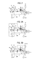
- FIG. 2 is a partially enlarged schematic diagram illustrating the transfer device 20A.
- the transfer device 20A includes a pressure roller 21 serving as a vibration suppression mechanism.
- the pressure roller 21 is disposed between the brush roller 12 and the photoreceptor 1Y, that is, downstream from the brush roller 12 in the direction of movement of the intermediate transfer belt 5, to press the intermediate transfer belt 5 from the outer surface thereof.
- the pressure roller 21 is disposed between the photoreceptor drum 1Y and the brush roller 12 to press the belt surface 5A of the intermediate transfer belt 5 so that tension is applied to the intermediate transfer belt 5 between the photoreceptor 1Y and the brush roller 12. Accordingly, vibration of the intermediate transfer belt 5 due to rotation of the brush roller 12 is suppressed, if not prevented entirely, thereby preventing transmission of the vibration to the photoreceptor drum 1Y and thus an abnormal image.
- FIGS. 3A is a partially enlarged schematic diagram illustrating the transfer device 20B including the pressure roller 21 and a voltage applicator 22 serving as a first voltage applicator that supplies the pressure roller 21 with a voltage.
- the polarity of the bias provided from the voltage applicator 22 to the pressure roller 21 is the same polarity as that of the toner.
- Supplying the bias to the pressure roller 21 can reduce the amount of press or movement of the pressure roller 21 as compared with supplying no bias to the pressure roller 21, thus reducing mechanical stress against the intermediate transfer belt 5 and resulting in extending the life of the intermediate transfer belt 5.
- the amount of press by the pressure roller 21 is relatively large, a force in a direction moving away from the photoreceptor drum acts on the primary transfer roller 9Y disposed upstream in the direction of movement of the intermediate transfer belt 5, causing the primary transfer roller 9Y to separate undesirably from the photoreceptor 1Y and thus fluctuations in a nip width and a nip pressure between the photoreceptor 1Y and the intermediate transfer belt 5.
- a power source dedicated for the voltage applicator 22 can be provided, Alternatively, however, as illustrated in FIG. 3A , the power source constituting the primary transfer bias applicator 16 may also serve as the voltage applicator 22. Furthermore, as illustrated in FIG. 3B , the power source constituting the secondary transfer bias applicator 18 may also serve as the voltage applicator 22. In this configuration, no power source dedicated for the voltage applicator 22 is needed, thereby reducing the cost as well as the size of the transfer device.
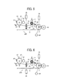
- FIGS. 5 is a partially enlarged schematic diagram illustrating the transfer device 20C including an opposing pressure roller 23.
- the opposing pressure roller 23 is disposed across from the pressure roller 21 through the intermediate transfer belt 5.
- the voltage applicator 22 supplies the pressure roller 21 with a voltage that causes the toner adhered to the pressure roller 21 to move toward the intermediate transfer belt 5.
- the opposing pressure roller 23 is disposed in the inner loop of the intermediate transfers belt 5 and connected to ground.
- the voltage applicator 22 applies alternately the voltages having polarities same as and different from the polarity of the toner to the pressure roller 21 with a predetermined timing, that is, after the image forming operation is finished, for example.
- the voltages having the polarity same as and different from that of the toner are hereinafter referred collectively to as a cleaning voltage (cleaning bias).
- the voltage applicator 22 applies alternately the voltages of negative and positive polarities (cleaning bias) to the pressure roller 21.
- the toner having different polarities adhering to the pressure roller 21 can be cleaned, thereby reducing, if not preventing entirely, the toner adhering to the pressure roller 21 from migrating onto the intermediate transfer belt 5 during the image forming operation.
- the voltage applicator 22 serves as a cleaning voltage application mechanism.
- the bias voltage that is, to initiate cleaning of the pressure roller 21, after a predetermined number of image forming operation is performed.
- the bias voltage be supplied (cleaning be initiated) after a predetermined cumulative number of image forming operation or a predetermined cumulative time elapses, and after a sequence of the image forming operation is finished.
- the pressure roller 21 is cleaned periodically, thus reducing, if not preventing entirely, generation of an abnormal image for an extended period of time.
- the pressure roller 21 is cleaned by supplying alternatively the voltages of the negative and the positive polarities thereto after the abnormal state is cancelled.
- FIGS. 6 is a partially enlarged schematic diagram illustrating the transfer device 20D including a voltage applicator 24 serving as a second voltage applicator that supplies the opposing pressure roller 23 with voltage.
- the polarity of bias is configured to be opposite the polarity of the toner.
- the opposing pressure roller 23 and the intermediate transfer belt 5 absorb each other electrostatically, thereby suppressing vibration of the intermediate transfer belt 5 easily. Since the polarity of the bias is opposite the polarity of the toner, it is made possible to generate an electric field that causes the toner to migrate from the pressure roller 21 to the opposing pressure roller 23. Accordingly, the toner sipping through the contact portion between the belt cleaning blade 10 and the intermediate transfer belt 5 is prevented from adhering to the pressure roller 21.
- FIGS. 7 is a partially enlarged schematic diagram illustrating the transfer device 20E in which the position of the pressure roller 21 is changeable from a position indicated by a broken line to a position indicated by a solid line.
- monochrome printing is performed frequently in the color image forming apparatus 100.
- the position of the primary transfer roller 9K for black is fixed while the rest of the primary transfer rollers 9Y, 9M, and 9C are separated from the corresponding photoreceptor drums 1Y, 1M, and 1C so that the primary transfer rollers 9Y, 9M, and 9C do not contact the photoreceptor drums 1Y, 1M, and 1C.
- the toner image in black is formed using the photoreceptor drum 1K.
- the transfer device 20E includes a moving device 90 that moves the pressure roller 21 from the position indicated by the broken line to the solid line while separating the primary transfer rollers 9Y, 9M, and 9C from the photoreceptor drums 1Y, 1M, and 1C.
- the moving device 90 includes a shaft 90a, a base plate 91, a spring 92, and a drive source, not illustrated.
- the base plate 91 is swingably disposed about the shaft 90a.
- the spring 92 urges the base plate 91 against the photoreceptor drums 1Y, 1M, and 1C.
- the drive source changes the position of the base plate 91 from the photoreceptor drum side to a position away from the photoreceptor drums (hereinafter referred to as a separating position).
- a motor and a gear mechanism may be employed as the drive source.
- an electromagnetic solenoid may be employed as the drive source.
- the primary transfer rollers 9Y, 9M, and 9C as well as the pressure roller 21 are provided to the base plate 91, thereby enabling the pressure roller 21 to move together with the primary transfer rollers 9Y, 9M, and 9C when the primary transfer rollers 9Y, 9M, and 9C separate from the photoreceptor drums 1Y, 1M, and 1C, thus causing the intermediate transfer belt 5 to separate from the photoreceptor drums 1Y, 1M, and 1C.
- the broken lines opposite the photoreceptor drums indicate a position when performing the full color image forming operation.
- the solid lines indicate a separating position when performing monochrome image forming operation (black).
- the drive source of the moving device 90 is operated so as to move the base plate 91 downward in FIG. 7 , thereby enabling the pressure roller 21 as well as the primary transfer rollers 9Y, 9M and 9C to move to the separating position illustrated in FIG. 8 .
- the primary transfer rollers 9Y, 9M and 9C are provided to the base plate 91 without the pressure roller 21 and the pressure roller 21 provided separately is urged downward in advance, it is still possible to separate the intermediate transfer belt 5 from the photoreceptors drums 1Y, 1M, and 1C by moving the primary transfer rollers 9Y, 9M and 9C.
- this configuration has a drawback. That is, because the pressure roller 21 is urged downward in advance, when forming a full color image, a significant force in the direction of the separating position, acts on the primary transfer roller 9Y, thereby moving undesirably the primary transfer roller 9Y away from the photoreceptor drum 1Y. As a result, the nip width and the nip pressure between the photoreceptor drum 1Y and the intermediate transfer belt 5 fluctuate undesirably.
- enabling the pressure roller 21 to move from the position of forming the full color image indicated by the broken line illustrated in FIG. 7 to the position of forming a monochrome image indicated by the solid line can minimize the pressing force of the pressure roller 21 relative to the belt surface 5A of the intermediate transfer belt 5, thereby stabilizing the nip width and the nip pressure between the photoreceptor drum 1 Y and the intermediate transfer belt 5.
- the pressure roller 21 is provided to the moving member 90 on which the primary rollers 9Y, 9M, and 9C are also provided so that the pressure roller 21 moves together with the primary rollers 9Y, 9M, and 9C.
- the moving mechanism is not limited to the above described configuration.
- the position of the shaft of the pressure roller 21 may be changeable such that the shaft thereof is supported movably by a frame of the transfer device or the image forming apparatus, and an arm member or a hook provided to the moving member 90 extending to the shaft of the pressure roller 21 engages the shaft. Accordingly, as the moving member 90 moves, the pressure roller 21 can move in conjunction with the moving member 90.
- the present invention is employed in the image forming apparatus.
- the image forming apparatus includes, but is not limited to, a copier, a printer, a facsimile machine, and a multi-functional system including at least two of these function.
- any one of the above-described and other exemplary features of the present invention may be embodied in the form of an apparatus, method, or system.
- any of the aforementioned methods may be embodied in the form of a system or device, including, but not limited to, any of the structure for performing the methodology illustrated in the drawings.
Landscapes
- Physics & Mathematics (AREA)
- General Physics & Mathematics (AREA)
- Electrostatic Charge, Transfer And Separation In Electrography (AREA)
- Color Electrophotography (AREA)
Abstract
Description
- Exemplary aspects of the present invention generally relate to a transfer device and an image forming apparatus, such as a copier, a facsimile machine, a printer, or a multi-functional system including a combination thereof, and more particularly, to a transfer device including a belt-type transfer member and an image forming apparatus including the transfer device.
- Conventionally, there is known a transfer device employed in, but not limited to, image forming apparatuses, such as copiers, printers, facsimile machines, and multifunctional systems including at least two of these functions, in which an endless looped belt is employed as an intermediate transfer member for transferring images.
- Typically, a color image forming apparatus is equipped with a plurality of cylindrical photoreceptors serving as image bearing members, one for each color, and a belt-type intermediate transfer member (hereinafter referred to as an intermediate transfer belt). The intermediate transfer belt is disposed across from and in contact with the photoreceptors which rotate at a certain speed, and rotates at the same peripheral speed as that of the photoreceptors.
- Such a color image forming apparatus equipped with the intermediate transfer belt includes also a developing device, a primary transfer device, and a secondary transfer device. The developing device develops latent images of different colors formed on the photoreceptors into toner images. The primary transfer device transfers overlappingly and sequentially the toner images formed on the photoreceptors onto the intermediate transfer belt, thereby forming a composite color toner image thereon. Then, the secondary transfer device transfers the composite color toner image from the intermediate transfer belt onto a transfer material, for example, a recording medium, thereby ultimately forming a color image.
- As the composite toner image is transferred from the intermediate transfer belt to the transfer material, it is not always the case that the toner of the composite toner image is transferred completely onto the transfer material. That is, undesirably, some residual toner remains on the intermediate transfer belt. Thus, a cleaning device, often constructed of a cleaning blade made of rubber or resin, is provided to clean the residual toner from the intermediate transfer belt. However, removal of the residual toner by the cleaning blade is becoming more difficult in recent years as toner consisting of very fine spherical particles increasingly comes to be used to satisfy growing market demand for the production of images of ever-higher quality.
- A conventional method of facilitating removal of residual toner employs a lubricant which is applied on the surface of the intermediate transfer belt to reduce adherence between the intermediate transfer belt and the residual toner. Generally, the lubricant is applied on the intermediate transfer belt using an application member, for example, a brush roller. The brush roller consists of a metal core around which a fabric with brush bristles is attached, thereby rubbing the lubricant retained on the brush bristles onto the intermediate transfer belt.
- Application of the lubricant is best accomplished in the absence of residual toner. Thus, the lubricant is usually applied to the intermediate transfer belt after the intermediate transfer belt is cleaned by the cleaning device.
- In such a conventional method, a roller (hereinafter referred to as an opposing roller) is disposed opposite the brush roller through the intermediate transfer belt (that is, on a side of the belt opposite the side on which the brush roller is disposed) to press the spanned surface of the intermediate transfer belt against the tip of the brush roller so that the tip of the brush roller can reliably contact the surface of the intermediate transfer belt while preventing rippling of the intermediate transfer belt as well. For example, the amount of the tip of the brush bristles of the brush roller engaging the belt surface is approximately 1 mm.
- Although advantageous, there is a drawback to this configuration in that, because the tip of the brush roller engages the belt surface to a depth of approximately 1 mm, the brush roller contacts not only the portion of the intermediate transfer belt contacting the opposing roller, but also other areas of the intermediate transfer belt not contacting the opposing roller, for example, areas adjacent to both ends of the contact area of the intermediate transfer belt with the opposing roller.
- As a result, when pressed by the tip of the brush roller, the portion of the intermediate transfer belt where the opposing roller does not contact the belt deforms under pressure from the brush. (By contrast, when pressed by the tip of the brush roller, the portion of the intermediate transfer belt contacting the opposing roller is prevented from being deformed.) When the tip of the brush roller separates from the intermediate transfer belt, the intermediate transfer belt flexes back to its original shape.
- As the brush roller repeatedly contacts and separates from the intermediate transfer belt, flexing the intermediate transfer belt continuously, rippling occurs in the intermediate transfer belt, thus resulting in undesirable vibration of the intermediate transfer belt. Such vibration hinders the intermediate transfer belt from reliably contacting the photoreceptors at their proper transfer positions, thus resulting in improper transfer of toner images. This improper transfer of the toner images may show up as banding in the resulting output image. In particular, when printing a halftone image, horizontal lines of narrow pitch appear in the image.
- While prevention of vibration of the intermediate transfer belt is of critical importance, in order to achieve desirable transfer performance it is generally desirable to wind around and stretch the intermediate transfer belt between two rollers so that the intermediate transfer belt can reliably contact the photoreceptors and primary transfer rollers serving as the primary transfer device at a constant pressure. However, increasing demand for making an image forming apparatus as compact as possible does not always allow for such a configuration.
- If the intermediate transfer belt is wound around the photoreceptors or the primary transfer rollers, the tension of the intermediate transfer belt causes the contact pressure between the photoreceptors and the primary transfer rollers to vary. This also results in improper transfer of the toner images.
- In view of the above, a device that can reduce, if not prevent entirely, vibration of the intermediate transfer belt is required while also making the transfer device as compact as possible.
- In view of the foregoing, in one illustrative embodiment of the present invention, a transfer device includes a pair of rollers, a rotatable intermediate transfer belt, a plurality of transfer members, a lubricant applicator, an opposing member, and a pressure member. The rotatable intermediate transfer belt is wound around and stretched between the pair of rollers to face a plurality of image bearing members for bearing toner images. Each of the plurality of transfer members faces a respective one of the plurality of the image bearing members through the intermediate transfer belt to transfer overlappingly the toner images onto the intermediate transfer belt to form a composite toner image thereon. The lubricant applicator is disposed upstream from the plurality of the image bearing members in a direction of rotation of the intermediate transfer belt and on the same plane on which the plurality of the image bearing members is disposed, to apply a lubricant to the intermediate transfer belt. The opposing member is disposed opposite the lubricant applicator through the intermediate transfer belt and contacts the intermediate transfer belt against the lubricant applicator. The pressure member is disposed upstream from the plurality of the image bearing members and downstream from the lubricant applicator in the direction of rotation of the intermediate transfer belt, to press against the intermediate transfer belt.
- In another illustrative embodiment of the present invention, an image forming apparatus includes a plurality of image bearing members, a developing device, and a transfer device. The plurality of image bearing members bears an electrostatic latent image on a surface thereof. The developing device develops the electrostatic latent images formed on the image bearing members using toner to form a toner image. The transfer device includes a pair of rollers, a rotatable intermediate transfer belt, a plurality of transfer members, a lubricant applicator, an opposing members, and a pressure member. The rotatable intermediate transfer belt is wound around and stretched between the pair of rollers to face a plurality of image bearing members for bearing toner images. Each of the plurality of transfer members faces a respective one of the plurality of the image bearing members through the intermediate transfer belt to transfer overlappingly the toner images onto the intermediate transfer belt to form a composite toner image thereon. The lubricant applicator is disposed upstream from the plurality of the image bearing members in a direction of rotation of the intermediate transfer belt and on the same plane on which the plurality of the image bearing members is disposed, to apply a lubricant to the intermediate transfer belt. The opposing member is disposed opposite the lubricant applicator through the intermediate transfer belt and contacts the intermediate transfer belt against the lubricant applicator. The pressure member is disposed upstream from the plurality of the image bearing members and downstream from the lubricant applicator in the direction of rotation of the intermediate transfer belt, to press against the intermediate transfer belt.
- Additional features and advantages of the present invention will be more fully apparent from the following detailed description of illustrative embodiments, the accompanying drawings and the associated claims.
- A more complete appreciation of the disclosure and many of the attendant advantages thereof will be readily obtained as the same becomes better understood by reference to the following detailed description of illustrative embodiments when considered in connection with the accompanying drawings, wherein:
-
FIG. 1 is a schematic diagram illustrating an image forming apparatus including a transfer device according to the illustrative embodiment of the present invention; -
FIG. 2 is a partially enlarged schematic diagram illustrating the transfer device according to a first illustrative embodiment of the present invention; -
FIGS. 3A and 3B are partially enlarged schematic diagrams illustrating the transfer device according to a second illustrative embodiment of the present invention; -
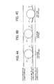
FIG. 4A is a schematic diagram illustrating a pressure member of the transfer device ofFIGS. 3A and 3B when applied with a bias; -
FIG. 4B is a schematic diagram illustrating the pressure member when no bias is applied; -
FIG. 4C is a schematic diagram illustrating the pressure member at which the pressure member attains a proper transfer area when no bias is applied; -
FIG. 5 is a partially enlarged schematic diagram illustrating a transfer device according to a third illustrative embodiment of the present invention; -
FIG. 6 is a partially enlarged schematic diagram illustrating a transfer device according to a fourth illustrative embodiment of the present invention; -
FIG. 7 is a partially enlarged schematic diagram illustrating a transfer device according to a fifth illustrative embodiment of the present invention; and -
FIG. 8 is an enlarged schematic diagram illustrating a moving device and the pressure member when moved by the moving device. - A description is now given of exemplary embodiments of the present invention. It should be noted that although such therms as first, second, etc. may be used herein to describe various elements, components, regions, layers and/or sections, it should be understood that such elements, components, regions, layers and/or sections are not limited thereby because such terms are relative, that is, used only to distinguish one element, component, region, layer or section from another region, layer or section. Thus, for example, a first element, component, region, layer or section discussed below could be termed a second element, component, region, layer or section without departing from the teachings of the present invention.
- In addition, it should be noted that the terminology used herein is for the purpose of describing particular embodiments only and is not intended to be limiting of the present invention. Thus, for example, as used herein, the singular forms "a", "an" and "the" are intended to include the plural forms as well, unless the context clearly indicates otherwise. Moreover, the terms "includes" and/or "including", when used in this specification, specify the presence of stated features, integers, steps, operations, elements, and/or components, but do not preclude the presence or addition of one or more other features, integers, steps, operations, elements, components, and/or groups thereof.
- In describing illustrative embodiments illustrated in the drawings, specific terminology is employed for the sake of clarity. However, the disclosure of this patent specification is not intended to be limited to the specific terminology so selected, and it is to be understood that each specific element includes all technical equivalents that operate in a similar manner and achieve a similar result.
- In a later-described comparative example, illustrative embodiment, and alternative example, for the sake of simplicity, the same reference numerals will be given to constituent elements such as parts and materials having the same functions, and redundant descriptions thereof omitted.
- Typically, but not necessarily, paper is the medium from which is made a sheet on which an image is to be formed. It should be noted, however, that other printable media are available in sheet form, and accordingly their use here is included. Thus, solely for simplicity, although this Detailed Description section refers to paper, sheets thereof, paper feeder, etc., it should be understood that the sheets, etc., are not limited only to paper, but includes other printable media as well.
- Referring now to the drawings, wherein like reference numerals designate identical or corresponding parts throughout the several views, and initially to
FIG. 1 , one example of an image forming apparatus according to an illustrative embodiment of the present invention is described. -
FIG. 1 is a schematic diagram illustrating a full-color printer as an example of animage forming apparatus 100 according to the illustrative embodiment can be employed. Theimage forming apparatus 100 includes, but is not limited to a printer, a copier, and a multifunctional system including at least two of these functions. - A
main body 101 of theimage forming apparatus 100 includes atransfer device 20, chargingdevices devices intermediate transfer belt 5 serving as an intermediate transfer device,cleaning blades photoreceptor drums - It is to be noted that reference characters Y, M, C, and K denote the colors yellow, magenta, cyan, and black, respectively.
- The
charging devices devices intermediate transfer belt 5, thecleaning blades respective photoreceptor drums - When forming a color image,
exposure light devices devices devices intermediate transfer belt 5, thereby forming a composite toner image. - The
intermediate transfer belt 5 is made of resin, and wound around and stretched between a pair of rollers, that is, a secondarytransfer opposing roller 7 and atension roller 8. When the secondarytransfer opposing roller 7 is driven by a drive motor M1, theintermediate transfer belt 5 is rotated in a counterclockwise direction indicated by an arrow. The photoreceptor drums 1Y, 1M, 1C, and 1K are arranged such that the photoreceptor drums 1Y, 1M, 1C, and 1K can contact abelt surface 5A of theintermediate transfer belt 5 stretched between a pair of roller, that is, the secondarytransfer opposing roller 7 and thetension roller 8. -
Primary transfer rollers intermediate transfer belt 5, facing each of the photoreceptor drums 1Y, 1M, 1C, and 1K, respectively. Each of theprimary transfer rollers intermediate transfer belt 5 by urging members such as a spring. - Each of the
primary transfer rollers FIG. 2 ) through a constant current control. - A tip of a
belt cleaning blade 10 serving as a cleaning member is pressed against thebelt surface 5A of theintermediate transfer belt 5 to clean residual toner, paper dust, and so forth adhered thereto. Thebelt cleaning blade 10 is formed of an elastic member such as urethane rubber or the like and disposed between the secondarytransfer opposing roller 7 and thephotoreceptor drum 1Y. Thebelt cleaning blade 10 is pressed against thebelt surface 5A at a position posterior to the secondary transfer process, thereby removing the substance such as residual toner from thebelt surface 5A. - In the inner loop of the
intermediate transfer belt 5, aroller 17 is disposed facing thebelt cleaning blade 10. In other words, theintermediate transfer belt 5 is sandwiched between theroller 17 and thebelt cleaning blade 10. - A
brush roller 12 is disposed between thephotoreceptor drum 1 Y and thebelt cleaning blade 10, that is, upstream from thephotoreceptor drum 1Y in the belt rotation direction, contactable relative to the belt surface. Thebrush roller 12 serves as a lubricant applicator that applies alubricant 11 onto the surface of theintermediate transfer belt 5. Thelubricant 11 includes, but is not limited to, fatty acid metal salts having a straight-chain hydrocarbon structure. Thebrush roller 12 consists of a metal core made of SUS or the like on which brush bristles made of polyester are adhered. - The direction of rotation of the
brush roller 12 coincides with the direction of movement of theintermediate transfer belt 5. Thebrush roller 12 is rotated by a drive motor, not illustrated, at a rotation speed 1.2 times the speed of movement of theintermediate transfer belt 5. - Since the
lubricant 11 is scraped by thebrush roller 12, thelubricant 11 is pressed against thebrush roller 12 by apressure member 111 such as an elastic member including, but not limited to, a spring. - An opposing
roller 13 formed of metal is disposed opposite thebrush roller 12 via theintermediate transfer belt 5. An amount of the tip of the brush bristles of thebrush roller 12 engaging the opposingroller 13 is configured to be approximately 1 mm. - A
secondary transfer roller 14 serving as a secondary transfer member is disposed opposite the secondarytransfer opposing roller 7 through theintermediate transfer belt 5. Thesecondary transfer roller 14 is driven by a drive gear, not illustrated. The secondarytransfer opposing roller 7 is supplied with a predetermined secondary transfer bias by a secondarytransfer bias applicator 18 through a constant current control. - As described above, according to the illustrative embodiment, the
transfer device 20 includes theintermediate transfer belt 5, theprimary transfer rollers belt cleaning blade 10, thebrush roller 12, the opposingroller 13, the primarytransfer bias applicator 16, and the secondarytransfer bias applicator 18. - In the
image forming apparatus 100, toner images of yellow, magenta, cyan, and black are formed by the developingdevices respective photoreceptors intermediate transfer belt 5 rotated by the drive motor M1 due to the primary transfer bias, thereby forming a composite toner image. - Subsequently, as the
intermediate transfer belt 5 bearing the composite toner image arrives at a secondary transfer position, the composite toner image is transferred onto a recording medium P conveyed from a sheet feeding unit, not illustrated. After the composite toner image is transferred onto the recording medium P, the recording medium P is conveyed to a fixingdevice 30 disposed downstream in the conveyance direction of the recording medium, where heat and pressure are applied to the composite toner image to fix it onto the recording medium P. Then, the recording medium P is discharged onto a sheet tray, not illustrated. - After the secondary transfer process, the
belt cleaning blade 10 removes the residual toner, paper powder, and so forth from the surface of theintermediate transfer belt 5. Then, thebrush roller 12 applies thelubricant 11 on theintermediate transfer belt 5 in preparation for the subsequent toner image transfer process. - In order to facilitate an understanding of the related art and of the novel features of the present invention, a description is provided of a mechanism that generates undesirable vibration when a lubricant is applied.
- Upon application of the
lubricant 11, thebrush roller 12 rotates opposite the opposingroller 13, generating undesirable vibration in theintermediate transfer belt 5. In a color image forming apparatus, vibration of theintermediate transfer belt 5 is transmitted to thephotoreceptor drum 1Y of yellow disposed immediately downstream from thebrush roller 12, causing banding in the toner image when the toner image is transferred from thephotoreceptor drum 1Y to theintermediate transfer belt 5. - In a case of the monochrome image forming apparatus, when the
brush roller 12 contacts theintermediate transfer belt 5 vibration of theintermediate transfer belt 5 is transferred to the photoreceptor of black. - In view of the foregoing, according to the illustrative embodiment, a vibration suppression mechanism is provided to the
transfer device 20 to reduce, if not prevent entirely, vibration of theintermediate transfer belt 5. - With reference to
FIG. 2 , a description is provided of atransfer device 20A including the vibration suppression mechanism according to a first illustrative embodiment.FIG. 2 is a partially enlarged schematic diagram illustrating thetransfer device 20A. - As illustrated in
FIG. 2 , thetransfer device 20A includes apressure roller 21 serving as a vibration suppression mechanism. Thepressure roller 21 is disposed between thebrush roller 12 and thephotoreceptor 1Y, that is, downstream from thebrush roller 12 in the direction of movement of theintermediate transfer belt 5, to press theintermediate transfer belt 5 from the outer surface thereof. - The
pressure roller 21 is disposed between thephotoreceptor drum 1Y and thebrush roller 12 to press thebelt surface 5A of theintermediate transfer belt 5 so that tension is applied to theintermediate transfer belt 5 between thephotoreceptor 1Y and thebrush roller 12. Accordingly, vibration of theintermediate transfer belt 5 due to rotation of thebrush roller 12 is suppressed, if not prevented entirely, thereby preventing transmission of the vibration to thephotoreceptor drum 1Y and thus an abnormal image. - With reference to
FIGS. 3A and 3B , a description is provided of atransfer device 20B according to a second illustrative embodiment.FIGS. 3A is a partially enlarged schematic diagram illustrating thetransfer device 20B including thepressure roller 21 and avoltage applicator 22 serving as a first voltage applicator that supplies thepressure roller 21 with a voltage. According to the present embodiment, the polarity of the bias provided from thevoltage applicator 22 to thepressure roller 21 is the same polarity as that of the toner. - Supplying the voltage (bias) to the
pressure roller 21 causes thepressure roller 21 and theintermediate transfer belt 5 to absorb electrostatically. An advantage of this configuration is that when thepressure roller 21 supplied with the voltage is pressed down by a certain amount relative to the lower surface of thephotoreceptor drum 1 as illustrated inFIG. 4B , an area of contact between thepressure roller 21 and theintermediate transfer belt 5 is greater than when thepressure roller 21 without the voltage is pressed by the same amount as illustrated inFIG. 4A . In other words, in order to obtain the same area of contact between thepressure roller 21 and theintermediate transfer belt 5 as that of when supplied with the voltage, thepressure roller 21 needs to be pressed further down (the pressure roller lower surface 2) as illustrated inFIG. 4C . - Supplying the bias to the
pressure roller 21 can reduce the amount of press or movement of thepressure roller 21 as compared with supplying no bias to thepressure roller 21, thus reducing mechanical stress against theintermediate transfer belt 5 and resulting in extending the life of theintermediate transfer belt 5. For example, if the amount of press by thepressure roller 21 is relatively large, a force in a direction moving away from the photoreceptor drum acts on theprimary transfer roller 9Y disposed upstream in the direction of movement of theintermediate transfer belt 5, causing theprimary transfer roller 9Y to separate undesirably from thephotoreceptor 1Y and thus fluctuations in a nip width and a nip pressure between thephotoreceptor 1Y and theintermediate transfer belt 5. - Furthermore, supplying the polarity same as that of the toner causes a repulsive force to act between the toner and the
pressure roller 21, thereby reducing, if not preventing entirely, the toner that slips through the contact portion between thebelt cleaning blade 10 and theintermediate transfer belt 5 from sticking to thepressure roller 21. - As a power source constituting the
voltage applicator 22, a power source dedicated for thevoltage applicator 22 can be provided, Alternatively, however, as illustrated inFIG. 3A , the power source constituting the primarytransfer bias applicator 16 may also serve as thevoltage applicator 22. Furthermore, as illustrated inFIG. 3B , the power source constituting the secondarytransfer bias applicator 18 may also serve as thevoltage applicator 22. In this configuration, no power source dedicated for thevoltage applicator 22 is needed, thereby reducing the cost as well as the size of the transfer device. - With reference to
FIG. 5 , a description is now provided of a transfer device 20C according to a third illustrative embodiment.FIGS. 5 is a partially enlarged schematic diagram illustrating the transfer device 20C including an opposingpressure roller 23. - As illustrated in
FIG. 5 , the opposingpressure roller 23 is disposed across from thepressure roller 21 through theintermediate transfer belt 5. - According to the present embodiment, the
voltage applicator 22 supplies thepressure roller 21 with a voltage that causes the toner adhered to thepressure roller 21 to move toward theintermediate transfer belt 5. The opposingpressure roller 23 is disposed in the inner loop of theintermediate transfers belt 5 and connected to ground. - According to the present embodiment, the
voltage applicator 22 applies alternately the voltages having polarities same as and different from the polarity of the toner to thepressure roller 21 with a predetermined timing, that is, after the image forming operation is finished, for example. The voltages having the polarity same as and different from that of the toner are hereinafter referred collectively to as a cleaning voltage (cleaning bias). Thevoltage applicator 22 applies alternately the voltages of negative and positive polarities (cleaning bias) to thepressure roller 21. - In this configuration, when supplying alternately the voltages of the positive and the negative polarities to the
pressure roller 21, the well-charged toner adhering to thepressure roller 21 migrates to theintermediate transfer belt 5 due to the voltage having the negative polarity. - In a case of the toner not fully charged, for example, the oppositely charged toner or low-charged toner adhering to the
pressure roller 21, such toner migrates to theintermediate transfer belt 5 when supplied with the voltage having the positive polarity. - By supplying alternately the voltage of the positive and the negative polarities to the
pressure roller 21, the toner having different polarities adhering to thepressure roller 21 can be cleaned, thereby reducing, if not preventing entirely, the toner adhering to thepressure roller 21 from migrating onto theintermediate transfer belt 5 during the image forming operation. In this configuration, thevoltage applicator 22 serves as a cleaning voltage application mechanism. - It is preferable to supply the bias voltage, that is, to initiate cleaning of the
pressure roller 21, after a predetermined number of image forming operation is performed. In other words, it is preferable that the bias voltage be supplied (cleaning be initiated) after a predetermined cumulative number of image forming operation or a predetermined cumulative time elapses, and after a sequence of the image forming operation is finished. - With this configuration., the
pressure roller 21 is cleaned periodically, thus reducing, if not preventing entirely, generation of an abnormal image for an extended period of time. - In a case in which an abnormal state such as paper jamming occurs during the image forming operation, the
pressure roller 21 is cleaned by supplying alternatively the voltages of the negative and the positive polarities thereto after the abnormal state is cancelled. With this configuration, even when a significant amount of toner remaining on theintermediate transfer belt 5 that has not been transferred onto the recording medium P due to the abnormal state of the image forming apparatus slips through the contact portion between thebelt cleaning blade 10 and theintermediate transfer belt 5 thus contaminating thepressure roller 21, the toner can be removed reliably from thepressure roller 21, thereby reducing, if not preventing entirely, generation of an abnormal image. - With reference to
FIG. 6 , a description is now provided of atransfer device 20D according to a fourth illustrative embodiment.FIGS. 6 is a partially enlarged schematic diagram illustrating thetransfer device 20D including avoltage applicator 24 serving as a second voltage applicator that supplies the opposingpressure roller 23 with voltage. The polarity of bias is configured to be opposite the polarity of the toner. - In this configuration, when the bias is supplied to the opposing
pressure roller 23, the opposingpressure roller 23 and theintermediate transfer belt 5 absorb each other electrostatically, thereby suppressing vibration of theintermediate transfer belt 5 easily. Since the polarity of the bias is opposite the polarity of the toner, it is made possible to generate an electric field that causes the toner to migrate from thepressure roller 21 to the opposingpressure roller 23. Accordingly, the toner sipping through the contact portion between thebelt cleaning blade 10 and theintermediate transfer belt 5 is prevented from adhering to thepressure roller 21. - With reference to
FIG. 7 , a description is now provided of atransfer device 20E according to a fifth illustrative embodiment.FIGS. 7 is a partially enlarged schematic diagram illustrating thetransfer device 20E in which the position of thepressure roller 21 is changeable from a position indicated by a broken line to a position indicated by a solid line. - Generally, monochrome printing is performed frequently in the color
image forming apparatus 100. When monochrome printing is performed in the colorimage forming apparatus 100, the position of theprimary transfer roller 9K for black is fixed while the rest of theprimary transfer rollers photoreceptor drums primary transfer rollers photoreceptor drum 1K. - In view of the foregoing, as illustrated in
FIG. 8 , thetransfer device 20E according to the present embodiment includes a movingdevice 90 that moves thepressure roller 21 from the position indicated by the broken line to the solid line while separating theprimary transfer rollers - As illustrated in
FIG. 8 , the movingdevice 90 includes ashaft 90a, abase plate 91, aspring 92, and a drive source, not illustrated. Thebase plate 91 is swingably disposed about theshaft 90a. Thespring 92 urges thebase plate 91 against the photoreceptor drums 1Y, 1M, and 1C. The drive source changes the position of thebase plate 91 from the photoreceptor drum side to a position away from the photoreceptor drums (hereinafter referred to as a separating position). A motor and a gear mechanism may be employed as the drive source. Alternatively, an electromagnetic solenoid may be employed as the drive source. - According to the present embodiment, the
primary transfer rollers pressure roller 21 are provided to thebase plate 91, thereby enabling thepressure roller 21 to move together with theprimary transfer rollers primary transfer rollers intermediate transfer belt 5 to separate from the photoreceptor drums 1Y, 1M, and 1C. - In both
FIGS. 7 and 8 , the broken lines opposite the photoreceptor drums indicate a position when performing the full color image forming operation. By contrast, the solid lines indicate a separating position when performing monochrome image forming operation (black). - When forming a monochrome image, the drive source of the moving
device 90 is operated so as to move thebase plate 91 downward inFIG. 7 , thereby enabling thepressure roller 21 as well as theprimary transfer rollers FIG. 8 . - If the
primary transfer rollers base plate 91 without thepressure roller 21 and thepressure roller 21 provided separately is urged downward in advance, it is still possible to separate theintermediate transfer belt 5 from the photoreceptors drums 1Y, 1M, and 1C by moving theprimary transfer rollers - However, although effective, this configuration has a drawback. That is, because the
pressure roller 21 is urged downward in advance, when forming a full color image, a significant force in the direction of the separating position, acts on theprimary transfer roller 9Y, thereby moving undesirably theprimary transfer roller 9Y away from thephotoreceptor drum 1Y. As a result, the nip width and the nip pressure between thephotoreceptor drum 1Y and theintermediate transfer belt 5 fluctuate undesirably. - By contrast, according to the illustrative embodiment, when forming a monochrome image, enabling the
pressure roller 21 to move from the position of forming the full color image indicated by the broken line illustrated inFIG. 7 to the position of forming a monochrome image indicated by the solid line can minimize the pressing force of thepressure roller 21 relative to thebelt surface 5A of theintermediate transfer belt 5, thereby stabilizing the nip width and the nip pressure between thephotoreceptor drum 1 Y and theintermediate transfer belt 5. - Furthermore, providing both the
pressure roller 21 and theprimary transfer rollers member 90, requires no dedicated moving member for moving thepressure roller 21, thereby reducing the cost and the size of the device. - As mentioned above, the
pressure roller 21 is provided to the movingmember 90 on which theprimary rollers pressure roller 21 moves together with theprimary rollers pressure roller 21 may be changeable such that the shaft thereof is supported movably by a frame of the transfer device or the image forming apparatus, and an arm member or a hook provided to the movingmember 90 extending to the shaft of thepressure roller 21 engages the shaft. Accordingly, as the movingmember 90 moves, thepressure roller 21 can move in conjunction with the movingmember 90. - According to the illustrative embodiment, the present invention is employed in the image forming apparatus. The image forming apparatus includes, but is not limited to, a copier, a printer, a facsimile machine, and a multi-functional system including at least two of these function.
- Furthermore, it is to be understood that elements and/or features of different illustrative embodiments may be combined with each other and/or substituted for each other within the scope of this disclosure and appended claims. In addition, the number of constituent elements, locations, shapes and so forth of the constituent elements are not limited to any of the structure for performing the methodology illustrated in the drawings.
- Still further, any one of the above-described and other exemplary features of the present invention may be embodied in the form of an apparatus, method, or system.
- For example, any of the aforementioned methods may be embodied in the form of a system or device, including, but not limited to, any of the structure for performing the methodology illustrated in the drawings.
- Example embodiments being thus described, it will be obvious that the same may be varied in many ways. Such exemplary variations are not to be regarded as a departure from the scope of the present invention, and all such modifications as would be obvious to one skilled in the art are intended to be included within the scope of the following claims.
- The present patent application is based on and claims priority from Japanese Patent Application No.
2009-206116 filed on September 7, 2009
Claims (15)
- A transfer device (20), comprising:a pair of rollers (7,8);a rotatable intermediate transfer belt (5) wound around and stretched between the pair of rollers to face a plurality of image bearing members (1K; 1C; 1M; 1Y) for bearing toner images;a plurality of transfer members (9K; 9C; 9M; 9Y), each facing a respective one of the plurality of the image bearing members through the intermediate transfer belt, to transfer overlappingly the toner images onto the intermediate transfer belt to form a composite toner image thereon;a lubricant applicator (12) disposed upstream from the plurality of the image bearing members (1K; 1C; 1M; 1Y) in a direction of rotation of the intermediate transfer belt and on the same plane on which the plurality of the image bearing members is disposed, to apply a lubricant (11) to the intermediate transfer belt;an opposing member (13) disposed opposite the lubricant applicator (12) through the intermediate transfer belt, to contact the intermediate transfer belt against the lubricant applicator; anda pressure member (21) disposed upstream from the plurality of the image bearing members and downstream from the lubricant applicator in the direction of rotation of the intermediate transfer belt, to press against the intermediate transfer belt.
- The transfer device according to claim 1, wherein the pressure member (21) presses against the outer circumference of the intermediate transfer belt (5).
- The transfer device according to claim 1 or 2 further comprising a first voltage applicator (22) that applies a voltage to the pressure member.
- The transfer device according to claim 3, wherein the voltage applied by the first voltage applicator (22) to the pressure member (21) has a polarity identical to that of the toner image on the image bearing members or of a developing agent.
- The transfer device according to claim 3 or 4, wherein the first voltage applicator (22) includes a power source.
- The transfer device according to claim 5, wherein the power source of the first voltage applicator (22) provides a transfer bias when transferring the toner images from the image bearing members (1K; 1C; 1M; 1Y) to the intermediate transfer belt (5).
- The transfer device according to claim 5, further comprising a secondary transfer member (14) that transfers the composite toner image from the intermediate transfer belt(5)onto a recording medium,
wherein the power source of the first voltage applicator (22) provides a secondary transfer bias to the secondary transfer member (14) when transferring the composite toner image from the intermediate transfer belt(5) to the recording medium. - The transfer device according to claim 3, wherein the first voltage applicator (22) applies a cleaning voltage to the pressure member (21) between image forming operations to move residual toner adhering to the pressure member to the intermediate transfer belt (5).
- The transfer device according to claim 8, wherein the first voltage applicator (22) applies the voltage to the pressure member (21) after a threshold number of image forming operations is performed.
- The transfer device according to claim 8, wherein the voltage applicator applies (22) the voltage to the pressure member (21) after a certain cumulative operating time elapses.
- The transfer device according to claim 8, wherein the first voltage applicator (22) applies the cleaning voltage to the pressure member (21) after correction of a malfunction during an image forming operation.
- The transfers device according to claim 1 or 2, further comprising:an opposing pressure member (23) disposed opposite the pressure member (21) through the intermediate transfer belt (5); anda second voltage applicator (24) to apply a voltage having a polarity opposite the polarity of the toner of the toner image or of a developing agent to the opposing pressure member (23).
- The transfer device according to any one of preceding claims, further comprising:a moving device (90) that separates all but one of the transfer members (9K; 9C; 9M; 9Y) from the respective image bearing members (1K; 1C; 1M; 1Y),
wherein, when the moving device separates the transfer members from the image bearing members, the pressure member is moved so as to separate the intermediate transfer belt from the image bearing members. - The transfers device according to claim 13, wherein the moving device (90) moves the pressure member (21).
- An image forming apparatus, comprising:a plurality of image bearing members (1K; 1C; 1M; 1Y) to bear an electrostatic latent image on a surface thereof;a plurality of developing devices (4K; 4C; 4M; 4Y) to develop the electrostatic latent images formed on the image bearing members using toner to form a toner image; anda transfer device (20) including
a pair of rollers (7, 8);
a rotatable intermediate transfer belt (5) wound around and stretched between the pair of rollers to face the plurality of image bearing members of the image forming apparatus;
a plurality of transfer members (9K; 9C; 9M; 9Y), each facing a respective one of the plurality of the image bearing members (1K; 1C; 1M; 1Y) through the intermediate transfer belt (5), to transfer overlappingly the toner images onto the intermediate transfer belt to form a composite toner image on the intermediate transfer belt;
a lubricant applicator (12) disposed upstream from the plurality of the image bearing members in a direction of rotation of the intermediate transfer belt and on the same plane on which the plurality of the image bearing members is disposed, to apply a lubricant (11) to the intermediate transfer belt;
an opposing member (13) disposed opposite the lubricant applicator (12) to
contact the intermediate transfer belt (5) against the lubricant applicator; anda pressure member (21) disposed upstream from the plurality of the image bearing members and downstream from the lubricant applicator in the direction of rotation of the intermediate transfer belt, to press against the intermediate transfer belt (5).
Applications Claiming Priority (1)
| Application Number | Priority Date | Filing Date | Title |
|---|---|---|---|
| JP2009206116A JP5493608B2 (en) | 2009-09-07 | 2009-09-07 | Transfer device and image forming apparatus |
Publications (2)
| Publication Number | Publication Date |
|---|---|
| EP2296052A2 true EP2296052A2 (en) | 2011-03-16 |
| EP2296052A3 EP2296052A3 (en) | 2014-12-03 |
Family
ID=43334485
Family Applications (1)
| Application Number | Title | Priority Date | Filing Date |
|---|---|---|---|
| EP10175009.9A Withdrawn EP2296052A3 (en) | 2009-09-07 | 2010-09-02 | Transfer device and image forming apparatus including same |
Country Status (4)
| Country | Link |
|---|---|
| US (1) | US8457536B2 (en) |
| EP (1) | EP2296052A3 (en) |
| JP (1) | JP5493608B2 (en) |
| CN (1) | CN102012659B (en) |
Cited By (2)
| Publication number | Priority date | Publication date | Assignee | Title |
|---|---|---|---|---|
| EP2735912A3 (en) * | 2012-11-26 | 2017-10-25 | Kyocera Document Solutions Inc. | Transfer device and image forming apparatus including the same |
| EP3121657B1 (en) * | 2015-07-24 | 2020-08-26 | Kyocera Document Solutions Inc. | Image forming apparatus |
Families Citing this family (45)
| Publication number | Priority date | Publication date | Assignee | Title |
|---|---|---|---|---|
| JP2012234004A (en) * | 2011-04-28 | 2012-11-29 | Konica Minolta Business Technologies Inc | Lubricant application device and image forming apparatus |
| JP2013019950A (en) * | 2011-07-07 | 2013-01-31 | Ricoh Co Ltd | Belt device, and image forming apparatus |
| JP6047956B2 (en) | 2011-08-22 | 2016-12-21 | 株式会社リコー | Image forming apparatus |
| JP5915244B2 (en) | 2012-02-21 | 2016-05-11 | 株式会社リコー | Image forming apparatus |
| US9643403B2 (en) | 2012-03-05 | 2017-05-09 | Landa Corporation Ltd. | Printing system |
| US11104123B2 (en) | 2012-03-05 | 2021-08-31 | Landa Corporation Ltd. | Digital printing system |
| US9498946B2 (en) | 2012-03-05 | 2016-11-22 | Landa Corporation Ltd. | Apparatus and method for control or monitoring of a printing system |
| EP2822778B1 (en) | 2012-03-05 | 2019-05-08 | Landa Corporation Ltd. | Digital printing process |
| US11809100B2 (en) | 2012-03-05 | 2023-11-07 | Landa Corporation Ltd. | Intermediate transfer members for use with indirect printing systems and protonatable intermediate transfer members for use with indirect printing systems |
| BR112014021786B1 (en) | 2012-03-05 | 2021-06-08 | Landa Corporation Ltd | paint film structures |
| US9517618B2 (en) | 2012-03-15 | 2016-12-13 | Landa Corporation Ltd. | Endless flexible belt for a printing system |
| US9351425B2 (en) * | 2013-04-24 | 2016-05-24 | Hitachi Systems, Ltd. | Container-type data center |
| WO2014174607A1 (en) * | 2013-04-24 | 2014-10-30 | 株式会社日立システムズ | Container-type data center provided with air-conditioning apparatus |
| JP6317549B2 (en) * | 2013-06-10 | 2018-04-25 | コニカミノルタ株式会社 | Image forming apparatus |
| JP2016027353A (en) | 2013-08-22 | 2016-02-18 | 株式会社リコー | Image forming apparatus |
| GB201401173D0 (en) | 2013-09-11 | 2014-03-12 | Landa Corp Ltd | Ink formulations and film constructions thereof |
| JP6394151B2 (en) | 2014-03-18 | 2018-09-26 | 株式会社リコー | Belt unit, transfer unit and image forming apparatus |
| JP2016038568A (en) | 2014-08-08 | 2016-03-22 | 株式会社リコー | Image forming apparatus |
| JP6417840B2 (en) * | 2014-10-08 | 2018-11-07 | 株式会社リコー | Transfer device and image forming apparatus |
| GB2536489B (en) | 2015-03-20 | 2018-08-29 | Landa Corporation Ltd | Indirect printing system |
| GB2537813A (en) | 2015-04-14 | 2016-11-02 | Landa Corp Ltd | Apparatus for threading an intermediate transfer member of a printing system |
| JP6512951B2 (en) * | 2015-06-03 | 2019-05-15 | キヤノン株式会社 | Belt device and image forming apparatus |
| GB201609463D0 (en) | 2016-05-30 | 2016-07-13 | Landa Labs 2012 Ltd | Method of manufacturing a multi-layer article |
| JP6980704B2 (en) | 2016-05-30 | 2021-12-15 | ランダ コーポレイション リミテッド | Digital printing process |
| DE112017002714T5 (en) * | 2016-05-30 | 2019-02-28 | Landa Corporation Ltd. | Digital printing process |
| JP6888285B2 (en) | 2016-12-06 | 2021-06-16 | 株式会社リコー | Transfer device and image forming device |
| CN111212736B (en) | 2017-10-19 | 2021-11-23 | 兰达公司 | Endless flexible belt for a printing system |
| WO2019097464A1 (en) | 2017-11-19 | 2019-05-23 | Landa Corporation Ltd. | Digital printing system |
| US11511536B2 (en) | 2017-11-27 | 2022-11-29 | Landa Corporation Ltd. | Calibration of runout error in a digital printing system |
| US11707943B2 (en) | 2017-12-06 | 2023-07-25 | Landa Corporation Ltd. | Method and apparatus for digital printing |
| US11679615B2 (en) | 2017-12-07 | 2023-06-20 | Landa Corporation Ltd. | Digital printing process and method |
| IL279556B2 (en) | 2018-06-26 | 2024-06-01 | Landa Corp Ltd | An intermediate transfer member for a digital printing system |
| US10994528B1 (en) | 2018-08-02 | 2021-05-04 | Landa Corporation Ltd. | Digital printing system with flexible intermediate transfer member |
| US12001902B2 (en) | 2018-08-13 | 2024-06-04 | Landa Corporation Ltd. | Correcting distortions in digital printing by implanting dummy pixels in a digital image |
| US11318734B2 (en) | 2018-10-08 | 2022-05-03 | Landa Corporation Ltd. | Friction reduction means for printing systems and method |
| CN113272144B (en) | 2018-12-24 | 2023-04-04 | 兰达公司 | Digital printing system and method |
| WO2020202145A1 (en) | 2019-03-31 | 2020-10-08 | Landa Corporation Ltd | Systems and methods for preventing or minimizing printing defects in printing processes |
| WO2021105806A1 (en) | 2019-11-25 | 2021-06-03 | Landa Corporation Ltd. | Drying ink in digital printing using infrared radiation absorbed by particles embedded inside itm |
| US11321028B2 (en) | 2019-12-11 | 2022-05-03 | Landa Corporation Ltd. | Correcting registration errors in digital printing |
| CN114868087A (en) | 2019-12-29 | 2022-08-05 | 兰达公司 | Printing method and system |
| JP7419828B2 (en) | 2020-01-17 | 2024-01-23 | 株式会社リコー | Roller unit, belt device, and image forming device |
| US11494602B2 (en) | 2020-09-15 | 2022-11-08 | Ricoh Company, Ltd. | Image forming apparatus |
| JP2024506561A (en) | 2021-02-02 | 2024-02-14 | ランダ コーポレイション リミテッド | Reduce distortion in printed images |
| JP2022158083A (en) | 2021-04-01 | 2022-10-14 | 株式会社リコー | Image forming apparatus |
| JP7761870B2 (en) | 2021-08-31 | 2025-10-29 | 株式会社リコー | Pressing force adjusting device, transfer device and image forming apparatus |
Family Cites Families (22)
| Publication number | Priority date | Publication date | Assignee | Title |
|---|---|---|---|---|
| DE19813697C2 (en) * | 1997-03-31 | 2001-05-31 | Ricoh Kk | Imaging device with intermediate transfer element |
| CN1268990C (en) | 2001-01-05 | 2006-08-09 | 佳能株式会社 | Procedure for producing trip transferrer, trip transferrer and imaging apparatus |
| JP2003029550A (en) * | 2001-07-13 | 2003-01-31 | Ricoh Co Ltd | Image forming device |
| JP2004102123A (en) * | 2002-09-12 | 2004-04-02 | Matsushita Electric Ind Co Ltd | Color image forming device |
| JP2007248931A (en) * | 2006-03-17 | 2007-09-27 | Ricoh Co Ltd | Image forming apparatus |
| JP5005310B2 (en) * | 2006-10-05 | 2012-08-22 | 株式会社リコー | Lubricant coating apparatus, process cartridge, and image forming apparatus |
| JP4798786B2 (en) * | 2006-11-10 | 2011-10-19 | 株式会社リコー | Belt device and image forming apparatus |
| JP2008139799A (en) * | 2006-12-05 | 2008-06-19 | Ricoh Co Ltd | Lubricant coating apparatus, cleaning apparatus, image forming apparatus, and image forming method |
| JP2008242347A (en) * | 2007-03-29 | 2008-10-09 | Ricoh Co Ltd | Image forming apparatus |
| US20090035038A1 (en) * | 2007-08-03 | 2009-02-05 | Naomi Sugimoto | Cleaning device, image carrier unit, and image forming apparatus |
| JP5151339B2 (en) * | 2007-09-14 | 2013-02-27 | 株式会社リコー | Image forming apparatus |
| JP5037292B2 (en) * | 2007-10-09 | 2012-09-26 | 株式会社リコー | Cleaning device, image carrier unit, and image forming apparatus |
| JP5102142B2 (en) * | 2008-04-15 | 2012-12-19 | 株式会社リコー | Powder container, cleaning device, and image forming apparatus |
| JP2009300860A (en) * | 2008-06-16 | 2009-12-24 | Ricoh Co Ltd | Cleaning device and image forming apparatus |
| JP2010014943A (en) * | 2008-07-03 | 2010-01-21 | Ricoh Co Ltd | Cleaning device, image forming apparatus, and process cartridge |
| US7979000B2 (en) * | 2008-07-04 | 2011-07-12 | Ricoh Company Limited | Transfer unit and image forming apparatus |
| EP2144123B1 (en) * | 2008-07-08 | 2016-10-19 | Ricoh Company, Ltd. | Transfer Unit and Image Forming Apparatus Employing the Transfer Unit |
| JP2010020026A (en) * | 2008-07-09 | 2010-01-28 | Ricoh Co Ltd | Cleaning device and image forming apparatus |
| JP2010044123A (en) * | 2008-08-08 | 2010-02-25 | Ricoh Co Ltd | Polarity controller, cleaner, image forming apparatus, multicolor image forming apparatus, and process cartridge |
| JP5505759B2 (en) * | 2008-09-17 | 2014-05-28 | 株式会社リコー | Image forming apparatus |
| JP5158508B2 (en) * | 2008-09-30 | 2013-03-06 | 株式会社リコー | Image forming apparatus |
| JP5493406B2 (en) * | 2009-03-17 | 2014-05-14 | 株式会社リコー | Cleaning device, process cartridge, and image forming apparatus |
-
2009
- 2009-09-07 JP JP2009206116A patent/JP5493608B2/en active Active
-
2010
- 2010-09-01 CN CN201010271325.5A patent/CN102012659B/en active Active
- 2010-09-01 US US12/923,090 patent/US8457536B2/en not_active Expired - Fee Related
- 2010-09-02 EP EP10175009.9A patent/EP2296052A3/en not_active Withdrawn
Non-Patent Citations (1)
| Title |
|---|
| None |
Cited By (2)
| Publication number | Priority date | Publication date | Assignee | Title |
|---|---|---|---|---|
| EP2735912A3 (en) * | 2012-11-26 | 2017-10-25 | Kyocera Document Solutions Inc. | Transfer device and image forming apparatus including the same |
| EP3121657B1 (en) * | 2015-07-24 | 2020-08-26 | Kyocera Document Solutions Inc. | Image forming apparatus |
Also Published As
| Publication number | Publication date |
|---|---|
| CN102012659A (en) | 2011-04-13 |
| CN102012659B (en) | 2013-03-27 |
| JP5493608B2 (en) | 2014-05-14 |
| US8457536B2 (en) | 2013-06-04 |
| US20110058859A1 (en) | 2011-03-10 |
| JP2011059189A (en) | 2011-03-24 |
| EP2296052A3 (en) | 2014-12-03 |
Similar Documents
| Publication | Publication Date | Title |
|---|---|---|
| US8457536B2 (en) | Transfer device and image forming apparatus including same | |
| JP7362029B2 (en) | Cleaning device, belt device, and image forming device | |
| US7672605B2 (en) | Transfer device and image forming apparatus | |
| JP6071497B2 (en) | Image forming apparatus | |
| US9152099B2 (en) | Fixing device, image forming apparatus, and fixing method | |
| US7684732B2 (en) | Process unit and image forming apparatus including the same | |
| JP5304631B2 (en) | Image forming apparatus | |
| JP5040639B2 (en) | Image forming apparatus | |
| US10379463B2 (en) | Transfer unit and image forming apparatus | |
| US20120237251A1 (en) | Image forming apparatus | |
| JP5109733B2 (en) | Image forming apparatus | |
| JP2009109573A (en) | Image forming apparatus | |
| JP2005309181A (en) | Intermediate transfer unit | |
| JPH08137183A (en) | Color image forming device | |
| JP2012168314A (en) | Image forming apparatus | |
| US7970319B2 (en) | Charging apparatus, print engine that incorporates the charging apparatus, and image forming apparatus that incorporates the print engine | |
| JP2011141377A (en) | Cleaning device and image forming apparatus | |
| JP2007078759A (en) | Image forming apparatus | |
| JP5545538B2 (en) | Transfer device and image forming apparatus | |
| JP2006235395A (en) | Image forming apparatus | |
| JP5099022B2 (en) | Image forming apparatus | |
| JP2008058437A (en) | Transfer device and image forming apparatus | |
| JP2017026724A (en) | Image forming apparatus | |
| JP2013238892A (en) | Cleaning member, cleaning device, process cartridge and image forming apparatus | |
| JP2021081517A (en) | Cleaning device and image forming apparatus |
Legal Events
| Date | Code | Title | Description |
|---|---|---|---|
| PUAI | Public reference made under article 153(3) epc to a published international application that has entered the european phase |
Free format text: ORIGINAL CODE: 0009012 |
|
| AK | Designated contracting states |
Kind code of ref document: A2 Designated state(s): AL AT BE BG CH CY CZ DE DK EE ES FI FR GB GR HR HU IE IS IT LI LT LU LV MC MK MT NL NO PL PT RO SE SI SK SM TR |
|
| AX | Request for extension of the european patent |
Extension state: BA ME RS |
|
| RIC1 | Information provided on ipc code assigned before grant |
Ipc: G03G 15/01 20060101AFI20140701BHEP Ipc: G03G 15/16 20060101ALI20140701BHEP |
|
| PUAL | Search report despatched |
Free format text: ORIGINAL CODE: 0009013 |
|
| AK | Designated contracting states |
Kind code of ref document: A3 Designated state(s): AL AT BE BG CH CY CZ DE DK EE ES FI FR GB GR HR HU IE IS IT LI LT LU LV MC MK MT NL NO PL PT RO SE SI SK SM TR |
|
| AX | Request for extension of the european patent |
Extension state: BA ME RS |
|
| RIC1 | Information provided on ipc code assigned before grant |
Ipc: G03G 15/01 20060101AFI20141027BHEP Ipc: G03G 15/16 20060101ALI20141027BHEP |
|
| 17P | Request for examination filed |
Effective date: 20150121 |
|
| RBV | Designated contracting states (corrected) |
Designated state(s): AL AT BE BG CH CY CZ DE DK EE ES FI FR GB GR HR HU IE IS IT LI LT LU LV MC MK MT NL NO PL PT RO SE SI SK SM TR |
|
| 17Q | First examination report despatched |
Effective date: 20160802 |
|
| GRAP | Despatch of communication of intention to grant a patent |
Free format text: ORIGINAL CODE: EPIDOSNIGR1 |
|
| INTG | Intention to grant announced |
Effective date: 20161005 |
|
| STAA | Information on the status of an ep patent application or granted ep patent |
Free format text: STATUS: THE APPLICATION IS DEEMED TO BE WITHDRAWN |
|
| 18D | Application deemed to be withdrawn |
Effective date: 20170216 |