EP2296030B1 - Method for printing a stereograph and related print device - Google Patents
Method for printing a stereograph and related print device Download PDFInfo
- Publication number
- EP2296030B1 EP2296030B1 EP09016064.9A EP09016064A EP2296030B1 EP 2296030 B1 EP2296030 B1 EP 2296030B1 EP 09016064 A EP09016064 A EP 09016064A EP 2296030 B1 EP2296030 B1 EP 2296030B1
- Authority
- EP
- European Patent Office
- Prior art keywords
- region
- ribbon
- dye
- print medium
- Prior art date
- Legal status (The legal status is an assumption and is not a legal conclusion. Google has not performed a legal analysis and makes no representation as to the accuracy of the status listed.)
- Not-in-force
Links
- 238000000034 method Methods 0.000 title claims description 23
- 239000000975 dye Substances 0.000 claims description 49
- 239000000463 material Substances 0.000 claims description 9
- 238000012546 transfer Methods 0.000 claims description 8
- 238000004519 manufacturing process Methods 0.000 claims description 6
- AJDUTMFFZHIJEM-UHFFFAOYSA-N n-(9,10-dioxoanthracen-1-yl)-4-[4-[[4-[4-[(9,10-dioxoanthracen-1-yl)carbamoyl]phenyl]phenyl]diazenyl]phenyl]benzamide Chemical group O=C1C2=CC=CC=C2C(=O)C2=C1C=CC=C2NC(=O)C(C=C1)=CC=C1C(C=C1)=CC=C1N=NC(C=C1)=CC=C1C(C=C1)=CC=C1C(=O)NC1=CC=CC2=C1C(=O)C1=CC=CC=C1C2=O AJDUTMFFZHIJEM-UHFFFAOYSA-N 0.000 claims description 5
- 239000001043 yellow dye Substances 0.000 claims description 5
- 239000007779 soft material Substances 0.000 claims description 3
- 238000010586 diagram Methods 0.000 description 6
- 230000003287 optical effect Effects 0.000 description 5
- 238000004026 adhesive bonding Methods 0.000 description 3
- 238000007796 conventional method Methods 0.000 description 3
- 238000013461 design Methods 0.000 description 3
- 230000007246 mechanism Effects 0.000 description 3
- 238000012545 processing Methods 0.000 description 3
- 239000004743 Polypropylene Substances 0.000 description 2
- 239000004433 Thermoplastic polyurethane Substances 0.000 description 2
- 229920000728 polyester Polymers 0.000 description 2
- 229920001155 polypropylene Polymers 0.000 description 2
- 239000010802 sludge Substances 0.000 description 2
- 238000000859 sublimation Methods 0.000 description 2
- 230000008022 sublimation Effects 0.000 description 2
- 229920002803 thermoplastic polyurethane Polymers 0.000 description 2
- 210000004556 brain Anatomy 0.000 description 1
- 230000001419 dependent effect Effects 0.000 description 1
- 238000011161 development Methods 0.000 description 1
- 230000018109 developmental process Effects 0.000 description 1
- 239000003292 glue Substances 0.000 description 1
- 238000003384 imaging method Methods 0.000 description 1
- -1 polypropylene Polymers 0.000 description 1
- 239000004800 polyvinyl chloride Substances 0.000 description 1
Images


Classifications
-
- B—PERFORMING OPERATIONS; TRANSPORTING
- B29—WORKING OF PLASTICS; WORKING OF SUBSTANCES IN A PLASTIC STATE IN GENERAL
- B29D—PRODUCING PARTICULAR ARTICLES FROM PLASTICS OR FROM SUBSTANCES IN A PLASTIC STATE
- B29D11/00—Producing optical elements, e.g. lenses or prisms
- B29D11/00009—Production of simple or compound lenses
- B29D11/00278—Lenticular sheets
-
- G—PHYSICS
- G03—PHOTOGRAPHY; CINEMATOGRAPHY; ANALOGOUS TECHNIQUES USING WAVES OTHER THAN OPTICAL WAVES; ELECTROGRAPHY; HOLOGRAPHY
- G03B—APPARATUS OR ARRANGEMENTS FOR TAKING PHOTOGRAPHS OR FOR PROJECTING OR VIEWING THEM; APPARATUS OR ARRANGEMENTS EMPLOYING ANALOGOUS TECHNIQUES USING WAVES OTHER THAN OPTICAL WAVES; ACCESSORIES THEREFOR
- G03B35/00—Stereoscopic photography
- G03B35/14—Printing apparatus specially adapted for conversion between different types of record
Definitions
- the present invention relates to a method for printing a stereograph and a printing device according to the pre-characterizing clauses of claims 1 and 9.
- a stereograph can transfer a viewer's view angle from two-dimensional space into three-dimensional space, so as to restore a scene with depth of field on the stereograph and to improve a sense of reality of the scene.
- the viewer can distinguish a distance and a depth of the scene on the stereograph.
- Method for producing three-dimensional vision utilizes parallax theory, such as adjusting radian of eyes for changing focal lengths of the eyes and adjusting view angles of the eyes. Because the stereograph shows images having different angles and distances on two eyes of the viewer, respectively, parallax is generated between the images viewed by the two eyes, and the images can be analyzed to generate the three-dimensional vision in the viewer's brain.
- Stereoscopic imaging technique includes holographic images, grating images, lens images, and so on.
- a method of applying an optical grating structure to image the stereograph is easier than other methods, and is utilized widespread.
- there are two types of common methods for generating the stereograph One conventional method is printing the images processed by stereographic image processing technique on a back of the optical grating structure directly.
- the other conventional method is printing the images processed by the stereographic image processing technique on a common print medium, and then gluing the optical grating structure on the common print medium.
- process of gluing the optical grating structure on the print medium is complicated, spends working hours, and needs numerous glue to fix the optical grating structure on the print medium.
- the conventional methods print the stereograph slowly and increase manufacturing cost.
- design of a stereograph printing mechanism capable of printing the stereograph rapidly and having low cost is an important issue in the printing industry.
- the present invention aims at providing a method for printing a stereograph and a printing device.
- the claimed method includes manufacturing a lenticular lens structure on a surface of a protecting region of a ribbon wherein the ribbon comprises a plurality of dye regions and the protecting region; receiving a target image datum; conveying a print medium; transferring the plurality of dye regions of the ribbon onto the print medium respectively according to the target image datum when conveying the print medium; and transferring the protecting region of the ribbon onto the print medium after transferring the plurality of dye regions of the ribbon onto the print medium.
- FIG.1 is a diagram of a print device 10 according to a preferred embodiment of the present invention.
- the print device 10 can be a dye sublimation printer for printing a stereograph.
- the print device 10 includes an actuating unit 12 for moving a print medium 14.
- the actuating unit 12 can include a plurality of driving mechanisms, such as a motor, a roller, and so on.
- the print device 10 further includes a ribbon 16.
- the ribbon 16 includes a plurality of dye regions 18 and a protecting region 20.
- the protecting region 20 is made of high transparency material, and the protecting region 20 further can be made of protecting material having waterproof function, oilproof function, or anti-UV function, so as to prevent the dye regions from being oozed, faded, or polluted by moisture or oil sludge.
- a lenticular lens structure 22 is formed on a surface of the protecting region 20.
- the print device 10 further includes a thermal print head 24 for transferring the plurality of dye regions 18 and the protecting region 20 of the ribbon 16 onto the print medium 14, respectively, and a control unit 26 coupled to the actuating unit 12 and the thermal print head 24 for controlling the actuating unit 12 to move the print medium 14 according to a target image datum and for controlling the thermal print head 24 to transfer the plurality of dye regions 18 and the protecting region 20 of the ribbon 16 onto the print medium 14, respectively.
- the target image datum is processed by stereographic image technique.
- the target image datum can be an interlaced image datum.
- the interlaced image datum can be a set of images that is generated by photographing a scene at different view angles and is recorded on the print medium 14 with stripes.
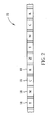
- FIG.2 is a diagram of the ribbon 16 according to the preferred embodiment of the present invention.
- the ribbon 16 includes the plurality of dye regions 18 and the protecting region 20.
- the plurality of dye regions 18 can include a yellow dye region Y, a magenta dye region M, a cyan dye region C, and a black dye region K.
- the plurality of dye regions 18 and the protecting region 20 are arranged on the ribbon 16 alternately.
- the plurality of dye regions 18 can be selected from a group consisting of the yellow dye region Y, the magenta dye region M, the cyan dye region C, the black dye region K, and combination thereof.
- the plurality of dye regions 18 is not limited to the above-mentioned embodiment and depends on actual demand.
- the protecting region 20 can be made of soft material, such as polyvinyl chloride (PVC), thermoplastic polyurethane (TPU), and so on.
- the protecting region 20 can further be made of hard material, such as polyester (PET), polypropylene (PP), and so on. Material of the protecting region 20 is not limited to the above-mentioned embodiment and depends on actual demand.
- the plurality of dye regions 18 and the protecting region 20 of the ribbon 16 can be transferred on the print medium 14 in a thermal sublimated manner.
- FIG.3 is a diagram of the protecting region 20 according the preferred embodiment of the present invention.
- the lenticular lens structure 22 is formed on the surface of the protecting region 20 for inflecting light so as to show different images in different view angles.
- the lenticular lens structure 22 can be made of high transparency material.
- a plurality of semi-cylindrical structures is formed on a side of the lenticular lens structure 22, and an intact plane is formed on the other side of the lenticular lens structure 22. Distances between the plurality of semi-cylindrical structures of the lenticular lens structure 22 are equal so as to transmit the light reflected from the stereograph on the print medium 14 uniformly.
- the lenticular lens structure 22 can be a narrow angle lenticular lens structure or a wide angle lenticular lens structure.
- the narrow angle lenticular lens structure is suitable to the stereograph having depth of field, and a view angle of the narrow angle lenticular lens structure is substantially between 15 degrees and 44 degrees preferably.
- the wide angle lenticular lens structure is suitable to a bivariant image, and view angle of the wide angle lenticular lens structure is substantially between 44 degrees and 65 degrees preferably. Selection and structure of the lenticular lens structure 22 are not limited to the above-mentioned embodiment and depend on design demand.
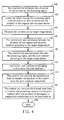
- FIG.4 is a flow chart for printing the stereograph according to the preferred embodiment of the present invention.
- the printing method includes following steps: Step 100: Manufacture the lenticular lens structure 22 on the surface of the protecting region 20; Step 102: Install the ribbon 16 having the protecting region 20 with the lenticular lens structure 22 and the plurality of dye regions 18 into the print device 10; Step 104: The print device 10 receives the target image datum wherein the target image datum can be the interlaced image datum; Step 106: The control unit 26 sets correlation between the plurality of dye regions 18 of the ribbon 16 and the print medium 14 according to the target image datum; Step 108: The control unit 26 sets correlation between the protecting region 20 of the ribbon 16 and the print medium 14 according to the target image datum; Step 110: The control unit 26 controls the actuating unit 12 to move the print medium 14; Step 112: The control unit 26 controls the thermal print head 24 to transfer the plurality of dye regions 18 of the ribbon 16 onto the print medium 14, respectively, according to the target image
- the lenticular lens structure 22 is manufactured on the surface of the protecting region 20 before the stereograph is printed. Because the protecting region 20 is made of high transparency material with waterproof function, oilproof function, and anti UV function, the ribbon 16 also has protecting function and grating function when manufacturing the lenticular lens structure 22 on the surface of the protecting region 20, so that a user can print the stereograph by a common print device 10, such as the dye sublimation printer, rapidly and simply. Material and view angles of the lenticular lens structure 22 depend on actual design demand. Then, the user installs the ribbon 16 including the protecting region 20 whereon the lenticular lens structure 22 is manufactured and the plurality of dye regions 18 inside the print device 10, and the print device 10 can start to print the stereograph.
- the control unit 26 of the print device 10 receives the target image datum processed by stereographic image processing, and sets the correlation between the plurality of dye regions 18 of the ribbon 16 and the print medium 14 and the correlation between the protecting region 20 of the ribbon 16 and the print medium 14 according to the target image datum, respectively.
- the control unit 26 controls the actuating unit 12 to move the print medium 14 in a predetermined speed and controls the thermal print head 24 to transfer the plurality of dye regions 18 including the yellow dye region Y, the magenta dye region M, the cyan dye region C, the black dye region K onto corresponding positions of the print medium 14 moving in the predetermined speed according to the set correlation, so as to generate the stereograph.
- the control unit 26 can control the thermal print head 24 to transfer the protecting region 20 onto the corresponding positions of the print medium 14 whereon the stereograph is printed according to the set correlation, which means the protecting region 20 covers on the stereograph. Therefore, the protecting region 20 can prevent the stereograph from being oozed, faded, or polluted by moisture or oil sludge.
- the view can view the stereograph via the protecting region 20 whereon the lenticular lens structure 22 is manufactured so as to generate the three-dimensional image.
- the print device of the present invention can utilize the common print device to print the stereograph, and does not additionally set a glued mechanism for gluing the lenticular lens structure on the print medium.
- the lenticular lens structure is manufactured on the protecting region of the conventional ribbon in the present invention, and the protecting region whereon the lenticular lens structure is manufactured is transferred onto the print medium, so as to generate the stereograph. Therefore, the present invention can decrease printing time, economize printing cost, and improve operating convenience, effectively.
Landscapes
- Engineering & Computer Science (AREA)
- Health & Medical Sciences (AREA)
- Manufacturing & Machinery (AREA)
- Ophthalmology & Optometry (AREA)
- Mechanical Engineering (AREA)
- Physics & Mathematics (AREA)
- General Physics & Mathematics (AREA)
- Electronic Switches (AREA)
- Impression-Transfer Materials And Handling Thereof (AREA)
- Thermal Transfer Or Thermal Recording In General (AREA)
Description
- The present invention relates to a method for printing a stereograph and a printing device according to the pre-characterizing clauses of claims 1 and 9.
- A stereograph can transfer a viewer's view angle from two-dimensional space into three-dimensional space, so as to restore a scene with depth of field on the stereograph and to improve a sense of reality of the scene. Thus, the viewer can distinguish a distance and a depth of the scene on the stereograph. Method for producing three-dimensional vision utilizes parallax theory, such as adjusting radian of eyes for changing focal lengths of the eyes and adjusting view angles of the eyes. Because the stereograph shows images having different angles and distances on two eyes of the viewer, respectively, parallax is generated between the images viewed by the two eyes, and the images can be analyzed to generate the three-dimensional vision in the viewer's brain. Stereoscopic imaging technique includes holographic images, grating images, lens images, and so on. A method of applying an optical grating structure to image the stereograph is easier than other methods, and is utilized widespread. Generally, there are two types of common methods for generating the stereograph. One conventional method is printing the images processed by stereographic image processing technique on a back of the optical grating structure directly. The other conventional method is printing the images processed by the stereographic image processing technique on a common print medium, and then gluing the optical grating structure on the common print medium. However, process of gluing the optical grating structure on the print medium is complicated, spends working hours, and needs numerous glue to fix the optical grating structure on the print medium. The conventional methods print the stereograph slowly and increase manufacturing cost. Thus, design of a stereograph printing mechanism capable of printing the stereograph rapidly and having low cost is an important issue in the printing industry.
- This in mind, the present invention aims at providing a method for printing a stereograph and a printing device.
- This is achieved by a method for printing a stereograph and a printing device according to claims 1 and 9. The dependent claims pertain to corresponding further developments and improvements.
- As will be seen more clearly from the detailed description following below, the claimed method includes manufacturing a lenticular lens structure on a surface of a protecting region of a ribbon wherein the ribbon comprises a plurality of dye regions and the protecting region; receiving a target image datum; conveying a print medium; transferring the plurality of dye regions of the ribbon onto the print medium respectively according to the target image datum when conveying the print medium; and transferring the protecting region of the ribbon onto the print medium after transferring the plurality of dye regions of the ribbon onto the print medium.
- In the following, the invention is further illustrated by way of example, taking reference to the accompanying drawings. Thereof:
-
FIG.1 is a diagram of a print device according to a preferred embodiment of the present invention, -
FIG.2 is a diagram of a ribbon according to the preferred embodiment of the present invention, -
FIG.3 is a diagram of a protecting region according the preferred embodiment of the present invention, and -
FIG.4 is a flow chart for printing a stereograph according the preferred embodiment of the present invention. - Please refer to
FIG.1. FIG.1 is a diagram of aprint device 10 according to a preferred embodiment of the present invention. Theprint device 10 can be a dye sublimation printer for printing a stereograph. Theprint device 10 includes an actuatingunit 12 for moving aprint medium 14. The actuatingunit 12 can include a plurality of driving mechanisms, such as a motor, a roller, and so on. Theprint device 10 further includes aribbon 16. Theribbon 16 includes a plurality ofdye regions 18 and a protectingregion 20. The protectingregion 20 is made of high transparency material, and the protectingregion 20 further can be made of protecting material having waterproof function, oilproof function, or anti-UV function, so as to prevent the dye regions from being oozed, faded, or polluted by moisture or oil sludge. Alenticular lens structure 22 is formed on a surface of the protectingregion 20. Theprint device 10 further includes athermal print head 24 for transferring the plurality ofdye regions 18 and the protectingregion 20 of theribbon 16 onto theprint medium 14, respectively, and acontrol unit 26 coupled to the actuatingunit 12 and thethermal print head 24 for controlling the actuatingunit 12 to move theprint medium 14 according to a target image datum and for controlling thethermal print head 24 to transfer the plurality ofdye regions 18 and the protectingregion 20 of theribbon 16 onto theprint medium 14, respectively. The target image datum is processed by stereographic image technique. The target image datum can be an interlaced image datum. For example, the interlaced image datum can be a set of images that is generated by photographing a scene at different view angles and is recorded on theprint medium 14 with stripes. - Please refer to
FIG.2. FIG.2 is a diagram of theribbon 16 according to the preferred embodiment of the present invention. Theribbon 16 includes the plurality ofdye regions 18 and the protectingregion 20. The plurality ofdye regions 18 can include a yellow dye region Y, a magenta dye region M, a cyan dye region C, and a black dye region K. The plurality ofdye regions 18 and the protectingregion 20 are arranged on theribbon 16 alternately. The plurality ofdye regions 18 can be selected from a group consisting of the yellow dye region Y, the magenta dye region M, the cyan dye region C, the black dye region K, and combination thereof. The plurality ofdye regions 18 is not limited to the above-mentioned embodiment and depends on actual demand. The protectingregion 20 can be made of soft material, such as polyvinyl chloride (PVC), thermoplastic polyurethane (TPU), and so on. The protectingregion 20 can further be made of hard material, such as polyester (PET), polypropylene (PP), and so on. Material of the protectingregion 20 is not limited to the above-mentioned embodiment and depends on actual demand. In addition, the plurality ofdye regions 18 and the protectingregion 20 of theribbon 16 can be transferred on theprint medium 14 in a thermal sublimated manner. - Please refer to
FIG.3. FIG.3 is a diagram of the protectingregion 20 according the preferred embodiment of the present invention. Thelenticular lens structure 22 is formed on the surface of the protectingregion 20 for inflecting light so as to show different images in different view angles. Thelenticular lens structure 22 can be made of high transparency material. A plurality of semi-cylindrical structures is formed on a side of thelenticular lens structure 22, and an intact plane is formed on the other side of thelenticular lens structure 22. Distances between the plurality of semi-cylindrical structures of thelenticular lens structure 22 are equal so as to transmit the light reflected from the stereograph on theprint medium 14 uniformly. Thelenticular lens structure 22 can be a narrow angle lenticular lens structure or a wide angle lenticular lens structure. Generally, the narrow angle lenticular lens structure is suitable to the stereograph having depth of field, and a view angle of the narrow angle lenticular lens structure is substantially between 15 degrees and 44 degrees preferably. The wide angle lenticular lens structure is suitable to a bivariant image, and view angle of the wide angle lenticular lens structure is substantially between 44 degrees and 65 degrees preferably. Selection and structure of thelenticular lens structure 22 are not limited to the above-mentioned embodiment and depend on design demand. - Please refer to
FIG.4. FIG.4 is a flow chart for printing the stereograph according to the preferred embodiment of the present invention. The printing method includes following steps:Step 100: Manufacture the lenticular lens structure 22 on the surface of the protectingregion 20;Step 102: Install the ribbon 16 having the protectingregion 20 with thelenticular lens structure 22 and the plurality ofdye regions 18 into theprint device 10;Step 104: The print device 10 receives the target image datum wherein the target image datum can be the interlaced image datum;Step 106: The control unit 26 sets correlation between the plurality ofdye regions 18 of theribbon 16 and theprint medium 14 according to the target image datum;Step 108: The control unit 26 sets correlation between the protectingregion 20 of theribbon 16 and theprint medium 14 according to the target image datum;Step 110: The control unit 26 controls the actuatingunit 12 to move theprint medium 14;Step 112: The control unit 26 controls thethermal print head 24 to transfer the plurality ofdye regions 18 of theribbon 16 onto theprint medium 14, respectively, according to the target image datum when theprint medium 14 is moved;Step 114: The control unit 26 controls thethermal print head 24 to transfer the protectingregions 20 of theribbon 16 onto theprint medium 14 according to the target image datum after thecontrol unit 26 controls thethermal print head 24 to transfer the plurality ofdye regions 18 of theribbon 16 onto theprint medium 14;Step 116: End. - A detailed description of the printing method is introduced as following. First, the
lenticular lens structure 22 is manufactured on the surface of the protectingregion 20 before the stereograph is printed. Because the protectingregion 20 is made of high transparency material with waterproof function, oilproof function, and anti UV function, theribbon 16 also has protecting function and grating function when manufacturing thelenticular lens structure 22 on the surface of the protectingregion 20, so that a user can print the stereograph by acommon print device 10, such as the dye sublimation printer, rapidly and simply. Material and view angles of thelenticular lens structure 22 depend on actual design demand. Then, the user installs theribbon 16 including the protectingregion 20 whereon thelenticular lens structure 22 is manufactured and the plurality ofdye regions 18 inside theprint device 10, and theprint device 10 can start to print the stereograph. - First, the
control unit 26 of theprint device 10 receives the target image datum processed by stereographic image processing, and sets the correlation between the plurality ofdye regions 18 of theribbon 16 and theprint medium 14 and the correlation between the protectingregion 20 of theribbon 16 and theprint medium 14 according to the target image datum, respectively. After that, thecontrol unit 26 controls theactuating unit 12 to move theprint medium 14 in a predetermined speed and controls thethermal print head 24 to transfer the plurality ofdye regions 18 including the yellow dye region Y, the magenta dye region M, the cyan dye region C, the black dye region K onto corresponding positions of theprint medium 14 moving in the predetermined speed according to the set correlation, so as to generate the stereograph. However, a viewer can not view a three-dimensional image by directly watching the stereograph only with the plurality ofdye regions 18. Thus, thecontrol unit 26 can control thethermal print head 24 to transfer the protectingregion 20 onto the corresponding positions of theprint medium 14 whereon the stereograph is printed according to the set correlation, which means the protectingregion 20 covers on the stereograph. Therefore, the protectingregion 20 can prevent the stereograph from being oozed, faded, or polluted by moisture or oil sludge. In addition, the view can view the stereograph via the protectingregion 20 whereon thelenticular lens structure 22 is manufactured so as to generate the three-dimensional image. - Comparing to the prior art, the print device of the present invention can utilize the common print device to print the stereograph, and does not additionally set a glued mechanism for gluing the lenticular lens structure on the print medium. The lenticular lens structure is manufactured on the protecting region of the conventional ribbon in the present invention, and the protecting region whereon the lenticular lens structure is manufactured is transferred onto the print medium, so as to generate the stereograph. Therefore, the present invention can decrease printing time, economize printing cost, and improve operating convenience, effectively.
Claims (15)
- A method for printing a stereograph comprising:receiving a target image datum;conveying a print medium (14);characterized in that the method further comprises:manufacturing a lenticular lens structure (22) on a surface of a protecting region (20) of a ribbon (16) wherein the ribbon (16) comprises a plurality of dye regions (18) and the protecting region (20);transferring the plurality of dye regions (18) of the ribbon (16) onto the print medium (14) respectively according to the target image datum when conveying the print medium (14); andtransferring the protecting region (20) of the ribbon (16) onto the print medium (14) after transferring the plurality of dye regions (18) of the ribbon (16) onto the print medium (14).
- The method of claim 1 characterized by:setting a correlation between the plurality of dye regions (18) of the ribbon (16) and the print medium (14) according to the target image datum.
- The method of claim 1 or 2 characterized by:setting a correlation between the protecting region (20) of the ribbon (16) and the print medium (14) according to the target image datum.
- The method of any one of claims 1 to 3, characterized in that receiving the target image datum comprises receiving an interlaced image datum.
- The method of any one of claims 1 to 4, characterized in that the plurality of dye regions (18) comprises a yellow dye region, a magenta dye region, a cyan dye region, and a black dye region.
- The method of any one of claims 1 to 5, characterized in that the lenticular lens structure (22) is a narrow angle lenticular lens structure or a wide angle lenticular structure.
- The method of any one of claims 1 to 6, characterized in that the protecting region (20) is made of soft material or hard material.
- The method of any one of claims 1 to 7, characterized in that the plurality of dye regions (18) and the protecting region (20) of the ribbon (16) are transferred onto the print medium (14) in a thermal sublimated manner.
- A print device (10) comprising:an actuating unit (12) for conveying a print medium (14);characterized in that the print device (10) further comprises:a ribbon (16) comprising a plurality of dye regions (18) and a protecting region (20), a lenticular lens structure (22) being formed on a surface of the protecting region (20);a thermal print head (24) for transferring the plurality of dye regions (18) and the protecting region (20) of the ribbon (16) onto the print medium (14), respectively; anda control unit (26) coupled to the actuating unit (12) and the thermal print head (24) for controlling the actuating unit (12) to convey the print medium (14) according to a target image datum and for controlling the thermal print head (24) to transfer the plurality of dye regions (18) and the protecting region (20) of the ribbon (16) onto the print medium (14), respectively.
- The print device (10) of claim 9, characterized in that the control unit (26) is for setting a correlation between the plurality of dye regions (18) of the ribbon (16) and the print medium (14) according to the target image datum.
- The print device (10) of claim 9 or 10, characterized in that the control unit (26) is for setting a correlation between the protecting region (20) of the ribbon (16) and the print medium (14) according to the target image datum.
- The print device (10) of any one of claims 9 or 11, characterized in that the target image datum is an interlaced image datum.
- The print device (10) of any one of claims 9 to 12, characterized in that the plurality of dye regions (18) comprises a yellow dye region, a magenta dye region, a cyan dye region, and a black dye region.
- The print device (10) of any one of claims 9 to 13, characterized in that the lenticular lens structure (22) is a narrow angle lenticular lens structure or a wide angle lenticular structure.
- The print device (10) of any one of claims 9 to 14, characterized in that the protecting region (20) is made of soft material or hard material.
Applications Claiming Priority (1)
| Application Number | Priority Date | Filing Date | Title |
|---|---|---|---|
| TW098130523A TWI357857B (en) | 2009-09-10 | 2009-09-10 | Method for printing a stereograph and related prin |
Publications (2)
| Publication Number | Publication Date |
|---|---|
| EP2296030A1 EP2296030A1 (en) | 2011-03-16 |
| EP2296030B1 true EP2296030B1 (en) | 2014-02-26 |
Family
ID=42112091
Family Applications (1)
| Application Number | Title | Priority Date | Filing Date |
|---|---|---|---|
| EP09016064.9A Not-in-force EP2296030B1 (en) | 2009-09-10 | 2009-12-28 | Method for printing a stereograph and related print device |
Country Status (3)
| Country | Link |
|---|---|
| US (1) | US8212848B2 (en) |
| EP (1) | EP2296030B1 (en) |
| TW (1) | TWI357857B (en) |
Families Citing this family (1)
| Publication number | Priority date | Publication date | Assignee | Title |
|---|---|---|---|---|
| TWI473725B (en) * | 2012-09-28 | 2015-02-21 | Hiti Digital Inc | Printing device for printing a stereograph and related method |
Family Cites Families (13)
| Publication number | Priority date | Publication date | Assignee | Title |
|---|---|---|---|---|
| CA2089093C (en) | 1991-06-12 | 1997-02-25 | Sung Lee | Recording and reproducing a 3-dimensional image |
| JPH06278318A (en) * | 1993-03-29 | 1994-10-04 | Sony Corp | Printing equipment |
| JP3409810B2 (en) * | 1993-09-09 | 2003-05-26 | ソニー株式会社 | Image output method |
| TW236641B (en) | 1994-04-27 | 1994-12-21 | Ind Tech Res Inst | |
| JP3310858B2 (en) * | 1995-05-11 | 2002-08-05 | 松下電器産業株式会社 | Apparatus for printing image data |
| JP3352879B2 (en) * | 1995-11-10 | 2002-12-03 | 松下電器産業株式会社 | Image recording apparatus, image data recording method, and lenticular sheet |
| JPH11109530A (en) | 1997-10-07 | 1999-04-23 | Toppan Printing Co Ltd | How to create stereoscopic images |
| US6712536B2 (en) * | 2001-10-09 | 2004-03-30 | Alps Electric Co., Ltd. | Printer |
| TWI236641B (en) | 2001-12-18 | 2005-07-21 | I Art Corp | Method for fast and automatically producing lenticular lens image for two(multiple) flips, motions, and 3D pictures |
| TW558669B (en) | 2002-07-19 | 2003-10-21 | Shr-Ping Chen | 3D imaging system and operation method thereof |
| JP2006240202A (en) | 2005-03-07 | 2006-09-14 | Sanyo Electric Co Ltd | Ribbon for printing device, printing device using the ribbon, and ribbon type detecting method |
| TWM286113U (en) | 2005-08-10 | 2006-01-21 | Sun Sui Print Co Ltd | 3D image structure for random point light grid |
| TW200810519A (en) | 2006-08-01 | 2008-02-16 | Tong-Yin Qiu | Image-forming method to convert a 2D image into a 3D image |
-
2009
- 2009-09-10 TW TW098130523A patent/TWI357857B/en not_active IP Right Cessation
- 2009-11-10 US US12/616,082 patent/US8212848B2/en not_active Expired - Fee Related
- 2009-12-28 EP EP09016064.9A patent/EP2296030B1/en not_active Not-in-force
Also Published As
| Publication number | Publication date |
|---|---|
| US8212848B2 (en) | 2012-07-03 |
| TW201109186A (en) | 2011-03-16 |
| EP2296030A1 (en) | 2011-03-16 |
| US20110058007A1 (en) | 2011-03-10 |
| TWI357857B (en) | 2012-02-11 |
Similar Documents
| Publication | Publication Date | Title |
|---|---|---|
| US6133928A (en) | Image recording apparatus, image data generating apparatus, and recording method | |
| EP1191384A2 (en) | Diagonal lenticular image system | |
| US20160077350A1 (en) | System And Method For Lenticular Image Printing And Print Media | |
| EP0619513B1 (en) | Apparatus and method for aligning images of a film member to a lenticular member | |
| US8624945B1 (en) | Printing device for printing a stereograph and related method | |
| KR102221773B1 (en) | Three dimensional image display device | |
| EP1424609A3 (en) | Color shift correcting method, optical writing device and image forming apparatus | |
| US6992693B2 (en) | Display apparatus | |
| WO2005025238A3 (en) | Sweet spot beam splitter for separating images | |
| US8472117B2 (en) | Lens array and 3-dimensional display apparatus including the same | |
| US20180232866A1 (en) | Vehicle display comprising projection system | |
| US8212848B2 (en) | Method for printing a stereograph and related print device | |
| US20170008302A1 (en) | Printer, printing system, and card manufacturing method | |
| CN102019778B (en) | Method for printing stereoscopic photos and related printing device | |
| US20150092268A1 (en) | Image display apparatus | |
| JPH04136836A (en) | Stereoscopic image forming device | |
| US20110228236A1 (en) | Printing apparatus | |
| CN109752856B (en) | Digital microfluidic device, manufacturing method, naked-eye three-dimensional display device and display method | |
| CN1278075A (en) | Stereoscopic camera | |
| JP5508749B2 (en) | Stereoscopic image printing device | |
| US20130062009A1 (en) | Three-dimensional image output apparatus | |
| CN109791473A (en) | Prepare the image for printing | |
| JPH07281328A (en) | Lenticular print media | |
| KR100950346B1 (en) | Apparatus for three-dimension display panel manufacturing and manufacturing method thereof | |
| Hayashishita et al. | P‐43: A Head‐Up Display with Time‐Division Multiplexing Parallax Barrier with Magnified Virtual Image Generation |
Legal Events
| Date | Code | Title | Description |
|---|---|---|---|
| PUAI | Public reference made under article 153(3) epc to a published international application that has entered the european phase |
Free format text: ORIGINAL CODE: 0009012 |
|
| AK | Designated contracting states |
Kind code of ref document: A1 Designated state(s): AT BE BG CH CY CZ DE DK EE ES FI FR GB GR HR HU IE IS IT LI LT LU LV MC MK MT NL NO PL PT RO SE SI SK SM TR |
|
| AX | Request for extension of the european patent |
Extension state: AL BA RS |
|
| 17P | Request for examination filed |
Effective date: 20110420 |
|
| RIC1 | Information provided on ipc code assigned before grant |
Ipc: G03B 35/14 20060101ALI20130702BHEP Ipc: G03B 35/18 20060101ALI20130702BHEP Ipc: G02B 27/22 20060101AFI20130702BHEP Ipc: G03B 35/24 20060101ALI20130702BHEP |
|
| GRAJ | Information related to disapproval of communication of intention to grant by the applicant or resumption of examination proceedings by the epo deleted |
Free format text: ORIGINAL CODE: EPIDOSDIGR1 |
|
| GRAP | Despatch of communication of intention to grant a patent |
Free format text: ORIGINAL CODE: EPIDOSNIGR1 |
|
| INTG | Intention to grant announced |
Effective date: 20130916 |
|
| INTG | Intention to grant announced |
Effective date: 20130924 |
|
| GRAS | Grant fee paid |
Free format text: ORIGINAL CODE: EPIDOSNIGR3 |
|
| GRAA | (expected) grant |
Free format text: ORIGINAL CODE: 0009210 |
|
| AK | Designated contracting states |
Kind code of ref document: B1 Designated state(s): AT BE BG CH CY CZ DE DK EE ES FI FR GB GR HR HU IE IS IT LI LT LU LV MC MK MT NL NO PL PT RO SE SI SK SM TR |
|
| REG | Reference to a national code |
Ref country code: GB Ref legal event code: FG4D |
|
| REG | Reference to a national code |
Ref country code: CH Ref legal event code: EP |
|
| REG | Reference to a national code |
Ref country code: AT Ref legal event code: REF Ref document number: 653921 Country of ref document: AT Kind code of ref document: T Effective date: 20140315 |
|
| REG | Reference to a national code |
Ref country code: IE Ref legal event code: FG4D |
|
| REG | Reference to a national code |
Ref country code: DE Ref legal event code: R096 Ref document number: 602009021954 Country of ref document: DE Effective date: 20140410 |
|
| REG | Reference to a national code |
Ref country code: NL Ref legal event code: VDEP Effective date: 20140226 |
|
| REG | Reference to a national code |
Ref country code: AT Ref legal event code: MK05 Ref document number: 653921 Country of ref document: AT Kind code of ref document: T Effective date: 20140226 |
|
| REG | Reference to a national code |
Ref country code: LT Ref legal event code: MG4D |
|
| PG25 | Lapsed in a contracting state [announced via postgrant information from national office to epo] |
Ref country code: LT Free format text: LAPSE BECAUSE OF FAILURE TO SUBMIT A TRANSLATION OF THE DESCRIPTION OR TO PAY THE FEE WITHIN THE PRESCRIBED TIME-LIMIT Effective date: 20140226 Ref country code: NO Free format text: LAPSE BECAUSE OF FAILURE TO SUBMIT A TRANSLATION OF THE DESCRIPTION OR TO PAY THE FEE WITHIN THE PRESCRIBED TIME-LIMIT Effective date: 20140526 Ref country code: IS Free format text: LAPSE BECAUSE OF FAILURE TO SUBMIT A TRANSLATION OF THE DESCRIPTION OR TO PAY THE FEE WITHIN THE PRESCRIBED TIME-LIMIT Effective date: 20140626 |
|
| PG25 | Lapsed in a contracting state [announced via postgrant information from national office to epo] |
Ref country code: PT Free format text: LAPSE BECAUSE OF FAILURE TO SUBMIT A TRANSLATION OF THE DESCRIPTION OR TO PAY THE FEE WITHIN THE PRESCRIBED TIME-LIMIT Effective date: 20140626 Ref country code: NL Free format text: LAPSE BECAUSE OF FAILURE TO SUBMIT A TRANSLATION OF THE DESCRIPTION OR TO PAY THE FEE WITHIN THE PRESCRIBED TIME-LIMIT Effective date: 20140226 Ref country code: CY Free format text: LAPSE BECAUSE OF FAILURE TO SUBMIT A TRANSLATION OF THE DESCRIPTION OR TO PAY THE FEE WITHIN THE PRESCRIBED TIME-LIMIT Effective date: 20140226 Ref country code: AT Free format text: LAPSE BECAUSE OF FAILURE TO SUBMIT A TRANSLATION OF THE DESCRIPTION OR TO PAY THE FEE WITHIN THE PRESCRIBED TIME-LIMIT Effective date: 20140226 Ref country code: FI Free format text: LAPSE BECAUSE OF FAILURE TO SUBMIT A TRANSLATION OF THE DESCRIPTION OR TO PAY THE FEE WITHIN THE PRESCRIBED TIME-LIMIT Effective date: 20140226 Ref country code: SE Free format text: LAPSE BECAUSE OF FAILURE TO SUBMIT A TRANSLATION OF THE DESCRIPTION OR TO PAY THE FEE WITHIN THE PRESCRIBED TIME-LIMIT Effective date: 20140226 |
|
| PG25 | Lapsed in a contracting state [announced via postgrant information from national office to epo] |
Ref country code: BE Free format text: LAPSE BECAUSE OF FAILURE TO SUBMIT A TRANSLATION OF THE DESCRIPTION OR TO PAY THE FEE WITHIN THE PRESCRIBED TIME-LIMIT Effective date: 20140226 Ref country code: HR Free format text: LAPSE BECAUSE OF FAILURE TO SUBMIT A TRANSLATION OF THE DESCRIPTION OR TO PAY THE FEE WITHIN THE PRESCRIBED TIME-LIMIT Effective date: 20140226 Ref country code: LV Free format text: LAPSE BECAUSE OF FAILURE TO SUBMIT A TRANSLATION OF THE DESCRIPTION OR TO PAY THE FEE WITHIN THE PRESCRIBED TIME-LIMIT Effective date: 20140226 |
|
| PG25 | Lapsed in a contracting state [announced via postgrant information from national office to epo] |
Ref country code: DK Free format text: LAPSE BECAUSE OF FAILURE TO SUBMIT A TRANSLATION OF THE DESCRIPTION OR TO PAY THE FEE WITHIN THE PRESCRIBED TIME-LIMIT Effective date: 20140226 Ref country code: CZ Free format text: LAPSE BECAUSE OF FAILURE TO SUBMIT A TRANSLATION OF THE DESCRIPTION OR TO PAY THE FEE WITHIN THE PRESCRIBED TIME-LIMIT Effective date: 20140226 Ref country code: RO Free format text: LAPSE BECAUSE OF FAILURE TO SUBMIT A TRANSLATION OF THE DESCRIPTION OR TO PAY THE FEE WITHIN THE PRESCRIBED TIME-LIMIT Effective date: 20140226 Ref country code: EE Free format text: LAPSE BECAUSE OF FAILURE TO SUBMIT A TRANSLATION OF THE DESCRIPTION OR TO PAY THE FEE WITHIN THE PRESCRIBED TIME-LIMIT Effective date: 20140226 |
|
| REG | Reference to a national code |
Ref country code: DE Ref legal event code: R097 Ref document number: 602009021954 Country of ref document: DE |
|
| PG25 | Lapsed in a contracting state [announced via postgrant information from national office to epo] |
Ref country code: SK Free format text: LAPSE BECAUSE OF FAILURE TO SUBMIT A TRANSLATION OF THE DESCRIPTION OR TO PAY THE FEE WITHIN THE PRESCRIBED TIME-LIMIT Effective date: 20140226 Ref country code: PL Free format text: LAPSE BECAUSE OF FAILURE TO SUBMIT A TRANSLATION OF THE DESCRIPTION OR TO PAY THE FEE WITHIN THE PRESCRIBED TIME-LIMIT Effective date: 20140226 Ref country code: ES Free format text: LAPSE BECAUSE OF FAILURE TO SUBMIT A TRANSLATION OF THE DESCRIPTION OR TO PAY THE FEE WITHIN THE PRESCRIBED TIME-LIMIT Effective date: 20140226 |
|
| PLBE | No opposition filed within time limit |
Free format text: ORIGINAL CODE: 0009261 |
|
| STAA | Information on the status of an ep patent application or granted ep patent |
Free format text: STATUS: NO OPPOSITION FILED WITHIN TIME LIMIT |
|
| 26N | No opposition filed |
Effective date: 20141127 |
|
| REG | Reference to a national code |
Ref country code: DE Ref legal event code: R097 Ref document number: 602009021954 Country of ref document: DE Effective date: 20141127 |
|
| PG25 | Lapsed in a contracting state [announced via postgrant information from national office to epo] |
Ref country code: SI Free format text: LAPSE BECAUSE OF FAILURE TO SUBMIT A TRANSLATION OF THE DESCRIPTION OR TO PAY THE FEE WITHIN THE PRESCRIBED TIME-LIMIT Effective date: 20140226 |
|
| PG25 | Lapsed in a contracting state [announced via postgrant information from national office to epo] |
Ref country code: LU Free format text: LAPSE BECAUSE OF FAILURE TO SUBMIT A TRANSLATION OF THE DESCRIPTION OR TO PAY THE FEE WITHIN THE PRESCRIBED TIME-LIMIT Effective date: 20141228 |
|
| REG | Reference to a national code |
Ref country code: CH Ref legal event code: PL |
|
| REG | Reference to a national code |
Ref country code: IE Ref legal event code: MM4A |
|
| PG25 | Lapsed in a contracting state [announced via postgrant information from national office to epo] |
Ref country code: CH Free format text: LAPSE BECAUSE OF NON-PAYMENT OF DUE FEES Effective date: 20141231 Ref country code: IE Free format text: LAPSE BECAUSE OF NON-PAYMENT OF DUE FEES Effective date: 20141228 Ref country code: LI Free format text: LAPSE BECAUSE OF NON-PAYMENT OF DUE FEES Effective date: 20141231 |
|
| REG | Reference to a national code |
Ref country code: FR Ref legal event code: PLFP Year of fee payment: 7 |
|
| PG25 | Lapsed in a contracting state [announced via postgrant information from national office to epo] |
Ref country code: SM Free format text: LAPSE BECAUSE OF FAILURE TO SUBMIT A TRANSLATION OF THE DESCRIPTION OR TO PAY THE FEE WITHIN THE PRESCRIBED TIME-LIMIT Effective date: 20140226 |
|
| PG25 | Lapsed in a contracting state [announced via postgrant information from national office to epo] |
Ref country code: MC Free format text: LAPSE BECAUSE OF FAILURE TO SUBMIT A TRANSLATION OF THE DESCRIPTION OR TO PAY THE FEE WITHIN THE PRESCRIBED TIME-LIMIT Effective date: 20140226 |
|
| PG25 | Lapsed in a contracting state [announced via postgrant information from national office to epo] |
Ref country code: BG Free format text: LAPSE BECAUSE OF FAILURE TO SUBMIT A TRANSLATION OF THE DESCRIPTION OR TO PAY THE FEE WITHIN THE PRESCRIBED TIME-LIMIT Effective date: 20140226 Ref country code: GR Free format text: LAPSE BECAUSE OF FAILURE TO SUBMIT A TRANSLATION OF THE DESCRIPTION OR TO PAY THE FEE WITHIN THE PRESCRIBED TIME-LIMIT Effective date: 20140527 |
|
| PG25 | Lapsed in a contracting state [announced via postgrant information from national office to epo] |
Ref country code: MT Free format text: LAPSE BECAUSE OF FAILURE TO SUBMIT A TRANSLATION OF THE DESCRIPTION OR TO PAY THE FEE WITHIN THE PRESCRIBED TIME-LIMIT Effective date: 20140226 Ref country code: TR Free format text: LAPSE BECAUSE OF FAILURE TO SUBMIT A TRANSLATION OF THE DESCRIPTION OR TO PAY THE FEE WITHIN THE PRESCRIBED TIME-LIMIT Effective date: 20140226 Ref country code: HU Free format text: LAPSE BECAUSE OF FAILURE TO SUBMIT A TRANSLATION OF THE DESCRIPTION OR TO PAY THE FEE WITHIN THE PRESCRIBED TIME-LIMIT; INVALID AB INITIO Effective date: 20091228 |
|
| REG | Reference to a national code |
Ref country code: FR Ref legal event code: PLFP Year of fee payment: 8 |
|
| REG | Reference to a national code |
Ref country code: FR Ref legal event code: PLFP Year of fee payment: 9 |
|
| PGFP | Annual fee paid to national office [announced via postgrant information from national office to epo] |
Ref country code: FR Payment date: 20170822 Year of fee payment: 9 |
|
| PGFP | Annual fee paid to national office [announced via postgrant information from national office to epo] |
Ref country code: GB Payment date: 20171003 Year of fee payment: 9 |
|
| PGFP | Annual fee paid to national office [announced via postgrant information from national office to epo] |
Ref country code: DE Payment date: 20171222 Year of fee payment: 9 |
|
| PGFP | Annual fee paid to national office [announced via postgrant information from national office to epo] |
Ref country code: IT Payment date: 20171221 Year of fee payment: 9 |
|
| PG25 | Lapsed in a contracting state [announced via postgrant information from national office to epo] |
Ref country code: MK Free format text: LAPSE BECAUSE OF FAILURE TO SUBMIT A TRANSLATION OF THE DESCRIPTION OR TO PAY THE FEE WITHIN THE PRESCRIBED TIME-LIMIT Effective date: 20140226 |
|
| REG | Reference to a national code |
Ref country code: DE Ref legal event code: R119 Ref document number: 602009021954 Country of ref document: DE |
|
| GBPC | Gb: european patent ceased through non-payment of renewal fee |
Effective date: 20181228 |
|
| PG25 | Lapsed in a contracting state [announced via postgrant information from national office to epo] |
Ref country code: DE Free format text: LAPSE BECAUSE OF NON-PAYMENT OF DUE FEES Effective date: 20190702 Ref country code: IT Free format text: LAPSE BECAUSE OF NON-PAYMENT OF DUE FEES Effective date: 20181228 Ref country code: FR Free format text: LAPSE BECAUSE OF NON-PAYMENT OF DUE FEES Effective date: 20181231 |
|
| PG25 | Lapsed in a contracting state [announced via postgrant information from national office to epo] |
Ref country code: GB Free format text: LAPSE BECAUSE OF NON-PAYMENT OF DUE FEES Effective date: 20181228 |