EP2295878A2 - In-ceiling embedded type air conditioner - Google Patents
In-ceiling embedded type air conditioner Download PDFInfo
- Publication number
- EP2295878A2 EP2295878A2 EP10007746A EP10007746A EP2295878A2 EP 2295878 A2 EP2295878 A2 EP 2295878A2 EP 10007746 A EP10007746 A EP 10007746A EP 10007746 A EP10007746 A EP 10007746A EP 2295878 A2 EP2295878 A2 EP 2295878A2
- Authority
- EP
- European Patent Office
- Prior art keywords
- air
- air blow
- out port
- air conditioner
- blow
- Prior art date
- Legal status (The legal status is an assumption and is not a legal conclusion. Google has not performed a legal analysis and makes no representation as to the accuracy of the status listed.)
- Granted
Links
- 238000007664 blowing Methods 0.000 claims abstract description 15
- 238000010276 construction Methods 0.000 description 5
- 238000001816 cooling Methods 0.000 description 3
- 238000010586 diagram Methods 0.000 description 3
- 230000000694 effects Effects 0.000 description 2
- 229920006248 expandable polystyrene Polymers 0.000 description 2
- 229910000831 Steel Inorganic materials 0.000 description 1
- 230000005494 condensation Effects 0.000 description 1
- 238000009833 condensation Methods 0.000 description 1
- 238000010438 heat treatment Methods 0.000 description 1
- 238000012986 modification Methods 0.000 description 1
- 230000004048 modification Effects 0.000 description 1
- 239000010959 steel Substances 0.000 description 1
- XLYOFNOQVPJJNP-UHFFFAOYSA-N water Substances O XLYOFNOQVPJJNP-UHFFFAOYSA-N 0.000 description 1
Images


Classifications
-
- F—MECHANICAL ENGINEERING; LIGHTING; HEATING; WEAPONS; BLASTING
- F24—HEATING; RANGES; VENTILATING
- F24F—AIR-CONDITIONING; AIR-HUMIDIFICATION; VENTILATION; USE OF AIR CURRENTS FOR SCREENING
- F24F1/00—Room units for air-conditioning, e.g. separate or self-contained units or units receiving primary air from a central station
- F24F1/0007—Indoor units, e.g. fan coil units
- F24F1/0011—Indoor units, e.g. fan coil units characterised by air outlets
-
- F—MECHANICAL ENGINEERING; LIGHTING; HEATING; WEAPONS; BLASTING
- F24—HEATING; RANGES; VENTILATING
- F24F—AIR-CONDITIONING; AIR-HUMIDIFICATION; VENTILATION; USE OF AIR CURRENTS FOR SCREENING
- F24F1/00—Room units for air-conditioning, e.g. separate or self-contained units or units receiving primary air from a central station
- F24F1/0007—Indoor units, e.g. fan coil units
- F24F1/0043—Indoor units, e.g. fan coil units characterised by mounting arrangements
- F24F1/0047—Indoor units, e.g. fan coil units characterised by mounting arrangements mounted in the ceiling or at the ceiling
-
- F—MECHANICAL ENGINEERING; LIGHTING; HEATING; WEAPONS; BLASTING
- F24—HEATING; RANGES; VENTILATING
- F24F—AIR-CONDITIONING; AIR-HUMIDIFICATION; VENTILATION; USE OF AIR CURRENTS FOR SCREENING
- F24F13/00—Details common to, or for air-conditioning, air-humidification, ventilation or use of air currents for screening
- F24F13/08—Air-flow control members, e.g. louvres, grilles, flaps or guide plates
- F24F13/10—Air-flow control members, e.g. louvres, grilles, flaps or guide plates movable, e.g. dampers
- F24F13/14—Air-flow control members, e.g. louvres, grilles, flaps or guide plates movable, e.g. dampers built up of tilting members, e.g. louvre
-
- F—MECHANICAL ENGINEERING; LIGHTING; HEATING; WEAPONS; BLASTING
- F24—HEATING; RANGES; VENTILATING
- F24F—AIR-CONDITIONING; AIR-HUMIDIFICATION; VENTILATION; USE OF AIR CURRENTS FOR SCREENING
- F24F13/00—Details common to, or for air-conditioning, air-humidification, ventilation or use of air currents for screening
- F24F13/02—Ducting arrangements
- F24F13/06—Outlets for directing or distributing air into rooms or spaces, e.g. ceiling air diffuser
- F24F2013/0616—Outlets that have intake openings
Definitions
- the present invention relates to an in-ceiling embedded type air conditioner having a flap at an air blow-out port thereof.
- an in-ceiling embedded type air conditioner which includes an air conditioner main body having a heat exchanger and an air blower mounted therein and a face panel which is disposed on the ceiling plane while assembled with the air conditioner main body and has an air blow-out port for blowing air in four directions.
- This type of air conditioner has a problem that a flap is shifted to a horizontally air-blowing position under cooling operation, for example, and thus smudge (stain of the ceiling in the neighborhood of the air blow-out port) occurs. This is because the relative humidity of blown-out air is frequently equal to about 90% ore more under cooling operation and thus smudge inside the air conditioner more easily adheres to the ceiling plane.
- both the sides of the flap are greatly cut out so that blow-out air flows downwardly so as to be far away from the ceiling plane, thereby preventing smudging (see JP-A-2001-194000 ).
- an object of the present invention is to provide an air conditioner that can prevent smudging with making a user feel no draft.
- an in-ceiling embedded type air conditioner including an air conditioner main body (1) having a heat exchanger (11) and an air blower (9) mounted therein and a face panel (21) that is mounted on a ceiling plane while assembled with the air conditioner main body and has air blow-out ports (23) for blowing air in four directions is characterized in that each of the air blow-out ports has a trapezoidal shape which gradually expands in width toward the outer edge of the face panel.
- a flap (27) is provided at each of the air blow-out ports, and a front edge (27C) of the flap is curved to be convex outwardly.
- an outer long side (23A, 23B) of the air blow-out port (23) has a curved face (23G) that is curved toward a back end (23E) of the air blow-out port, and the curved face is common to the center and both the sides of the air blow-out port in the longitudinal direction thereof from the back-end position till a predetermined position of the air blow-out port and is more greatly curved at the center of the air blow-out port than at both the sides of the air blow-out port from the predetermined position till the surface position of the long side so that the curvature at the center in the longitudinal direction of the air blow-out port is larger than the curvature at both the sides in the longitudinal direction of the air blow-out port.
- uniform air flow velocity can be obtained over the air blow-out port without increasing the air flow velocity in the neighborhood of the short sides at both the sides of the air blow-out port in the longitudinal direction. Therefore, stain of a ceiling plane by smudging can be suppressed without making a user feel any draft.
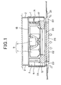
- Fig. 1 is a side cross-sectional view showing an in-ceiling embedded type air conditioner according to an embodiment of the present invention
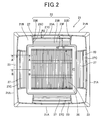
- Fig. 2 is a plan view showing a face panel of the in-ceiling embedded type air conditioner when viewed from a room side to be air-conditioned.
- the in-ceiling embedded type air conditioner has an air conditioner main body 1 formed of a steel plate, and mounted while suspended from the ceiling by suspending bolts 2.
- the air conditioner main body 1 is designed in a substantially rectangular box-shape having an opened lower surface.
- the lower side of the air conditioner main body 1 corresponds to a room to be air-conditioned.
- a heat insulating member 3 of foamed polystyrene is disposed substantially in contact with the inner surface of the side plate 1A of the air conditioner main body 1 to thereby prevent dew condensation at the side plate 1A.
- a motor 5 is fixed to the top plate 1B of the air conditioner main body 1.
- a vane wheel 7 is secured to the shaft of the motor 5, and the motor 5 and the vane wheel 7 constitutes an air blower 9.
- a heat exchanger 11 which is bent (crooked) in a substantially rectangular shape so as to surround the side of the air blower 9.
- a drain pan 13 formed of foamed polystyrene is disposed at the lower side of the heat exchanger 11 so as to cover the lower surface 11A of the heat exchanger 11.
- the drain pan 13 receives drain water occurring in the heat exchanger 11, and various kinds of parts such as a nozzle 17 of the air blower 9, an electrical component box (not shown), etc. are fixed to the drain pan 13 by screws.
- the face panel 21 having the substantially rectangular shape is secured to the lower surface of the air conditioner main body 1 so as to cover a lower-side opening of the air conditioner main body 1.
- Air blow-out ports 24 through which air-conditioned air is supplied into the room to be air-conditioned are formed along four sides of the face panel 21.
- each of the air blow-out ports in the four directions is provided with a flap 27 for changing the air blow-out direction.
- an air suction grill 26 is detachably mounted on the face panel 21 to be located at the center portion surrounded by the air blow-out ports 23 and at the lower side of the air blower 9.
- An air suction port 22 is formed in the air suction grill 26 so as to face the room to be air-conditioned.
- the air suction grill 26 is secured to the face panel 21 through a filter 25.
- the air in the room to be air-conditioned is sucked from the air suction port 22 by the air blower 9, passed through the filter 25 and further the heat exchanger to be heat-exchanged, and then fed out from the air blow-out port 23 into the room to be air-conditioned.
- each of the air blow-out ports in the four directions is compartmented by a pair of long sides 23A and 23B and a pair of short sides 23C and 23d at the position of the surface 21B of the face panel 21, and when viewed from the surface 21B, the air blow-out port is designed to have a trapezoidal shape which gradually expands in width toward the outer edge 21A side of the face panel 21 (i.e. , spatulate form).
- Fig. 3 is a cross-sectional view taken along B-B of Fig. 2
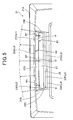
- Fig. 5 is a diagram showing a state that the flap 27 is shifted to a horizontally blow-out position under cooling operation, for example.
- the long side 23A at the outer edge side is designed so that a curved surface 23G is curved toward and terminates at the back side of the air blow-out port 23.
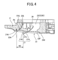
- the curved surface 23G serves as a common curved surface both at the position of Fig. 3 (both the sides of the air blow-out port) and the position of Fig. 4 (the center of the air blow-out port) in the area from the back side of the air blow-out port 23 till A point.
- the curved surface 23G at the center of the air blow-out port ( Fig. 4 ) is more greatly curved than the curved surface 23G at both the sides of the air blow-out port ( Fig.
- the curvature (1/R4, see Fig. 4 ) at the center portion of the air blow-out port in the longitudinal direction of the air blow-out port 23 is larger than the curvature (1/R5, see Fig. 3 ) at both the side portions of the air blow-out port in the longitudinal direction.
- the A point is located at the substantially half height of the whole height H of the air blow-out port in the depth (backward) direction thereof.
- a line L2 at the back end 23E is substantially linear, and a line L3 of the long side 23 is outwardly curved in a convex shape so as to greatly protrude at the center in the longitudinal direction.
- the long side 23B at the inner edge side is gently sloped to the back side of the air blow-out port 23, and terminates at the back end 23F.
- the positions of the long side 23B and the back end 23F are not varied in the longitudinal direction of the air blow-out port 23, and thus as shown in Fig. 3 , both a line L4 at the long side 23B and a line L5 at the back end 23F are linear.
- the substantially rectangular flap 27 for changing the air flowing direction is disposed at each air blow-out port 23.
- the flap 27 has a front face 27A and a back face 27B, and is pivotally mounted on a pair of short sides 23C and 23D through a hinge portion (shaft) 28 provided at the center in the width direction of the back face 27B.
- the shaft 28 is joined to a driving motor (not shown).
- the line L1 of the front edge 27F of the flap 27 is curved to be convex outwardly
- the line L6 of the rear edge 27D of the flap 27 is substantially linear. That is, the front edge 27C of the flap 27 and the outer edge 23A of the air blow-out port 23 which corresponds to the front edge 27C are curved to be convex outwardly.
- the width from the long side 23A at the outer edge side till the back end 23E is set to W1 at the position of Fig. 3 (at both the sides of the air blow-out port) and W2 at the position of Fig. 4 (the center of the air blow-out port) (W2 > W1) in plan view.
- the curvature (1/R1) of the line L1 of the front edge 27C of the flap is substantially equal to the curvature (1/R2) of the line L3 of the outer edge 23A of the air blow-out port, or slightly larger than the curvature (1/R2) of the line L3.
- the pair of short sides 23C and 23D are sloped sideward, and the air blow-out port 23 is designed in such a trapezoidal shape as to gradually expand in width toward the outer edge 21A of the face panel 21. Therefore, at both the sides of the air blow-out port 23 in the longitudinal direction, the air does not suffer flow path resistance of the short sides 23C and 23D and thus it can smoothly flow.
- the shape of the long side 23A of the air blow-out port 23 is set to have a constant curvature (1/R2), (1/R4) or (1/R5). Therefore, as indicated by an arrow of Fig. 5 , air flow along the shape of the long side 23A of the air blow-out port 23 occurs, and the air flow expands in the horizontal direction with Coanda effect. In this construction, the same Coanda effect is obtained for all the four air blow-out ports 23, and the air flow from eachof the air blow-out port expands horizontally. By totalizing these air flows, a circle flow (circle air flow) phenomenon that air flow expands substantially over 360° is obtained.
- the circle air flow can be implemented and gentle air flow expanding in all the directions canbe obtained. Therefore, air flow which has little temperature variation, can suppress undesirable draft feeling and also is comfortable and gentle can be uniformly delivered to the overall room.
- the air blow-out port 23 from the center to both the sides of the air blow-out port 23 in the longitudinal direction is designed so that the air flow velocity from the air blow-out port to the ceiling plane is equal to 1m/sec or less. That is, the air flow velocity at both the sides when the flap 27 is set to the horizontally air blowing position is set to 1m/sec or less.
- the opening area of the air blow-out port 23 is substantially constant in the longitudinal direction. In addition, in this case, the area of the opening is maximum.
- the positional relationship between the flap 27 and the air blow-out port 23 is not uniform.
- the flap 27 is shifted to the horizontal position, the downward blowing position or the intermediate position therebtween, whereby the opening area of the air blow-out port 23 is varied as described above.
Landscapes
- Engineering & Computer Science (AREA)
- Chemical & Material Sciences (AREA)
- Combustion & Propulsion (AREA)
- Mechanical Engineering (AREA)
- General Engineering & Computer Science (AREA)
- Air Filters, Heat-Exchange Apparatuses, And Housings Of Air-Conditioning Units (AREA)
- Air-Flow Control Members (AREA)
- Duct Arrangements (AREA)
- Air-Conditioning Room Units, And Self-Contained Units In General (AREA)
Abstract
Description
- The present invention relates to an in-ceiling embedded type air conditioner having a flap at an air blow-out port thereof.
- There is generally known an in-ceiling embedded type air conditioner which includes an air conditioner main body having a heat exchanger and an air blower mounted therein and a face panel which is disposed on the ceiling plane while assembled with the air conditioner main body and has an air blow-out port for blowing air in four directions. This type of air conditioner has a problem that a flap is shifted to a horizontally air-blowing position under cooling operation, for example, and thus smudge (stain of the ceiling in the neighborhood of the air blow-out port) occurs. This is because the relative humidity of blown-out air is frequently equal to about 90% ore more under cooling operation and thus smudge inside the air conditioner more easily adheres to the ceiling plane.
- With respect to the relationship between the shape of the air blow-out port and the flap, the air flowing speed increases in the neighborhood of the short sides at both the sides in the longitudinal direction of the air blow-out port, and thus the stain of the ceiling plane due to smudging does not occur in the neighborhood of the center of the flap, but frequently occurs at both the sides of the flap. Accordingly, it has been hitherto general that both the sides of the flap are greatly cut out so that blow-out air flows downwardly so as to be far away from the ceiling plane, thereby preventing smudging (see
JP-A-2001-194000 - According to the construction described above, smudging can be prevented, however, there is a problem that cold air drops and thus a user feels draft.
- Therefore, an object of the present invention is to provide an air conditioner that can prevent smudging with making a user feel no draft.
- In order to attain the above object, an in-ceiling embedded type air conditioner including an air conditioner main body (1) having a heat exchanger (11) and an air blower (9) mounted therein and a face panel (21) that is mounted on a ceiling plane while assembled with the air conditioner main body and has air blow-out ports (23) for blowing air in four directions is characterized in that each of the air blow-out ports has a trapezoidal shape which gradually expands in width toward the outer edge of the face panel.
- In the above in-ceiling embedded type air conditioner a flap (27) is provided at each of the air blow-out ports, and a front edge (27C) of the flap is curved to be convex outwardly.
- In the above in-ceiling embedded type air conditioner, an outer long side (23A, 23B) of the air blow-out port (23) has a curved face (23G) that is curved toward a back end (23E) of the air blow-out port, and the curved face is common to the center and both the sides of the air blow-out port in the longitudinal direction thereof from the back-end position till a predetermined position of the air blow-out port and is more greatly curved at the center of the air blow-out port than at both the sides of the air blow-out port from the predetermined position till the surface position of the long side so that the curvature at the center in the longitudinal direction of the air blow-out port is larger than the curvature at both the sides in the longitudinal direction of the air blow-out port.
- In the above in-ceiling embedded type air conditioner, when the flap is shifted to a horizontally air blowing position, the interval between the front edge of the flap and the back end of the air blow-out port increases as the position of the air blow-out port is shifted to both the sides in the longitudinal direction thereof.
- In the above in-ceiling embedded type air conditioner, when the flap is shifted to a downwardly air blowing position, an opening area of the air blowing port is maximum.
- In the above in-ceiling embedded type air conditioner, all the air blow-out ports in the four directions expand current flow in a horizontal direction, thereby implementing circle flow.
- According to the present invention, uniform air flow velocity can be obtained over the air blow-out port without increasing the air flow velocity in the neighborhood of the short sides at both the sides of the air blow-out port in the longitudinal direction. Therefore, stain of a ceiling plane by smudging can be suppressed without making a user feel any draft.
-
-
Fig. 1 is a side cross-sectional view showing an in-ceiling embedded type air conditioner according to an embodiment of the present invention; -
Fig. 2 is a plan view showing a face panel secured to the in-ceiling embedded type air conditioner; -
Fig. 3 is a cross-sectional view taken along A-A ofFig. 2 ; -
Fig. 4 is a cross-sectional view taken along B-B ofFig. 2 ; -
Fig. 5 is a diagram showing a state that a flap is shifted to a horizontally air-blowing position; and -
Fig. 6 is a diagram showing a state that the flap is shifted to a downward air-blowing position. - A preferred embodiment according to the present invention will be described hereunder with reference to the accompanying drawings.
-
Fig. 1 is a side cross-sectional view showing an in-ceiling embedded type air conditioner according to an embodiment of the present invention, andFig. 2 is a plan view showing a face panel of the in-ceiling embedded type air conditioner when viewed from a room side to be air-conditioned. - As shown in
Fig. 1 , the in-ceiling embedded type air conditioner has an air conditioner main body 1 formed of a steel plate, and mounted while suspended from the ceiling by suspendingbolts 2. - The air conditioner main body 1 is designed in a substantially rectangular box-shape having an opened lower surface. In
Fig. 1 , the lower side of the air conditioner main body 1 corresponds to a room to be air-conditioned. Aheat insulating member 3 of foamed polystyrene is disposed substantially in contact with the inner surface of theside plate 1A of the air conditioner main body 1 to thereby prevent dew condensation at theside plate 1A. - A
motor 5 is fixed to thetop plate 1B of the air conditioner main body 1. A vane wheel 7 is secured to the shaft of themotor 5, and themotor 5 and the vane wheel 7 constitutes anair blower 9. Aheat exchanger 11 which is bent (crooked) in a substantially rectangular shape so as to surround the side of theair blower 9. Adrain pan 13 formed of foamed polystyrene is disposed at the lower side of theheat exchanger 11 so as to cover thelower surface 11A of theheat exchanger 11. Thedrain pan 13 receives drain water occurring in theheat exchanger 11, and various kinds of parts such as anozzle 17 of theair blower 9, an electrical component box (not shown), etc. are fixed to thedrain pan 13 by screws. - As shown in
Figs. 1 and2 , theface panel 21 having the substantially rectangular shape is secured to the lower surface of the air conditioner main body 1 so as to cover a lower-side opening of the air conditioner main body 1. Air blow-out ports 24 through which air-conditioned air is supplied into the room to be air-conditioned are formed along four sides of theface panel 21. As shown inFig. 2 , each of the air blow-out ports in the four directions is provided with aflap 27 for changing the air blow-out direction. Furthermore, anair suction grill 26 is detachably mounted on theface panel 21 to be located at the center portion surrounded by the air blow-outports 23 and at the lower side of theair blower 9. Anair suction port 22 is formed in theair suction grill 26 so as to face the room to be air-conditioned. Theair suction grill 26 is secured to theface panel 21 through afilter 25. - Accordingly, the air in the room to be air-conditioned is sucked from the
air suction port 22 by theair blower 9, passed through thefilter 25 and further the heat exchanger to be heat-exchanged, and then fed out from the air blow-outport 23 into the room to be air-conditioned. - In this embodiment, each of the air blow-out ports in the four directions is compartmented by a pair of
long sides short sides 23C and 23d at the position of thesurface 21B of theface panel 21, and when viewed from thesurface 21B, the air blow-out port is designed to have a trapezoidal shape which gradually expands in width toward theouter edge 21A side of the face panel 21 (i.e. , spatulate form). -
Fig. 3 is a cross-sectional view taken along B-B ofFig. 2 , andFig. 5 is a diagram showing a state that theflap 27 is shifted to a horizontally blow-out position under cooling operation, for example. - As shown in
Figs. 3 and4 , thelong side 23A at the outer edge side is designed so that acurved surface 23G is curved toward and terminates at the back side of the air blow-outport 23. Thecurved surface 23G serves as a common curved surface both at the position ofFig. 3 (both the sides of the air blow-out port) and the position ofFig. 4 (the center of the air blow-out port) in the area from the back side of the air blow-outport 23 till A point. In the area from the position of the point till thelong side 23A, thecurved surface 23G at the center of the air blow-out port (Fig. 4 ) is more greatly curved than thecurved surface 23G at both the sides of the air blow-out port (Fig. 3 ) . That is, with respect to the curvature of thecurved surface 23G from the A point till thelong side 23A, the curvature (1/R4, seeFig. 4 ) at the center portion of the air blow-out port in the longitudinal direction of the air blow-outport 23 is larger than the curvature (1/R5, seeFig. 3 ) at both the side portions of the air blow-out port in the longitudinal direction. Here, as shown inFig. 3 , the A point is located at the substantially half height of the whole height H of the air blow-out port in the depth (backward) direction thereof. - In this embodiment, as shown in
Fig. 5 , a line L2 at theback end 23E is substantially linear, and a line L3 of thelong side 23 is outwardly curved in a convex shape so as to greatly protrude at the center in the longitudinal direction. As shown inFigs. 3 and4 , thelong side 23B at the inner edge side is gently sloped to the back side of the air blow-outport 23, and terminates at theback end 23F. The positions of thelong side 23B and theback end 23F are not varied in the longitudinal direction of the air blow-outport 23, and thus as shown inFig. 3 , both a line L4 at thelong side 23B and a line L5 at theback end 23F are linear. - The substantially
rectangular flap 27 for changing the air flowing direction is disposed at each air blow-outport 23. Theflap 27 has afront face 27A and aback face 27B, and is pivotally mounted on a pair ofshort sides back face 27B. Theshaft 28 is joined to a driving motor (not shown). As shown inFig. 5 , the line L1 of the front edge 27F of theflap 27 is curved to be convex outwardly, and the line L6 of therear edge 27D of theflap 27 is substantially linear. That is, thefront edge 27C of theflap 27 and theouter edge 23A of the air blow-outport 23 which corresponds to thefront edge 27C are curved to be convex outwardly. - As shown in
Figs. 3 to 5 , the width from thelong side 23A at the outer edge side till theback end 23E is set to W1 at the position ofFig. 3 (at both the sides of the air blow-out port) and W2 at the position ofFig. 4 (the center of the air blow-out port) (W2 > W1) in plan view. As shown inFig. 5 , the interval between thefront edge 27C of theflap 27 and theback end 23E of the air blow-outport 23 is set to t1 at both the sides of the air blow-out port and t2 (=0) at the center of the air blow-out port. - Furthermore, the curvature (1/R1) of the line L1 of the
front edge 27C of the flap is substantially equal to the curvature (1/R2) of the line L3 of theouter edge 23A of the air blow-out port, or slightly larger than the curvature (1/R2) of the line L3. - In this embodiment, as shown in
Fig. 5 , when theflap 27 is shifted to the horizontally air blow-out position, the interval between thefront edge 27C of theflap 27 and theback end 23E of the air blow-outport 23 increases as the position is shifted to both the sides of the air blow-outport 23 in the longitudinal direction. Accordingly, when the cross-section of the air blow-outport 23 is viewed, the air blow-out opening having substantially the same area between the position ofFig. 3 and the position ofFig. 4 can be secured, and thus substantially the same air flow amount can be secured at the center and both the sides of the air blow-outport 23. - Furthermore, as shown in
Fig. 5 , the pair ofshort sides port 23 is designed in such a trapezoidal shape as to gradually expand in width toward theouter edge 21A of theface panel 21. Therefore, at both the sides of the air blow-outport 23 in the longitudinal direction, the air does not suffer flow path resistance of theshort sides - Accordingly, the phenomenon that the air flow velocity increases more greatly at both the pair of
short sides port 23. Therefore, occurrence of so-called smudging which is caused by the increase of the air flow velocity at theshort sides - The shape of the
long side 23A of the air blow-outport 23 is set to have a constant curvature (1/R2), (1/R4) or (1/R5). Therefore, as indicated by an arrow ofFig. 5 , air flow along the shape of thelong side 23A of the air blow-outport 23 occurs, and the air flow expands in the horizontal direction with Coanda effect. In this construction, the same Coanda effect is obtained for all the four air blow-outports 23, and the air flow from eachof the air blow-out port expands horizontally. By totalizing these air flows, a circle flow (circle air flow) phenomenon that air flow expands substantially over 360° is obtained. - In this construction, the circle air flow can be implemented and gentle air flow expanding in all the directions canbe obtained. Therefore, air flow which has little temperature variation, can suppress undesirable draft feeling and also is comfortable and gentle can be uniformly delivered to the overall room.
- Furthermore, it was found in a past experimental result that when the air flow velocity from the air blow-out
port 23 was equal to 1m/sec or more, the ceiling plane is more easily splotched. - In this construction, the air blow-out
port 23 from the center to both the sides of the air blow-outport 23 in the longitudinal direction is designed so that the air flow velocity from the air blow-out port to the ceiling plane is equal to 1m/sec or less. That is, the air flow velocity at both the sides when theflap 27 is set to the horizontally air blowing position is set to 1m/sec or less. - According to this embodiment, as shown in
Fig. 6 , when theflap 27 is shifted to the downward air blow-out position under heating operation or the like, the opening area of the air blow-outport 23 is substantially constant in the longitudinal direction. In addition, in this case, the area of the opening is maximum. - As described above, in the above construction, the positional relationship between the
flap 27 and the air blow-outport 23 is not uniform. Theflap 27 is shifted to the horizontal position, the downward blowing position or the intermediate position therebtween, whereby the opening area of the air blow-outport 23 is varied as described above. - The present invention is not limited to the above embodiment, and various modifications may be made without departing from the subject matter of the present invention.
Claims (6)
- An in-ceiling embedded type air conditioner including an air conditioner main body (1) having a heat exchanger (11) and an air blower (9) mounted therein and a face panel (21) that is mounted on a ceiling plane while assembled with the air conditioner main body and has air blow-out ports (23) for blowing air in four directions, characterized in that each of the air blow-out ports has a trapezoidal shape which gradually expands in width toward the outer edge of the face panel.
- The in-ceiling embedded type air conditioner according to claim 1, wherein a flap (27) is provided at each of the air blow-out ports, and a front edge (27C) of the flap is curved to be convex outwardly.
- The in-ceiling embedded type air conditioner according to claim 1 or 2, wherein an outer long side (23A, 23B) of the air blow-out port (23) has a curved face (23G) that is curved toward a back end (23E) of the air blow-out port, and the curved face is common to the center and both the sides of the air blow-out port in the longitudinal direction thereof from the back-end position till a predetermined position of the air blow-out port and is more greatly curved at the center of the air blow-out port than at both the sides of the air blow-out port from the predetermined position till the surface position of the long side so that the curvature at the center in the longitudinal direction of the air blow-out port is larger than the curvature at both the sides in the longitudinal direction of the air blow-out port.
- The in-ceiling embedded type air conditioner according to claim 2 or 3, wherein when the flap is shifted to a horizontally air blowing position, the interval between the front edge of the flap and the back end of the air blow-out port increases as the position of the air blow-out port is shifted to both the sides in the longitudinal direction thereof.
- The in-ceiling embedded type air conditioner according to any one of claims 2 to 4, wherein when the flap is shifted to a downwardly air blowing position, an opening area of the air blowing port is maximum.
- The in-ceiling embedded type air conditioner according to any one of claims 1 to 5, wherein all the air blow-out ports in the four directions expand current flow in a horizontal direction, thereby implementing circle flow.
Applications Claiming Priority (1)
| Application Number | Priority Date | Filing Date | Title |
|---|---|---|---|
| JP2009174323A JP5456402B2 (en) | 2009-07-27 | 2009-07-27 | Embedded ceiling air conditioner |
Publications (3)
| Publication Number | Publication Date |
|---|---|
| EP2295878A2 true EP2295878A2 (en) | 2011-03-16 |
| EP2295878A3 EP2295878A3 (en) | 2014-12-10 |
| EP2295878B1 EP2295878B1 (en) | 2018-04-11 |
Family
ID=43034327
Family Applications (1)
| Application Number | Title | Priority Date | Filing Date |
|---|---|---|---|
| EP10007746.0A Not-in-force EP2295878B1 (en) | 2009-07-27 | 2010-07-26 | In-ceiling embedded type air conditioner |
Country Status (3)
| Country | Link |
|---|---|
| EP (1) | EP2295878B1 (en) |
| JP (1) | JP5456402B2 (en) |
| CN (1) | CN101968258A (en) |
Cited By (3)
| Publication number | Priority date | Publication date | Assignee | Title |
|---|---|---|---|---|
| GB2511148A (en) * | 2013-06-18 | 2014-08-27 | Vkr Holding As | Grill arrangement |
| EP2918936A4 (en) * | 2012-10-30 | 2016-07-27 | Mitsubishi Electric Corp | AIR CONDITIONER |
| US11156372B2 (en) | 2017-01-30 | 2021-10-26 | Mitsubishi Electric Corporation | Indoor unit for ceiling-concealed air-conditioning apparatus, and ceiling-concealed air-conditioning apparatus including the same |
Families Citing this family (6)
| Publication number | Priority date | Publication date | Assignee | Title |
|---|---|---|---|---|
| CN104697138B (en) * | 2013-12-04 | 2018-04-03 | 海尔集团公司 | Embedded type air conditioner panel and embedded type air conditioner |
| JP6072671B2 (en) * | 2013-12-20 | 2017-02-01 | 三菱電機株式会社 | Indoor unit and air conditioner |
| AU2014379851B2 (en) * | 2014-01-24 | 2018-01-04 | Toshiba Carrier Corporation | Air conditioner |
| CN105003961B (en) * | 2014-09-24 | 2017-12-26 | 黄欣欣 | A kind of embedded air-conditioner indoor set |
| CN104456724A (en) * | 2014-10-29 | 2015-03-25 | 珠海格力电器股份有限公司 | Air conditioner |
| JP6776531B2 (en) * | 2015-12-22 | 2020-10-28 | ダイキン工業株式会社 | Indoor unit of air conditioner |
Citations (1)
| Publication number | Priority date | Publication date | Assignee | Title |
|---|---|---|---|---|
| JP2001194000A (en) | 1999-11-05 | 2001-07-17 | Daikin Ind Ltd | Ceiling-mounted air conditioner |
Family Cites Families (13)
| Publication number | Priority date | Publication date | Assignee | Title |
|---|---|---|---|---|
| JPS62166250A (en) * | 1986-01-20 | 1987-07-22 | Matsushita Electric Ind Co Ltd | Air conditioner wind deflection device |
| JP3438323B2 (en) * | 1994-06-01 | 2003-08-18 | ダイキン工業株式会社 | Ceiling embedded air conditioner and horizontal blade structure of the device |
| JP2001004198A (en) * | 1999-06-25 | 2001-01-12 | Matsushita Refrig Co Ltd | Air conditioner |
| JP3957927B2 (en) * | 1999-08-30 | 2007-08-15 | 三菱重工業株式会社 | Embedded ceiling air conditioner |
| JP3624808B2 (en) * | 2000-08-11 | 2005-03-02 | ダイキン工業株式会社 | Air conditioner decorative panel, air outlet unit, and air conditioner |
| JP3624814B2 (en) * | 2000-09-06 | 2005-03-02 | ダイキン工業株式会社 | Air conditioner decorative panel, air outlet unit, and air conditioner |
| CN1231726C (en) * | 2001-10-10 | 2005-12-14 | 乐金电子(天津)电器有限公司 | Ceiling board type air conditioner |
| JP2007024345A (en) * | 2005-07-12 | 2007-02-01 | Mitsubishi Electric Corp | Air conditioner |
| EP1752717B1 (en) * | 2005-08-09 | 2008-07-09 | Dometic WTA S.R.L. | Air diffuser for an air conditioner |
| KR20070033531A (en) * | 2005-09-21 | 2007-03-27 | 삼성전자주식회사 | Ceiling air conditioners |
| KR100972273B1 (en) * | 2007-07-25 | 2010-07-23 | 산요덴키가부시키가이샤 | Indoor unit of ceiling flush air conditioner |
| KR101160401B1 (en) * | 2007-10-25 | 2012-06-26 | 도시바 캐리어 가부시키가이샤 | Ceiling-embedded air conditioner |
| JP2009103420A (en) * | 2007-10-26 | 2009-05-14 | Fujitsu General Ltd | Air conditioner |
-
2009
- 2009-07-27 JP JP2009174323A patent/JP5456402B2/en not_active Expired - Fee Related
-
2010
- 2010-07-23 CN CN2010102366495A patent/CN101968258A/en active Pending
- 2010-07-26 EP EP10007746.0A patent/EP2295878B1/en not_active Not-in-force
Patent Citations (1)
| Publication number | Priority date | Publication date | Assignee | Title |
|---|---|---|---|---|
| JP2001194000A (en) | 1999-11-05 | 2001-07-17 | Daikin Ind Ltd | Ceiling-mounted air conditioner |
Cited By (6)
| Publication number | Priority date | Publication date | Assignee | Title |
|---|---|---|---|---|
| EP2918936A4 (en) * | 2012-10-30 | 2016-07-27 | Mitsubishi Electric Corp | AIR CONDITIONER |
| US9995504B2 (en) | 2012-10-30 | 2018-06-12 | Mitsubishi Electric Corporation | Air conditioner having air outlet louver with varying curvature |
| GB2511148A (en) * | 2013-06-18 | 2014-08-27 | Vkr Holding As | Grill arrangement |
| EP2816294A3 (en) * | 2013-06-18 | 2015-07-22 | VKR Holding A/S | Grill arrangement |
| GB2511148B (en) * | 2013-06-18 | 2017-11-15 | Vkr Holding As | Grill arrangement |
| US11156372B2 (en) | 2017-01-30 | 2021-10-26 | Mitsubishi Electric Corporation | Indoor unit for ceiling-concealed air-conditioning apparatus, and ceiling-concealed air-conditioning apparatus including the same |
Also Published As
| Publication number | Publication date |
|---|---|
| CN101968258A (en) | 2011-02-09 |
| EP2295878A3 (en) | 2014-12-10 |
| EP2295878B1 (en) | 2018-04-11 |
| JP5456402B2 (en) | 2014-03-26 |
| JP2011027336A (en) | 2011-02-10 |
Similar Documents
| Publication | Publication Date | Title |
|---|---|---|
| EP2295878B1 (en) | In-ceiling embedded type air conditioner | |
| US9157673B2 (en) | Wall-mounted air-conditioning apparatus | |
| CN104024759B (en) | Air conditioner | |
| AU2014379851B2 (en) | Air conditioner | |
| CN110068049B (en) | Cabinet air conditioner and shutdown control method thereof | |
| JP4947227B1 (en) | Air conditioner | |
| JP2012078031A (en) | Air conditioner | |
| CN101802509A (en) | Ceiling-embedded air conditioner | |
| CN102227595B (en) | Air conditioning device | |
| EP3348929B1 (en) | Air-conditioning indoor unit | |
| JP2014126282A (en) | Ceiling mounted indoor unit | |
| CN107477684A (en) | Air-cooled ducted air conditioner | |
| JP4906828B2 (en) | Air conditioner | |
| JP2001304674A (en) | Air conditioner indoor unit | |
| CN107208926B (en) | air conditioner indoor unit | |
| JP2014122750A (en) | Air conditioner | |
| JP2003227648A (en) | Makeup panel for ceiling cassette type air conditioner | |
| JP2003343872A (en) | Floor type air conditioner | |
| CN210154043U (en) | Wind-guiding part, wind-guiding device and air conditioner | |
| JP5786849B2 (en) | Ceiling-mounted indoor unit | |
| JP2019020079A (en) | Flap and wall-mounted room air conditioner indoor unit with the same | |
| JP2004218877A (en) | Blower | |
| JP5870251B2 (en) | Air conditioner | |
| JP2021014952A (en) | Air conditioner | |
| JP2014234963A (en) | Air conditioner |
Legal Events
| Date | Code | Title | Description |
|---|---|---|---|
| PUAI | Public reference made under article 153(3) epc to a published international application that has entered the european phase |
Free format text: ORIGINAL CODE: 0009012 |
|
| AK | Designated contracting states |
Kind code of ref document: A2 Designated state(s): AL AT BE BG CH CY CZ DE DK EE ES FI FR GB GR HR HU IE IS IT LI LT LU LV MC MK MT NL NO PL PT RO SE SI SK SM TR |
|
| AX | Request for extension of the european patent |
Extension state: BA ME RS |
|
| PUAL | Search report despatched |
Free format text: ORIGINAL CODE: 0009013 |
|
| AK | Designated contracting states |
Kind code of ref document: A3 Designated state(s): AL AT BE BG CH CY CZ DE DK EE ES FI FR GB GR HR HU IE IS IT LI LT LU LV MC MK MT NL NO PL PT RO SE SI SK SM TR |
|
| AX | Request for extension of the european patent |
Extension state: BA ME RS |
|
| RIC1 | Information provided on ipc code assigned before grant |
Ipc: F24F 1/00 20110101AFI20141104BHEP Ipc: F24F 13/14 20060101ALN20141104BHEP |
|
| 17P | Request for examination filed |
Effective date: 20150529 |
|
| RBV | Designated contracting states (corrected) |
Designated state(s): AL AT BE BG CH CY CZ DE DK EE ES FI FR GB GR HR HU IE IS IT LI LT LU LV MC MK MT NL NO PL PT RO SE SI SK SM TR |
|
| 17Q | First examination report despatched |
Effective date: 20160829 |
|
| STAA | Information on the status of an ep patent application or granted ep patent |
Free format text: STATUS: EXAMINATION IS IN PROGRESS |
|
| GRAP | Despatch of communication of intention to grant a patent |
Free format text: ORIGINAL CODE: EPIDOSNIGR1 |
|
| STAA | Information on the status of an ep patent application or granted ep patent |
Free format text: STATUS: GRANT OF PATENT IS INTENDED |
|
| RIC1 | Information provided on ipc code assigned before grant |
Ipc: F24F 13/14 20060101ALN20171009BHEP Ipc: F24F 1/00 20110101AFI20171009BHEP |
|
| INTG | Intention to grant announced |
Effective date: 20171030 |
|
| GRAS | Grant fee paid |
Free format text: ORIGINAL CODE: EPIDOSNIGR3 |
|
| GRAA | (expected) grant |
Free format text: ORIGINAL CODE: 0009210 |
|
| STAA | Information on the status of an ep patent application or granted ep patent |
Free format text: STATUS: THE PATENT HAS BEEN GRANTED |
|
| AK | Designated contracting states |
Kind code of ref document: B1 Designated state(s): AL AT BE BG CH CY CZ DE DK EE ES FI FR GB GR HR HU IE IS IT LI LT LU LV MC MK MT NL NO PL PT RO SE SI SK SM TR |
|
| REG | Reference to a national code |
Ref country code: GB Ref legal event code: FG4D |
|
| REG | Reference to a national code |
Ref country code: CH Ref legal event code: EP |
|
| REG | Reference to a national code |
Ref country code: AT Ref legal event code: REF Ref document number: 988456 Country of ref document: AT Kind code of ref document: T Effective date: 20180415 |
|
| REG | Reference to a national code |
Ref country code: IE Ref legal event code: FG4D |
|
| REG | Reference to a national code |
Ref country code: DE Ref legal event code: R096 Ref document number: 602010049784 Country of ref document: DE |
|
| REG | Reference to a national code |
Ref country code: FR Ref legal event code: PLFP Year of fee payment: 9 |
|
| REG | Reference to a national code |
Ref country code: NL Ref legal event code: MP Effective date: 20180411 |
|
| REG | Reference to a national code |
Ref country code: LT Ref legal event code: MG4D |
|
| PG25 | Lapsed in a contracting state [announced via postgrant information from national office to epo] |
Ref country code: NL Free format text: LAPSE BECAUSE OF FAILURE TO SUBMIT A TRANSLATION OF THE DESCRIPTION OR TO PAY THE FEE WITHIN THE PRESCRIBED TIME-LIMIT Effective date: 20180411 |
|
| PG25 | Lapsed in a contracting state [announced via postgrant information from national office to epo] |
Ref country code: PL Free format text: LAPSE BECAUSE OF FAILURE TO SUBMIT A TRANSLATION OF THE DESCRIPTION OR TO PAY THE FEE WITHIN THE PRESCRIBED TIME-LIMIT Effective date: 20180411 Ref country code: LT Free format text: LAPSE BECAUSE OF FAILURE TO SUBMIT A TRANSLATION OF THE DESCRIPTION OR TO PAY THE FEE WITHIN THE PRESCRIBED TIME-LIMIT Effective date: 20180411 Ref country code: BG Free format text: LAPSE BECAUSE OF FAILURE TO SUBMIT A TRANSLATION OF THE DESCRIPTION OR TO PAY THE FEE WITHIN THE PRESCRIBED TIME-LIMIT Effective date: 20180711 Ref country code: SE Free format text: LAPSE BECAUSE OF FAILURE TO SUBMIT A TRANSLATION OF THE DESCRIPTION OR TO PAY THE FEE WITHIN THE PRESCRIBED TIME-LIMIT Effective date: 20180411 Ref country code: NO Free format text: LAPSE BECAUSE OF FAILURE TO SUBMIT A TRANSLATION OF THE DESCRIPTION OR TO PAY THE FEE WITHIN THE PRESCRIBED TIME-LIMIT Effective date: 20180711 Ref country code: AL Free format text: LAPSE BECAUSE OF FAILURE TO SUBMIT A TRANSLATION OF THE DESCRIPTION OR TO PAY THE FEE WITHIN THE PRESCRIBED TIME-LIMIT Effective date: 20180411 Ref country code: FI Free format text: LAPSE BECAUSE OF FAILURE TO SUBMIT A TRANSLATION OF THE DESCRIPTION OR TO PAY THE FEE WITHIN THE PRESCRIBED TIME-LIMIT Effective date: 20180411 Ref country code: ES Free format text: LAPSE BECAUSE OF FAILURE TO SUBMIT A TRANSLATION OF THE DESCRIPTION OR TO PAY THE FEE WITHIN THE PRESCRIBED TIME-LIMIT Effective date: 20180411 |
|
| PG25 | Lapsed in a contracting state [announced via postgrant information from national office to epo] |
Ref country code: HR Free format text: LAPSE BECAUSE OF FAILURE TO SUBMIT A TRANSLATION OF THE DESCRIPTION OR TO PAY THE FEE WITHIN THE PRESCRIBED TIME-LIMIT Effective date: 20180411 Ref country code: GR Free format text: LAPSE BECAUSE OF FAILURE TO SUBMIT A TRANSLATION OF THE DESCRIPTION OR TO PAY THE FEE WITHIN THE PRESCRIBED TIME-LIMIT Effective date: 20180712 Ref country code: LV Free format text: LAPSE BECAUSE OF FAILURE TO SUBMIT A TRANSLATION OF THE DESCRIPTION OR TO PAY THE FEE WITHIN THE PRESCRIBED TIME-LIMIT Effective date: 20180411 |
|
| REG | Reference to a national code |
Ref country code: AT Ref legal event code: MK05 Ref document number: 988456 Country of ref document: AT Kind code of ref document: T Effective date: 20180411 |
|
| PG25 | Lapsed in a contracting state [announced via postgrant information from national office to epo] |
Ref country code: PT Free format text: LAPSE BECAUSE OF FAILURE TO SUBMIT A TRANSLATION OF THE DESCRIPTION OR TO PAY THE FEE WITHIN THE PRESCRIBED TIME-LIMIT Effective date: 20180813 |
|
| REG | Reference to a national code |
Ref country code: DE Ref legal event code: R097 Ref document number: 602010049784 Country of ref document: DE |
|
| PG25 | Lapsed in a contracting state [announced via postgrant information from national office to epo] |
Ref country code: SK Free format text: LAPSE BECAUSE OF FAILURE TO SUBMIT A TRANSLATION OF THE DESCRIPTION OR TO PAY THE FEE WITHIN THE PRESCRIBED TIME-LIMIT Effective date: 20180411 Ref country code: RO Free format text: LAPSE BECAUSE OF FAILURE TO SUBMIT A TRANSLATION OF THE DESCRIPTION OR TO PAY THE FEE WITHIN THE PRESCRIBED TIME-LIMIT Effective date: 20180411 Ref country code: CZ Free format text: LAPSE BECAUSE OF FAILURE TO SUBMIT A TRANSLATION OF THE DESCRIPTION OR TO PAY THE FEE WITHIN THE PRESCRIBED TIME-LIMIT Effective date: 20180411 Ref country code: DK Free format text: LAPSE BECAUSE OF FAILURE TO SUBMIT A TRANSLATION OF THE DESCRIPTION OR TO PAY THE FEE WITHIN THE PRESCRIBED TIME-LIMIT Effective date: 20180411 Ref country code: EE Free format text: LAPSE BECAUSE OF FAILURE TO SUBMIT A TRANSLATION OF THE DESCRIPTION OR TO PAY THE FEE WITHIN THE PRESCRIBED TIME-LIMIT Effective date: 20180411 Ref country code: AT Free format text: LAPSE BECAUSE OF FAILURE TO SUBMIT A TRANSLATION OF THE DESCRIPTION OR TO PAY THE FEE WITHIN THE PRESCRIBED TIME-LIMIT Effective date: 20180411 |
|
| PLBE | No opposition filed within time limit |
Free format text: ORIGINAL CODE: 0009261 |
|
| STAA | Information on the status of an ep patent application or granted ep patent |
Free format text: STATUS: NO OPPOSITION FILED WITHIN TIME LIMIT |
|
| PG25 | Lapsed in a contracting state [announced via postgrant information from national office to epo] |
Ref country code: SM Free format text: LAPSE BECAUSE OF FAILURE TO SUBMIT A TRANSLATION OF THE DESCRIPTION OR TO PAY THE FEE WITHIN THE PRESCRIBED TIME-LIMIT Effective date: 20180411 Ref country code: IT Free format text: LAPSE BECAUSE OF FAILURE TO SUBMIT A TRANSLATION OF THE DESCRIPTION OR TO PAY THE FEE WITHIN THE PRESCRIBED TIME-LIMIT Effective date: 20180411 |
|
| REG | Reference to a national code |
Ref country code: CH Ref legal event code: PL |
|
| 26N | No opposition filed |
Effective date: 20190114 |
|
| PG25 | Lapsed in a contracting state [announced via postgrant information from national office to epo] |
Ref country code: MC Free format text: LAPSE BECAUSE OF FAILURE TO SUBMIT A TRANSLATION OF THE DESCRIPTION OR TO PAY THE FEE WITHIN THE PRESCRIBED TIME-LIMIT Effective date: 20180411 Ref country code: LU Free format text: LAPSE BECAUSE OF NON-PAYMENT OF DUE FEES Effective date: 20180726 |
|
| REG | Reference to a national code |
Ref country code: BE Ref legal event code: MM Effective date: 20180731 |
|
| REG | Reference to a national code |
Ref country code: IE Ref legal event code: MM4A |
|
| PG25 | Lapsed in a contracting state [announced via postgrant information from national office to epo] |
Ref country code: IE Free format text: LAPSE BECAUSE OF NON-PAYMENT OF DUE FEES Effective date: 20180726 Ref country code: LI Free format text: LAPSE BECAUSE OF NON-PAYMENT OF DUE FEES Effective date: 20180731 Ref country code: CH Free format text: LAPSE BECAUSE OF NON-PAYMENT OF DUE FEES Effective date: 20180731 |
|
| PG25 | Lapsed in a contracting state [announced via postgrant information from national office to epo] |
Ref country code: SI Free format text: LAPSE BECAUSE OF FAILURE TO SUBMIT A TRANSLATION OF THE DESCRIPTION OR TO PAY THE FEE WITHIN THE PRESCRIBED TIME-LIMIT Effective date: 20180411 Ref country code: BE Free format text: LAPSE BECAUSE OF NON-PAYMENT OF DUE FEES Effective date: 20180731 |
|
| PG25 | Lapsed in a contracting state [announced via postgrant information from national office to epo] |
Ref country code: MT Free format text: LAPSE BECAUSE OF NON-PAYMENT OF DUE FEES Effective date: 20180726 |
|
| PG25 | Lapsed in a contracting state [announced via postgrant information from national office to epo] |
Ref country code: TR Free format text: LAPSE BECAUSE OF FAILURE TO SUBMIT A TRANSLATION OF THE DESCRIPTION OR TO PAY THE FEE WITHIN THE PRESCRIBED TIME-LIMIT Effective date: 20180411 |
|
| PG25 | Lapsed in a contracting state [announced via postgrant information from national office to epo] |
Ref country code: HU Free format text: LAPSE BECAUSE OF FAILURE TO SUBMIT A TRANSLATION OF THE DESCRIPTION OR TO PAY THE FEE WITHIN THE PRESCRIBED TIME-LIMIT; INVALID AB INITIO Effective date: 20100726 |
|
| PG25 | Lapsed in a contracting state [announced via postgrant information from national office to epo] |
Ref country code: MK Free format text: LAPSE BECAUSE OF NON-PAYMENT OF DUE FEES Effective date: 20180411 Ref country code: CY Free format text: LAPSE BECAUSE OF FAILURE TO SUBMIT A TRANSLATION OF THE DESCRIPTION OR TO PAY THE FEE WITHIN THE PRESCRIBED TIME-LIMIT Effective date: 20180411 |
|
| PG25 | Lapsed in a contracting state [announced via postgrant information from national office to epo] |
Ref country code: IS Free format text: LAPSE BECAUSE OF FAILURE TO SUBMIT A TRANSLATION OF THE DESCRIPTION OR TO PAY THE FEE WITHIN THE PRESCRIBED TIME-LIMIT Effective date: 20180811 |
|
| PGFP | Annual fee paid to national office [announced via postgrant information from national office to epo] |
Ref country code: FR Payment date: 20220421 Year of fee payment: 13 |
|
| PGFP | Annual fee paid to national office [announced via postgrant information from national office to epo] |
Ref country code: GB Payment date: 20220721 Year of fee payment: 13 Ref country code: DE Payment date: 20220609 Year of fee payment: 13 |
|
| REG | Reference to a national code |
Ref country code: DE Ref legal event code: R119 Ref document number: 602010049784 Country of ref document: DE |
|
| GBPC | Gb: european patent ceased through non-payment of renewal fee |
Effective date: 20230726 |
|
| PG25 | Lapsed in a contracting state [announced via postgrant information from national office to epo] |
Ref country code: DE Free format text: LAPSE BECAUSE OF NON-PAYMENT OF DUE FEES Effective date: 20240201 Ref country code: GB Free format text: LAPSE BECAUSE OF NON-PAYMENT OF DUE FEES Effective date: 20230726 |
|
| PG25 | Lapsed in a contracting state [announced via postgrant information from national office to epo] |
Ref country code: FR Free format text: LAPSE BECAUSE OF NON-PAYMENT OF DUE FEES Effective date: 20230731 |