EP2295265B1 - Folding decoration device - Google Patents
Folding decoration device Download PDFInfo
- Publication number
- EP2295265B1 EP2295265B1 EP20100006834 EP10006834A EP2295265B1 EP 2295265 B1 EP2295265 B1 EP 2295265B1 EP 20100006834 EP20100006834 EP 20100006834 EP 10006834 A EP10006834 A EP 10006834A EP 2295265 B1 EP2295265 B1 EP 2295265B1
- Authority
- EP
- European Patent Office
- Prior art keywords
- decoration
- decoration portion
- planar base
- decoration device
- circuit module
- Prior art date
- Legal status (The legal status is an assumption and is not a legal conclusion. Google has not performed a legal analysis and makes no representation as to the accuracy of the status listed.)
- Active
Links
Images



Classifications
-
- B—PERFORMING OPERATIONS; TRANSPORTING
- B44—DECORATIVE ARTS
- B44C—PRODUCING DECORATIVE EFFECTS; MOSAICS; TARSIA WORK; PAPERHANGING
- B44C5/00—Processes for producing special ornamental bodies
Definitions
- This invention relates to a decoration device and, more particularly, to a decoration device incorporating an electronic element.
- a decoration device (such as wallpaper and wall sticker) generally for improving environmental aesthetic mostly has changes in color and material.
- wallpaper may cooperate with brightness of lamps to achieve an effect, or wallpaper with a three-dimensional design instead of a plane design may be used.
- they are all stereotypes aiming at the visual effect.
- the interactive window curtain As a general plane device is considered, at present, there are an interactive window curtain combined with man-machine interaction such as scene wallpaper and a device disposed at a wall surface and capable of interacting with users.
- the interactive window curtain is considered, a frame similar to outside views is embedded in a wall surface or a window frame surface, and the frame has a light control and sound switching function. Thereby, although people stay in the room, they can feel as staying in the outside views with different climate and environment.
- the device is essentially a computer which is embedded into the wall surface and is capable of interacting with the users. The device cooperates with a frame or a support and a material to allow a general exposed computer screen to pretend to one portion of the wall or furniture.
- the objective of the above design is to hide the originally exposed computer to provide a protecting function instead of providing actual functional operation.
- GB 2 295 044 discloses a prior art decoration device.
- a decoration device including a foldable element, an electronic element, and a sensing element.
- the foldable element includes a planar base portion and a decoration portion.
- the decoration portion is connected with the planar base portion.
- the foldable element changes between a folded state and an unfolded state by an external force.
- the decoration portion is folded when the foldable element is in the folded state.
- the electronic element is connected with the planar base portion.
- the sensing element senses a status of the foldable element to control the electronic element.
- the decoration portion further includes a driving circuit module capable of generating the external force to allow the foldable element to change to the folded state or the unfolded state.
- the planar base portion may be a first sheet, and the first sheet may be selected from the group consisting of paper, a plastic material, an adhering material, and a fiber material.
- the planar base portion of the foldable element may be a wall sticker.
- the decoration device may further include a supporting assembly connected with the planar base portion and the decoration portion to support the foldable element to be fixed to one intermediate state between the folded state and the unfolded state.
- the decoration portion may be folded from at least one second sheet and be folded or unfolded relative to the planar base portion by the external force, and the second sheet may be selected from the group consisting of paper, a plastic material, a fiber material, and a composite material.
- the planar base portion of the foldable element may be rod-shaped, and the decoration portion may be connected with one end of the base portion.
- the decoration portion may be a trapezoid plane when the foldable element is in the folded state, and a plurality of folding lines may be further disposed between an upper side and a lower side of the decoration portion so that the decoration portion may be pulled up relative to the planar base portion by the external force and be unfolded along the folding lines to form a shade.
- the decoration portion of the foldable element may include a plurality of second sheets, and the decoration portion may be flipping connected with the planar base portion.
- the decoration portion is folded to present a planar vase shape when the foldable element is in the folded state, and the decoration portion is capable of being flipped to be unfolded when the foldable element is in the unfolded state.
- the decoration portion of the foldable element may have a plurality of folding lines to allow the decoration portion to present a pyramidal appearance when the foldable element is in the folded state, and the decoration portion may be unfolded by the external force to present a trumpet-shaped appearance when the foldable element is in the unfolded state.
- the electronic element may be a lighting circuit module, a scent diffusing circuit module, an audio playing circuit module, a radio circuit module, an interphone circuit module, or an answering machine circuit module.
- the sensing element may be a pressure sensing element, a displacement sensing element, a motion sensing element, a position sensing element, or a bend sensing element.
- the driving circuit module may be a motor module.
- the decoration device may further include an external control module capable of outputting a driving signal to the driving circuit module.
- the external control module may be a remote switch or a key switch.
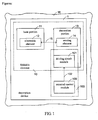
- FIG 1 is a functional block diagram showing a decoration device according to one embodiment of the invention.
- FIG. 2A to FIG. 2D are schematic diagrams showing a decoration device for a floor lamp according to one embodiment of the invention.
- FIG. 3A to FIG. 3C are schematic diagrams showing a decoration device for a heating fragrance device according to one embodiment of the invention.
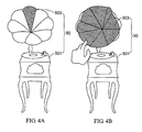
- FIG. 4A and FIG. 4B are schematic diagrams showing a decoration device for a revival phonograph according to one embodiment of the invention.
- This invention provides a decoration device capable of achieving a visual effect, a practicable effect, and a space storage effect at the same time to improve the problem in the prior art that the decoration device is lack of functionality.
- the decoration device in the invention can be disposed at a wall surface where conventional wallpaper is attached to, and it can also be present via a paper folding structure or a three-dimensional book, further to extend applications to different kinds of plane structures.
- FIG. 1 is a functional block diagram showing a decoration device according to one embodiment of the invention.
- a decoration device 1 is disposed at a flat surface 16 and includes a foldable element 10.
- the foldable element 10 can include a planar base portion 11 attached to the flat surface 16 and a decoration portion 13 detached from the flat surface 16.
- the planar base portion 11 can be made of a first sheet (not shown).
- the decoration portion 13 can be folded from at least one second sheet (not shown) and be unfolded or folded relative to the base portion 11 by an external force.
- a material of the sheets can be selected from the group consisting of paper, a plastic material, an adhering material, and a fiber material according to needs.
- the foldable element 10 of the decoration device 1 can change between a folded state and an unfolded state by the external force, and the decoration portion 13 is folded when the foldable element 10 is in the folded state.
- the decoration device 1 achieves needed functions via two circuit elements.
- One circuit element is an electronic element 12 connected with the planar base portion 11, and the other circuit element is a sensing element 14 disposed at the decoration portion 13 and connected with the electronic element 12.
- the former provides a main circuit function of the decoration device 1, and the latter controls the former by sensing a status of the foldable element 10.
- the decoration device 1 can further include a supporting assembly (not shown) connected with the planar base portion 11 and the decoration portion 13 to support the foldable element 10 to be fixed to one intermediate state between the folded state and the unfolded state.
- a user When operating the decoration device 1, a user first exerts external force to allow the decoration portion 13 to generate a status change.
- the status change triggers the sensing element 14 to allow the sensing element 14 to transmit a control signal 15 to the electronic element 12, thereby controlling the electronic element 12 to perform an operation function of the decoration device 1.
- the external force can be directly generated by the user or by a third portion 103.
- the third portion 103 can include an external control module 100 and a driving circuit module 101.
- the external control module 100 is used as an interface for the user to operate the decoration device 1, and it can generate a driving signal 102 to trigger a driving circuit module 101 of the decoration portion 13.
- the driving circuit module 101 further generates the external force to allow the decoration portion 13 to change the status.
- FIG. 2A to FIG. 2D are schematic diagrams according to a first preferred embodiment of the invention.
- a decoration device 2 with a floor lamp function is described.
- FIG. 2A is a partial side view showing the decoration device 2 with the floor lamp function.
- a foldable element 20 of the decoration device 2 includes a decoration portion 25 and a planar base portion 26.
- the planar base portion 26 is a wall sticker attached to a wall surface 3 and is made of a first sheet.
- the first sheet can be selected from the group consisting of paper, a plastic material, an adhering material, and a fiber material.
- the decoration portion 25 is connected with the planar base portion 26 and is folded from a second sheet.
- the decoration portion 25 can change between a folded state and an unfolded state by the external force, and the decoration portion 25 is folded when the foldable element 20 is in the folded state.
- the decoration portion 25 presents a trapezoidal plane when the foldable element 20 is in the folded state.
- a plurality of folding lines are further disposed between an upper side and a lower side of the decoration portion 25, and the decoration portion 25 can be pulled up relative to the planar base portion 26 by the external force and be unfolded along the folding lines to form a shade.
- the decoration device 2 further includes a light emitting diode 23, a lighting circuit module 22, a switch 24 connected with the wall surface 3, and a wire 27 connected with the switch 24.
- the light emitting diode 23 can be disposed between the planar base portion 26 and the decoration portion 25, and the lighting circuit module 22, the switch 24, and the wire 27 can be embedded into the wall surface 3 or be fastened between the planar base portion 26 and the wall surface 3 for aesthetic.
- the invention is not limited thereto.
- the elements may also be disposed on the planar base portion 26 to be exposed outside.
- the decoration device 2 further includes a sensing element 21 disposed at the decoration portion 25 for sensing a status change of the foldable element 20, thereby allowing the status change to correspond to a control signal 29 transmitted to the lighting circuit module 22.
- a sensing element 21 disposed at the decoration portion 25 for sensing a status change of the foldable element 20, thereby allowing the status change to correspond to a control signal 29 transmitted to the lighting circuit module 22. It mans that, a user can pull up the decoration portion 25 along the folding lines on the decoration portion 25 when the user wants to adjust brightness of the decoration device 2 with the floor lamp function. And then, the external force can trigger the sensing element 21 at the decoration portion 25.
- the sensing element 21 converts the adjustment to strength of a signal, and then it transmits the control signal 29 to the lighting circuit module 22, further to adjust the brightness of the decoration device 2 with the floor lamp function.
- the methods of the adjustment include a direct force exertion control and an external control.
- the lighting circuit module 22 is controlled via the sensing element 21.
- the direct force exertion control is that the user directly adjusts the decoration portion 25 manually.
- the external control is that the user uses a remote switch or a key switch in cooperation with a driving module (not shown) additionally disposed in the decoration portion 25.
- the driving module drives the decoration portion 25 to change a status further to trigger the sensing element 21.
- FIG. 2B to FIG 2D are side and front schematic diagrams showing the decoration device 2 with the floor lamp function in FIG. 2A in operation.
- the decoration device 2 is attached to the wall surface 3 via the rod-shaped planar base portion 26.
- the decoration portion 25 is folded when the foldable element 20 is in the folded state, and an electronic element (the light emitting diode 23 in this embodiment) of the decoration device 2 is in an off state.
- the decoration portion 25 is stored to be attached to the wall surface 3.
- FIG. 2C the decoration portion 25 is pulled up a little when the foldable element 20 is between the folded state and the unfolded state, and the brightness of the decoration device 2 is slight.
- the side surface of the decoration portion 25 is more protrudent than that in FIG. 2B .
- the decoration portion 25 is unfolded to the greatest when the foldable element 20 is in the unfolded state, which represents that the brightness of the decoration device 2 is adjusted to the greatest. At that moment, the unfolded extent of the decoration portion 25 in the side view is the greatest.
- FIG. 3A to FIG. 3C are schematic diagrams showing a decoration device with a heating fragrance function according to a second preferred embodiment of the invention.
- the decoration device is attached to a wall surface 3 via a planar base portion 401 with a dressing table appearance and cooperates with a scent diffusing circuit module (not shown), which looks as a heating fragrance device disposed at a dressing table in vision.
- a decoration portion 403 connected with the planar base portion 401 includes a plurality of second sheets, and each of the second sheets is flipping connected with the planar base portion 401.
- the decoration portion 403 is folded to present a planar vase shape when the foldable element 40 is in a folded state, and the decoration portion 403 can be flipped to be unfolded when the foldable element 40 is in an unfolded state.
- a sensing element is disposed in the decoration portion 403, and it can control the scent diffusing circuit module according to the unfolded extent of the decoration portion 403 after the decoration portion 403 is flipped.
- the decoration portion 403 is folded to be parallel to the wall surface when the foldable element 40 is in the folded state. At that moment, the scent diffusing circuit module does not work.
- the decoration portion 403 is partly unfolded when the foldable element 40 is between the folded state and the unfolded state. At that moment, the decoration device with the heating fragrance function begins to diffuse fragrance, and the heating temperature of the scent diffusing circuit module is not the highest.
- the decoration portion 403 is totally unfolded when the foldable element 40 is in the unfolded state. The sensing element in the decoration portion 403 controls the heating power of the scent diffusing circuit module to achieve the highest, and the diffusing rate of essential oil also achieves the greatest.
- FIG. 4A and FIG. 4B are schematic diagrams showing a decoration device for a revival phonograph according to a third preferred embodiment of the invention.
- a planar base portion 501 is a wall sticker with a revival phonograph appearance for being adhered to a wall surface
- a decoration portion 503 is a folding structure.
- the decoration portion 503 has a plurality of folding lines, such that the decoration portion 503 presents a pyramidal appearance when the foldable element 50 is in a folded state, and the pyramidal decoration portion 503 can be unfolded by the external force to present a trumpet-shaped appearance when the foldable element 50 is in an unfolded state.
- a sensing element located in the decoration portion 503 can sense adjustment of the decoration portion 503 by the external force, and it can transmit a corresponding control signal to an audio playing circuit module at the planar base portion 501 according to the unfolded extent of the decoration portion 503.
- the volume is the smallest, and the decoration portion 503 is folded to be attached to the wall surface.
- the volume is adjusted to the greatest, and the decoration portion 503 is also unfolded to the greatest.
- An audio playing circuit module, a radio circuit module, an interphone circuit module, or an answering circuit module with a loudspeaker function can also be disposed at a wall surface or a cupboard surface to provide a decoration device with a storage function.
- the electronic element can be controlled further to provide a practical circuit function for the decoration device.
- sensing elements such as a pressure sensing element, a displacement sensing element, a motion sensing element, a position sensing element, or a bend sensing element
- the electronic element can be controlled further to provide a practical circuit function for the decoration device.
- the original wallpaper with one single function aiming at the visual effect can be improved, and further the objective of this invention combined with aesthetic, practicality, and a space storage effect can be achieved.
Landscapes
- Telephone Set Structure (AREA)
- Toys (AREA)
- Illuminated Signs And Luminous Advertising (AREA)
Description
- This application claims priority on Patent Application No(s).
098128875 - This invention relates to a decoration device and, more particularly, to a decoration device incorporating an electronic element.
- A decoration device (such as wallpaper and wall sticker) generally for improving environmental aesthetic mostly has changes in color and material. Specially, wallpaper may cooperate with brightness of lamps to achieve an effect, or wallpaper with a three-dimensional design instead of a plane design may be used. However, they are all stereotypes aiming at the visual effect. Some wallpaper with additional functions, such as wallpaper with an electromagnetic shielding function, achieves the electromagnetic shielding function by improving materials.
- As a general plane device is considered, at present, there are an interactive window curtain combined with man-machine interaction such as scene wallpaper and a device disposed at a wall surface and capable of interacting with users. As the interactive window curtain is considered, a frame similar to outside views is embedded in a wall surface or a window frame surface, and the frame has a light control and sound switching function. Thereby, although people stay in the room, they can feel as staying in the outside views with different climate and environment. As the latter device is considered, the device is essentially a computer which is embedded into the wall surface and is capable of interacting with the users. The device cooperates with a frame or a support and a material to allow a general exposed computer screen to pretend to one portion of the wall or furniture. However, the objective of the above design is to hide the originally exposed computer to provide a protecting function instead of providing actual functional operation.
GB 2 295 044 - This invention, defined by the appended claims, provides a decoration device including a foldable element, an electronic element, and a sensing element. The foldable element includes a planar base portion and a decoration portion. The decoration portion is connected with the planar base portion. The foldable element changes between a folded state and an unfolded state by an external force. The decoration portion is folded when the foldable element is in the folded state. The electronic element is connected with the planar base portion. The sensing element senses a status of the foldable element to control the electronic element.
- According to the invention, the decoration portion further includes a driving circuit module capable of generating the external force to allow the foldable element to change to the folded state or the unfolded state.
- In one embodiment of the invention, the planar base portion may be a first sheet, and the first sheet may be selected from the group consisting of paper, a plastic material, an adhering material, and a fiber material.
- In one embodiment of the invention, the planar base portion of the foldable element may be a wall sticker.
- In one embodiment of the invention, the decoration device may further include a supporting assembly connected with the planar base portion and the decoration portion to support the foldable element to be fixed to one intermediate state between the folded state and the unfolded state.
- In one embodiment of the invention, the decoration portion may be folded from at least one second sheet and be folded or unfolded relative to the planar base portion by the external force, and the second sheet may be selected from the group consisting of paper, a plastic material, a fiber material, and a composite material.
- In one embodiment of the invention, the planar base portion of the foldable element may be rod-shaped, and the decoration portion may be connected with one end of the base portion. The decoration portion may be a trapezoid plane when the foldable element is in the folded state, and a plurality of folding lines may be further disposed between an upper side and a lower side of the decoration portion so that the decoration portion may be pulled up relative to the planar base portion by the external force and be unfolded along the folding lines to form a shade.
- In one embodiment of the invention, the decoration portion of the foldable element may include a plurality of second sheets, and the decoration portion may be flipping connected with the planar base portion. the decoration portion is folded to present a planar vase shape when the foldable element is in the folded state, and the decoration portion is capable of being flipped to be unfolded when the foldable element is in the unfolded state.
- In one embodiment of the invention, the decoration portion of the foldable element may have a plurality of folding lines to allow the decoration portion to present a pyramidal appearance when the foldable element is in the folded state, and the decoration portion may be unfolded by the external force to present a trumpet-shaped appearance when the foldable element is in the unfolded state.
- In one embodiment of the invention, the electronic element may be a lighting circuit module, a scent diffusing circuit module, an audio playing circuit module, a radio circuit module, an interphone circuit module, or an answering machine circuit module.
- In one embodiment of the invention, the sensing element may be a pressure sensing element, a displacement sensing element, a motion sensing element, a position sensing element, or a bend sensing element.
- In one embodiment of the invention, the driving circuit module may be a motor module.
- In one embodiment of the invention, the decoration device may further include an external control module capable of outputting a driving signal to the driving circuit module.
- In one embodiment of the invention, the external control module may be a remote switch or a key switch.
- These and other features, aspects, and advantages of the present invention will become better understood with regard to the following description, appended claims, and accompanying drawings.
-
FIG 1 is a functional block diagram showing a decoration device according to one embodiment of the invention; -
FIG. 2A to FIG. 2D are schematic diagrams showing a decoration device for a floor lamp according to one embodiment of the invention; -
FIG. 3A to FIG. 3C are schematic diagrams showing a decoration device for a heating fragrance device according to one embodiment of the invention; and -
FIG. 4A and FIG. 4B are schematic diagrams showing a decoration device for a revival phonograph according to one embodiment of the invention. - This invention provides a decoration device capable of achieving a visual effect, a practicable effect, and a space storage effect at the same time to improve the problem in the prior art that the decoration device is lack of functionality. In addition, the decoration device in the invention can be disposed at a wall surface where conventional wallpaper is attached to, and it can also be present via a paper folding structure or a three-dimensional book, further to extend applications to different kinds of plane structures.
-
FIG. 1 is a functional block diagram showing a decoration device according to one embodiment of the invention. Adecoration device 1 is disposed at aflat surface 16 and includes afoldable element 10. Thefoldable element 10 can include aplanar base portion 11 attached to theflat surface 16 and adecoration portion 13 detached from theflat surface 16. Theplanar base portion 11 can be made of a first sheet (not shown). Thedecoration portion 13 can be folded from at least one second sheet (not shown) and be unfolded or folded relative to thebase portion 11 by an external force. A material of the sheets can be selected from the group consisting of paper, a plastic material, an adhering material, and a fiber material according to needs. - The
foldable element 10 of thedecoration device 1 can change between a folded state and an unfolded state by the external force, and thedecoration portion 13 is folded when thefoldable element 10 is in the folded state. Thedecoration device 1 achieves needed functions via two circuit elements. One circuit element is anelectronic element 12 connected with theplanar base portion 11, and the other circuit element is asensing element 14 disposed at thedecoration portion 13 and connected with theelectronic element 12. The former provides a main circuit function of thedecoration device 1, and the latter controls the former by sensing a status of thefoldable element 10. Thedecoration device 1 can further include a supporting assembly (not shown) connected with theplanar base portion 11 and thedecoration portion 13 to support thefoldable element 10 to be fixed to one intermediate state between the folded state and the unfolded state. - When operating the
decoration device 1, a user first exerts external force to allow thedecoration portion 13 to generate a status change. The status change triggers thesensing element 14 to allow thesensing element 14 to transmit acontrol signal 15 to theelectronic element 12, thereby controlling theelectronic element 12 to perform an operation function of thedecoration device 1. The external force can be directly generated by the user or by athird portion 103. Thethird portion 103 can include anexternal control module 100 and adriving circuit module 101. Theexternal control module 100 is used as an interface for the user to operate thedecoration device 1, and it can generate adriving signal 102 to trigger adriving circuit module 101 of thedecoration portion 13. The drivingcircuit module 101 further generates the external force to allow thedecoration portion 13 to change the status. - Besides the basic description of the functional block diagram, three preferred embodiments of the invention are described.
FIG. 2A to FIG. 2D are schematic diagrams according to a first preferred embodiment of the invention. In the first embodiment, adecoration device 2 with a floor lamp function is described.FIG. 2A is a partial side view showing thedecoration device 2 with the floor lamp function. Afoldable element 20 of thedecoration device 2 includes adecoration portion 25 and aplanar base portion 26. In the embodiment, theplanar base portion 26 is a wall sticker attached to awall surface 3 and is made of a first sheet. The first sheet can be selected from the group consisting of paper, a plastic material, an adhering material, and a fiber material. - The
decoration portion 25 is connected with theplanar base portion 26 and is folded from a second sheet. Thedecoration portion 25 can change between a folded state and an unfolded state by the external force, and thedecoration portion 25 is folded when thefoldable element 20 is in the folded state. In the embodiment, thedecoration portion 25 presents a trapezoidal plane when thefoldable element 20 is in the folded state. A plurality of folding lines are further disposed between an upper side and a lower side of thedecoration portion 25, and thedecoration portion 25 can be pulled up relative to theplanar base portion 26 by the external force and be unfolded along the folding lines to form a shade. - In addition, the
decoration device 2 further includes alight emitting diode 23, alighting circuit module 22, aswitch 24 connected with thewall surface 3, and awire 27 connected with theswitch 24. Thelight emitting diode 23 can be disposed between theplanar base portion 26 and thedecoration portion 25, and thelighting circuit module 22, theswitch 24, and thewire 27 can be embedded into thewall surface 3 or be fastened between theplanar base portion 26 and thewall surface 3 for aesthetic. However, the invention is not limited thereto. The elements may also be disposed on theplanar base portion 26 to be exposed outside. - The
decoration device 2 further includes asensing element 21 disposed at thedecoration portion 25 for sensing a status change of thefoldable element 20, thereby allowing the status change to correspond to acontrol signal 29 transmitted to thelighting circuit module 22. It mans that, a user can pull up thedecoration portion 25 along the folding lines on thedecoration portion 25 when the user wants to adjust brightness of thedecoration device 2 with the floor lamp function. And then, the external force can trigger thesensing element 21 at thedecoration portion 25. Thesensing element 21 converts the adjustment to strength of a signal, and then it transmits thecontrol signal 29 to thelighting circuit module 22, further to adjust the brightness of thedecoration device 2 with the floor lamp function. - Further, when the user wants to adjust the brightness of the
decoration device 2 with the floor lamp function, the methods of the adjustment include a direct force exertion control and an external control. However, no matter what kind of adjustment is used, thelighting circuit module 22 is controlled via thesensing element 21. The direct force exertion control is that the user directly adjusts thedecoration portion 25 manually. The external control is that the user uses a remote switch or a key switch in cooperation with a driving module (not shown) additionally disposed in thedecoration portion 25. When the user controls the remote switch or the key switch, the driving module drives thedecoration portion 25 to change a status further to trigger thesensing element 21. -
FIG. 2B to FIG 2D are side and front schematic diagrams showing thedecoration device 2 with the floor lamp function inFIG. 2A in operation. Thedecoration device 2 is attached to thewall surface 3 via the rod-shapedplanar base portion 26. InFIG. 2B , thedecoration portion 25 is folded when thefoldable element 20 is in the folded state, and an electronic element (thelight emitting diode 23 in this embodiment) of thedecoration device 2 is in an off state. At that moment, according to the side view inFIG. 2B , thedecoration portion 25 is stored to be attached to thewall surface 3. InFIG. 2C , thedecoration portion 25 is pulled up a little when thefoldable element 20 is between the folded state and the unfolded state, and the brightness of thedecoration device 2 is slight. According to the side view inFIG. 2C , the side surface of thedecoration portion 25 is more protrudent than that inFIG. 2B . InFIG. 2D , thedecoration portion 25 is unfolded to the greatest when thefoldable element 20 is in the unfolded state, which represents that the brightness of thedecoration device 2 is adjusted to the greatest. At that moment, the unfolded extent of thedecoration portion 25 in the side view is the greatest. - Besides the floor lamp application, the decoration device in the invention can also be combined with other functional circuits.
FIG. 3A to FIG. 3C are schematic diagrams showing a decoration device with a heating fragrance function according to a second preferred embodiment of the invention. In the second preferred embodiment, the decoration device is attached to awall surface 3 via aplanar base portion 401 with a dressing table appearance and cooperates with a scent diffusing circuit module (not shown), which looks as a heating fragrance device disposed at a dressing table in vision. - A
decoration portion 403 connected with theplanar base portion 401 includes a plurality of second sheets, and each of the second sheets is flipping connected with theplanar base portion 401. Thedecoration portion 403 is folded to present a planar vase shape when thefoldable element 40 is in a folded state, and thedecoration portion 403 can be flipped to be unfolded when thefoldable element 40 is in an unfolded state. A sensing element is disposed in thedecoration portion 403, and it can control the scent diffusing circuit module according to the unfolded extent of thedecoration portion 403 after thedecoration portion 403 is flipped. - In
FIG. 3A , thedecoration portion 403 is folded to be parallel to the wall surface when thefoldable element 40 is in the folded state. At that moment, the scent diffusing circuit module does not work. InFIG. 3B , thedecoration portion 403 is partly unfolded when thefoldable element 40 is between the folded state and the unfolded state. At that moment, the decoration device with the heating fragrance function begins to diffuse fragrance, and the heating temperature of the scent diffusing circuit module is not the highest. InFIG. 3C , thedecoration portion 403 is totally unfolded when thefoldable element 40 is in the unfolded state. The sensing element in thedecoration portion 403 controls the heating power of the scent diffusing circuit module to achieve the highest, and the diffusing rate of essential oil also achieves the greatest. -
FIG. 4A and FIG. 4B are schematic diagrams showing a decoration device for a revival phonograph according to a third preferred embodiment of the invention. Aplanar base portion 501 is a wall sticker with a revival phonograph appearance for being adhered to a wall surface, and adecoration portion 503 is a folding structure. Thedecoration portion 503 has a plurality of folding lines, such that thedecoration portion 503 presents a pyramidal appearance when thefoldable element 50 is in a folded state, and thepyramidal decoration portion 503 can be unfolded by the external force to present a trumpet-shaped appearance when thefoldable element 50 is in an unfolded state. A sensing element located in thedecoration portion 503 can sense adjustment of thedecoration portion 503 by the external force, and it can transmit a corresponding control signal to an audio playing circuit module at theplanar base portion 501 according to the unfolded extent of thedecoration portion 503. The greater the unfolded extent of thedecoration portion 503 is, the greater the playing volume is. InFIG. 4A , the volume is the smallest, and thedecoration portion 503 is folded to be attached to the wall surface. InFIG. 4B , the volume is adjusted to the greatest, and thedecoration portion 503 is also unfolded to the greatest. - An audio playing circuit module, a radio circuit module, an interphone circuit module, or an answering circuit module with a loudspeaker function can also be disposed at a wall surface or a cupboard surface to provide a decoration device with a storage function.
- To sum up, conventional wallpaper has a simple and definite function, that is, for decoration. Therefore, the visual feeling is considered as a focal point, and the methods are all classified to motionless feeling changes without practical effects. In the invention, the conventional thought that the wallpaper is used for appreciation instead of the practical effects is thrown away, and the wallpaper has an electronic device function, further to be widely disposed at different flat surfaces. Besides the applications in the above preferred embodiments, this invention can have a wide application scope. As long as according to the structures or shapes of the decoration portion in cooperation with different types of sensing elements such as a pressure sensing element, a displacement sensing element, a motion sensing element, a position sensing element, or a bend sensing element, the electronic element can be controlled further to provide a practical circuit function for the decoration device. Thus, the original wallpaper with one single function aiming at the visual effect can be improved, and further the objective of this invention combined with aesthetic, practicality, and a space storage effect can be achieved.
Claims (12)
- A decoration device, the decoration device comprising:a foldable element including:a planar base portion; anda decoration portion connected with the planar base portion, wherein the foldable element changes between a folded state and an unfolded state by an external force, and the decoration portion is folded when the foldable element is in the folded state;an electronic element connected with the planar base portion; anda sensing element sensing a status of the foldable element to control the electronic element, characterized in that the decoration portion further comprises a driving circuit module capable of generating the external force to allow the foldable element to change to the folded state or the unfolded state.
- The decoration device according to claim 1, wherein the planar base portion is a first sheet, and the first sheet is selected from the group consisting of paper, a plastic material, an adhering material, and a fiber material.
- The decoration device according to claim 1 or 2, further comprising a supporting assembly connected with the planar base portion and the decoration portion to support the foldable element to be fixed to one intermediate state between the folded state and the unfolded state.
- The decoration device according to an one of claims 1 to 3, wherein the decoration portion is folded from at least one second sheet and is folded or unfolded relative to the planar base portion by the external force, and the second sheet is selected from the group consisting of paper, a plastic material, a fiber material, and a composite material.
- The decoration device according to claim 4, the planar base portion of the foldable element being rod-shaped, and the decoration portion being connected with one end of the planar base portion, wherein the decoration portion is a trapezoid plane when the foldable element is in the folded state, a plurality of folding lines are further disposed between an upper side and a lower side of the decoration portion so that the decoration portion is pulled up relative to the planar base portion by the external force and is unfolded along the folding lines to form a shade.
- The decoration device according to claim 4, the decoration portion of the foldable element including a plurality of the second sheets, the decoration portion being flipping connected with the planar base portion, wherein the decoration portion is folded to present a planar vase shape when the foldable element is in the folded state, and the decoration portion is capable of being flipped to be unfolded when the foldable element is in the unfolded state.
- The decoration device according to claim 4, the decoration portion of the foldable element having a plurality of folding lines to allow the decoration portion to present a pyramidal appearance when the foldable element is in the folded state, the decoration portion being capable of being unfolded by the external force to present a trumpet-shaped appearance when the foldable element is in the unfolded state.
- The decoration device according to any one of claims 1 to 7, wherein the electronic element is a lighting circuit module, a scent diffusing circuit module, an audio playing circuit module, a radio circuit module, an interphone circuit module, or an answering machine circuit module.
- The decoration device according to any one of claims 1 to 8, wherein the sensing element is a pressure sensing element, a displacement sensing element, a motion sensing element, a position sensing element, or a bend sensing element.
- The decoration device according to any one of claims 1 to 9, wherein the driving circuit module is a motor module.
- The decoration device according to any one of claims 1 to 10, further comprising an external control module capable of outputting a driving signal to the driving circuit module.
- The decoration device according to claim 11, wherein the external control module is a remote switch or a key switch.
Applications Claiming Priority (1)
| Application Number | Priority Date | Filing Date | Title |
|---|---|---|---|
| TW98128875A TWI384176B (en) | 2009-08-27 | 2009-08-27 | Decoration apparatus |
Publications (2)
| Publication Number | Publication Date |
|---|---|
| EP2295265A1 EP2295265A1 (en) | 2011-03-16 |
| EP2295265B1 true EP2295265B1 (en) | 2013-06-05 |
Family
ID=43481008
Family Applications (1)
| Application Number | Title | Priority Date | Filing Date |
|---|---|---|---|
| EP20100006834 Active EP2295265B1 (en) | 2009-08-27 | 2010-07-01 | Folding decoration device |
Country Status (2)
| Country | Link |
|---|---|
| EP (1) | EP2295265B1 (en) |
| TW (1) | TWI384176B (en) |
Family Cites Families (6)
| Publication number | Priority date | Publication date | Assignee | Title |
|---|---|---|---|---|
| GB2295044B (en) * | 1994-11-14 | 1998-12-09 | Andrew Mcleod Gibb | Compact disc apparatus |
| JP2005204812A (en) * | 2004-01-21 | 2005-08-04 | Unoshi Kk | Ornament |
| TW200631549A (en) * | 2005-03-15 | 2006-09-16 | Chang-Ming Yang | Wearing article |
| JP2008055879A (en) * | 2006-09-04 | 2008-03-13 | Sanwa Jitsugyo Kk | Three-dimensional illumination card |
| TWI329504B (en) * | 2007-10-23 | 2010-09-01 | Univ Nat Formosa | Intelligent opto-electrical curtain |
| US20090126239A1 (en) * | 2007-11-20 | 2009-05-21 | Timothy Clegg | Motorized action card |
-
2009
- 2009-08-27 TW TW98128875A patent/TWI384176B/en active
-
2010
- 2010-07-01 EP EP20100006834 patent/EP2295265B1/en active Active
Also Published As
| Publication number | Publication date |
|---|---|
| TW201107663A (en) | 2011-03-01 |
| TWI384176B (en) | 2013-02-01 |
| EP2295265A1 (en) | 2011-03-16 |
Similar Documents
| Publication | Publication Date | Title |
|---|---|---|
| USD549724S1 (en) | Computer generated image for a display panel or screen | |
| USD549725S1 (en) | Computer generated image for a display panel or screen | |
| CN102422423B (en) | Piece of furniture covered with a flexible screen | |
| USD550242S1 (en) | Computer generated image for a display panel or screen | |
| WO2019082399A1 (en) | Operation display panel-equipped product | |
| RU2697619C1 (en) | Combined loudspeaker and lamp and combination method thereof | |
| USD582935S1 (en) | Image display for a mobile phone | |
| TWD129210S1 (en) | Portable front projection screen | |
| TR201615884A2 (en) | ILLUMINATED SPEAKER | |
| TW201007529A (en) | Programmable user interface device for controlling an electrical power supplied to an electrical consumer | |
| EP2295265A1 (en) | Folding decoration device | |
| CN202551268U (en) | Speaker mesh enclosure assembly provided with display function | |
| US6502339B1 (en) | Shadow display device | |
| CN205069022U (en) | Display panel and electric appliance comprising same | |
| CN205090268U (en) | A mirror light with TV function | |
| CN101992652B (en) | Decoration assembly | |
| CN207744958U (en) | Multifunctional mirror | |
| CN103279284A (en) | Touch display wall | |
| CN205090353U (en) | A multifunctional mirror light | |
| CN202619090U (en) | Touch screen control mirror surface | |
| CN203721125U (en) | Touch switch panel capable of arbitrarily replacing photo pictures, and casing | |
| CN203710670U (en) | Game machine | |
| CN101994931B (en) | lamps | |
| CN209511941U (en) | A customizable multifunctional mosaic photo frame light | |
| JP2023051660A (en) | Display device |
Legal Events
| Date | Code | Title | Description |
|---|---|---|---|
| PUAI | Public reference made under article 153(3) epc to a published international application that has entered the european phase |
Free format text: ORIGINAL CODE: 0009012 |
|
| AK | Designated contracting states |
Kind code of ref document: A1 Designated state(s): AL AT BE BG CH CY CZ DE DK EE ES FI FR GB GR HR HU IE IS IT LI LT LU LV MC MK MT NL NO PL PT RO SE SI SK SM TR |
|
| AX | Request for extension of the european patent |
Extension state: BA ME RS |
|
| 17P | Request for examination filed |
Effective date: 20110906 |
|
| 17Q | First examination report despatched |
Effective date: 20120703 |
|
| GRAP | Despatch of communication of intention to grant a patent |
Free format text: ORIGINAL CODE: EPIDOSNIGR1 |
|
| GRAS | Grant fee paid |
Free format text: ORIGINAL CODE: EPIDOSNIGR3 |
|
| GRAA | (expected) grant |
Free format text: ORIGINAL CODE: 0009210 |
|
| RAP1 | Party data changed (applicant data changed or rights of an application transferred) |
Owner name: PEGATRON CORPORATION |
|
| RIN1 | Information on inventor provided before grant (corrected) |
Inventor name: LEE, CHIA-YING Inventor name: LU, CHIA-EN |
|
| AK | Designated contracting states |
Kind code of ref document: B1 Designated state(s): AL AT BE BG CH CY CZ DE DK EE ES FI FR GB GR HR HU IE IS IT LI LT LU LV MC MK MT NL NO PL PT RO SE SI SK SM TR |
|
| REG | Reference to a national code |
Ref country code: GB Ref legal event code: FG4D |
|
| REG | Reference to a national code |
Ref country code: CH Ref legal event code: EP |
|
| REG | Reference to a national code |
Ref country code: AT Ref legal event code: REF Ref document number: 615425 Country of ref document: AT Kind code of ref document: T Effective date: 20130615 |
|
| REG | Reference to a national code |
Ref country code: IE Ref legal event code: FG4D |
|
| REG | Reference to a national code |
Ref country code: DE Ref legal event code: R096 Ref document number: 602010007454 Country of ref document: DE Effective date: 20130801 |
|
| REG | Reference to a national code |
Ref country code: NL Ref legal event code: T3 |
|
| REG | Reference to a national code |
Ref country code: AT Ref legal event code: MK05 Ref document number: 615425 Country of ref document: AT Kind code of ref document: T Effective date: 20130605 |
|
| PG25 | Lapsed in a contracting state [announced via postgrant information from national office to epo] |
Ref country code: FI Free format text: LAPSE BECAUSE OF FAILURE TO SUBMIT A TRANSLATION OF THE DESCRIPTION OR TO PAY THE FEE WITHIN THE PRESCRIBED TIME-LIMIT Effective date: 20130605 Ref country code: NO Free format text: LAPSE BECAUSE OF FAILURE TO SUBMIT A TRANSLATION OF THE DESCRIPTION OR TO PAY THE FEE WITHIN THE PRESCRIBED TIME-LIMIT Effective date: 20130905 Ref country code: ES Free format text: LAPSE BECAUSE OF FAILURE TO SUBMIT A TRANSLATION OF THE DESCRIPTION OR TO PAY THE FEE WITHIN THE PRESCRIBED TIME-LIMIT Effective date: 20130916 Ref country code: SI Free format text: LAPSE BECAUSE OF FAILURE TO SUBMIT A TRANSLATION OF THE DESCRIPTION OR TO PAY THE FEE WITHIN THE PRESCRIBED TIME-LIMIT Effective date: 20130605 Ref country code: SE Free format text: LAPSE BECAUSE OF FAILURE TO SUBMIT A TRANSLATION OF THE DESCRIPTION OR TO PAY THE FEE WITHIN THE PRESCRIBED TIME-LIMIT Effective date: 20130605 Ref country code: LT Free format text: LAPSE BECAUSE OF FAILURE TO SUBMIT A TRANSLATION OF THE DESCRIPTION OR TO PAY THE FEE WITHIN THE PRESCRIBED TIME-LIMIT Effective date: 20130605 Ref country code: AT Free format text: LAPSE BECAUSE OF FAILURE TO SUBMIT A TRANSLATION OF THE DESCRIPTION OR TO PAY THE FEE WITHIN THE PRESCRIBED TIME-LIMIT Effective date: 20130605 Ref country code: GR Free format text: LAPSE BECAUSE OF FAILURE TO SUBMIT A TRANSLATION OF THE DESCRIPTION OR TO PAY THE FEE WITHIN THE PRESCRIBED TIME-LIMIT Effective date: 20130906 |
|
| REG | Reference to a national code |
Ref country code: LT Ref legal event code: MG4D |
|
| PG25 | Lapsed in a contracting state [announced via postgrant information from national office to epo] |
Ref country code: BG Free format text: LAPSE BECAUSE OF FAILURE TO SUBMIT A TRANSLATION OF THE DESCRIPTION OR TO PAY THE FEE WITHIN THE PRESCRIBED TIME-LIMIT Effective date: 20130905 Ref country code: HR Free format text: LAPSE BECAUSE OF FAILURE TO SUBMIT A TRANSLATION OF THE DESCRIPTION OR TO PAY THE FEE WITHIN THE PRESCRIBED TIME-LIMIT Effective date: 20130605 |
|
| PG25 | Lapsed in a contracting state [announced via postgrant information from national office to epo] |
Ref country code: LV Free format text: LAPSE BECAUSE OF FAILURE TO SUBMIT A TRANSLATION OF THE DESCRIPTION OR TO PAY THE FEE WITHIN THE PRESCRIBED TIME-LIMIT Effective date: 20130605 |
|
| PG25 | Lapsed in a contracting state [announced via postgrant information from national office to epo] |
Ref country code: BE Free format text: LAPSE BECAUSE OF FAILURE TO SUBMIT A TRANSLATION OF THE DESCRIPTION OR TO PAY THE FEE WITHIN THE PRESCRIBED TIME-LIMIT Effective date: 20130605 Ref country code: IS Free format text: LAPSE BECAUSE OF FAILURE TO SUBMIT A TRANSLATION OF THE DESCRIPTION OR TO PAY THE FEE WITHIN THE PRESCRIBED TIME-LIMIT Effective date: 20131005 Ref country code: CZ Free format text: LAPSE BECAUSE OF FAILURE TO SUBMIT A TRANSLATION OF THE DESCRIPTION OR TO PAY THE FEE WITHIN THE PRESCRIBED TIME-LIMIT Effective date: 20130605 Ref country code: SK Free format text: LAPSE BECAUSE OF FAILURE TO SUBMIT A TRANSLATION OF THE DESCRIPTION OR TO PAY THE FEE WITHIN THE PRESCRIBED TIME-LIMIT Effective date: 20130605 Ref country code: PT Free format text: LAPSE BECAUSE OF FAILURE TO SUBMIT A TRANSLATION OF THE DESCRIPTION OR TO PAY THE FEE WITHIN THE PRESCRIBED TIME-LIMIT Effective date: 20131007 Ref country code: EE Free format text: LAPSE BECAUSE OF FAILURE TO SUBMIT A TRANSLATION OF THE DESCRIPTION OR TO PAY THE FEE WITHIN THE PRESCRIBED TIME-LIMIT Effective date: 20130605 |
|
| PG25 | Lapsed in a contracting state [announced via postgrant information from national office to epo] |
Ref country code: RO Free format text: LAPSE BECAUSE OF FAILURE TO SUBMIT A TRANSLATION OF THE DESCRIPTION OR TO PAY THE FEE WITHIN THE PRESCRIBED TIME-LIMIT Effective date: 20130605 Ref country code: PL Free format text: LAPSE BECAUSE OF FAILURE TO SUBMIT A TRANSLATION OF THE DESCRIPTION OR TO PAY THE FEE WITHIN THE PRESCRIBED TIME-LIMIT Effective date: 20130605 |
|
| PG25 | Lapsed in a contracting state [announced via postgrant information from national office to epo] |
Ref country code: MC Free format text: LAPSE BECAUSE OF FAILURE TO SUBMIT A TRANSLATION OF THE DESCRIPTION OR TO PAY THE FEE WITHIN THE PRESCRIBED TIME-LIMIT Effective date: 20130605 |
|
| PLBE | No opposition filed within time limit |
Free format text: ORIGINAL CODE: 0009261 |
|
| STAA | Information on the status of an ep patent application or granted ep patent |
Free format text: STATUS: NO OPPOSITION FILED WITHIN TIME LIMIT |
|
| REG | Reference to a national code |
Ref country code: IE Ref legal event code: MM4A |
|
| PG25 | Lapsed in a contracting state [announced via postgrant information from national office to epo] |
Ref country code: DK Free format text: LAPSE BECAUSE OF FAILURE TO SUBMIT A TRANSLATION OF THE DESCRIPTION OR TO PAY THE FEE WITHIN THE PRESCRIBED TIME-LIMIT Effective date: 20130605 |
|
| 26N | No opposition filed |
Effective date: 20140306 |
|
| REG | Reference to a national code |
Ref country code: DE Ref legal event code: R097 Ref document number: 602010007454 Country of ref document: DE Effective date: 20140306 |
|
| PG25 | Lapsed in a contracting state [announced via postgrant information from national office to epo] |
Ref country code: IE Free format text: LAPSE BECAUSE OF NON-PAYMENT OF DUE FEES Effective date: 20130701 |
|
| REG | Reference to a national code |
Ref country code: CH Ref legal event code: PL |
|
| GBPC | Gb: european patent ceased through non-payment of renewal fee |
Effective date: 20140701 |
|
| PG25 | Lapsed in a contracting state [announced via postgrant information from national office to epo] |
Ref country code: LI Free format text: LAPSE BECAUSE OF NON-PAYMENT OF DUE FEES Effective date: 20140731 Ref country code: CH Free format text: LAPSE BECAUSE OF NON-PAYMENT OF DUE FEES Effective date: 20140731 |
|
| PG25 | Lapsed in a contracting state [announced via postgrant information from national office to epo] |
Ref country code: SM Free format text: LAPSE BECAUSE OF FAILURE TO SUBMIT A TRANSLATION OF THE DESCRIPTION OR TO PAY THE FEE WITHIN THE PRESCRIBED TIME-LIMIT Effective date: 20130605 Ref country code: GB Free format text: LAPSE BECAUSE OF NON-PAYMENT OF DUE FEES Effective date: 20140701 |
|
| PG25 | Lapsed in a contracting state [announced via postgrant information from national office to epo] |
Ref country code: TR Free format text: LAPSE BECAUSE OF FAILURE TO SUBMIT A TRANSLATION OF THE DESCRIPTION OR TO PAY THE FEE WITHIN THE PRESCRIBED TIME-LIMIT Effective date: 20130605 Ref country code: MT Free format text: LAPSE BECAUSE OF FAILURE TO SUBMIT A TRANSLATION OF THE DESCRIPTION OR TO PAY THE FEE WITHIN THE PRESCRIBED TIME-LIMIT Effective date: 20130605 Ref country code: CY Free format text: LAPSE BECAUSE OF FAILURE TO SUBMIT A TRANSLATION OF THE DESCRIPTION OR TO PAY THE FEE WITHIN THE PRESCRIBED TIME-LIMIT Effective date: 20130605 |
|
| PG25 | Lapsed in a contracting state [announced via postgrant information from national office to epo] |
Ref country code: MK Free format text: LAPSE BECAUSE OF FAILURE TO SUBMIT A TRANSLATION OF THE DESCRIPTION OR TO PAY THE FEE WITHIN THE PRESCRIBED TIME-LIMIT Effective date: 20130605 Ref country code: HU Free format text: LAPSE BECAUSE OF FAILURE TO SUBMIT A TRANSLATION OF THE DESCRIPTION OR TO PAY THE FEE WITHIN THE PRESCRIBED TIME-LIMIT; INVALID AB INITIO Effective date: 20100701 Ref country code: LU Free format text: LAPSE BECAUSE OF NON-PAYMENT OF DUE FEES Effective date: 20130701 |
|
| REG | Reference to a national code |
Ref country code: FR Ref legal event code: PLFP Year of fee payment: 7 |
|
| REG | Reference to a national code |
Ref country code: FR Ref legal event code: PLFP Year of fee payment: 8 |
|
| REG | Reference to a national code |
Ref country code: FR Ref legal event code: PLFP Year of fee payment: 9 |
|
| PG25 | Lapsed in a contracting state [announced via postgrant information from national office to epo] |
Ref country code: AL Free format text: LAPSE BECAUSE OF FAILURE TO SUBMIT A TRANSLATION OF THE DESCRIPTION OR TO PAY THE FEE WITHIN THE PRESCRIBED TIME-LIMIT Effective date: 20130605 |
|
| PGFP | Annual fee paid to national office [announced via postgrant information from national office to epo] |
Ref country code: IT Payment date: 20191108 Year of fee payment: 11 |
|
| PG25 | Lapsed in a contracting state [announced via postgrant information from national office to epo] |
Ref country code: IT Free format text: LAPSE BECAUSE OF NON-PAYMENT OF DUE FEES Effective date: 20210701 |
|
| REG | Reference to a national code |
Ref country code: FR Ref legal event code: PLFP Year of fee payment: 14 |
|
| PGFP | Annual fee paid to national office [announced via postgrant information from national office to epo] |
Ref country code: NL Payment date: 20250724 Year of fee payment: 16 |
|
| PGFP | Annual fee paid to national office [announced via postgrant information from national office to epo] |
Ref country code: DE Payment date: 20250410 Year of fee payment: 16 |
|
| PGFP | Annual fee paid to national office [announced via postgrant information from national office to epo] |
Ref country code: FR Payment date: 20260102 Year of fee payment: 17 |