EP2295106A2 - Apparatus for humidification and warming of air - Google Patents
Apparatus for humidification and warming of air Download PDFInfo
- Publication number
- EP2295106A2 EP2295106A2 EP10012593A EP10012593A EP2295106A2 EP 2295106 A2 EP2295106 A2 EP 2295106A2 EP 10012593 A EP10012593 A EP 10012593A EP 10012593 A EP10012593 A EP 10012593A EP 2295106 A2 EP2295106 A2 EP 2295106A2
- Authority
- EP
- European Patent Office
- Prior art keywords
- gas
- humidification
- heater
- temperature
- humidification apparatus
- Prior art date
- Legal status (The legal status is an assumption and is not a legal conclusion. Google has not performed a legal analysis and makes no representation as to the accuracy of the status listed.)
- Granted
Links
Images


Classifications
-
- A—HUMAN NECESSITIES
- A61—MEDICAL OR VETERINARY SCIENCE; HYGIENE
- A61M—DEVICES FOR INTRODUCING MEDIA INTO, OR ONTO, THE BODY; DEVICES FOR TRANSDUCING BODY MEDIA OR FOR TAKING MEDIA FROM THE BODY; DEVICES FOR PRODUCING OR ENDING SLEEP OR STUPOR
- A61M13/00—Insufflators for therapeutic or disinfectant purposes, i.e. devices for blowing a gas, powder or vapour into the body
- A61M13/003—Blowing gases other than for carrying powders, e.g. for inflating, dilating or rinsing
-
- A—HUMAN NECESSITIES
- A61—MEDICAL OR VETERINARY SCIENCE; HYGIENE
- A61M—DEVICES FOR INTRODUCING MEDIA INTO, OR ONTO, THE BODY; DEVICES FOR TRANSDUCING BODY MEDIA OR FOR TAKING MEDIA FROM THE BODY; DEVICES FOR PRODUCING OR ENDING SLEEP OR STUPOR
- A61M16/00—Devices for influencing the respiratory system of patients by gas treatment, e.g. mouth-to-mouth respiration; Tracheal tubes
- A61M16/10—Preparation of respiratory gases or vapours
- A61M16/1075—Preparation of respiratory gases or vapours by influencing the temperature
- A61M16/109—Preparation of respiratory gases or vapours by influencing the temperature the humidifying liquid or the beneficial agent
-
- A—HUMAN NECESSITIES
- A61—MEDICAL OR VETERINARY SCIENCE; HYGIENE
- A61M—DEVICES FOR INTRODUCING MEDIA INTO, OR ONTO, THE BODY; DEVICES FOR TRANSDUCING BODY MEDIA OR FOR TAKING MEDIA FROM THE BODY; DEVICES FOR PRODUCING OR ENDING SLEEP OR STUPOR
- A61M16/00—Devices for influencing the respiratory system of patients by gas treatment, e.g. mouth-to-mouth respiration; Tracheal tubes
- A61M16/10—Preparation of respiratory gases or vapours
- A61M16/14—Preparation of respiratory gases or vapours by mixing different fluids, one of them being in a liquid phase
- A61M16/16—Devices to humidify the respiration air
- A61M16/161—Devices to humidify the respiration air with means for measuring the humidity
-
- A—HUMAN NECESSITIES
- A61—MEDICAL OR VETERINARY SCIENCE; HYGIENE
- A61M—DEVICES FOR INTRODUCING MEDIA INTO, OR ONTO, THE BODY; DEVICES FOR TRANSDUCING BODY MEDIA OR FOR TAKING MEDIA FROM THE BODY; DEVICES FOR PRODUCING OR ENDING SLEEP OR STUPOR
- A61M2205/00—General characteristics of the apparatus
- A61M2205/33—Controlling, regulating or measuring
- A61M2205/3368—Temperature
-
- A—HUMAN NECESSITIES
- A61—MEDICAL OR VETERINARY SCIENCE; HYGIENE
- A61M—DEVICES FOR INTRODUCING MEDIA INTO, OR ONTO, THE BODY; DEVICES FOR TRANSDUCING BODY MEDIA OR FOR TAKING MEDIA FROM THE BODY; DEVICES FOR PRODUCING OR ENDING SLEEP OR STUPOR
- A61M2206/00—Characteristics of a physical parameter; associated device therefor
- A61M2206/10—Flow characteristics
- A61M2206/14—Static flow deviators in tubes disturbing laminar flow in tubes, e.g. archimedes screws
Definitions
- the present invention relates to an apparatus and method used to humidify and/or warm a gas prior to its use in a surgical or other medical procedure.
- the flow rate should be approximately 20 liters per minute, the relative humidity should be approximately 80 to 100 percent, and the temperature approximately 90 to 105 degrees Fahrenheit. Most prior art devices cannot meet or exceed these ideal characteristics.
- the flow rate of many prior devices is well below 20 liters per minute. Commonly, the flow rate of prior devices has been generally 12 to 14 liters per minute. Most of these devices generally operate by forcing the gas through the humidification material, thereby requiring a high degree of pressure. This increased pressure reduces the flow rate of the gas even further.
- One aspect of the present invention regards a gas humidification apparatus that includes an Inlet, a humidification device in fluid communication with the inlet, the humidification device having a humidification material that readily absorbs moisture and readily releases moisture when exposed to a dry environment, wherein the humidification material has a configuration that generates turbulence in a gas as it passes over a surface of the humidification material and an outlet In fluid communication with the humidification device.
- a second aspect of the present invention regards a gas humidification apparatus that includes an Inlet, a humidification device in fluid communication with the Inlet, the humidification device having a humidification material that readily absorbs moisture and readily releases moisture when exposed to a dry environment, wherein the humidification material is placed within a shell that has a configuration that generates turbulence in a gas as it passes over a surface of the shell and an outlet in fluid communication with the humidification device.
- a third aspect of the present invention regards a gas humidification apparatus that includes an inlet, a humidification device in fluid communication with the inlet, the humidification device having a heater housing that includes a heater and a plurality of openings.
- a humidification material that readily absorbs moisture and readily releases moisture when exposed to a dry environment and an outlet in fluid communication with the humidification device.
- a fourth aspect of the present invention regards a gas humidification apparatus that includes inlet means for supplying a gas, turbulence means for generating turbulence in the gas and outlet means for expelling the turbulent gas from the gas humidification apparatus.
- a fifth aspect of the present invention regards a method of humidifying a gas that includes supplying a gas to a surface of a humidification material that readily absorbs moisture and readily releases moisture when exposed to a dry environment and generating turbulence in gas as it passes over the surface of the humidification material.
- a sixth aspect of the present invention regards a method of humidifying a gas that includes warming a gas, humidifying the gas and placing a catheter in fluid communication with the gas during the humidifying.
- a seventh aspect of the present invention regards a gas apparatus that Includes an Inlet, a heater In fluid communication with the inlet and a temperature sensor for measuring a temperature of a gas that flows within the gas apparatus in an indirect manner.
- An eighth aspect of the present invention regards a method of humidifying a gas that includes warming a gas, humidifying the gas and flowing the gas over a surface of a humidifier.
- Each of the above aspects provides the advantage of supplying a patient with warmed and/or humidified gas at or near preferred rates, humidity and/or temperature.
- Figure 1 shows one embodiment of the gas warmer and humidification apparatus .
- Figure 1 shows the apparatus used in conjunction with an insufflation device.
- Figs. 1-3 show the apparatus 1 associated with the insufflation tubing 10.
- the apparatus is located downstream from the gas source for the insufflation device where downstream refers to a location closer to output of the insufflation tubing 10 or a patient.
- the apparatus 1 has an upstream end located nearer to the gas source and a downstream end located closer to the patient.
- the gas warmer and humidifier apparatus 1 may be constructed as a re-useable or disposable product.
- a gas Inlet port 12 is located at an upstream end of the apparatus 1 and associable with the insufflation tubing 10.
- a plurality of plugs 14 may also be located at the upstream end of the apparatus 1.
- the plugs 14 may be male leads for association with the heater 18 and/or a thermocouple and/or other suitable sensing devices. It is to be understood that the location at the upstream end is variable and other locations consistent with the characteristics of the plugs 14 are envisioned.
- the apparatus 1 includes a heater 18. Surrounding the heater 18 is a core 20. The core 20 maintains the heater 18 in a significantly watertight environment. About the core 20 is a humidification material 24. The humidification material 24 generally envelops the entire core 20. The humidification material 24 may only partially envelop the core 20 as well. A shell 26, acting as a housing, surrounds humidification material 24. At the downstream end of the apparatus 1 may be a gas outlet 28 associable with a downstream portion of the insufflation tube 10.
- the heater 18 of the above embodiment may include a conventional cartridge heater, a heat generating wire, a light bulb, or other heat generating device capable of creating an elevated temperature that can radiate from the surface of the heater. As shown in Figure 1 , the heater 18 is insertable within a core 20 of non-conductive material. In further embodiments, as shown in Fig. 2 , the heater 18 and plugs 14 are molded into a single assembly that is then molded with the core 20 to make a single unit.
- the heater 18 can be a metal structure with integral sensing elements or eternal sensing elements. It can also be molded of a high temperature resistant plastic. Either the metal or the plastic heater 18 is disposable, although the lower cost of the plastic heater 18 may better suit it as a disposable heater 18. Further, the disposability or re-usability of the apparatus 1 aids In maintaining the apparatus 1 sterile for any purposes that may require a sterile apparatus 1.
- the heater 18 has approximately 36 watts of power although heaters 18 with other wattage, such as between 10 watts and 50 watts, can also be used.
- the heater 18 typically is approximately 1 to 5 inches long, preferably approximately 11 ⁇ 2 to 3 inches long, but other sizes can be used depending on the physical size of the other components, and the amount of humidity to be generated.
- the heater 18 may be connected to control circuitry 100 controls the amount of heat and rate of heat generated by the heater 18. As shown in FIG.
- the control circuitry 100 includes one or more temperature sensors 102 and a control system 104 to regulate the degree of energy supplied to the heater 18 by modulating the current supplied to the heater via turning on/off the current and raising or lowering the current.
- the temperature sensors 102 each independently measure the temperature of the core 20.
- the temperature signals from temperature sensors 102 are continuously fed to amplifiers 105.
- the two signals are compared with each other and if it is determined that the difference between the signals reaches or exceeds a predetermined level, such as 5°C, then the control system 104 turns off the current drivers 106 and the current supplied to the heater 18.
- the current drivers 106 are turned off because reaching or exceeding the predetermined level denotes that one or both of the sensors 102 are defective and need to be replaced.
- the control system 104 includes four identical current drivers 106 that are in parallel with one another as shown in FIG. 18 .
- Each driver 106 provides an output that is identical with the outputs of the other three drivers 106.
- the control system 104 will drive each of the outputs of the current drivers 106 with approximately a 25% duty cycle wave shape.
- the four drivers combined will provide approximately 100% drive to the heater 18.
- Each driver 106 includes a capacitor 108 of 1000 ⁇ F in parallel with a fuse 110.
- the capacitors 108 direct the current during its respective 25% duty cycle away from its corresponding fuse 110.
- the corresponding capacitor 108 will charge up and allow current to flow through the corresponding fuse 110.
- the fuse 110 In the driver circuit 106 will create an open circuit, thus preventing uncontrolled current to flow to the heater 18.
- the apparatus 1 can have wiring to the heater 18 permanently attached.
- the apparatus 1 can have wiring to the heater 18 constructed with an Integral connector that can be molded into the apparatus 1 or connected/disconnected via a one time use tab connection system.
- the apparatus 1 can have wiring to the heater 18 with the terminations molded into a natural connector, so that the cabling can be plugged into it, reducing its cost.
- the electronic wiring used to provide power and to measure the temperature or humidity can be wired directly to the active elements and over molded.
- the output wires will be molded or inserted into the shell 26 in order to make the cord detachable from the apparatus 1.
- the heater 18 may be controlled by conventional heater controllers as are available on the market, such as those made by Watlow. Controllers typically are designed to work with temperature sensing devices such as thermocouples resistance temperature detectors (RTD's) and or thermistors.
- RTD's resistance temperature detectors
- the apparatus 1 can be provided with additional circuitry to measure humidity using a humidity sensor.
- Humidity sensors are available through Omega Engineering located in Atlanta, Georgia, which can supply both the sensor and circuitry for reading and display.
- the temperature of the gas and the humidity of the gas could be displayed with additional circuitry.
- a remote power unit, part of the insufflator, or part of any other device used in the Operating Room associated with endoscopic procedures could provide the additional circuitry to display this information. Based on the readings, adjustments could be made on the amount of moisture fed to the humidification material 24, or how much heat should be applied, or both.
- control could also be tied to the Insufflator to supply the circuitry mentioned above.
- the insufflator could dynamically control the variables to maintain optimum conditions.
- the core 20 may be made of, but not limited to, plastic or a sheet metal. Some of the plastics that may be used for the core 20 include polycarbonate, RytonTM, VesperTM, or any of the high temperature plastics. A sheet metal such as aluminum coated with a non-conductive substance may also be used for the core 20.
- the apparatus 1 includes a humidification material 24.
- the humidification material 24 both readily absorbs moisture and readily releases it when exposed to a dry environment. Materials such as nylon and cotton are just a few of the many commercially available fibers that can meet these requirements.
- the humidification material 24 can have a tubular inside and outside surface. Tubular refers to a smooth surface. Yet, it is envisioned in further embodiments that the humidification material 24 may have a patterned or varying 15 degrees of a non-smooth surface.
- the humidification material 24 used in the preferred embodiment has a smooth inner surface and a serrated or star-like shaped outer surface to maximize surface area in the shortest possible linear space.
- Fig. 4 shows the preferred embodiment including a first and a second section of the humidification material 24.
- Each section of the humidification material 24 is approximately an inch long with an inner channel in intimate contact with the heater 18.
- Each of these serrated sections is slid over the core 20 that contains the heater 18.
- a 1 ⁇ 4 Inch gap should be between the serrated sections.
- a plastic spacer may be Inserted between the serrated sections to provide the gap.
- the first and second serrated sections should be set out of phase with each other to force turbulence of the gas and increase the surface area of the material as it passes over the sections.
- the first and second serrated sections can be formed from a single serrated material by cutting the single serrated material so that the two serrated sections are formed. After cutting, the two serrated sections are rotated relative to one another until the desired phase difference between the two sections is achieved.
- the flow of CO 2 gas over the absorbent material is affected by the shape of the absorbent material and/or the channel within the shell 26.
- the absorbent humidification material 24 may be cylindrically shaped and surrounded by a coil used to direct the flow of CO 2 gas. As the CO 2 gas travels through the windings of the coil, warmth and humidity are transferred to the CO 2 gas. The external surfaces of the coil rest against the inside of the shell 26 forming a seal that forces the CO 2 gas to travel through or within the coil windings.
- the encased heater 18 elevates the temperature of the humidification material 24 thereby elevating the temperature of the moisture it contains.
- the elevated temperature of the moisture leads to the creation of a vapor absorbed into the gas as it flows over the humidification material 24.
- the humidification material 24 has a configuration that presents a high surface area to the direction of gas flow to allow Increased opportunity for the moisture to evaporate into the gas thereby humidifying the gas.
- turbulence of the gas is created by the interior of the shell 26 covering the humidification material 24 and heater 18 having a surface area that is of an irregular pattern or texture.
- This turbulence may be created using a variety of structures. These structures may be located, for example, on or as part of the shell 26 or humidification material 24. Further example of a structure for creating turbulence may be a spiral barrier. In additional embodiments, other structures may be incorporated, for example, by being either attached to the humidification material 24 or interior of the shell 26 of the apparatus 1.
- the moisture applied to the humidification material 24 can contain medications or additives that will evaporate and be carried along in the humidified gas to the patient.
- Levels of medication and/or fluid in the gas can be controlled by timed evaporation and adsorption rates. Fluid could be infused by syringe, gravity feed through tubing, or by any number of pumps, to retain proper saturation levels.
- the apparatus 1 will have a port 16 for the infusion of fluid for the production of moisture.
- Moisture may include sterile water, medication, or a mixture of fluids required for merely humidification or dispensing of medication.
- the port 16 can be of the standard injection port used typically in the medical industry, a valve, or any other device, which can open or close allowing for the entrance of the fluid.
- the apparatus 1 includes one or more temperature sensing devices (not shown) to regulate the heater 18.
- Each temperature-sensing device can be a resistive temperature device (RTD), a thermister, or a thermocouple.
- a K type thermocouple is embedded inside the heater 18 to measure its temperature. Any number of heater controller manufacturers such as Watlow or Hot Watt can provide the temperature sensing and control device.
- the shell 26 is an oblong tube having an internal channel, but any shape that will accommodate the internal elements of the device is acceptable.
- the internal channel of the shell 26 will be smooth.
- any form of surface irregularity to promote turbulence without flow restriction is acceptable for the 15 internal channel of the shell 26.
- the shell 26 has an output opening 28 and an input opening 12 for the gas.
- the shell 26 additionally has a fluid fill port 16 for the infusion of fluid.
- Overall length of the preferred embodiment will be between 31 ⁇ 2 and 4 inches.
- the apparatus 1 will weigh approximately four ounces.
- the shell 26 can be made of any suitable material, for example, metal or plastic.
- a humidity sensor 34 may be included In the apparatus 1.
- Appropriate humidity sensors 34 can be obtained from Omega Corporation located in Atlanta, Georgia.
- an external temperature sensing device 32 can be Inserted in the insufflation tubing 10 just outside of the gas outlet 28.
- the same types of temperature sensing devices Internal to the apparatus 1 as described above can be used. This device 32 measures the downstream temperature of the gas.
- the temperature of the gas is related to the temperature of the heater 18.
- the temperature sensing device located within the heater 18 measures the temperature of the heater 18.
- the temperature of the gas is not directly measured. Rather, the resulting temperature of the gas correlates to the temperature of the heater.
- the warmed and humidified gas leaves the apparatus 1 through a gas outlet 28.
- the gas outlet may be a series of holes.
- the gas then enters the insufflation tubing 10 for possible delivery to a patient.
- FIG. 5-12 Another embodiment of a gas humidification apparatus is shown in Figs. 5-12 .
- the gas humidification apparatus 201 can be used in conjunction with an insufflation device.
- the gas humidification apparatus 201 is located downstream from a gas source for the insufflation device.
- the gas humidification apparatus 201 may be constructed as a re-useable or disposable product.
- a gas inlet port 212 is attached through a side portion of a front cap 213 of the gas humidification apparatus 201.
- an inlet port 215 is attached through a central portion of the front cap 213.
- the inlet port 215 allows for electrical components and wiring to be inserted into the gas humidification apparatus 201.
- the gas humidification apparatus 201 can be modified so that the ports 212 and 215 are interchanged with one another.
- the cap 213 includes an annular metallic heater housing 217 that is attached thereto.
- the heater housing 217 is in fluid communication with the gas inlet port 212.
- the heater housing 217 contains a heater cartridge that is well known in the art. When activated the heater cartridge heats up the interior and body of the heater housing 217 so that gases within and outside the heater housing 217 are heated.
- the heater housing 217 also includes a plurality of circular holes 219 having a diameter of approximately 0.1" (0.254cm). Other shapes and sizes for the holes 219 are possible, such as triangular and square shaped openings.
- Two of the holes 219 preferably have their own RTD sensor. These sensors operate in the same manner as the temperature sensors for the embodiments of Figs. 1-4 . In particular, the temperature measured by the two sensors are compared with one another to determine if one or both of the sensors is defective.
- a rear cylindrical portion 223 of the heater housing 217 is snugly inserted into a cylindrical central opening of a humidification material 224 that is preferably made of the same material as the humidification materials 24 described previously with respect to Figs. 1-4 .
- a washer 221 is fitted over the rear portion 223 and abuts against the rear face of the humidification material 224 and acts as a stop in that it prevents the humidification material 224 from slipping off of the rear portion 223 and being wedged into an outlet 228.
- the gas humidification apparatus 201 can further include a plate 225 positioned between the front or proximal end of the humidification material 224 and the heater housing 217. Since the holes 219 face the front end of the humidification material 224, the plate 225 allows the gas to flow along the exposed side of the humidification material 224. Note that the gas will flow along the side of the humidification material 224 with or without the presence of the plate 225.
- the humidification material 224 has a star-like pattern with ten to twelve points that aid in generating turbulence in the gas within the gas humidification apparatus 201 in a similar manner that the humidification material 24 of Figs. 1 and 4 do.
- a second humidification material 224 may be spaced from the first humidification material by a spacer and out of phase with the first humidification material in the same manner as described previously with respect to the embodiment of Figs. 1 and 4 .
- the assembled humidification material 224 and washer 221 and the inlet port 215 and the heater housing 217 are inserted into a housing or shell 226.
- the front cap 213 is screwed on or snap fit onto the heater housing 217.
- the housing 226 is made of a suitable material, such as plastic or metal, and has a downstream outlet 228 that allows the gas to flow outside of the housing 226.
- the housing 226 includes a port 216 that allows fluid to be infused by syringe, gravity feed through tubing, or by any number of pumps, to the humidification material 224.
- the fluids infused may include sterile water, medication, or a mixture of fluids required for merely humidification or dispensing of medication.
- the interior end of the port 216 is positioned so that infused fluids drip into the housing 226 and are soaked up by the entire humidification material 224 by capillary action.
- the port 216 is similar to the port 16 described previously with respect to the embodiments of FIGS. 1-4 .
- the housing 226 is inserted into a sleeve or shroud 230 so that the port 216 is slid along a slit 232 formed in the sleeve 230 and the outlet 228 extends through a rear opening 234 of the sleeve 230.
- the sleeve 230 is snap fit to the housing 226.
- the sleeve 230 is made of a thermal insulation material that retains the heat within the housing 226 so that a person can handle the sleeve 230 without fear of being exposed to excessive heat and without significantly heating up the ambient atmosphere.
- the sleeve 230, the housing 226 and the humidification material 224 may be disposable while the cap 213 and its attached heater housing 217 may be reusable.
- the gas humidification apparatus 201 may include the temperature sensors, humidity sensors and control circuitry previously described with respect to the embodiments of FIGS. 1-4 and 18 so that the temperature and humidity of the gas flowing within the apparatus and delivered to a patient via outlet 228 is controlled.
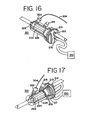
- FIG. 13-17 Another embodiment of a gas humidification apparatus is shown In Figs. 13-17 .
- the gas humidification apparatus 301 essentially has the same structure as the gas humidification apparatus 201 of Figs. 5-12 and so like components will be designated with like numerals.
- One difference is that a second port 302 is added to the housing 226.
- the second port 302 is positioned between the humidification material 224 and the outlet 228 so as to allow a distal end of a catheter 304 to be inserted into the port 302.
- the distal end of the catheter 304 may be positioned within the port 302, within the interior of the gas humidification apparatus 301 or within a tube attached to the outlet 228 and in fluid communication with a section of a patient, or within the section of the patient.
- a catheter that can be inserted into the gas humidification apparatus 201 is the catheter described in U.S. Patent No. 5,964,223 , the entire contents of which are incorporated herein by reference.
- Other devices can be inserted into the port 302 in a similar manner as described above with respect to catheter 304, such as a lumen and an endoscope.
- gases, liquids, aerosols and medicines may be conveyed to a patient by a tube or other know dispensing devices inserted through the port 302 and exiting out of the outlet 228 into the patient.
- the materials dispensed into the port 302 by the above-mentioned dispensing devices may have properties that raise the humidity of the gas within the interior of the gas humidification apparatus 301.
- the gas humidification apparatus 301 may include the temperature sensors, humidity sensors and control circuitry previously described with respect to the embodiments of FIGS. 1-4 and 18 so that the temperature and humidity of the gas flowing within the apparatus and delivered to a patient is controlled.
- the flowing gas achieves a humidity that ranges from approximately 80 to 100 percent humidity and achieves a temperature that ranges from approximately 90 to 105 degrees Fahrenheit at a constant flow rate of approximately 20 liters per minute.
Abstract
Description
- Applicants claim, under 35 U.S.C. § 119(e), the benefit of priority of the filing date of June 30, 2000 of United States Provisional Patent Application Serial No.
60/215,442 - The present invention relates to an apparatus and method used to humidify and/or warm a gas prior to its use in a surgical or other medical procedure.
- Many medical and surgical procedures require the supply to a patient of warmed and/or humidified gas at constant high flow rates. Ideally, the flow rate should be approximately 20 liters per minute, the relative humidity should be approximately 80 to 100 percent, and the temperature approximately 90 to 105 degrees Fahrenheit. Most prior art devices cannot meet or exceed these ideal characteristics. The flow rate of many prior devices is well below 20 liters per minute. Commonly, the flow rate of prior devices has been generally 12 to 14 liters per minute. Most of these devices generally operate by forcing the gas through the humidification material, thereby requiring a high degree of pressure. This increased pressure reduces the flow rate of the gas even further.
- One aspect of the present invention regards a gas humidification apparatus that includes an Inlet, a humidification device in fluid communication with the inlet, the humidification device having a humidification material that readily absorbs moisture and readily releases moisture when exposed to a dry environment, wherein the humidification material has a configuration that generates turbulence in a gas as it passes over a surface of the humidification material and an outlet In fluid communication with the humidification device.
- A second aspect of the present invention regards a gas humidification apparatus that includes an Inlet, a humidification device in fluid communication with the Inlet, the humidification device having a humidification material that readily absorbs moisture and readily releases moisture when exposed to a dry environment, wherein the humidification material is placed within a shell that has a configuration that generates turbulence in a gas as it passes over a surface of the shell and an outlet in fluid communication with the humidification device.
- A third aspect of the present invention regards a gas humidification apparatus that includes an inlet, a humidification device in fluid communication with the inlet, the humidification device having a heater housing that includes a heater and a plurality of openings. A humidification material that readily absorbs moisture and readily releases moisture when exposed to a dry environment and an outlet in fluid communication with the humidification device.
- A fourth aspect of the present invention regards a gas humidification apparatus that includes inlet means for supplying a gas, turbulence means for generating turbulence in the gas and outlet means for expelling the turbulent gas from the gas humidification apparatus.
- A fifth aspect of the present invention regards a method of humidifying a gas that includes supplying a gas to a surface of a humidification material that readily absorbs moisture and readily releases moisture when exposed to a dry environment and generating turbulence in gas as it passes over the surface of the humidification material.
- A sixth aspect of the present invention regards a method of humidifying a gas that includes warming a gas, humidifying the gas and placing a catheter in fluid communication with the gas during the humidifying.
- A seventh aspect of the present invention regards a gas apparatus that Includes an Inlet, a heater In fluid communication with the inlet and a temperature sensor for measuring a temperature of a gas that flows within the gas apparatus in an indirect manner.
- An eighth aspect of the present invention regards a method of humidifying a gas that includes warming a gas, humidifying the gas and flowing the gas over a surface of a humidifier.
- Each of the above aspects provides the advantage of supplying a patient with warmed and/or humidified gas at or near preferred rates, humidity and/or temperature.
- The foregoing and other features and advantages of the invention will become further apparent from the following detailed description of the presently preferred embodiments, read in conjunction with the accompanying drawings.
-
-
Figure 1 shows a first embodiment of a gas warmer and/or humidifier apparatus according to the present invention; -
Figure 2 shows a second embodiment of a gas warmer and/or humidifier apparatus according to the present invention having a plurality of baffles in the shell; -
Figure 3 shows a third embodiment of a gas warmer and/or humidifier apparatus according to the present invention having an external temperature or humidity sensor; -
Figure 4 shows a cross section perspective view of a gas warmer and/or humidifier apparatus; -
Figure 5 shows a perspective exploded view of a fourth embodiment of gas humidification apparatus according to the present invention; -
Figure 6 shows a right top side perspective view of the gas humidification apparatus ofFigure 5 ; -
Figure 7 shows a right bottom side perspective view of the gas humidification apparatus ofFigure 5 ; -
Figure 8 shows a top view of the gas humidification apparatus ofFigure 5 ; -
Figure 9 shows a right side view of the gas humidification apparatus ofFigure 5 ; -
Figure 10 shows a front view of the gas humidification apparatus ofFigure 5 ; -
Figure 11 shows a rear side perspective view of the gas humidification apparatus ofFigure 5 ; -
Figure 12 shows a top view of an embodiment of a humidification material to be used with the gas humidification apparatus ofFigure 5 ; -
Figure 13 shows a perspective view of a fifth embodiment of gas humidification apparatus according to the present Invention; -
Figure 14 shows a side view of the gas humidification apparatus ofFigure 13 ; -
Figure 15 shows a partially exposed side view of the gas humidification apparatus ofFigure 13 ; -
Figure 16 shows a right front side and partially exposed perspective view of the gas humidification apparatus ofFigure 13 ; -
Figure 17 shows a right rear side and partially exposed perspective view of the gas humidification apparatus ofFigure 13 ; and -
Figure 18 shows a circuit diagram of heating circuit that can be used with the gas humidification apparatus/gas warmer and/or heater apparati ofFigures 1-17 . -
Figure 1 shows one embodiment of the gas warmer and humidification apparatus .Figure 1 shows the apparatus used in conjunction with an insufflation device.Figs. 1-3 show theapparatus 1 associated with theinsufflation tubing 10. In a preferred embodiment, the apparatus is located downstream from the gas source for the insufflation device where downstream refers to a location closer to output of theinsufflation tubing 10 or a patient. Theapparatus 1 has an upstream end located nearer to the gas source and a downstream end located closer to the patient. The gas warmer andhumidifier apparatus 1 may be constructed as a re-useable or disposable product. - As shown In
Fig. 1 , In one embodiment, agas Inlet port 12 is located at an upstream end of theapparatus 1 and associable with theinsufflation tubing 10. A plurality ofplugs 14 may also be located at the upstream end of theapparatus 1. Theplugs 14 may be male leads for association with theheater 18 and/or a thermocouple and/or other suitable sensing devices. It is to be understood that the location at the upstream end is variable and other locations consistent with the characteristics of theplugs 14 are envisioned. - As shown in
Figs. 1-3 , the general arrangement of one embodiment of theapparatus 1 follows. Theapparatus 1 includes aheater 18. Surrounding theheater 18 is acore 20. Thecore 20 maintains theheater 18 in a significantly watertight environment. About thecore 20 is ahumidification material 24. Thehumidification material 24 generally envelops theentire core 20. Thehumidification material 24 may only partially envelop thecore 20 as well. Ashell 26, acting as a housing, surroundshumidification material 24. At the downstream end of theapparatus 1 may be agas outlet 28 associable with a downstream portion of theinsufflation tube 10. - The
heater 18 of the above embodiment may include a conventional cartridge heater, a heat generating wire, a light bulb, or other heat generating device capable of creating an elevated temperature that can radiate from the surface of the heater. As shown inFigure 1 , theheater 18 is insertable within acore 20 of non-conductive material. In further embodiments, as shown inFig. 2 , theheater 18 and plugs 14 are molded into a single assembly that is then molded with the core 20 to make a single unit. - The
heater 18 can be a metal structure with integral sensing elements or eternal sensing elements. It can also be molded of a high temperature resistant plastic. Either the metal or theplastic heater 18 is disposable, although the lower cost of theplastic heater 18 may better suit it as adisposable heater 18. Further, the disposability or re-usability of theapparatus 1 aids In maintaining theapparatus 1 sterile for any purposes that may require asterile apparatus 1. - In a preferred embodiment, the
heater 18 has approximately 36 watts of power althoughheaters 18 with other wattage, such as between 10 watts and 50 watts, can also be used. Theheater 18 typically is approximately 1 to 5 inches long, preferably approximately 1½ to 3 inches long, but other sizes can be used depending on the physical size of the other components, and the amount of humidity to be generated. As shown inFIGS. 1-4 and18 , theheater 18 may be connected to controlcircuitry 100 controls the amount of heat and rate of heat generated by theheater 18. As shown inFIG. 18 , thecontrol circuitry 100 includes one ormore temperature sensors 102 and acontrol system 104 to regulate the degree of energy supplied to theheater 18 by modulating the current supplied to the heater via turning on/off the current and raising or lowering the current. In the case of using twotemperature sensors 102, thetemperature sensors 102 each independently measure the temperature of thecore 20. The temperature signals fromtemperature sensors 102 are continuously fed toamplifiers 105. The two signals are compared with each other and if it is determined that the difference between the signals reaches or exceeds a predetermined level, such as 5°C, then thecontrol system 104 turns off thecurrent drivers 106 and the current supplied to theheater 18. Thecurrent drivers 106 are turned off because reaching or exceeding the predetermined level denotes that one or both of thesensors 102 are defective and need to be replaced. - Assuming that the
sensors 102 are not deemed defective, thecontrol system 104 includes four identicalcurrent drivers 106 that are in parallel with one another as shown inFIG. 18 . Eachdriver 106 provides an output that is identical with the outputs of the other threedrivers 106. Thecontrol system 104 will drive each of the outputs of thecurrent drivers 106 with approximately a 25% duty cycle wave shape. The four drivers combined will provide approximately 100% drive to theheater 18. Eachdriver 106 includes acapacitor 108 of 1000 µF in parallel with afuse 110. Thecapacitors 108 direct the current during its respective 25% duty cycle away from itscorresponding fuse 110. In the event that asingle driver 106 fails, allowing continuous current flow, the correspondingcapacitor 108 will charge up and allow current to flow through thecorresponding fuse 110. In less than approximately 2 seconds, thefuse 110 In thedriver circuit 106 will create an open circuit, thus preventing uncontrolled current to flow to theheater 18. - In one embodiment, the
apparatus 1 can have wiring to theheater 18 permanently attached. In another embodiment shown inFig. 1 , theapparatus 1 can have wiring to theheater 18 constructed with an Integral connector that can be molded into theapparatus 1 or connected/disconnected via a one time use tab connection system. In yet another embodiment, theapparatus 1 can have wiring to theheater 18 with the terminations molded into a natural connector, so that the cabling can be plugged into it, reducing its cost. The electronic wiring used to provide power and to measure the temperature or humidity can be wired directly to the active elements and over molded. In the preferred embodiment, the output wires will be molded or inserted into theshell 26 in order to make the cord detachable from theapparatus 1. - The
heater 18 may be controlled by conventional heater controllers as are available on the market, such as those made by Watlow. Controllers typically are designed to work with temperature sensing devices such as thermocouples resistance temperature detectors (RTD's) and or thermistors. - Optionally, in further embodiments, the
apparatus 1 can be provided with additional circuitry to measure humidity using a humidity sensor. Humidity sensors are available through Omega Engineering located in Atlanta, Georgia, which can supply both the sensor and circuitry for reading and display. Additionally, optionally, the temperature of the gas and the humidity of the gas could be displayed with additional circuitry. A remote power unit, part of the insufflator, or part of any other device used in the Operating Room associated with endoscopic procedures could provide the additional circuitry to display this information. Based on the readings, adjustments could be made on the amount of moisture fed to thehumidification material 24, or how much heat should be applied, or both. - In one embodiment, control could also be tied to the Insufflator to supply the circuitry mentioned above. By monitoring characteristics in temperature, gas volume used, gas flow rate and/or humidity readings, the insufflator could dynamically control the variables to maintain optimum conditions.
- The core 20 may be made of, but not limited to, plastic or a sheet metal. Some of the plastics that may be used for the core 20 include polycarbonate, Ryton™, Vesper™, or any of the high temperature plastics. A sheet metal such as aluminum coated with a non-conductive substance may also be used for the
core 20. - As shown in
Figure 1 , theapparatus 1 includes ahumidification material 24. Thehumidification material 24 both readily absorbs moisture and readily releases it when exposed to a dry environment. Materials such as nylon and cotton are just a few of the many commercially available fibers that can meet these requirements. Thehumidification material 24 can have a tubular inside and outside surface. Tubular refers to a smooth surface. Yet, it is envisioned in further embodiments that thehumidification material 24 may have a patterned or varying 15 degrees of a non-smooth surface. - As shown in
Fig. 4 , thehumidification material 24 used in the preferred embodiment has a smooth inner surface and a serrated or star-like shaped outer surface to maximize surface area in the shortest possible linear space.Fig. 4 shows the preferred embodiment including a first and a second section of thehumidification material 24. Each section of thehumidification material 24 is approximately an inch long with an inner channel in intimate contact with theheater 18. Each of these serrated sections is slid over the core 20 that contains theheater 18. Preferably, a ¼ Inch gap should be between the serrated sections. In one embodiment, a plastic spacer may be Inserted between the serrated sections to provide the gap. In a preferred embodiment, the first and second serrated sections should be set out of phase with each other to force turbulence of the gas and increase the surface area of the material as it passes over the sections. Note that the first and second serrated sections can be formed from a single serrated material by cutting the single serrated material so that the two serrated sections are formed. After cutting, the two serrated sections are rotated relative to one another until the desired phase difference between the two sections is achieved. - The flow of CO2 gas over the absorbent material is affected by the shape of the absorbent material and/or the channel within the
shell 26. In one embodiment, theabsorbent humidification material 24 may be cylindrically shaped and surrounded by a coil used to direct the flow of CO2 gas. As the CO2 gas travels through the windings of the coil, warmth and humidity are transferred to the CO2 gas. The external surfaces of the coil rest against the inside of theshell 26 forming a seal that forces the CO2 gas to travel through or within the coil windings. - Other shapes and sizes can be used for the
humidification material 24. Manufacturers of thishumidification material 24 are Pall Medical located In East Hills, New York and Filtrona Richmond Inc. located in Richmond, Virginia. - The encased
heater 18 elevates the temperature of thehumidification material 24 thereby elevating the temperature of the moisture it contains. The elevated temperature of the moisture leads to the creation of a vapor absorbed into the gas as it flows over thehumidification material 24. Preferably, thehumidification material 24 has a configuration that presents a high surface area to the direction of gas flow to allow Increased opportunity for the moisture to evaporate into the gas thereby humidifying the gas. - In a further embodiment, shown for example in
Fig. 2 , turbulence of the gas is created by the interior of theshell 26 covering thehumidification material 24 andheater 18 having a surface area that is of an irregular pattern or texture. This turbulence may be created using a variety of structures. These structures may be located, for example, on or as part of theshell 26 orhumidification material 24. Further example of a structure for creating turbulence may be a spiral barrier. In additional embodiments, other structures may be incorporated, for example, by being either attached to thehumidification material 24 or interior of theshell 26 of theapparatus 1. - The moisture applied to the
humidification material 24 can contain medications or additives that will evaporate and be carried along in the humidified gas to the patient. Levels of medication and/or fluid in the gas can be controlled by timed evaporation and adsorption rates. Fluid could be infused by syringe, gravity feed through tubing, or by any number of pumps, to retain proper saturation levels. - The
apparatus 1 will have aport 16 for the infusion of fluid for the production of moisture. Moisture may include sterile water, medication, or a mixture of fluids required for merely humidification or dispensing of medication. Theport 16 can be of the standard injection port used typically in the medical industry, a valve, or any other device, which can open or close allowing for the entrance of the fluid. - The
apparatus 1 includes one or more temperature sensing devices (not shown) to regulate theheater 18. Each temperature-sensing device can be a resistive temperature device (RTD), a thermister, or a thermocouple. In the preferred embodiment, a K type thermocouple is embedded inside theheater 18 to measure its temperature. Any number of heater controller manufacturers such as Watlow or Hot Watt can provide the temperature sensing and control device. As shown inFigure 1 , theshell 26 is an oblong tube having an internal channel, but any shape that will accommodate the internal elements of the device is acceptable. In the preferred embodiment, the internal channel of theshell 26 will be smooth. In a further embodiment, any form of surface irregularity to promote turbulence without flow restriction is acceptable for the 15 internal channel of theshell 26. Theshell 26 has anoutput opening 28 and aninput opening 12 for the gas. Theshell 26 additionally has afluid fill port 16 for the infusion of fluid. Although, other methods of inserting the appropriate fluid or medicine in theshell 26 are possible. - Overall length of the preferred embodiment will be between 3½ and 4 inches. Preferably, the
apparatus 1 will weigh approximately four ounces. Theshell 26 can be made of any suitable material, for example, metal or plastic. - In additional embodiments, as shown In
Figure 3 , ahumidity sensor 34 may be included In theapparatus 1.Appropriate humidity sensors 34 can be obtained from Omega Corporation located in Atlanta, Georgia. - Optionally, in further embodiments, in addition to the temperature sensing device described above, an external
temperature sensing device 32 can be Inserted in theinsufflation tubing 10 just outside of thegas outlet 28. The same types of temperature sensing devices Internal to theapparatus 1 as described above can be used. Thisdevice 32 measures the downstream temperature of the gas. - The temperature of the gas is related to the temperature of the
heater 18. The temperature sensing device located within theheater 18 measures the temperature of theheater 18. The temperature of the gas is not directly measured. Rather, the resulting temperature of the gas correlates to the temperature of the heater. - The warmed and humidified gas leaves the
apparatus 1 through agas outlet 28. The gas outlet may be a series of holes. The gas then enters theinsufflation tubing 10 for possible delivery to a patient. - Another embodiment of a gas humidification apparatus is shown in
Figs. 5-12 . In a manner similar to the devices ofFigs. 1-4 , thegas humidification apparatus 201 can be used in conjunction with an insufflation device. In particular thegas humidification apparatus 201 is located downstream from a gas source for the insufflation device. Thegas humidification apparatus 201 may be constructed as a re-useable or disposable product. - As shown in
Figs. 5, 6, 9 and 10 , agas inlet port 212 is attached through a side portion of afront cap 213 of thegas humidification apparatus 201. In addition, aninlet port 215 is attached through a central portion of thefront cap 213. Theinlet port 215 allows for electrical components and wiring to be inserted into thegas humidification apparatus 201. Thegas humidification apparatus 201 can be modified so that theports - As shown in
Fig. 5 , thecap 213 includes an annularmetallic heater housing 217 that is attached thereto. Theheater housing 217 is in fluid communication with thegas inlet port 212. Theheater housing 217 contains a heater cartridge that is well known in the art. When activated the heater cartridge heats up the interior and body of theheater housing 217 so that gases within and outside theheater housing 217 are heated. Theheater housing 217 also includes a plurality ofcircular holes 219 having a diameter of approximately 0.1" (0.254cm). Other shapes and sizes for theholes 219 are possible, such as triangular and square shaped openings. When gas flows into thegas humidification apparatus 201 via thegas Inlet port 212, the gas flows into theheater housing 217, where it is heated if necessary, and then flows out of theholes 219. As shown inFig. 5 , there are approximately sixteenholes 219 that are arranged equidistantly from one another along an annular ring. Theholes 219 of theheater housing 217 improve the rate of heating of the gas within thegas humidification apparatus 201 and create turbulence for the gas flowing within thegas humidification apparatus 201. - Two of the
holes 219 preferably have their own RTD sensor. These sensors operate in the same manner as the temperature sensors for the embodiments ofFigs. 1-4 . In particular, the temperature measured by the two sensors are compared with one another to determine if one or both of the sensors is defective. - As shown in
Fig. 5 , a rearcylindrical portion 223 of theheater housing 217 is snugly inserted into a cylindrical central opening of ahumidification material 224 that is preferably made of the same material as thehumidification materials 24 described previously with respect toFigs. 1-4 . Awasher 221 is fitted over therear portion 223 and abuts against the rear face of thehumidification material 224 and acts as a stop in that it prevents thehumidification material 224 from slipping off of therear portion 223 and being wedged into anoutlet 228. - in an alternative embodiment, the
gas humidification apparatus 201 can further include aplate 225 positioned between the front or proximal end of thehumidification material 224 and theheater housing 217. Since theholes 219 face the front end of thehumidification material 224, theplate 225 allows the gas to flow along the exposed side of thehumidification material 224. Note that the gas will flow along the side of thehumidification material 224 with or without the presence of theplate 225. - As shown in
Fig. 12 , thehumidification material 224 has a star-like pattern with ten to twelve points that aid in generating turbulence in the gas within thegas humidification apparatus 201 in a similar manner that thehumidification material 24 ofFigs. 1 and4 do. - In an alternative embodiment, a
second humidification material 224 may be spaced from the first humidification material by a spacer and out of phase with the first humidification material in the same manner as described previously with respect to the embodiment ofFigs. 1 and4 . - As shown in
FIG. 5 , the assembledhumidification material 224 andwasher 221 and theinlet port 215 and theheater housing 217 are inserted into a housing orshell 226. After insertion, thefront cap 213 is screwed on or snap fit onto theheater housing 217. Thehousing 226 is made of a suitable material, such as plastic or metal, and has adownstream outlet 228 that allows the gas to flow outside of thehousing 226. - As shown in
FIGS. 5-9 and 11 , thehousing 226 includes aport 216 that allows fluid to be infused by syringe, gravity feed through tubing, or by any number of pumps, to thehumidification material 224. The fluids infused may include sterile water, medication, or a mixture of fluids required for merely humidification or dispensing of medication. The interior end of theport 216 is positioned so that infused fluids drip into thehousing 226 and are soaked up by theentire humidification material 224 by capillary action. Theport 216 is similar to theport 16 described previously with respect to the embodiments ofFIGS. 1-4 . - As shown in
FIGS. 5-9 , thehousing 226 is inserted into a sleeve orshroud 230 so that theport 216 is slid along a slit 232 formed in thesleeve 230 and theoutlet 228 extends through a rear opening 234 of thesleeve 230. Thesleeve 230 is snap fit to thehousing 226. Thesleeve 230 is made of a thermal insulation material that retains the heat within thehousing 226 so that a person can handle thesleeve 230 without fear of being exposed to excessive heat and without significantly heating up the ambient atmosphere. - Note that the
sleeve 230, thehousing 226 and thehumidification material 224 may be disposable while thecap 213 and its attachedheater housing 217 may be reusable. - The
gas humidification apparatus 201 may include the temperature sensors, humidity sensors and control circuitry previously described with respect to the embodiments ofFIGS. 1-4 and18 so that the temperature and humidity of the gas flowing within the apparatus and delivered to a patient viaoutlet 228 is controlled. - Another embodiment of a gas humidification apparatus is shown In
Figs. 13-17 . Thegas humidification apparatus 301 essentially has the same structure as thegas humidification apparatus 201 ofFigs. 5-12 and so like components will be designated with like numerals. One difference is that asecond port 302 is added to thehousing 226. Thesecond port 302 is positioned between thehumidification material 224 and theoutlet 228 so as to allow a distal end of acatheter 304 to be inserted into theport 302. Depending on the intended material to be delivered to the patient, the distal end of thecatheter 304 may be positioned within theport 302, within the interior of thegas humidification apparatus 301 or within a tube attached to theoutlet 228 and in fluid communication with a section of a patient, or within the section of the patient. An example of a catheter that can be inserted into thegas humidification apparatus 201 is the catheter described inU.S. Patent No. 5,964,223 , the entire contents of which are incorporated herein by reference. Other devices can be inserted into theport 302 in a similar manner as described above with respect tocatheter 304, such as a lumen and an endoscope. Furthermore, gases, liquids, aerosols and medicines may be conveyed to a patient by a tube or other know dispensing devices inserted through theport 302 and exiting out of theoutlet 228 into the patient. Note that the materials dispensed into theport 302 by the above-mentioned dispensing devices may have properties that raise the humidity of the gas within the interior of thegas humidification apparatus 301. - The
gas humidification apparatus 301 may include the temperature sensors, humidity sensors and control circuitry previously described with respect to the embodiments ofFIGS. 1-4 and18 so that the temperature and humidity of the gas flowing within the apparatus and delivered to a patient is controlled. - In each of the devices for humidifying and/or warming a gas described previously with respect to
FIGS. 1-18 , it is desired that the flowing gas achieves a humidity that ranges from approximately 80 to 100 percent humidity and achieves a temperature that ranges from approximately 90 to 105 degrees Fahrenheit at a constant flow rate of approximately 20 liters per minute. - The embodiments of the invention disclosed herein are presently considered to be preferred, various changes and modifications can be made without departing from the spirit and scope of the invention. As noted, the discussion above is descriptive, illustrative and exemplary and is not to be taken as limiting the scope defined by any appended claims, and all changes that come within the meaning and range of equivalents are intended to be embraced therein.
- Further embodiments of the present invention are as follows.
- 1. A gas humidification apparatus comprising:
- an inlet;
- a humidification device in fluid communication with said inlet, said humidification device comprising:
- a humidification material that readily absorbs moisture and readily releases moisture when exposed to a dry environment, wherein said humidification material has a configuration that generates turbulence in a gas as it passes over a surface of said humidification material;
- an outlet in fluid communication with said humidification device.
- 2. The gas
humidification apparatus embodiment 1, wherein said surface of said humidification material is patterned. - 3. The gas humidification apparatus of embodiment 2, wherein said surface of said humidification material is serrated.
- 4. The gas humidification apparatus of embodiment 2, wherein said surface of said humidification material is star-shaped.
- 5. The gas humidification apparatus of embodiment 2, wherein said surface of said humidification material varies 15 degrees of a non-smooth surface.
- 6. The gas humidification apparatus of embodiment 2, wherein said surface of said humidification material is irregularly patterned.
- 7. The gas
humidification apparatus embodiment 1, wherein said surface of said humidification material is maximized in surface area in the shortest possible linear space. - 8. The gas humidification apparatus of
embodiment 1, wherein said humidification device further comprises a second humidification material that is spaced from said humidification material and readily absorbs moisture and readily releases moisture when exposed to a dry environment, wherein said second humidification material has a configuration that generates turbulence for a gas that should pass over a surface of said second humidification surface. - 9. The gas humidification apparatus of
embodiment 8, further comprising a spacer interposed between said humidification material and said second humidification material. - 10. The gas humidification apparatus of
embodiment 8, wherein said surface of said second humidification material is patterned. - 11. The gas humidification apparatus of
embodiment 10, wherein said surface of said second humidification material is out of phase with respect to said surface of said humidification material. - 12. The gas
humidification apparatus embodiment 1, wherein said humidification material comprises a medication infused therein. - 13. The gas humidification apparatus of
embodiment 1, further comprising a heater. - 14. The gas humidification apparatus of embodiment 13, wherein said heater is positioned separate from said humidification device.
- 15. The gas humidification apparatus of
embodiment 14, wherein said heater is positioned upstream from said humidification device. - 16. The gas humidification apparatus of embodiment 13, wherein said humidification device envelops said heater.
- 17. The gas humidification apparatus of embodiment 13, further comprising a core into which said heater is inserted.
- 18. The gas humidification apparatus of embodiment 17, wherein said core comprises a non-conductive material.
- 19. The gas humidification apparatus of
embodiment 1, further comprising a humidity sensor for measuring humidity of a gas that flows within said gas humidification apparatus. - 20. The gas humidification apparatus of
embodiment 1, further comprising a temperature sensor for measuring a temperature of a gas that flows within said gas humidification apparatus. - 21. The gas humidification apparatus of embodiment 19, further comprising a temperature sensor for measuring a temperature of said gas that flows within said gas humidification apparatus.
- 22. The gas humidification apparatus of
embodiment 20, wherein said temperature sensor measures said temperature of said gas in an indirect manner. - 23. The gas humidification apparatus of embodiment 13, further comprising a temperature sensor for measuring a temperature of a gas that flows within said gas humidification apparatus.
- 24. The gas humidification apparatus of embodiment 23, wherein said temperature sensor measures said temperature of said gas in an indirect manner by measuring a temperature of said heater.
- 25. The gas humidification apparatus embodiment 19, further comprising a control device connected to said humidity sensor that controls humidity within said gas humidification apparatus based on a signal from said humidity sensor.
- 26. The gas humidification apparatus of
embodiment 20, further comprising a control device connected to said temperature sensor that controls temperature within said gas humidification apparatus based on a signal from said temperature sensor. - 27. The gas humidification apparatus of embodiment 21, further comprising a control device connected to said humidity sensor and said temperature sensor that controls humidity and temperature within said gas humidification apparatus based on signals from said humidity sensor and said temperature sensor.
- 28. The gas humidification apparatus of
embodiment 1, further comprising:- a port in fluid communication with said gas humidification apparatus; and
- a catheter inserted into said port.
- 29. A gas humidification apparatus comprising:
- an inlet;
- a humidification device in fluid communication with said Inlet, said humidification device comprising:
- a humidification material that readily absorbs moisture and readily releases moisture when exposed to a dry environment, wherein said humidification material is placed within a shell that has a configuration that generates turbulence in a gas as it passes over a surface of said shell;
- an outlet In fluid communication with said humidification device.
- 30. The gas humidification apparatus of embodiment 29, further comprising a coil positioned adjacent to said shell that forces a gas to travel through or within said coil.
- 31. The gas humidification apparatus of embodiment 29, wherein said shell comprises an interior surface with an irregular pattern.
- 32. The gas humidification apparatus of embodiment 29, wherein said shell comprises an interior surface with a spiral barrier.
- 33. The gas humidification apparatus of embodiment 29, wherein said humidification material is cylindrical in shape.
- 34. The gas humidification apparatus of embodiment 29, wherein said humidification material comprises a medication infused therein.
- 35. The gas humidification apparatus of embodiment 29, further comprising a heater.
- 36. A gas humidification apparatus comprising:
- an Inlet;
- a humidification device in fluid communication with said inlet, said humidification device comprising:
- a heater housing comprising a heater and a plurality of openings;
- a humidification material that readily absorbs moisture and readily releases moisture when exposed to a dry environment;
- an outlet in fluid communication with said humidification device.
- 37. The gas humidification apparatus of
embodiment 36, wherein said plurality of openings have a configuration that generates turbulence in a gas as it passes through said plurality of openings. - 38. The gas humidification apparatus of
embodiment 36, wherein said surface of said humidification material is patterned. - 39. The gas humidification apparatus of embodiment 38, wherein said surface of said humidification material is serrated.
- 40. The gas humidification apparatus of embodiment 38, wherein said surface of said humidification material is star-shaped.
- 41. The gas humidification apparatus of
embodiment 36, wherein said humidification device further comprises a second humidification material that is spaced from said humidification material and readily absorbs moisture and readily releases moisture when exposed to a dry environment, wherein said second humidification material has a configuration that generates turbulence for a gas that should pass over a surface of said second humidification surface. - 42. The gas humidification apparatus embodiment 41, further comprising a spacer interposed between said humidification material and said second humidification material.
- 43. The gas humidification apparatus of embodiment 41, wherein said surface of said second humidification material is patterned.
- 44. The gas humidification apparatus of embodiment 43, wherein said surface of said second humidification material is out of phase with respect to said surface of said humidification material.
- 45. The gas humidification apparatus of
embodiment 36, wherein said humidification material comprises a medication infused therein. - 46. The gas humidification apparatus of
embodiment 36, further comprising a humidity sensor for measuring humidity of a gas that flows within said gas humidification apparatus. - 47. The gas
humidification apparatus embodiment 36, further comprising a temperature sensor for measuring a temperature of a gas that flows within said gas humidification apparatus. - 48. The gas humidification apparatus of embodiment 46, further comprising a temperature sensor for measuring a temperature of said gas that flows within said gas humidification apparatus.
- 49. The gas humidification apparatus of embodiment 47, wherein said temperature sensor measures said temperature of said gas in an indirect manner.
- 50. The gas humidification apparatus of embodiment 46, further comprising a control device connected to said humidity sensor that controls humidity within said gas humidification apparatus based on a signal from said humidity sensor.
- 51. The gas humidification apparatus of embodiment 47, further comprising a control device connected to said temperature sensor that controls temperature within said gas humidification apparatus based on a signal from said temperature sensor.
- 52. The gas humidification apparatus of embodiment 48, further comprising a control device connected to said humidity sensor and said temperature sensor that controls humidity and temperature within said gas humidification apparatus based on signals from said humidity sensor and said temperature sensor.
- 53. The gas humidification apparatus of
embodiment 36, further comprising:- a port in fluid communication with said gas humidification apparatus; and
- a catheter inserted into said port.
- 54. A gas humidification apparatus comprising:
- inlet means for supplying a gas;
- turbulence means for generating turbulence in said gas;
and - outlet means for expelling said turbulent gas from said gas humidification apparatus.
- 55. The gas humidification apparatus of embodiment 54, wherein said turbulence means comprises a humidification material that readily absorbs moisture and readily releases moisture when exposed to a dry environment.
- 56. The gas humidification apparatus of embodiment 54, further comprising means for heating said gas.
- 57. The gas humidification apparatus of embodiment 54, further comprising:
- a port in fluid communication with said gas humidification apparatus; and
- a catheter inserted into said port.
- 58. A method of humidifying a gas comprising:
- supplying a gas to a surface of a humidification material that readily absorbs moisture and readily releases moisture when exposed to a dry environment; and
- generating turbulence in said gas as it passes over said surface of said humidification material.
- 59. The method of embodiment 58, further comprising supplying said turbulent gas to a patient.
- 60. The method of embodiment 58, further comprising measuring humidity of said gas.
- 61. The method of embodiment 58, further comprising measuring a temperature of said gas.
- 62. The method of embodiment 60, further comprising measuring a temperature of said gas.
- 63. The method of embodiment 61, wherein said measuring said temperature of said gas is done in an indirect manner.
- 64. The method of embodiment 60, further comprising controlling said humidity of said gas based on said measured humidity.
- 65. The method of embodiment 61, further comprising controlling said temperature of said gas based on said measured temperature.
- 66. The method of embodiment 62, further comprising:
- controlling said humidity of said gas based on said measured humidity; and
- controlling said temperature of said gas based on said measured temperature.
- 67. A method of humidifying a gas comprising:
- warming a gas;
- humidifying said gas; and
- placing a catheter in fluid communication with said gas during said humidifying.
- 68. The method of embodiment 67, further comprising generating turbulence in said gas during said humidifying.
- 69. The method of embodiment 67, further comprising supplying said gas to a patient.
- 70. A gas apparatus comprising:
- an inlet;
- a heater in fluid communication with said inlet,
- a temperature sensor for measuring a temperature of a gas that flows within said gas apparatus in an indirect manner.
- 71. The gas apparatus of embodiment 70, wherein said temperature sensor measures said temperature of said gas in an indirect manner by measuring a temperature of said heater.
- 72. The gas apparatus of embodiment 70, further comprising a humidification material that readily absorbs moisture and readily releases moisture when exposed to a dry environment.
- 73. The gas apparatus of embodiment 72, wherein said humidification material has a configuration that generates turbulence for a gas that should pass over a surface of said humidification material.
- 74. A method of humidifying a gas comprising:
- warming a gas;
- humidifying said gas; and
- flowing said gas over a surface of a humidifier.
- 75. The method of embodiment 74, further comprising generating turbulence in said gas during said humidifying.
- 76. The method of embodiment 74, further comprising generating turbulence in said gas during said flowing.
- 77. The method of embodiment 74, further comprising supplying said gas to a patient.
Claims (11)
- A gas humidification apparatus for use in a medical procedure comprising:a gas inlet;a humidification device in fluid communication with said inlet, said humidification device comprising:a heater for warming a gas flowing through the chamber;a humidification material adjacent to said heater that readily absorbs moisture and readily releases moisture when exposed to a dry environment;a gas outlet in fluid communication with said humidification device;an insufflator comprising a gas source and connected to said humidification device receiving said gas from said insufflator which receives said gas from said gas source; andsaid insufflator having a control controlling said heater and monitoring temperature, gas volume, gas flow rate and/or humidity.
- The apparatus of claim 1, wherein said humidification device comprises a plurality of gas flow channels for flowing gas over said humidification material.
- The apparatus of claim 1, wherein said heater comprises a heater housing in fluid communication with said gas inlet.
- The apparatus of claim 3, wherein said heater housing comprises a plurality of holes.
- The apparatus of claim 1, wherein said humidification material comprises a cylindrical central opening.
- The apparatus of claim 1, wherein said heater comprises a cylindrical portion for insertion into the cylindrical central opening.
- The apparatus of claim 2, wherein said humidification material comprises 10 or 12 gas flow channels.
- The apparatus of claim 4, wherein the plurality of holes directs the gas to flow into the plurality of gas flow channels.
- The apparatus of claim 1, wherein said humidification device comprises a port added to the housing.
- The apparatus of claim 9, wherein the port is adapted for a dispending device to be inserted within said port for delivering a medicament in aerosol form to humidified gas as it exits said gas outlet.
- The apparatus of claim 1, said gas source is a source of carbon dioxide.
Applications Claiming Priority (3)
| Application Number | Priority Date | Filing Date | Title |
|---|---|---|---|
| US21544200P | 2000-06-30 | 2000-06-30 | |
| EP01947705.8A EP1294428B1 (en) | 2000-06-30 | 2001-06-29 | Apparatus for humidification and warming of air |
| PCT/IB2001/001162 WO2002000284A2 (en) | 2000-06-30 | 2001-06-29 | Method and apparatus for humidification and warming of air |
Related Parent Applications (3)
| Application Number | Title | Priority Date | Filing Date |
|---|---|---|---|
| EP01947705.8A Division EP1294428B1 (en) | 2000-06-30 | 2001-06-29 | Apparatus for humidification and warming of air |
| EP01947705.8A Division-Into EP1294428B1 (en) | 2000-06-30 | 2001-06-29 | Apparatus for humidification and warming of air |
| EP01947705.8 Division | 2001-06-29 |
Publications (3)
| Publication Number | Publication Date |
|---|---|
| EP2295106A2 true EP2295106A2 (en) | 2011-03-16 |
| EP2295106A3 EP2295106A3 (en) | 2015-10-28 |
| EP2295106B1 EP2295106B1 (en) | 2020-08-05 |
Family
ID=22802997
Family Applications (2)
| Application Number | Title | Priority Date | Filing Date |
|---|---|---|---|
| EP10012593.9A Expired - Lifetime EP2295106B1 (en) | 2000-06-30 | 2001-06-29 | Apparatus for humidification and warming of air |
| EP01947705.8A Expired - Lifetime EP1294428B1 (en) | 2000-06-30 | 2001-06-29 | Apparatus for humidification and warming of air |
Family Applications After (1)
| Application Number | Title | Priority Date | Filing Date |
|---|---|---|---|
| EP01947705.8A Expired - Lifetime EP1294428B1 (en) | 2000-06-30 | 2001-06-29 | Apparatus for humidification and warming of air |
Country Status (5)
| Country | Link |
|---|---|
| EP (2) | EP2295106B1 (en) |
| JP (1) | JP5254516B2 (en) |
| AU (1) | AU2001269349A1 (en) |
| CA (4) | CA2810047C (en) |
| WO (1) | WO2002000284A2 (en) |
Families Citing this family (5)
| Publication number | Priority date | Publication date | Assignee | Title |
|---|---|---|---|---|
| US7811253B2 (en) * | 2004-12-09 | 2010-10-12 | Applied Medical Resources Corporation | Insufflation gas warmer and humidifier |
| US10874821B2 (en) | 2014-12-03 | 2020-12-29 | Fisher & Paykel Healthcare Limited | Respiratory gas therapy |
| DE102015103894A1 (en) | 2015-03-17 | 2016-09-22 | Fritz Stephan Gmbh Medizintechnik | Respirators and control methods for ventilators |
| CN112665065B (en) * | 2020-12-28 | 2022-04-05 | 珠海格力电器股份有限公司 | Humidifier |
| WO2022251898A1 (en) * | 2021-06-04 | 2022-12-08 | Quangang Yang | A device for respiratory support |
Citations (1)
| Publication number | Priority date | Publication date | Assignee | Title |
|---|---|---|---|---|
| US5964223A (en) | 1994-06-17 | 1999-10-12 | Trudell Medical Limited | Nebulizing catheter system and methods of use and manufacture |
Family Cites Families (23)
| Publication number | Priority date | Publication date | Assignee | Title |
|---|---|---|---|---|
| US3659604A (en) * | 1970-03-30 | 1972-05-02 | Fisher & Paykel | Humidifying means |
| US4054622A (en) * | 1970-11-03 | 1977-10-18 | Lester Victor E | Combination nebulizer and humidifier |
| US3954920A (en) * | 1973-09-04 | 1976-05-04 | Parkland International Inc. | Gas humidification system |
| CH581474A5 (en) * | 1974-06-27 | 1976-11-15 | Draegerwerk Ag | |
| US4110419A (en) * | 1975-04-18 | 1978-08-29 | Respiratory Care, Inc. | High-volume disposable and semi-disposable cartridge humidifier with self-contained cartridge sterilizing means, and related method |
| DE2810325A1 (en) * | 1978-03-10 | 1979-09-20 | Hirtz & Co | Medical face mask for hot air - has liq. reservoir and hygrometer at nosepiece for humidity control, and has stop valve |
| US4225542A (en) * | 1978-12-12 | 1980-09-30 | Minnesota Mining And Manufacturing Company | Evaporative humidifier |
| US4657713A (en) * | 1983-05-19 | 1987-04-14 | Intertech Resources Inc. | Heated respiratory therapy humidifier |
| GB2173108B (en) * | 1985-04-04 | 1988-10-05 | Boc Group Plc | Improvements in inhalation apparatus |
| GB2173107B (en) * | 1985-04-04 | 1988-06-15 | Boc Group Plc | Improvements in inhalation apparatus |
| US4921642A (en) * | 1987-12-03 | 1990-05-01 | Puritan-Bennett Corporation | Humidifier module for use in a gas humidification assembly |
| NZ226784A (en) * | 1988-09-29 | 1992-10-28 | Fisher & Paykel | Gas humidifier with microporous wall |
| JPH02118555U (en) * | 1989-03-14 | 1990-09-25 | ||
| NZ238544A (en) * | 1990-06-18 | 1994-10-26 | Ponnet Gilman En Anthony | Respirator with hygroscopic material adjacent outlet to patient |
| US5179966A (en) * | 1990-11-19 | 1993-01-19 | Philip Morris Incorporated | Flavor generating article |
| US5195515A (en) * | 1991-03-06 | 1993-03-23 | Walter Levine | Heated cartridge humidifier and humidification chamber for use therewith |
| AU3713193A (en) * | 1992-04-24 | 1993-10-28 | Fisher & Paykel Limited | Humidifier apparatus and/or gases distribution chambers and/or temperature probes for the same |
| IT1255355B (en) * | 1992-07-22 | 1995-10-31 | Lucio Gibertoni | HYGROSCOPIC CARTRIDGE PARTICULARLY FOR FILTERS FOR USE IN THE MEDICAL-SURGICAL AREA |
| US6068609A (en) * | 1998-05-19 | 2000-05-30 | Douglas E. Ott | Method and apparatus for conditioning gas for medical procedures having humidity monitoring and recharge alert |
| GB9812309D0 (en) * | 1998-06-09 | 1998-08-05 | Smiths Industries Plc | Fluid-treatment devices |
| GB2338420A (en) * | 1998-06-19 | 1999-12-22 | Fisher & Paykel | Humidified sleep apnea treatment apparatus |
| JP3574746B2 (en) * | 1998-06-23 | 2004-10-06 | 大陽東洋酸素株式会社 | Humidifier tube |
| SE9804148D0 (en) * | 1998-12-01 | 1998-12-01 | Siemens Elema Ab | System and method for determining changes in body resources during aided breathing |
-
2001
- 2001-06-29 CA CA2810047A patent/CA2810047C/en not_active Expired - Lifetime
- 2001-06-29 CA CA2408984A patent/CA2408984C/en not_active Expired - Lifetime
- 2001-06-29 JP JP2002505064A patent/JP5254516B2/en not_active Expired - Lifetime
- 2001-06-29 EP EP10012593.9A patent/EP2295106B1/en not_active Expired - Lifetime
- 2001-06-29 EP EP01947705.8A patent/EP1294428B1/en not_active Expired - Lifetime
- 2001-06-29 CA CA2743952A patent/CA2743952C/en not_active Expired - Lifetime
- 2001-06-29 AU AU2001269349A patent/AU2001269349A1/en not_active Abandoned
- 2001-06-29 CA CA2926578A patent/CA2926578A1/en not_active Abandoned
- 2001-06-29 WO PCT/IB2001/001162 patent/WO2002000284A2/en active Application Filing
Patent Citations (1)
| Publication number | Priority date | Publication date | Assignee | Title |
|---|---|---|---|---|
| US5964223A (en) | 1994-06-17 | 1999-10-12 | Trudell Medical Limited | Nebulizing catheter system and methods of use and manufacture |
Also Published As
| Publication number | Publication date |
|---|---|
| CA2743952A1 (en) | 2002-01-03 |
| CA2926578A1 (en) | 2002-01-03 |
| EP2295106B1 (en) | 2020-08-05 |
| JP5254516B2 (en) | 2013-08-07 |
| EP2295106A3 (en) | 2015-10-28 |
| EP1294428A2 (en) | 2003-03-26 |
| EP1294428B1 (en) | 2017-05-10 |
| CA2810047A1 (en) | 2002-01-03 |
| AU2001269349A1 (en) | 2002-01-08 |
| CA2810047C (en) | 2016-05-17 |
| WO2002000284A3 (en) | 2002-06-20 |
| WO2002000284A2 (en) | 2002-01-03 |
| CA2408984C (en) | 2011-08-16 |
| CA2408984A1 (en) | 2002-01-03 |
| CA2743952C (en) | 2013-04-30 |
| JP2005532080A (en) | 2005-10-27 |
Similar Documents
| Publication | Publication Date | Title |
|---|---|---|
| US10052444B2 (en) | Method and apparatus for humidification and warming of air | |
| US5254094A (en) | Physiological fluid warmer | |
| US7455653B2 (en) | Method and apparatus for treating gas for use in endoscopic surgery | |
| JP7118965B2 (en) | filter assembly | |
| AU780294B2 (en) | Method and apparatus for treating gas for delivery to an animal | |
| CA2408984C (en) | Method and apparatus for humidification and warming of air | |
| JP2005532080A6 (en) | Method and apparatus for humidifying and warming air | |
| JP5540064B2 (en) | Method and apparatus for humidifying and warming air | |
| JP7464659B2 (en) | Filter Assembly |
Legal Events
| Date | Code | Title | Description |
|---|---|---|---|
| PUAI | Public reference made under article 153(3) epc to a published international application that has entered the european phase |
Free format text: ORIGINAL CODE: 0009012 |
|
| AC | Divisional application: reference to earlier application |
Ref document number: 1294428 Country of ref document: EP Kind code of ref document: P |
|
| AK | Designated contracting states |
Kind code of ref document: A2 Designated state(s): DE FR GB IT |
|
| PUAL | Search report despatched |
Free format text: ORIGINAL CODE: 0009013 |
|
| AK | Designated contracting states |
Kind code of ref document: A3 Designated state(s): DE FR GB IT |
|
| RIC1 | Information provided on ipc code assigned before grant |
Ipc: A61M 16/16 20060101AFI20150918BHEP Ipc: A61M 16/10 20060101ALI20150918BHEP Ipc: A61M 13/00 20060101ALI20150918BHEP |
|
| 17P | Request for examination filed |
Effective date: 20160405 |
|
| RBV | Designated contracting states (corrected) |
Designated state(s): DE FR GB IT |
|
| STAA | Information on the status of an ep patent application or granted ep patent |
Free format text: STATUS: EXAMINATION IS IN PROGRESS |
|
| 17Q | First examination report despatched |
Effective date: 20170413 |
|
| RAP1 | Party data changed (applicant data changed or rights of an application transferred) |
Owner name: NORTHGATE TECHNOLOGIES INC. |
|
| GRAP | Despatch of communication of intention to grant a patent |
Free format text: ORIGINAL CODE: EPIDOSNIGR1 |
|
| STAA | Information on the status of an ep patent application or granted ep patent |
Free format text: STATUS: GRANT OF PATENT IS INTENDED |
|
| INTG | Intention to grant announced |
Effective date: 20200327 |
|
| GRAS | Grant fee paid |
Free format text: ORIGINAL CODE: EPIDOSNIGR3 |
|
| GRAA | (expected) grant |
Free format text: ORIGINAL CODE: 0009210 |
|
| STAA | Information on the status of an ep patent application or granted ep patent |
Free format text: STATUS: THE PATENT HAS BEEN GRANTED |
|
| AC | Divisional application: reference to earlier application |
Ref document number: 1294428 Country of ref document: EP Kind code of ref document: P |
|
| AK | Designated contracting states |
Kind code of ref document: B1 Designated state(s): DE FR GB IT |
|
| REG | Reference to a national code |
Ref country code: GB Ref legal event code: FG4D |
|
| REG | Reference to a national code |
Ref country code: DE Ref legal event code: R096 Ref document number: 60151293 Country of ref document: DE |
|
| REG | Reference to a national code |
Ref country code: DE Ref legal event code: R097 Ref document number: 60151293 Country of ref document: DE |
|
| PLBE | No opposition filed within time limit |
Free format text: ORIGINAL CODE: 0009261 |
|
| STAA | Information on the status of an ep patent application or granted ep patent |
Free format text: STATUS: NO OPPOSITION FILED WITHIN TIME LIMIT |
|
| REG | Reference to a national code |
Ref country code: DE Ref legal event code: R071 Ref document number: 60151293 Country of ref document: DE |
|
| 26N | No opposition filed |
Effective date: 20210507 |
|
| PG25 | Lapsed in a contracting state [announced via postgrant information from national office to epo] |
Ref country code: IT Free format text: LAPSE BECAUSE OF FAILURE TO SUBMIT A TRANSLATION OF THE DESCRIPTION OR TO PAY THE FEE WITHIN THE PRESCRIBED TIME-LIMIT Effective date: 20200805 |
|
| REG | Reference to a national code |
Ref country code: GB Ref legal event code: PE20 Expiry date: 20210628 |
|
| PG25 | Lapsed in a contracting state [announced via postgrant information from national office to epo] |
Ref country code: GB Free format text: LAPSE BECAUSE OF EXPIRATION OF PROTECTION Effective date: 20210628 |