EP2294436B1 - Method for decreasing bio-effects of magnetic field gradients - Google Patents
Method for decreasing bio-effects of magnetic field gradients Download PDFInfo
- Publication number
- EP2294436B1 EP2294436B1 EP09767831.2A EP09767831A EP2294436B1 EP 2294436 B1 EP2294436 B1 EP 2294436B1 EP 09767831 A EP09767831 A EP 09767831A EP 2294436 B1 EP2294436 B1 EP 2294436B1
- Authority
- EP
- European Patent Office
- Prior art keywords
- magnetic field
- coil
- power source
- pulse
- field gradient
- Prior art date
- Legal status (The legal status is an assumption and is not a legal conclusion. Google has not performed a legal analysis and makes no representation as to the accuracy of the status listed.)
- Active
Links
Images



Classifications
-
- G—PHYSICS
- G01—MEASURING; TESTING
- G01R—MEASURING ELECTRIC VARIABLES; MEASURING MAGNETIC VARIABLES
- G01R33/00—Arrangements or instruments for measuring magnetic variables
- G01R33/20—Arrangements or instruments for measuring magnetic variables involving magnetic resonance
- G01R33/28—Details of apparatus provided for in groups G01R33/44 - G01R33/64
- G01R33/38—Systems for generation, homogenisation or stabilisation of the main or gradient magnetic field
- G01R33/385—Systems for generation, homogenisation or stabilisation of the main or gradient magnetic field using gradient magnetic field coils
- G01R33/3852—Gradient amplifiers; means for controlling the application of a gradient magnetic field to the sample, e.g. a gradient signal synthesizer
-
- G—PHYSICS
- G01—MEASURING; TESTING
- G01R—MEASURING ELECTRIC VARIABLES; MEASURING MAGNETIC VARIABLES
- G01R33/00—Arrangements or instruments for measuring magnetic variables
- G01R33/20—Arrangements or instruments for measuring magnetic variables involving magnetic resonance
- G01R33/28—Details of apparatus provided for in groups G01R33/44 - G01R33/64
- G01R33/288—Provisions within MR facilities for enhancing safety during MR, e.g. reduction of the specific absorption rate [SAR], detection of ferromagnetic objects in the scanner room
Definitions
- the present invention concerns a method for decreasing the bioeffects of magnetic field gradients on tissue(s). More specifically, the present invention concerns a method to decrease bio-effects on neurological tissue from magnetic field gradients, such as those experienced during Magnetic Resonance Imaging ("MRI").
- MRI Magnetic Resonance Imaging
- MRI is a technology whereby a magnetic field gradient is applied to subatomic particles in tissue to spatially encode a subsequent response from the atoms and molecules in the tissue to a radiofrequency pulse. After detection of an electromagnetic response from the tissue, an image of the tissue is generated partly based on that response.
- CONRADI MS ET AL "GENERATION OF SHORT, INTENSE GRADIENT PULSES", JOURNAL OF MAGNETIC RESONANCE, ACADEMIC PRESS, ORLANDO, FL, US, vol. 94, no. 2, 1 September 1991 (1991-09-01), pages 370-375, ISSN: 1090-7807 refers to experiments with gradient pulses of approximately 3 ⁇ s long with peak amplitudes of up to 0.2 T /m. While P.T. et al., Phys.Med.Biol. 49 (2004), 2779-2798 refers to studies investigating rise times considerably longer than 100 ⁇ s where reduction of the rise time does increase magnetic stimulation. Results from a model are reported suggesting that there is a finite limit to electric field strength of about 10.4 V/m as rise time approaches zero.
- magnetic field gradients e.g., switching gradients
- nerves and other electrically-sensitive tissues may elicit undesirable responses in a living organism by induction of electrical pulses in nerves and other electrically-sensitive tissues.
- the model elaborated by Reilly invokes the telegraph equation first applied in the late 1800's to design trans-Atlantic cables.
- RC resistance/capacitance
- the slew rate refers to the rate of change in the magnitude of the gradient, which is typically measured in Teslas per meter per second (T/m/s).
- the prior art also includes evidence of interest in the strength-duration curve from another direction, as manufacturers of neuron-stimulators try to shape the pulse in order to increase stimulation. (See P.J. Maccabee, "Influence of pulse sequence, polarity and amplitude on magnetic stimulation of human and porcine peripheral nerve,” J. Physiol., 513:571-585, 1998 ).
- saving time improves safety for unstable patients. Saving time also may reduce the cost of the MRI sequence.
- a second incentive for increasing slew rate is to increase gradient field strength, which improves spatial resolution.
- the faster one can ramp up the magnetic field per pulse the higher the gradient strength will be for the same overall scan time. Since the gradient strength is proportional to the spatial resolution of the MRI image obtained, a higher slew rate will result in a better spatial resolution. Increased spatial resolution may improve medical diagnosis in some cases.
- switches are used to trigger the generation of a magnetic field gradient.
- the types of switches traditionally used include Insulated-Gate Bipolar Transistor (“IGBT”) and Metal Oxide Semiconductor Field Effect Transistor (“MOSFET”)-based devices.
- IGBT Insulated-Gate Bipolar Transistor
- MOSFET Metal Oxide Semiconductor Field Effect Transistor
- Those high-power solid-state switches are capable of triggering pulses of tenthousand amps in one microsecond, orders of magnitude higher than the IGBT and MOSFET-based systems currently employed in commercial gradient field generators for MRI systems (See D.A. Seeber, J.H. Hoftiezer, and C.H. Pennington, "Pulsed current gradient power supply for microcoil magnetic resonance imaging,” in Magnetic Resonance Engineering, 15(3): 189-200, 2002 ).
- PFLs pulse-forming lines
- PFLs which are also known as Blumlein lines (named for the World-War II-era inventor David Blumlein), are dielectric-filled transmission lines that begin draining their charge when triggered by a solid-state switch. The transmission lines stop delivering current once the dielectric has been drained of charge. Blumlein lines can switch in nanoseconds, and maintain currents for milliseconds. ( K Gasthaus, "A millisecond Blumlein line for the power supply of a high power laser," in J. Phys. E: Instrum., 20:192-195, 1987 ). In order to deliver pulses of varying widths, sets of PFLs may be triggered independently of one another into a common load.
- An additional aspect of the present invention involves the application of magnetic field gradients with a magnitude greater than that traditionally employed.
- the gradient may be up to five (5) times greater than previously applied.
- the magnitude may be greater.
- the current invention takes advantage of a physiological loophole: according to accepted physiological models for ionic channel transport, bi-phasic pulses on the order of a microsecond are too fast for the nerve to change its polarization state, and are, therefore, effectively ignored.
- the present invention capitalizes on this physiological loophole.
- this loophole implies that gradient field thresholds may be increased by factors of five or more above the usual hyperbolic model without triggering any bio-effects.
- the present invention also takes advantage of magnetic pulse delivery systems that are more powerful than traditional systems used to deliver MRI pulses.
- the present invention utilizes solid-state switch and/or PFL technologies that conform to the requirements of MRI gradient amplifiers. These requirements include increased repetition rates, impedance and trigger matching to MRI pulse programming consoles, and electrical/acoustic noise shielding considerations. Downstream modifications include the buttressing of gradient coils to handle the higher electromagnetic (i.e., J x B) forces that will occur at higher current loads, especially in high resolution MRI systems with high static magnetic fields.
- eddy current shielding is likely to be less of a problem than at current regimes, and reductions in inductance are predicted.
- the influence of eddy currents may further be minimized by acquiring signals at long echo time ("TE"), when eddy currents have died down, as contemplated by still another embodiment of the present invention.
- TE long echo time
- the bore of the cryostat may be made significantly larger than the gradient coil, further reducing the influence of eddy currents.
- an MRI device includes a magnetic field generator, typically a magnetic coil and a radio frequency (“RF") generator or transmitter.
- the magnetic coil generates a time-varying magnetic field and the RF generator emits radio waves.
- the MRI device typically also applies a static magnetic field.
- tissue is primarily composed of water molecules, each of which contains hydrogen atoms.
- the hydrogen atoms align with the direction of the magnetic field.
- the RF generator emits radio waves to the hydrogen atoms while in the aligned state. Some of the energy from the radio waves is absorbed by the hydrogen atoms in the water molecules, thereby altering the magnetic alignment of the hydrogen atoms.
- the altered magnetic state is detected by the detector, which generates signals that are processed to form as an image.
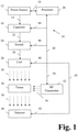
- Fig. 1 provides a schematic diagram of a first contemplated example of a MRI device 10 for use in the present invention.
- the MRI device 10 includes a power source 12.
- the power source 12 may be any type of generator suitable for generating power to be provided to the one or more of the components connected thereto.
- the generator may provide an alternating current (AC) or a direct current (DC), as should be appreciated by those skilled in the art.
- the precise output of the power source 10 is not critical to the operation of the present invention.
- the power output, once generated, may be converted different types (e.g., AC or DC) as required by individual components of the system.
- the power source 12 is illustrated as providing power to each of the various components of the MRI device 10 of the present invention. It is noted, however, that the depicted arrangement is meant to be illustrative only. As should be appreciated by those skilled in the art, the individual components of the MRI device 10 may receive power from a centralized source, such as the power source 12. Alternatively, the various components may receive power from alternative power sources. Accordingly, the depiction of a single power source 12 is not intended to be limiting of the invention.
- the MRI device 10 is illustrated and discussed with reference to single communication lines (or links) extending between the various components.
- the illustration of single communication lines is meant to simplify the discussion and illustration of the various embodiments of the invention.
- the communication lines are not intended to be limited to wired links. To the contrary, the communication lines may be wireless, as required or desired for operation of the MRI device 10.
- the power source 12 may include a plurality of power sources 12, each of which generates power with different characteristics, as required by the device(s) and/or components associated therewith.
- power from the power source 12 travels in two directions. Power from the power source 12 is conducted first along a communication line 14 to a capacitor 16. Power from the power source 12 is carried second along a communication line 18 to a processor 20.
- the capacitor 16 may be of any size or type as would be appreciated by those skilled in the art. As is its nature, the capacitor 16 stores a charge based on the power inputted from the power source 12. That charge is eventually discharged, as discussed in greater detail below.
- Fig. 1 illustrates a single capacitor 16, a plurality of capacitors 16 may be employed without departing from the scope of the present invention.
- the MRI device 10 relies upon a plurality of capacitors 16 for its operation.
- plural sets of capacitors 16 may be employed to generate successive magnetic field gradients.
- the processor 20 may be of any type suitable for executing instructions, generating data, receiving data, storing data, and the like.
- the processor 12 may be a personal computer. Alternatively, the processor 12 may be a mainframe computer, a portable computer, a personal data assistant ("PDA") or any other similar device.
- PDA personal data assistant
- the exact design and functionality of the processor 12 is not critical to operation of the present invention. Accordingly, the processor 12 may be of any type suitable for the operation of the MRI device 10.
- the capacitor 16 is connected, via a communication line 22, to a switch, where the term switch refers to one or more high-power solid-state switch modules as described above. Accordingly, when the capacitor 16 discharges the stored charge, the stored charge passes through the communication line 22 to the switch 24.
- the switch 24 is connected, via a communication line 26, to a coil 28. Accordingly, when the capacitor 16 is discharged, energy from the capacitor 16 is passed to the coil 28, which generates a magnetic field 30.
- the coil 28 need not be a single coil. To the contrary, it is contemplated that the coil 28 may include a plurality of coils 28, each of which is capable of generating all or part of the magnetic field 30. Moreover, as should be appreciated by those skilled in the art, where plural coils 28 are employed, the coils 28 need not be of the same type or size. To the contrary, it is contemplated that, where plural coils 28 are employed, they may be differ from one another to produce magnetic field gradients of differing magnitudes, periods, etc.
- the MRI device 10 includes an RF transmitter 32.
- the RF transmitter 32 generates radio waves 34. While one RF transmitter 32 is illustrated, it is contemplated that a plurality of RF transmitters 32 may be employed. Moreover, where plural RF transmitters 32 are employed, they may be of different sizes, types, etc.
- the magnetic field 30 and the RF waves 34 are directed at a tissue sample 36. While the tissue sample 36 may be a portion of an organism, it may also be a complete organism.
- the tissue 36 After interaction of the magnetic field 30 and the RF waves 34 with the tissue 36, the tissue 36 generates a responsive signal 38 that is detected by the detector 40.
- the signal 38 may encompass a multitude of different signals from the tissue 36.
- the detector 40 detects the signals 38 and passes the signals 38 to the processor 20 via the communication line 42.
- the processor 20 receives and processes the signals 38 to generate an image representative of the composition of the tissue 36.
- the processor 20 may not be the device that processes the signals 38 to generate the image of the tissue 36.
- the detector 40 may be combined with a suitable imaging device.
- the imager may be a component separate from the processor 20 and the detector 40.
- the MRI device 10 includes communication line 42.
- Communication line 42 is illustrated as a central bus that connects the processor 20 to the capacitor via communication line 44, to the switch, via communication line 46, to the coil, via communication line 48, and to the RF transmitter, via communication line 50.
- a central bus is not required to practice the invention. To the contrary, multiple connections may be established between the components of the MRI device 10.
- the communication lines 14, 18, 22, 26, 42, 44, 46, 48, 50 all may conduct data and/or power.
- the communication lines therefore, are meant to illustrate multimodal connections between the various components of the MRI device 10.
- each of the communication lines 14, 18, 22, 26, 42, 44, 46, 48, 50 may be replaced with one or more separate connections, as required or desired.
- the communication lines 14, 18, 22, 26, 42, 44, 46, 48, 50 may be unidirectional or bidirectional as required or desired.
- the processor 20 will provide operating instructions to one or more of the components to which it is connected.
- Fig. 2 illustrates a second example of an MRI device 52 suitable for use in the present invention.
- Many of the components of the MRI device 52 are the same as illustrated and described in connection with MRI device 10 in Fig. 1 . As a result, those components are provided with the same reference numbers as the components in Fig. 1 . Moreover, the descriptions of these components is not repeated for the sake of brevity.
- the MRI device in Fig. 2 differs from the MRI device 10 in Fig. 1 in at least one respect.
- the capacitor 16 and the switch 24 have been replaced with a pulse-forming line 54.
- the pulse-forming line 54 may include one or more capacitors and switches.
- the pulse forming line 54 is connected to the power source 12 via communication line 56.
- the pulse forming line 54 is connected to the coil 28 via the communication line 58.
- the pulse forming line 54 connects to the processor via the communication line 60.
- Pulse forming lines 54 are transmission lines that begin draining their charge in response to a triggering event, such as when triggered by a solid-state switch. Pulse forming lines 54 also are referred to as pulse forming networks.
- a pulse forming network (“PFN”) accumulates electrical energy over a predetermined period of time and releases the electrical energy in the form of a square pulse in a relatively short period of time, depending upon the materials that make up the PFN 54.
- PFNs 54 also may be engineered to provide pulsed power.
- a PFN 54 may be charged by a high voltage power source 12 and then rapidly discharged (possibly via a high voltage switch).
- the pulse forming line 54 may be a single line or may be a plurality of lines combined together.
- the pulse forming line 54 also may be a pulse forming network 54, as discussed above.
- the exact composition and construction of the PFN 54 is not critical to operation of the present invention.
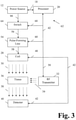
- Fig. 3 illustrates a third example of an MRI device 62. This example is similar to the MRI device 52 illustrated in Fig. 2 . In this third example, however, a switch 64 has been added between the power source 12 and the pulse forming line 54. As illustrated, the power source is connected to the switch via a communication line 66. The switch 65, in turn, is connected to the processor 20 via the communication line 68. As noted above, the switch 65 may be employed to trigger the pulse forming line 54 to release its energy to the coil 28.
- Fig. 4 illustrates a fourth example of an MRI device 70.
- This fourth example is a modification of the MRI device 62, which is illustrated in Fig. 3 .
- a capacitor 72 has been inserted between the switch 64 and the power source 12.
- the capacitor 72 connects to the power source via the communication line 74.
- the capacitor 72 connects to the processor via the communication line 76.
- the capacitor 72 will discharge power to the switch 64, which will discharge power through the pulse forming line 54 to the coil 28, as illustrated.
- connection between the power source 12 and the coil 28 is considered to be a controlled communication line.
- the examples provide variations for contemplated constructions of that controlled communication line.
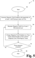
- Fig. 5 illustrates a method 78 outside the scope of the present invention.
- the method 78 starts at 80 and ends at 88. Following the start 80, at 82, a magnetic field gradient with a minimum amplitude of 1 milliTesla per meter (mT/m) is generated. At 84, the magnetic field gradient is maintained for a least about 1 microsecond and up to about 10 milliseconds (this is the plateau time period, as discussed below). At 86, the magnetic field gradient is changed in a time frame small enough to fail to solicit a response from neurological tissue.
- a decision point 85 follows the operation identified at 86. As the flow chart in Fig. 5 indicates, via the decision point 85, steps 84 and 86 are repeated as necessary to obtain physiological and/or anatomic information about tissues. If the pulse sequence is sufficient to obtain the necessary physiological and/or anatomic information about tissues, then the method 78 ends at 88.
- the present invention permits the application of a magnetic field gradient higher than that permitted using existing technology, because the present invention relies, at least in part on shorter rise-and fall-times than available in the prior art.
- the present invention comprises generating a sequence of magnetic field gradient pulses of an amplitude of at least 200 milliTesla per meter and not more than 1000 milliTesla per meter, wherein the magnetic field gradient is maintained at said amplitude during a plateau time period of at least one microsecond, and changed during rise- and fall-times both of less than 10 microseconds.
- Fig. 6 is a graphical illustration of a single magnetic field gradient pulse according to the prior art.
- the rise-time t rise (approximately 150 microseconds) and fall-time t fall (approximately 150 microseconds) of the magnetic field gradient pulse exceed a neurological response time t response for neurological tissue at a typical magnetic field slew rate S typical .
- S typical is 400 T/m/s.
- Data acquisition is typically performed during the plateau phase, because of difficulties in deconvolving the effects of the changing gradient field.
- the most useful portion of the pulse is the plateau time, t plateau .
- the pulse duration includes both the rise and fall times as well as the plateau time, for a typical total duration of 500 microseconds. It should, therefore, be apparent that shortening the rise and fall times can reduce overall scan time.
- Fig. 7 provides a graphical illustration of a magnetic field gradient pulse generated according to the present invention.
- the shortened pulse rise-time duration t short_rise is less than the rise-time t rise according the practice in the prior art.
- the current invention typically would employ a t short_rise of 10 microseconds or less.
- the shortened pulse fall-time duration t short_fall is less than the fall-time t fall according the practice in the prior art.
- the current invention employs a t short_fall of 10 microseconds or less.
- the pulse ramp times t short_rise and t short _ fall are less than the neurological response time t response for neurological tissue at a typical magnetic field slew rate S typical .
- the slew rate in the present invention is increased as a result of the reduced pulse ramp times.
- the plateau magnitude is increased, as compared to the prior art, because of several factors. Firstly, the plateau magnitude may be increased because of the improved switching techniques as described above. Secondly, the plateau magnitude may be increased because the tissues are depolarized and repolarized within a short period of time similar to to the neurological response time t response , in a multi-phasic train of pulses as prescribed by the model according to Reilly.
- the short duration of the time periods t short _ rise and t short_fall make possible the application of a large magnitude magnetic pulse without soliciting a biological response from neurological tissue.
- it is the change in the magnetic field that elicits a biological response.
- the effects on the biological tissue may be minimized such that there is little or no biological response from the tissue.
- the magnitude of the pulse during the time period t plateau may be any value. As discussed above, outside the scope of the present invention, the magnitude may be as small as 1 mT/m. It is contemplated that the magnitude may be smaller or greater than 1 mT/m, as required or desired for a particular application. While the magnitude of the magnetic field is theoretically unbounded at its upper limit, it is foreseeable that the magnitude may be 1000 mT/m or less.
- the duration of the time periods t short_rise and t short_fall will fall in a range between about 1 and about 10 microseconds. As noted above, 10 microseconds is a sufficiently short time period in which to change a magnetic field so that tissue does not react biologically. Naturally, the shorter the duration of t short_rise and t short_fall , the smaller the likelihood of eliciting a biological response. In keeping with this premise, it is contemplated that the invention will operate with one or both of the time periods, t short_rise and t short_fall , being less than about 9 microseconds. In another contemplated embodiment, one or both of the time periods is less than about 8 microseconds.
- one or both of the time periods is less than about 7 microseconds. Further, the time periods are less than about 6 microseconds in another contemplated embodiment. In one other contemplated embodiment, one or both of the time periods is less than about 5 microseconds. One or both of the time periods may be less than about 4 microseconds in yet another contemplated embodiment. Still further, it is contemplated that one or both of the time periods is less about than 3 microseconds. In an additional contemplated embodiment, one or both time periods is less than about 2 microseconds. In one further contemplated embodiment, one or both of the time periods is less than about 1 microsecond. As should be apparent, the time periods, t short_rise and t short_fall , need not be identical in duration. The variable t short_rise may be greater than, equal to, or less than the variable t short _ fall without departing from the scope of the present invention.
- the shortening of overall scan times is effected through at least mechanisms in the present invention: Firstly, the reduced rise- and fall-times lead to an overall reduction in scan time. Secondly, the higher plateau magnitude allows the MRI system to acquire data of quality comparable to the prior art using a shorter plateau time t short_plateau .
- FIGs. 6 and 7 A comparison between Figs. 6 and 7 also illustrate one further aspect of the present invention. Specifically, the magnetic field gradient as generated by the prior art is about 5 times weaker than the magnetic field gradient generated by the MRI device 10 of the present invention.
- the invention includes a method of decreasing bio-effects in magnetic resonance imaging through the use of reduced pulse lengths and multi-phasic magnetic gradient pulses.
- the magnetic pulses are created by releasing electrical charge stored in capacitors and/or transmission lines into coils and/or transmission lines near a body part.
- the coils may include dielectric and/or ferrite materials which assist in the shaping of the magnetic pulses. Ferrite materials may be used to construct complex dynamic electromagnetic fields for circulators and other circuit elements employed in microwave transmission and receivers (as disclosed by Ansoft Corporation, in Microwave Journal, June, 1996 ).
- the invention differs from the prior art by prescribing multi-phasic pulse trains within a short period of time similar to the neurological response time t response , unlike the pulse sequences previously taught.
Landscapes
- Physics & Mathematics (AREA)
- Condensed Matter Physics & Semiconductors (AREA)
- General Physics & Mathematics (AREA)
- Magnetic Resonance Imaging Apparatus (AREA)
Description
- The present invention concerns a method for decreasing the bioeffects of magnetic field gradients on tissue(s). More specifically, the present invention concerns a method to decrease bio-effects on neurological tissue from magnetic field gradients, such as those experienced during Magnetic Resonance Imaging ("MRI").
- As should be appreciated by those skilled in the art, MRI is a technology whereby a magnetic field gradient is applied to subatomic particles in tissue to spatially encode a subsequent response from the atoms and molecules in the tissue to a radiofrequency pulse. After detection of an electromagnetic response from the tissue, an image of the tissue is generated partly based on that response.
- CONRADI MS ET AL: "GENERATION OF SHORT, INTENSE GRADIENT PULSES", JOURNAL OF MAGNETIC RESONANCE, ACADEMIC PRESS, ORLANDO, FL, US, vol. 94, no. 2, 1 September 1991 (1991-09-01), pages 370-375, ISSN: 1090-7807 refers to experiments with gradient pulses of approximately 3 µs long with peak amplitudes of up to 0.2 T /m. While P.T. et al., Phys.Med.Biol. 49 (2004), 2779-2798 refers to studies investigating rise times considerably longer than 100 µs where reduction of the rise time does increase magnetic stimulation. Results from a model are reported suggesting that there is a finite limit to electric field strength of about 10.4 V/m as rise time approaches zero.
- Unfortunately, the generation of magnetic field gradients (e.g., switching gradients) may elicit undesirable responses in a living organism by induction of electrical pulses in nerves and other electrically-sensitive tissues.
- A model describing electromagnetic bio-effects was described by DR McNeal and JP Reilly in the mid to late 1970's (DR McNeal, "Analysis of a model for excitation of myelinated nerve," in IEEE Trans. Biomed. Eng., 23:329-337, 1976; and JP Reilly, "Electric and Magnetic field coupling from high voltage AC power transmission lines - Classification of shortterm effects on people," in IEEE Trans. on Power Apparatus and Systems, 97(6): 2243-2252, 1978) based on classic membrane-excitability relations (AL Hodgkin and AF Huxley, "A quantitative description of membrane current and its application to conduction and excitation in nerve," in J. Physiol., 117:500-544, 1952).
- Subsequent elaborations of the model were disclosed by Reilly in "Sensory effects of transient electrical stimulation: Evaluation with a neuroelectric model," IEEE Trans. Biomed. Eng., 32(12) 1001:1011, 1985.
- The model elaborated by Reilly invokes the telegraph equation first applied in the late 1800's to design trans-Atlantic cables.
- As in underwater cables, neurons are organized in sections that are separated by nodes of Ranvier. These nodes enforce resistance/capacitance ("RC") equations that govern neuronal behavior, with time constants related to neuronal diameter and inter-nodal distances.
- Having provided a brief overview of the electrical characteristics, attention is now turned to magnetic field gradients.
- With respect to MRI, magnetic field gradients have at least one component of particular interest: the slew rate. The slew rate refers to the rate of change in the magnitude of the gradient, which is typically measured in Teslas per meter per second (T/m/s).
- As the laws of physics dictate, changes in magnetic fields result in the generation of electrical fields. Changes in magnetic field gradients in tissue, therefore, also result in the formation of electric fields.
- When studying neurological tissues, the changes in magnetic field gradients depolarize nerves, once a threshold is reached. This threshold becomes higher as the pulse duration becomes shorter. The relationship between these variables follows a traditional, hyperbolic curve.
- It is noted that experimental studies in humans (D.J. Schaefer, J.D. Bourland, and J.A. Nyenhuis, "Review of Patient Safety in Time-Varying Gradient Fields," in J. Magnetic Resonance Imaging, 12:20-29, 2000) have validated the basic model for pulse durations as short as fifty microseconds.
- In response to various MRI studies, regulatory agencies have codified the strength-duration model into law, at least in Europe and the United States. (See Requirements for the Safety of MR Equipment for Medical Diagnosis, IEC 60601-2-33 (with respect to Europe); see also Guidelines for Premarket Notifications for MR Diagnostic Devices, 21 C.F.R. § 807.87 (with respect to the US).)
- As a result of these studies and as a result of the regulations that are based on these studies, MRI manufacturers have attempted to design triangular pulse sequences to conform to the limits prescribed by the Reilly model, among others.
- One such attempt is described in
U.S. Patent No. 6,198,282 , which is directed to an optimized gradient system for providing minimum-duration gradient pulses. - The prior art also includes evidence of interest in the strength-duration curve from another direction, as manufacturers of neuron-stimulators try to shape the pulse in order to increase stimulation. (See P.J. Maccabee, "Influence of pulse sequence, polarity and amplitude on magnetic stimulation of human and porcine peripheral nerve," J. Physiol., 513:571-585, 1998).
- As a result of numerous studies and advancements, those in the industry traditionally have applied magnetic field gradients less than a threshold for neuronal stimulation. As a result of the reduced gradient magnitude, the MRI diagnosis takes longer, and has reduced spatial resolution, than it would otherwise have with a higher magnetic gradient field strength.
- There appears to be wide acceptance in the MRI community in the belief that the attainment of high gradient slew rates (i.e., the change in magnetic gradients over a short period of time) would be a welcome development for the industry.
- As should be immediately apparent, one impetus for increasing slew rates is to reduce scan time. It is postulated that, if a given MRI sequence requires a certain number of pulses, then the application of shorter (but stronger) pulses, and of pulses with shorter ramp times, would permit the MRI sequence to be completed in a shorter time period (i.e., faster) than conventional techniques.
- Among other benefits, saving time improves safety for unstable patients. Saving time also may reduce the cost of the MRI sequence.
- A second incentive for increasing slew rate is to increase gradient field strength, which improves spatial resolution. For a given prescribed pulse sequence, the faster one can ramp up the magnetic field per pulse, the higher the gradient strength will be for the same overall scan time. Since the gradient strength is proportional to the spatial resolution of the MRI image obtained, a higher slew rate will result in a better spatial resolution. Increased spatial resolution may improve medical diagnosis in some cases.
- As discussed above, for manufacturers of MRI devices, limits have been set for slew rates based on studies concerning the presence of bio-effects due to neuronal stimulation. These limits have placed a limit on currently-available scanning technologies.
- As also should be appreciated by those skilled in the art, the generation of a magnetic field gradient with a very small duration presents technological challenges as well. Accordingly, there also has been a technological barrier to decreasing the duration of the magnetic field gradient pulses.
- With respect to technological limitations, in some MRI devices, switches are used to trigger the generation of a magnetic field gradient. The types of switches traditionally used include Insulated-Gate Bipolar Transistor ("IGBT") and Metal Oxide Semiconductor Field Effect Transistor ("MOSFET")-based devices. However, these traditional switches are not capable of creating magnetic filed gradients with a sufficiently short duration to avoid neuronal stimulation.
- Recent developments in switches offer a solution to the technological problem experienced with prior art MRI devices.
- Specifically, several generations of plasma physics experimentalists have led the development of reliable solid-state switches and pulse-forming lines that are just now being introduced into the community. (See H. Sanders and S. Glidden, "High Power Solid State Switch Module," in International Power Modulator Symposium Conference Record, pp. 563-566, 2004).
- Those high-power solid-state switches are capable of triggering pulses of tenthousand amps in one microsecond, orders of magnitude higher than the IGBT and MOSFET-based systems currently employed in commercial gradient field generators for MRI systems (See D.A. Seeber, J.H. Hoftiezer, and C.H. Pennington, "Pulsed current gradient power supply for microcoil magnetic resonance imaging," in Magnetic Resonance Engineering, 15(3): 189-200, 2002).
- It is axiomatic in the field of pulsed power technology that it is often easier to close a switch than to open a switch. To get around this limitation, solid-state switches may be combined with pulse-forming lines ("PFLs"), which do not require opening switches.
- PFLs, which are also known as Blumlein lines (named for the World-War II-era inventor David Blumlein), are dielectric-filled transmission lines that begin draining their charge when triggered by a solid-state switch. The transmission lines stop delivering current once the dielectric has been drained of charge. Blumlein lines can switch in nanoseconds, and maintain currents for milliseconds. (K Gasthaus, "A millisecond Blumlein line for the power supply of a high power laser," in J. Phys. E: Instrum., 20:192-195, 1987). In order to deliver pulses of varying widths, sets of PFLs may be triggered independently of one another into a common load.
- In view of the foregoing, there exists a desire to apply higher magnetic field gradients to tissue in an MRI environment while avoiding adverse bio-effects on that tissue.
- It is, therefore, one aspect of the present invention to provide a method for decreasing the duration of scan times for MRI. method in accordance with the invention is defined in
claim 1. - An additional aspect of the present invention involves the application of magnetic field gradients with a magnitude greater than that traditionally employed. In one embodiment, the gradient may be up to five (5) times greater than previously applied. In other embodiments, the magnitude may be greater.
- It is another aspect of the present invention to decrease bio-effects from magnetic field gradients by applying a magnetic field gradient to tissue within a time frame below the response threshold for that tissue.
- Among other things, the current invention takes advantage of a physiological loophole: according to accepted physiological models for ionic channel transport, bi-phasic pulses on the order of a microsecond are too fast for the nerve to change its polarization state, and are, therefore, effectively ignored. The present invention capitalizes on this physiological loophole.
- According to the model elaborated by Reilly, this loophole implies that gradient field thresholds may be increased by factors of five or more above the usual hyperbolic model without triggering any bio-effects.
- The present invention also takes advantage of magnetic pulse delivery systems that are more powerful than traditional systems used to deliver MRI pulses.
- In one contemplated embodiment, the present invention utilizes solid-state switch and/or PFL technologies that conform to the requirements of MRI gradient amplifiers. These requirements include increased repetition rates, impedance and trigger matching to MRI pulse programming consoles, and electrical/acoustic noise shielding considerations. Downstream modifications include the buttressing of gradient coils to handle the higher electromagnetic (i.e., J x B) forces that will occur at higher current loads, especially in high resolution MRI systems with high static magnetic fields.
- According to classic coil-design codes, eddy current shielding is likely to be less of a problem than at current regimes, and reductions in inductance are predicted. The influence of eddy currents may further be minimized by acquiring signals at long echo time ("TE"), when eddy currents have died down, as contemplated by still another embodiment of the present invention.
- In one further contemplated embodiment, the bore of the cryostat may be made significantly larger than the gradient coil, further reducing the influence of eddy currents.
- Other advantages of the present invention will be made apparent from the discussion that follows and will be appreciated by those skilled in the art.
- The invention will now be described in connection with the drawings appended hereto, in which:
-
Fig. 1 is a schematic illustration of a first example of an apparatus for use in the present invention; -
Fig. 2 is a schematic illustration of a second example of an apparatus for use in the present invention; -
Fig. 3 is a schematic illustration of a third example of an apparatus for use in the present invention; -
Fig. 4 is a schematic illustration of a fourth example of an apparatus for use in the present invention; -
Fig. 5 is a flow chart illustrating a method for generating a magnetic field gradient; -
Fig. 6 is a graph depicting the magnetic field gradient and duration typical of a prior art MRI device as used clinically; and -
Fig. 7 is a graph depicting the magnetic field gradient and duration contemplated by the present invention. - The present invention will now be described in connection with one or more embodiments. It is intended for the embodiments to be representative of the invention and not limiting of the scope of the invention. The invention is intended to encompass equivalents and variations, as should be appreciated by those skilled in the art.
- As a prelude to the discussion of the various embodiments of the present invention, a general discussion of MRI devices is now provided. This overview is not intended to be limiting of the invention. It is provided merely to assist with an understanding of the components of the various embodiment of the present invention, as detailed below.
- As a general rule, an MRI device includes a magnetic field generator, typically a magnetic coil and a radio frequency ("RF") generator or transmitter. The magnetic coil generates a time-varying magnetic field and the RF generator emits radio waves. The MRI device typically also applies a static magnetic field.
- As should be appreciated by those skilled in the art, tissue is primarily composed of water molecules, each of which contains hydrogen atoms. When a person's tissue is exposed to a strong magnetic field, the hydrogen atoms align with the direction of the magnetic field. Subsequently, the RF generator emits radio waves to the hydrogen atoms while in the aligned state. Some of the energy from the radio waves is absorbed by the hydrogen atoms in the water molecules, thereby altering the magnetic alignment of the hydrogen atoms. The altered magnetic state is detected by the detector, which generates signals that are processed to form as an image.
- With this overview in mind, reference is now made to
Fig. 1. Fig. 1 provides a schematic diagram of a first contemplated example of aMRI device 10 for use in the present invention. - The
MRI device 10 includes apower source 12. Thepower source 12 may be any type of generator suitable for generating power to be provided to the one or more of the components connected thereto. The generator may provide an alternating current (AC) or a direct current (DC), as should be appreciated by those skilled in the art. The precise output of thepower source 10 is not critical to the operation of the present invention. Moreover, the power output, once generated, may be converted different types (e.g., AC or DC) as required by individual components of the system. - In
Fig. 1 , thepower source 12 is illustrated as providing power to each of the various components of theMRI device 10 of the present invention. It is noted, however, that the depicted arrangement is meant to be illustrative only. As should be appreciated by those skilled in the art, the individual components of theMRI device 10 may receive power from a centralized source, such as thepower source 12. Alternatively, the various components may receive power from alternative power sources. Accordingly, the depiction of asingle power source 12 is not intended to be limiting of the invention. - In addition, as detailed below, the
MRI device 10 is illustrated and discussed with reference to single communication lines (or links) extending between the various components. The illustration of single communication lines is meant to simplify the discussion and illustration of the various embodiments of the invention. As should be appreciated by those skilled in the art, there may be multiple communication lines between the various components of theMRI device 10 as required for their operation. Moreover, the communication lines are not intended to be limited to wired links. To the contrary, the communication lines may be wireless, as required or desired for operation of theMRI device 10. - The
power source 12 may include a plurality ofpower sources 12, each of which generates power with different characteristics, as required by the device(s) and/or components associated therewith. - As depicted in
Fig. 1 , power from thepower source 12 travels in two directions. Power from thepower source 12 is conducted first along acommunication line 14 to acapacitor 16. Power from thepower source 12 is carried second along acommunication line 18 to aprocessor 20. - The
capacitor 16 may be of any size or type as would be appreciated by those skilled in the art. As is its nature, thecapacitor 16 stores a charge based on the power inputted from thepower source 12. That charge is eventually discharged, as discussed in greater detail below. - While
Fig. 1 illustrates asingle capacitor 16, a plurality ofcapacitors 16 may be employed without departing from the scope of the present invention. In one contemplated embodiment, theMRI device 10 relies upon a plurality ofcapacitors 16 for its operation. As should be appreciated by those skilled in the art, plural sets ofcapacitors 16 may be employed to generate successive magnetic field gradients. - In the second flow path, power from the
power source 12 is provided to theprocessor 20. Theprocessor 20 may be of any type suitable for executing instructions, generating data, receiving data, storing data, and the like. Theprocessor 12 may be a personal computer. Alternatively, theprocessor 12 may be a mainframe computer, a portable computer, a personal data assistant ("PDA") or any other similar device. The exact design and functionality of theprocessor 12 is not critical to operation of the present invention. Accordingly, theprocessor 12 may be of any type suitable for the operation of theMRI device 10. - The
capacitor 16 is connected, via acommunication line 22, to a switch, where the term switch refers to one or more high-power solid-state switch modules as described above. Accordingly, when thecapacitor 16 discharges the stored charge, the stored charge passes through thecommunication line 22 to theswitch 24. - The
switch 24 is connected, via acommunication line 26, to acoil 28. Accordingly, when thecapacitor 16 is discharged, energy from thecapacitor 16 is passed to thecoil 28, which generates amagnetic field 30. - The
coil 28 need not be a single coil. To the contrary, it is contemplated that thecoil 28 may include a plurality ofcoils 28, each of which is capable of generating all or part of themagnetic field 30. Moreover, as should be appreciated by those skilled in the art, whereplural coils 28 are employed, thecoils 28 need not be of the same type or size. To the contrary, it is contemplated that, whereplural coils 28 are employed, they may be differ from one another to produce magnetic field gradients of differing magnitudes, periods, etc. - As also shown in
Fig. 1 , theMRI device 10 includes anRF transmitter 32. As discussed briefly above, theRF transmitter 32 generatesradio waves 34. While oneRF transmitter 32 is illustrated, it is contemplated that a plurality ofRF transmitters 32 may be employed. Moreover, whereplural RF transmitters 32 are employed, they may be of different sizes, types, etc. - As illustrated, the
magnetic field 30 and the RF waves 34 are directed at atissue sample 36. While thetissue sample 36 may be a portion of an organism, it may also be a complete organism. - After interaction of the
magnetic field 30 and the RF waves 34 with thetissue 36, thetissue 36 generates aresponsive signal 38 that is detected by thedetector 40. As should be appreciated by those skilled in the art, thesignal 38 may encompass a multitude of different signals from thetissue 36. Thedetector 40 detects thesignals 38 and passes thesignals 38 to theprocessor 20 via thecommunication line 42. Theprocessor 20 receives and processes thesignals 38 to generate an image representative of the composition of thetissue 36. - As should be appreciated by those skilled in the art, the
processor 20 may not be the device that processes thesignals 38 to generate the image of thetissue 36. To the contrary, thedetector 40 may be combined with a suitable imaging device. The imager may be a component separate from theprocessor 20 and thedetector 40. - With continued reference to
Fig. 1 , theMRI device 10 includescommunication line 42.Communication line 42 is illustrated as a central bus that connects theprocessor 20 to the capacitor viacommunication line 44, to the switch, viacommunication line 46, to the coil, viacommunication line 48, and to the RF transmitter, viacommunication line 50. A central bus, however, is not required to practice the invention. To the contrary, multiple connections may be established between the components of theMRI device 10. - It is noted that the
communication lines MRI device 10. As noted above, each of thecommunication lines - With respect to the
communication lines processor 20 will provide operating instructions to one or more of the components to which it is connected. Theprocessor 20, therefore, is contemplated to incorporate control functionality over one or more of the components, as should be appreciated by those skilled in the art. It is also contemplated that controls may be fed from one component to another, as required or desired for operation of theMRI device 10. -
Fig. 2 illustrates a second example of anMRI device 52 suitable for use in the present invention. Many of the components of theMRI device 52 are the same as illustrated and described in connection withMRI device 10 inFig. 1 . As a result, those components are provided with the same reference numbers as the components inFig. 1 . Moreover, the descriptions of these components is not repeated for the sake of brevity. - The MRI device in
Fig. 2 differs from theMRI device 10 inFig. 1 in at least one respect. Specifically, thecapacitor 16 and theswitch 24 have been replaced with a pulse-formingline 54. As should be appreciated by those skilled in the art, the pulse-formingline 54 may include one or more capacitors and switches. Thepulse forming line 54 is connected to thepower source 12 viacommunication line 56. Thepulse forming line 54 is connected to thecoil 28 via thecommunication line 58. Thepulse forming line 54 connects to the processor via thecommunication line 60. - As discussed above, a
pulse forming line 54 is also known as a Blumlein line.Pulse forming lines 54 are transmission lines that begin draining their charge in response to a triggering event, such as when triggered by a solid-state switch.Pulse forming lines 54 also are referred to as pulse forming networks. A pulse forming network ("PFN") accumulates electrical energy over a predetermined period of time and releases the electrical energy in the form of a square pulse in a relatively short period of time, depending upon the materials that make up thePFN 54.PFNs 54 also may be engineered to provide pulsed power. APFN 54 may be charged by a highvoltage power source 12 and then rapidly discharged (possibly via a high voltage switch). - The
pulse forming line 54 may be a single line or may be a plurality of lines combined together. Thepulse forming line 54 also may be apulse forming network 54, as discussed above. The exact composition and construction of thePFN 54 is not critical to operation of the present invention. -
Fig. 3 illustrates a third example of anMRI device 62. This example is similar to theMRI device 52 illustrated inFig. 2 . In this third example, however, aswitch 64 has been added between thepower source 12 and thepulse forming line 54. As illustrated, the power source is connected to the switch via acommunication line 66. The switch 65, in turn, is connected to theprocessor 20 via thecommunication line 68. As noted above, the switch 65 may be employed to trigger thepulse forming line 54 to release its energy to thecoil 28. -
Fig. 4 illustrates a fourth example of anMRI device 70. This fourth example is a modification of theMRI device 62, which is illustrated inFig. 3 . Here, acapacitor 72 has been inserted between theswitch 64 and thepower source 12. Thecapacitor 72 connects to the power source via thecommunication line 74. Thecapacitor 72 connects to the processor via thecommunication line 76. In this embodiment, it is contemplated that thecapacitor 72 will discharge power to theswitch 64, which will discharge power through thepulse forming line 54 to thecoil 28, as illustrated. - With respect to the examples illustrated in
Figs. 1 ,2 ,3 , and4 , and for purposes of the present invention, the connection between thepower source 12 and thecoil 28 is considered to be a controlled communication line. As a result, the examples provide variations for contemplated constructions of that controlled communication line. -
Fig. 5 illustrates amethod 78 outside the scope of the present invention. Themethod 78 starts at 80 and ends at 88. Following thestart 80, at 82, a magnetic field gradient with a minimum amplitude of 1 milliTesla per meter (mT/m) is generated. At 84, the magnetic field gradient is maintained for a least about 1 microsecond and up to about 10 milliseconds (this is the plateau time period, as discussed below). At 86, the magnetic field gradient is changed in a time frame small enough to fail to solicit a response from neurological tissue. Adecision point 85 follows the operation identified at 86. As the flow chart inFig. 5 indicates, via thedecision point 85, steps 84 and 86 are repeated as necessary to obtain physiological and/or anatomic information about tissues. If the pulse sequence is sufficient to obtain the necessary physiological and/or anatomic information about tissues, then themethod 78 ends at 88. - As discussed in greater detail below, it is contemplated that application of the magnetic field gradient with rise- and fall- times of less than about 10 microseconds will establish suitable conditions to avoid triggering a biological response from neurological tissue. As should be appreciated by those skilled in the art, and as discussed in greater detail below, the present invention permits the application of a magnetic field gradient higher than that permitted using existing technology, because the present invention relies, at least in part on shorter rise-and fall-times than available in the prior art. More specifically, the present invention comprises generating a sequence of magnetic field gradient pulses of an amplitude of at least 200 milliTesla per meter and not more than 1000 milliTesla per meter, wherein the magnetic field gradient is maintained at said amplitude during a plateau time period of at least one microsecond, and changed during rise- and fall-times both of less than 10 microseconds.
-
Fig. 6 is a graphical illustration of a single magnetic field gradient pulse according to the prior art. The rise-time trise (approximately 150 microseconds) and fall-time tfall (approximately 150 microseconds) of the magnetic field gradient pulse exceed a neurological response time tresponse for neurological tissue at a typical magnetic field slew rate Stypical. For a typical clinical system, Stypical is 400 T/m/s. Data acquisition is typically performed during the plateau phase, because of difficulties in deconvolving the effects of the changing gradient field. As a result, the most useful portion of the pulse is the plateau time, tplateau. The pulse duration includes both the rise and fall times as well as the plateau time, for a typical total duration of 500 microseconds. It should, therefore, be apparent that shortening the rise and fall times can reduce overall scan time. - As should be appreciated by those skilled in the art, the terms "rise" and "fall" may be applied to both negative- and positive-generated pulses.
-
Fig. 7 provides a graphical illustration of a magnetic field gradient pulse generated according to the present invention. The shortened pulse rise-time duration tshort_rise is less than the rise-time trise according the practice in the prior art. The current invention typically would employ a tshort_rise of 10 microseconds or less. The shortened pulse fall-time duration tshort_fall is less than the fall-time tfall according the practice in the prior art. The current invention employs a tshort_fall of 10 microseconds or less. Also, the pulse ramp times tshort_rise and tshort_fall are less than the neurological response time tresponse for neurological tissue at a typical magnetic field slew rate Stypical. The slew rate in the present invention is increased as a result of the reduced pulse ramp times. In the present invention, the plateau magnitude is increased, as compared to the prior art, because of several factors. Firstly, the plateau magnitude may be increased because of the improved switching techniques as described above. Secondly, the plateau magnitude may be increased because the tissues are depolarized and repolarized within a short period of time similar to to the neurological response time tresponse, in a multi-phasic train of pulses as prescribed by the model according to Reilly. - As should be apparent, the short duration of the time periods tshort_rise and tshort_fall make possible the application of a large magnitude magnetic pulse without soliciting a biological response from neurological tissue. As discussed above, it is the change in the magnetic field that elicits a biological response. With a rapid change in magnetic field strength, the effects on the biological tissue may be minimized such that there is little or no biological response from the tissue.
- It is contemplated that the magnitude of the pulse during the time period tplateau may be any value. As discussed above, outside the scope of the present invention, the magnitude may be as small as 1 mT/m. It is contemplated that the magnitude may be smaller or greater than 1 mT/m, as required or desired for a particular application. While the magnitude of the magnetic field is theoretically unbounded at its upper limit, it is foreseeable that the magnitude may be 1000 mT/m or less.
- As for the duration of the time periods tshort_rise and tshort_fall, it is contemplated that these time periods will fall in a range between about 1 and about 10 microseconds. As noted above, 10 microseconds is a sufficiently short time period in which to change a magnetic field so that tissue does not react biologically. Naturally, the shorter the duration of tshort_rise and tshort_fall, the smaller the likelihood of eliciting a biological response. In keeping with this premise, it is contemplated that the invention will operate with one or both of the time periods, tshort_rise and tshort_fall, being less than about 9 microseconds. In another contemplated embodiment, one or both of the time periods is less than about 8 microseconds. In still another contemplated embodiment, one or both of the time periods is less than about 7 microseconds. Further, the time periods are less than about 6 microseconds in another contemplated embodiment. In one other contemplated embodiment, one or both of the time periods is less than about 5 microseconds. One or both of the time periods may be less than about 4 microseconds in yet another contemplated embodiment. Still further, it is contemplated that one or both of the time periods is less about than 3 microseconds. In an additional contemplated embodiment, one or both time periods is less than about 2 microseconds. In one further contemplated embodiment, one or both of the time periods is less than about 1 microsecond. As should be apparent, the time periods, tshort_rise and tshort_fall, need not be identical in duration. The variable tshort_rise may be greater than, equal to, or less than the variable tshort_fall without departing from the scope of the present invention.
- In the present invention, the shortening of overall scan times is effected through at least mechanisms in the present invention: Firstly, the reduced rise- and fall-times lead to an overall reduction in scan time. Secondly, the higher plateau magnitude allows the MRI system to acquire data of quality comparable to the prior art using a shorter plateau time tshort_plateau.
- A comparison between
Figs. 6 and 7 also illustrate one further aspect of the present invention. Specifically, the magnetic field gradient as generated by the prior art is about 5 times weaker than the magnetic field gradient generated by theMRI device 10 of the present invention. - In summary, the invention includes a method of decreasing bio-effects in magnetic resonance imaging through the use of reduced pulse lengths and multi-phasic magnetic gradient pulses.
- As discussed, the magnetic pulses are created by releasing electrical charge stored in capacitors and/or transmission lines into coils and/or transmission lines near a body part. The coils may include dielectric and/or ferrite materials which assist in the shaping of the magnetic pulses. Ferrite materials may be used to construct complex dynamic electromagnetic fields for circulators and other circuit elements employed in microwave transmission and receivers (as disclosed by Ansoft Corporation, in Microwave Journal, June, 1996).
- Among other differences, the invention differs from the prior art by prescribing multi-phasic pulse trains within a short period of time similar to the neurological response time tresponse, unlike the pulse sequences previously taught.
- Other aspects of the present invention should be apparent to those skilled in the art based on the discussion provided herein.
Claims (3)
- A method of implementing magnetic resonance imaging of structures containing neurological tissue, wherein the neurological tissue comprises at least a portion of a living organism, the method comprising:
generating and applying to said tissue a sequence of magnetic field gradient pulses of an amplitude of at least 200 milliTesla per meter and not more than 1000 milliTesla per meter, wherein the magnetic field gradient is maintained at said amplitude during a plateau time period of at least one microsecond, and changed during rise- and fall-times both of less than 10 microseconds. - The method of claim 1, wherein the magnetic field gradient pulses are generated using a magnetic field generator for magnetic resonance imaging that comprises at least one power source, at least one coil connected to the at least one power source to generate a time-varying magnetic field, at least one capacitor connected to the coil, wherein the at least one capacitor stores energy from the at least one power source that is applied to the at least one coil, and at least one multi-stage high- voltage switch connected between the capacitor and the coil, wherein the stored energy from the capacitor is delivered to the at least one coil so that the coil generates the magnetic field gradient pulses.
- The method of claim 1, wherein the magnetic field gradient pulses are generated using a magnetic field generator for magnetic resonance imaging that comprises at least one power source, at least one coil connected to the at least one power source to generate a time-varying magnetic field, and at least one pulse- forming network connected between the at least one power source and the at least one coil, wherein the stored energy from the at least one pulse-forming network is delivered to the at least one coil so that the coil generates the magnetic field gradient pulses.
Applications Claiming Priority (2)
| Application Number | Priority Date | Filing Date | Title |
|---|---|---|---|
| US7439708P | 2008-06-20 | 2008-06-20 | |
| PCT/US2009/047960 WO2009155522A1 (en) | 2008-06-20 | 2009-06-19 | Apparatus and method for decreasing bio-effects of magnetic gradient field gradients |
Related Child Applications (1)
| Application Number | Title | Priority Date | Filing Date |
|---|---|---|---|
| EP21164731.8 Division-Into | 2021-03-24 |
Publications (3)
| Publication Number | Publication Date |
|---|---|
| EP2294436A1 EP2294436A1 (en) | 2011-03-16 |
| EP2294436A4 EP2294436A4 (en) | 2011-07-06 |
| EP2294436B1 true EP2294436B1 (en) | 2022-02-09 |
Family
ID=41430573
Family Applications (1)
| Application Number | Title | Priority Date | Filing Date |
|---|---|---|---|
| EP09767831.2A Active EP2294436B1 (en) | 2008-06-20 | 2009-06-19 | Method for decreasing bio-effects of magnetic field gradients |
Country Status (5)
| Country | Link |
|---|---|
| US (1) | US8154286B2 (en) |
| EP (1) | EP2294436B1 (en) |
| CN (1) | CN102171582B (en) |
| ES (1) | ES2907993T3 (en) |
| WO (1) | WO2009155522A1 (en) |
Families Citing this family (18)
| Publication number | Priority date | Publication date | Assignee | Title |
|---|---|---|---|---|
| US9612308B2 (en) | 2008-06-20 | 2017-04-04 | Weinberg Medical Physics Inc | Ultra-fast magnetic field for electron paramagnetic resonance imaging used in monitoring dose from proton or hadron therapy |
| US9411030B2 (en) * | 2008-06-20 | 2016-08-09 | Weinberg Medical Physics Llc | Apparatus and method for decreasing bio-effects of magnetic gradient field gradients |
| US9772387B2 (en) | 2008-06-20 | 2017-09-26 | Weinberg Medical Physics, Inc. | Method and apparatus for high resolution physiological imaging of neurons |
| US8836329B2 (en) * | 2008-06-20 | 2014-09-16 | Weinberg Medical Physics Llc | Ultra-fast pre-polarizing magnetic resonance imaging method and system |
| US9380959B2 (en) | 2011-08-18 | 2016-07-05 | Weinberg Medical Physics Llc | MRI-guided nanoparticle cancer therapy apparatus and methodology |
| EP2994769A4 (en) * | 2013-03-21 | 2017-03-01 | Weinberg Medical Physics LLC | Method and apparatus for high resolution physiological imaging of neurons |
| US9726738B2 (en) | 2013-06-21 | 2017-08-08 | Weinberg Medical Physics Inc. | Energy-saving method of generating time-varying magnetic gradients for use in MRI |
| US10627461B2 (en) | 2014-10-03 | 2020-04-21 | Weinberg Medical Physics Inc | Method and apparatus for image-directed nerve growth |
| US11378632B2 (en) | 2016-02-17 | 2022-07-05 | Weinberg Medical Physics Inc. | Apparatus and method for rapid and comfortable magnetic imaging of breast tissues, with cultural sensitivity |
| CN108814599A (en) * | 2017-03-16 | 2018-11-16 | 温伯格医学物理有限公司 | The method and apparatus of rapid evaluation and processing for wound |
| AU2018279823B2 (en) | 2017-06-08 | 2024-03-28 | Weinberg Medical Physics, Inc. | Unilateral magnetic resonance imaging system with aperture for interventions and methodologies for operating same |
| US11607285B2 (en) * | 2017-08-02 | 2023-03-21 | Weinberg Medical Physics, Inc | Apparatus, system and methodologies for biopsy or removal of tissue or adding material to tissue using a magnetically-actuated capsule |
| CN107608931B (en) * | 2017-08-07 | 2020-09-22 | 三峡大学 | Transmission line transient response rapid calculation method based on Chebyshev quasi-spectrum-secondary boundary value coupling method |
| CN109419509A (en) * | 2017-08-22 | 2019-03-05 | 温伯格医学物理有限公司 | The MRI of free radical from radiation is detected |
| US20190099490A1 (en) * | 2017-10-04 | 2019-04-04 | Weinberg Medical Physics, Inc. | Apparatus and method for magnetic delivery of drugs deep into articular cartilage for osteoarthritis |
| US10888225B2 (en) | 2017-11-10 | 2021-01-12 | Weinberg Medical Physics Inc | Red blood cells as voltage-sensitive contrast agents |
| EP3948323A4 (en) * | 2019-03-25 | 2022-12-21 | Promaxo, Inc. | FAST SINGLE-SIDED MRI FIELD-GRADIENT COILS AND THEIR APPLICATIONS |
| EP4296702A1 (en) * | 2022-06-24 | 2023-12-27 | Bruker Switzerland AG | Split self-shielded gradient coil system, with power supply system for individually adjusting currents of sub-coil groups |
Family Cites Families (12)
| Publication number | Priority date | Publication date | Assignee | Title |
|---|---|---|---|---|
| JPH0246827A (en) * | 1988-08-10 | 1990-02-16 | Toshiba Corp | Device for imaging magnetic resonance |
| US5145163A (en) * | 1989-11-24 | 1992-09-08 | Medrad, Inc. | Film sheet load magazine |
| US5202631A (en) * | 1991-08-09 | 1993-04-13 | Steven E. Harms | Magnetic resonance imaging techniques utilizing multiple shaped radiofrequency pulse sequences |
| US5442290A (en) * | 1992-08-04 | 1995-08-15 | The Regents Of The University Of California | MRI gradient drive current control using all digital controller |
| JP3515205B2 (en) * | 1995-03-15 | 2004-04-05 | 株式会社東芝 | Gradient magnetic field generator for magnetic resonance diagnostic equipment |
| US6198282B1 (en) | 1999-10-07 | 2001-03-06 | General Electric Company | Optimized MRI gradient system for providing minimum-duration gradient pulses |
| US6704594B1 (en) * | 2000-11-06 | 2004-03-09 | Topspin Medical (Israel) Limited | Magnetic resonance imaging device |
| US7859260B2 (en) * | 2005-01-18 | 2010-12-28 | Baker Hughes Incorporated | Nuclear magnetic resonance tool using switchable source of static magnetic field |
| JP5334582B2 (en) * | 2005-10-17 | 2013-11-06 | アルバータ ヘルス サービシズ | Integrated system of external beam radiation therapy and MRI |
| FR2923648B1 (en) * | 2007-11-12 | 2009-12-18 | Commissariat Energie Atomique | SYSTEM FOR CREATING A MAGNETIC FIELD VIA A SUPER-CONDUCTIVE MAGNET |
| DE102008017819B3 (en) * | 2008-04-08 | 2009-12-03 | Siemens Aktiengesellschaft | Magnetic resonance system and method for operating a magnetic resonance system |
| US8836329B2 (en) * | 2008-06-20 | 2014-09-16 | Weinberg Medical Physics Llc | Ultra-fast pre-polarizing magnetic resonance imaging method and system |
-
2009
- 2009-06-19 ES ES09767831T patent/ES2907993T3/en active Active
- 2009-06-19 CN CN200980122352.1A patent/CN102171582B/en active Active
- 2009-06-19 US US12/488,105 patent/US8154286B2/en active Active
- 2009-06-19 WO PCT/US2009/047960 patent/WO2009155522A1/en not_active Ceased
- 2009-06-19 EP EP09767831.2A patent/EP2294436B1/en active Active
Non-Patent Citations (2)
| Title |
|---|
| PETER T WHILE ET AL: "Electromagnetic fields in the human body due to switched transverse gradient coils in MRI; Electromagnetic fields in the human body due to switched transverse gradient coils in MRI", PHYSICS IN MEDICINE AND BIOLOGY, INSTITUTE OF PHYSICS PUBLISHING, BRISTOL GB, vol. 49, no. 13, 7 July 2004 (2004-07-07), pages 2779 - 2798, XP020023768, ISSN: 0031-9155, DOI: 10.1088/0031-9155/49/13/002 * |
| SCHMITT F. ET AL.: "Echo-Planar Imaging", 1998, SPRINGER-VERLAG, Berlin Heidelberg, article SCHMITT F. ET AL.: "Chapter 7: Physiological Side Effects of Fast Gradient Switching", pages: 201 - 252 * |
Also Published As
| Publication number | Publication date |
|---|---|
| EP2294436A4 (en) | 2011-07-06 |
| WO2009155522A1 (en) | 2009-12-23 |
| ES2907993T3 (en) | 2022-04-27 |
| US8154286B2 (en) | 2012-04-10 |
| EP2294436A1 (en) | 2011-03-16 |
| CN102171582A (en) | 2011-08-31 |
| CN102171582B (en) | 2014-04-23 |
| US20090315560A1 (en) | 2009-12-24 |
Similar Documents
| Publication | Publication Date | Title |
|---|---|---|
| US8154286B2 (en) | Apparatus and method for decreasing bio-effects of magnetic fields | |
| US9411030B2 (en) | Apparatus and method for decreasing bio-effects of magnetic gradient field gradients | |
| US9903922B2 (en) | Apparatus and method for decreasing bio-effects of magnetic gradient field gradients | |
| US8466680B2 (en) | Apparatus and method for decreasing bio-effects of magnetic gradient field gradients | |
| US8836329B2 (en) | Ultra-fast pre-polarizing magnetic resonance imaging method and system | |
| CN111183364B (en) | Pulsed magnetic particle imaging system and method | |
| JP6018392B2 (en) | Gradient amplifier system | |
| US9551767B2 (en) | System and method to reduce power loss in a gradient amplifier | |
| US7622921B2 (en) | Method and device for monitoring radio-frequency exposure in a magnetic resonance measurement | |
| US5629624A (en) | Switched field magnetic resonance imaging | |
| US8030920B2 (en) | Method and system for modifying pulse sequences | |
| US6198282B1 (en) | Optimized MRI gradient system for providing minimum-duration gradient pulses | |
| US9380959B2 (en) | MRI-guided nanoparticle cancer therapy apparatus and methodology | |
| CN104969086B (en) | The device of sequential search is carried out to measuring target by MPI methods and MRI methods | |
| EP2989478B1 (en) | Single coaxial interface for magnetic resonance (mr) coils | |
| EP3217185B1 (en) | Circuit assembly for the power supply of a magnetic resonance imaging installation | |
| JP2018520777A (en) | Nuclear magnetic resonance imaging system | |
| KR101932104B1 (en) | Apparatus and method for detecting antenna coils | |
| US10571537B2 (en) | Multi-purpose gradient array for magnetic resonance imaging | |
| US7047062B2 (en) | Magnetic resonance imaging with nested gradient pulses | |
| CN106175765B (en) | Magnetic resonance imaging system and method | |
| DE102016213579A1 (en) | Magnetic resonance tomograph with transmitter unit and selector as well as method for operation | |
| CN110895317A (en) | Magnetic resonance imaging radio frequency system and radio frequency control method and magnetic resonance imaging system | |
| US6198289B1 (en) | System for operating MR gradient coil to produce pulses of different amplitudes and slew-rates | |
| Babaloo | Technical Innovations in Gradient Array Systems for MRI Applications |
Legal Events
| Date | Code | Title | Description |
|---|---|---|---|
| PUAI | Public reference made under article 153(3) epc to a published international application that has entered the european phase |
Free format text: ORIGINAL CODE: 0009012 |
|
| 17P | Request for examination filed |
Effective date: 20110120 |
|
| AK | Designated contracting states |
Kind code of ref document: A1 Designated state(s): AT BE BG CH CY CZ DE DK EE ES FI FR GB GR HR HU IE IS IT LI LT LU LV MC MK MT NL NO PL PT RO SE SI SK TR |
|
| AX | Request for extension of the european patent |
Extension state: AL BA RS |
|
| A4 | Supplementary search report drawn up and despatched |
Effective date: 20110609 |
|
| DAX | Request for extension of the european patent (deleted) | ||
| 17Q | First examination report despatched |
Effective date: 20141211 |
|
| APBK | Appeal reference recorded |
Free format text: ORIGINAL CODE: EPIDOSNREFNE |
|
| APBN | Date of receipt of notice of appeal recorded |
Free format text: ORIGINAL CODE: EPIDOSNNOA2E |
|
| APBR | Date of receipt of statement of grounds of appeal recorded |
Free format text: ORIGINAL CODE: EPIDOSNNOA3E |
|
| APAF | Appeal reference modified |
Free format text: ORIGINAL CODE: EPIDOSCREFNE |
|
| APBT | Appeal procedure closed |
Free format text: ORIGINAL CODE: EPIDOSNNOA9E |
|
| RAP3 | Party data changed (applicant data changed or rights of an application transferred) |
Owner name: WEINBERG, IRVING |
|
| RIN1 | Information on inventor provided before grant (corrected) |
Inventor name: WEINBERG, IRVING |
|
| REG | Reference to a national code |
Ref country code: DE Ref legal event code: R079 Ref document number: 602009064297 Country of ref document: DE Free format text: PREVIOUS MAIN CLASS: G01R0033380000 Ipc: G01R0033385000 |
|
| GRAP | Despatch of communication of intention to grant a patent |
Free format text: ORIGINAL CODE: EPIDOSNIGR1 |
|
| STAA | Information on the status of an ep patent application or granted ep patent |
Free format text: STATUS: GRANT OF PATENT IS INTENDED |
|
| RIC1 | Information provided on ipc code assigned before grant |
Ipc: G01R 33/28 20060101ALN20210707BHEP Ipc: G01R 33/385 20060101AFI20210707BHEP |
|
| INTG | Intention to grant announced |
Effective date: 20210727 |
|
| RIC1 | Information provided on ipc code assigned before grant |
Ipc: G01R 33/28 20060101ALN20210719BHEP Ipc: G01R 33/385 20060101AFI20210719BHEP |
|
| GRAS | Grant fee paid |
Free format text: ORIGINAL CODE: EPIDOSNIGR3 |
|
| GRAA | (expected) grant |
Free format text: ORIGINAL CODE: 0009210 |
|
| STAA | Information on the status of an ep patent application or granted ep patent |
Free format text: STATUS: THE PATENT HAS BEEN GRANTED |
|
| AK | Designated contracting states |
Kind code of ref document: B1 Designated state(s): AT BE BG CH CY CZ DE DK EE ES FI FR GB GR HR HU IE IS IT LI LT LU LV MC MK MT NL NO PL PT RO SE SI SK TR |
|
| REG | Reference to a national code |
Ref country code: GB Ref legal event code: FG4D |
|
| REG | Reference to a national code |
Ref country code: CH Ref legal event code: EP Ref country code: AT Ref legal event code: REF Ref document number: 1467839 Country of ref document: AT Kind code of ref document: T Effective date: 20220215 |
|
| REG | Reference to a national code |
Ref country code: IE Ref legal event code: FG4D |
|
| REG | Reference to a national code |
Ref country code: DE Ref legal event code: R096 Ref document number: 602009064297 Country of ref document: DE |
|
| REG | Reference to a national code |
Ref country code: ES Ref legal event code: FG2A Ref document number: 2907993 Country of ref document: ES Kind code of ref document: T3 Effective date: 20220427 |
|
| REG | Reference to a national code |
Ref country code: LT Ref legal event code: MG9D |
|
| REG | Reference to a national code |
Ref country code: NL Ref legal event code: MP Effective date: 20220209 |
|
| REG | Reference to a national code |
Ref country code: AT Ref legal event code: MK05 Ref document number: 1467839 Country of ref document: AT Kind code of ref document: T Effective date: 20220209 |
|
| PG25 | Lapsed in a contracting state [announced via postgrant information from national office to epo] |
Ref country code: SE Free format text: LAPSE BECAUSE OF FAILURE TO SUBMIT A TRANSLATION OF THE DESCRIPTION OR TO PAY THE FEE WITHIN THE PRESCRIBED TIME-LIMIT Effective date: 20220209 Ref country code: PT Free format text: LAPSE BECAUSE OF FAILURE TO SUBMIT A TRANSLATION OF THE DESCRIPTION OR TO PAY THE FEE WITHIN THE PRESCRIBED TIME-LIMIT Effective date: 20220609 Ref country code: NO Free format text: LAPSE BECAUSE OF FAILURE TO SUBMIT A TRANSLATION OF THE DESCRIPTION OR TO PAY THE FEE WITHIN THE PRESCRIBED TIME-LIMIT Effective date: 20220509 Ref country code: NL Free format text: LAPSE BECAUSE OF FAILURE TO SUBMIT A TRANSLATION OF THE DESCRIPTION OR TO PAY THE FEE WITHIN THE PRESCRIBED TIME-LIMIT Effective date: 20220209 Ref country code: LT Free format text: LAPSE BECAUSE OF FAILURE TO SUBMIT A TRANSLATION OF THE DESCRIPTION OR TO PAY THE FEE WITHIN THE PRESCRIBED TIME-LIMIT Effective date: 20220209 Ref country code: HR Free format text: LAPSE BECAUSE OF FAILURE TO SUBMIT A TRANSLATION OF THE DESCRIPTION OR TO PAY THE FEE WITHIN THE PRESCRIBED TIME-LIMIT Effective date: 20220209 Ref country code: BG Free format text: LAPSE BECAUSE OF FAILURE TO SUBMIT A TRANSLATION OF THE DESCRIPTION OR TO PAY THE FEE WITHIN THE PRESCRIBED TIME-LIMIT Effective date: 20220509 |
|
| PG25 | Lapsed in a contracting state [announced via postgrant information from national office to epo] |
Ref country code: PL Free format text: LAPSE BECAUSE OF FAILURE TO SUBMIT A TRANSLATION OF THE DESCRIPTION OR TO PAY THE FEE WITHIN THE PRESCRIBED TIME-LIMIT Effective date: 20220209 Ref country code: LV Free format text: LAPSE BECAUSE OF FAILURE TO SUBMIT A TRANSLATION OF THE DESCRIPTION OR TO PAY THE FEE WITHIN THE PRESCRIBED TIME-LIMIT Effective date: 20220209 Ref country code: GR Free format text: LAPSE BECAUSE OF FAILURE TO SUBMIT A TRANSLATION OF THE DESCRIPTION OR TO PAY THE FEE WITHIN THE PRESCRIBED TIME-LIMIT Effective date: 20220510 Ref country code: FI Free format text: LAPSE BECAUSE OF FAILURE TO SUBMIT A TRANSLATION OF THE DESCRIPTION OR TO PAY THE FEE WITHIN THE PRESCRIBED TIME-LIMIT Effective date: 20220209 Ref country code: AT Free format text: LAPSE BECAUSE OF FAILURE TO SUBMIT A TRANSLATION OF THE DESCRIPTION OR TO PAY THE FEE WITHIN THE PRESCRIBED TIME-LIMIT Effective date: 20220209 |
|
| PG25 | Lapsed in a contracting state [announced via postgrant information from national office to epo] |
Ref country code: IS Free format text: LAPSE BECAUSE OF FAILURE TO SUBMIT A TRANSLATION OF THE DESCRIPTION OR TO PAY THE FEE WITHIN THE PRESCRIBED TIME-LIMIT Effective date: 20220609 |
|
| PG25 | Lapsed in a contracting state [announced via postgrant information from national office to epo] |
Ref country code: SK Free format text: LAPSE BECAUSE OF FAILURE TO SUBMIT A TRANSLATION OF THE DESCRIPTION OR TO PAY THE FEE WITHIN THE PRESCRIBED TIME-LIMIT Effective date: 20220209 Ref country code: RO Free format text: LAPSE BECAUSE OF FAILURE TO SUBMIT A TRANSLATION OF THE DESCRIPTION OR TO PAY THE FEE WITHIN THE PRESCRIBED TIME-LIMIT Effective date: 20220209 Ref country code: EE Free format text: LAPSE BECAUSE OF FAILURE TO SUBMIT A TRANSLATION OF THE DESCRIPTION OR TO PAY THE FEE WITHIN THE PRESCRIBED TIME-LIMIT Effective date: 20220209 Ref country code: DK Free format text: LAPSE BECAUSE OF FAILURE TO SUBMIT A TRANSLATION OF THE DESCRIPTION OR TO PAY THE FEE WITHIN THE PRESCRIBED TIME-LIMIT Effective date: 20220209 Ref country code: CZ Free format text: LAPSE BECAUSE OF FAILURE TO SUBMIT A TRANSLATION OF THE DESCRIPTION OR TO PAY THE FEE WITHIN THE PRESCRIBED TIME-LIMIT Effective date: 20220209 |
|
| REG | Reference to a national code |
Ref country code: DE Ref legal event code: R097 Ref document number: 602009064297 Country of ref document: DE |
|
| PLBE | No opposition filed within time limit |
Free format text: ORIGINAL CODE: 0009261 |
|
| STAA | Information on the status of an ep patent application or granted ep patent |
Free format text: STATUS: NO OPPOSITION FILED WITHIN TIME LIMIT |
|
| 26N | No opposition filed |
Effective date: 20221110 |
|
| PG25 | Lapsed in a contracting state [announced via postgrant information from national office to epo] |
Ref country code: MC Free format text: LAPSE BECAUSE OF FAILURE TO SUBMIT A TRANSLATION OF THE DESCRIPTION OR TO PAY THE FEE WITHIN THE PRESCRIBED TIME-LIMIT Effective date: 20220209 |
|
| REG | Reference to a national code |
Ref country code: CH Ref legal event code: PL |
|
| REG | Reference to a national code |
Ref country code: BE Ref legal event code: MM Effective date: 20220630 |
|
| PG25 | Lapsed in a contracting state [announced via postgrant information from national office to epo] |
Ref country code: SI Free format text: LAPSE BECAUSE OF FAILURE TO SUBMIT A TRANSLATION OF THE DESCRIPTION OR TO PAY THE FEE WITHIN THE PRESCRIBED TIME-LIMIT Effective date: 20220209 |
|
| PG25 | Lapsed in a contracting state [announced via postgrant information from national office to epo] |
Ref country code: LU Free format text: LAPSE BECAUSE OF NON-PAYMENT OF DUE FEES Effective date: 20220619 Ref country code: LI Free format text: LAPSE BECAUSE OF NON-PAYMENT OF DUE FEES Effective date: 20220630 Ref country code: IE Free format text: LAPSE BECAUSE OF NON-PAYMENT OF DUE FEES Effective date: 20220619 Ref country code: CH Free format text: LAPSE BECAUSE OF NON-PAYMENT OF DUE FEES Effective date: 20220630 |
|
| PG25 | Lapsed in a contracting state [announced via postgrant information from national office to epo] |
Ref country code: BE Free format text: LAPSE BECAUSE OF NON-PAYMENT OF DUE FEES Effective date: 20220630 |
|
| PG25 | Lapsed in a contracting state [announced via postgrant information from national office to epo] |
Ref country code: IT Free format text: LAPSE BECAUSE OF FAILURE TO SUBMIT A TRANSLATION OF THE DESCRIPTION OR TO PAY THE FEE WITHIN THE PRESCRIBED TIME-LIMIT Effective date: 20220209 |
|
| PGFP | Annual fee paid to national office [announced via postgrant information from national office to epo] |
Ref country code: FR Payment date: 20230629 Year of fee payment: 15 |
|
| PGFP | Annual fee paid to national office [announced via postgrant information from national office to epo] |
Ref country code: ES Payment date: 20230802 Year of fee payment: 15 |
|
| PG25 | Lapsed in a contracting state [announced via postgrant information from national office to epo] |
Ref country code: HU Free format text: LAPSE BECAUSE OF FAILURE TO SUBMIT A TRANSLATION OF THE DESCRIPTION OR TO PAY THE FEE WITHIN THE PRESCRIBED TIME-LIMIT; INVALID AB INITIO Effective date: 20090619 |
|
| PG25 | Lapsed in a contracting state [announced via postgrant information from national office to epo] |
Ref country code: MK Free format text: LAPSE BECAUSE OF FAILURE TO SUBMIT A TRANSLATION OF THE DESCRIPTION OR TO PAY THE FEE WITHIN THE PRESCRIBED TIME-LIMIT Effective date: 20220209 Ref country code: CY Free format text: LAPSE BECAUSE OF FAILURE TO SUBMIT A TRANSLATION OF THE DESCRIPTION OR TO PAY THE FEE WITHIN THE PRESCRIBED TIME-LIMIT Effective date: 20220209 |
|
| PG25 | Lapsed in a contracting state [announced via postgrant information from national office to epo] |
Ref country code: MT Free format text: LAPSE BECAUSE OF FAILURE TO SUBMIT A TRANSLATION OF THE DESCRIPTION OR TO PAY THE FEE WITHIN THE PRESCRIBED TIME-LIMIT Effective date: 20220209 |
|
| PG25 | Lapsed in a contracting state [announced via postgrant information from national office to epo] |
Ref country code: FR Free format text: LAPSE BECAUSE OF NON-PAYMENT OF DUE FEES Effective date: 20240630 |
|
| PGFP | Annual fee paid to national office [announced via postgrant information from national office to epo] |
Ref country code: GB Payment date: 20250627 Year of fee payment: 17 |
|
| REG | Reference to a national code |
Ref country code: ES Ref legal event code: FD2A Effective date: 20250801 |
|
| PG25 | Lapsed in a contracting state [announced via postgrant information from national office to epo] |
Ref country code: ES Free format text: LAPSE BECAUSE OF NON-PAYMENT OF DUE FEES Effective date: 20240620 |
|
| PGFP | Annual fee paid to national office [announced via postgrant information from national office to epo] |
Ref country code: DE Payment date: 20250701 Year of fee payment: 17 |
|
| PG25 | Lapsed in a contracting state [announced via postgrant information from national office to epo] |
Ref country code: TR Free format text: LAPSE BECAUSE OF FAILURE TO SUBMIT A TRANSLATION OF THE DESCRIPTION OR TO PAY THE FEE WITHIN THE PRESCRIBED TIME-LIMIT Effective date: 20220209 |