EP2293926B1 - Drying nozzle and method of drying - Google Patents
Drying nozzle and method of drying Download PDFInfo
- Publication number
- EP2293926B1 EP2293926B1 EP09757555.9A EP09757555A EP2293926B1 EP 2293926 B1 EP2293926 B1 EP 2293926B1 EP 09757555 A EP09757555 A EP 09757555A EP 2293926 B1 EP2293926 B1 EP 2293926B1
- Authority
- EP
- European Patent Office
- Prior art keywords
- nozzle
- cap
- contact lens
- drying
- continuous annular
- Prior art date
- Legal status (The legal status is an assumption and is not a legal conclusion. Google has not performed a legal analysis and makes no representation as to the accuracy of the status listed.)
- Active
Links
Images


Classifications
-
- B—PERFORMING OPERATIONS; TRANSPORTING
- B29—WORKING OF PLASTICS; WORKING OF SUBSTANCES IN A PLASTIC STATE IN GENERAL
- B29D—PRODUCING PARTICULAR ARTICLES FROM PLASTICS OR FROM SUBSTANCES IN A PLASTIC STATE
- B29D11/00—Producing optical elements, e.g. lenses or prisms
- B29D11/00009—Production of simple or compound lenses
- B29D11/00038—Production of contact lenses
- B29D11/00125—Auxiliary operations, e.g. removing oxygen from the mould, conveying moulds from a storage to the production line in an inert atmosphere
-
- F—MECHANICAL ENGINEERING; LIGHTING; HEATING; WEAPONS; BLASTING
- F26—DRYING
- F26B—DRYING SOLID MATERIALS OR OBJECTS BY REMOVING LIQUID THEREFROM
- F26B21/00—Arrangements for supplying or controlling air or other gases for drying solid materials or objects
- F26B21/50—Ducting arrangements from the source of air or other gases to the materials or objects being dried
Definitions
- the present invention relates to a drying nozzle for drying a peripheral portion of an ophthalmic lens, in particular a contact lens.
- the lenses are typically automatically inspected for defects in the optical zone as well as in the peripheral portion of the lens, since the peripheral portion and in particular the lens edge greatly affects the wearing comfort that is experienced by the user.
- Contact lenses which are defective either in the optical zone or in the peripheral portion are rejected, at least if predetermined threshold values for identifying such defects are exceeded.
- a viscous starting material is dispensed into a female mold half, the mold is then closed with the aid of the male mold half, and the starting material in the mold is then exposed to UV-light, so that the starting material between the shaping surfaces of the male and female mold halves is crosslinked and/or polymerized to form the contact lens.
- the mold is opened and the lens so formed is loosened from the mold half to which it sticks by the application of water. Also, the water serves to wash away any excess starting material which has not been crosslinked and/or polymerized.
- the wet contact lens is then gripped and later in the process the peripheral portion of the lens, in particular the edge of the lens, is automatically inspected. Typically this is done with the aid of image analysis, which itself makes use of a high contrast image (dark background, bright representation of the lens edge).
- the automatic inspection system may detect a lens as being defective although it is not.
- the water droplets cause the lens edge to appear darker in a portion of the lens edge where a small water droplet adheres than in a portion where no such water droplet is present. Since dark portions at the lens edge are interpreted as representing a defect of the lens edge, the lens may be rejected although the lens edge indeed is not defective, thus unnecessarily increasing the reject rate.
- this object is achieved by a drying nozzle as it is specified in independent claim 1. Further embodiments of the drying nozzle according to the invention are the subject of the dependent claims. Also, a process according to claim 6 for the inspection of the peripheral portion of the lens, in particular of the lens edge, is suggested, which uses the drying nozzle according to the invention.
- the drying nozzle for drying a peripheral portion of an ophthalmic lens in particular a contact lens, comprises an inlet for the supply of a pressurized gas, in particular pressurized air, and a continuous annular outlet gap having a predetermined width.
- a pressurized gas in particular pressurized air
- a continuous annular outlet gap having a predetermined width.
- the continuous annular outlet gap provides for an even distribution of the pressurized air impacting on the lens to be dried and thus reliably and evenly dries the lens in its peripheral portion and in particular at the lens edge, so that the lens edge is represented evenly bright in the high contrast image, so that darker portions of the lens edge are indeed caused by defective portions of the lens edge (e.g. by small tears). Accordingly, unjustified lens rejections due to water droplets or the like can be greatly reduced or even completely avoided, thus reducing the overall rejection rate and increasing the performance of the production process.
- the width of the continuous annular outlet gap is in the range of 0.2 mm to 0.8 mm, more particularly in the range of 0.4 mm to 0.6 mm, and in particular is about 0.5 mm. These ranges or values, respectively, for the width of the continuous annular outlet gap are suitable for achieving the desired effect.
- the nozzle comprises a body and a cap which can be screwed onto the nozzle body in a manner such, that the continuous annular outlet gap is formed between the cap and the body when the cap is screwed onto the body.
- the body comprises the inlet for the supply of pressurized gas and at least one feed channel extending from the inlet to a plurality of distribution channels, which are arranged to connect the feed channel with the continuous annular outlet gap.
- the body and the cap are provided with means for centering the cap on the body upon screwing the cap onto the body. This facilitates screwing and unscrewing of the cap to and from the body in the correct relative orientation.
- the body is provided at its inlet and along at least a part of the feed channel with an internal thread for connecting a supply duct to the body. This allows to easily and reliably connect and disconnect a supply duct to the body of the nozzle.
- the body comprises a central bore extending axially through the upper surface of the body, and the upper surface of the body is generally concave and converges towards an outlet opening of the central bore.
- This embodiment is advantageous as it improves cleanliness of the upper surface of the drying nozzle: in case any liquid or dirt adheres to the upper surface, due to the concave shape such liquid or dirt is transported towards the outlet opening of the central bore from where it is blown away by pressurized air exiting through the outlet opening of the central bore.
- the nozzle or the nozzle parts, respectively are made from a non-corrosive material. This is particularly a requirement in the manufacture of contact lenses, since they are sensitive articles which must be produced under strictly clean conditions.
- a further aspect of the present invention relates to a process for the inspection of the peripheral region of an ophthalmic lens, in particular for the inspection of the edge of a conctact lens according to claim 6.
- a suitable gripper can be used which grips the lens in the central portion of the lens (e.g. by application of suction) so that the lens edge projects outwardly beyond the gripper so that it may be inspected.
- the pressurized gas is air.
- the pressurized air may be applied to the lens through the continuous annular outlet gap with an (over-)pressure in the range of 0.8 to 1.2 bar.
- FIG. 1 An embodiment of the drying nozzle 1 is shown in Figs. 1-3 , with Fig. 1 showing only the cap 2 of the nozzle, Fig. 2 showing only the body 3 of the nozzle, and Fig. 3 showing the nozzle 1 comprising both the cap 2 and the body 3 in the assembled state.
- the cap 2 comprises a centrally arranged cylindrical bore 20 having portions with different inner diameters. One of these portions is provided with an internal thread 200 allowing to screw cap 2 onto body 3. Body 3 is provided with a corresponding external thread on body 3, accordingly. Cylindrical bore 20 further comprises a fitting portion 21 having an inner diameter which corresponds to the outer diameter of a corresponding fitting portion of body 3 in order to cause the cap 2 to get centered during screwing of cap 2 onto body 3.
- Body 3 has an inlet 30 and a feed channel 31 defined by a cylindrical bore.
- Feed channel 31 is at least partly provided with an internal thread 310 allowing to connect a supply duct (not shown) to the body 3 of nozzle 1 by means of a screw connection.
- a plurality of distribution channels 311 extend radially outwardly from feed channel 31.
- Body 3 is further provided with a cylindrical portion that is provided on its outer surface with an external thread 312 for engagement with the internal thread 200 of cap 2 when screwing cap 2 onto body 3.
- body 3 comprises a fitting portion 32 having an outer diameter corresponding to the inner diameter of fitting portion 21 of cap 2 so as to cause the cap to get centered upon screwing cap 2 onto body 3.
- a small gap 10 extends towards the upper end of the nozzle 1, where a continuous annular outlet gap 11 is formed between cap 2 and body 3.
- the continuous annular outlet gap 11 has a width W which is in the range of 0.2 mm to 0.8 mm, more particularly in the range of 0.4 mm to 0.6 mm, and in particular has a width of about 0.5 mm.
- pressurized air is entering feed channel 31 through a supply duct (not shown) which is screwed in through inlet 30 to engage internal thread 310 of feed channel 31, the pressurized air is distributed radially outwardly through the distribution channels 311 into the small gap 10, and is subsequently supplied evenly distributed through continuous annular outlet gap 11.
- the nozzle 1 or the nozzle parts are made from a non-corrosive material, for example from anodized aluminum, and preferably can be easily cleaned by unscrewing cap 2 from body 3 and cleaning the individual parts.
- body 3a of the drying nozzle according to the invention is shown greatly enlarged in Fig. 8 . While this embodiment largely corresponds to the embodiment of body 3 shown in Fig. 2 , there are certain differences which will be explained below.
- body 3a has an inlet 30a and a feed channel 31 a defined by a cylindrical bore. While not being shown in Fig. 8 , feed channel 31 a may again be provided with an internal thread allowing to connect a supply duct (not shown) to body 3a by means of a screw connection. From the end remote from inlet 30a a plurality of distribution channels 311 a (only two of them being shown in Fig. 8 ) extend radially outwardly from feed channel 31 a.
- body 3a has a central bore 313a extending axially and having its outlet at upper surface 314a of body 3a.
- central bore 313a may have a diameter between 1 mm and 2 mm and may in particular have a diameter of about 1.6 mm.
- Upper surface 314a has a generally concave shape (e.g. a conical shape including an angle in the range of between 4° and 5° with the horizontal) converging towards the outlet of central bore 313a.
- body 3a of Fig. 8 is further provided with a cylindrical portion 312a which may be provided on its outer surface with an external thread (similar to Fig. 2 , but not shown in Fig. 8 ) for engagement with the internal thread of the cap when screwing the cap onto body 3a.
- an external thread similar to Fig. 2 , but not shown in Fig. 8
- the drying nozzle 1 can be seen in a process of inspecting the peripheral portion of a contact lens which is represented in Fig. 5 through dashed lines CL, in particular of the lens edge.
- the step of inspection itself is not represented in the drawings, since it is well-known in the art (e.g. production of a high contrast image). Rather, the step of drying of the contact lens with the aid of drying nozzle 1 as described above is shown, since the wet contact lens is to be dried prior to inspection.
- a gripper 4 is provided having a convex distal end surface 40 which is provided with holes 41 through which suction may be applied so as to make the contact lens CL stick to end surface 40 of gripper 4 in a central portion of the lens.
- drying nozzle 1 is arranged at a predetermined distance D from the continuous annular outlet gap of drying nozzle 1.
- This distance D may be in the range of 2 mm to 5 mm, and may in particular be about 3 mm.
- the outer boundary of a virtually present contact lens CL is indicated by dashed lines.
- the outer diameter of continuous annular outlet gap 11 of nozzle 1 is also indicated by dashed lines.
- the lens Since suction is applied only in the central portion of the contact lens CL, the lens does only stick to the end surface 40 of gripper 4 in its central portion, that is to say the peripheral portion of the lens and in particular the lens edge does not stick to the end surface 40 of gripper 4, so that it is possible to obtain a clear high contrast image of the lens edge.
- any unjustified lens rejections due to water droplets or the like can be greatly reduced or even completely avoided, thus reducing the overall rejection rate and increasing the performance of the production process.
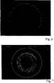
- FIG. 6 shows a high contrast image of a contact lens that has been dried in accordance with a prior art nozzle
- Fig. 7 shows an image of a contact lens that has been dried using a nozzle as it has been described above in accordance with the present invention.
Landscapes
- Engineering & Computer Science (AREA)
- Mechanical Engineering (AREA)
- General Engineering & Computer Science (AREA)
- Health & Medical Sciences (AREA)
- Manufacturing & Machinery (AREA)
- Ophthalmology & Optometry (AREA)
- Drying Of Solid Materials (AREA)
- Eyeglasses (AREA)
- Nozzles (AREA)
Description
- The present invention relates to a drying nozzle for drying a peripheral portion of an ophthalmic lens, in particular a contact lens.
- In the production of contact lenses the lenses are typically automatically inspected for defects in the optical zone as well as in the peripheral portion of the lens, since the peripheral portion and in particular the lens edge greatly affects the wearing comfort that is experienced by the user. Contact lenses which are defective either in the optical zone or in the peripheral portion are rejected, at least if predetermined threshold values for identifying such defects are exceeded.
- In a known mass production process of contact lenses a viscous starting material is dispensed into a female mold half, the mold is then closed with the aid of the male mold half, and the starting material in the mold is then exposed to UV-light, so that the starting material between the shaping surfaces of the male and female mold halves is crosslinked and/or polymerized to form the contact lens. Subsequently, the mold is opened and the lens so formed is loosened from the mold half to which it sticks by the application of water. Also, the water serves to wash away any excess starting material which has not been crosslinked and/or polymerized. The wet contact lens is then gripped and later in the process the peripheral portion of the lens, in particular the edge of the lens, is automatically inspected. Typically this is done with the aid of image analysis, which itself makes use of a high contrast image (dark background, bright representation of the lens edge).
- However, due to the fact that the contact lens the edge of which is to be inspected is still wet (e.g. water droplets adhere to the lens), the automatic inspection system may detect a lens as being defective although it is not. The water droplets cause the lens edge to appear darker in a portion of the lens edge where a small water droplet adheres than in a portion where no such water droplet is present. Since dark portions at the lens edge are interpreted as representing a defect of the lens edge, the lens may be rejected although the lens edge indeed is not defective, thus unnecessarily increasing the reject rate. Previous attempts have been made to improve this misinterpretation by drying the contact lens by means of application of pressurized air with the aid of nozzles having discrete openings, however, this has still resulted in portions at the lens edge which are represented darker so that lenses have been rejected as being defective although they are not.
- Accordingly, it is an object to overcome these drawbacks and to provide suitable measures to decrease the number of contact lenses which are rejected as being defective at their lens edge although indeed they are not.
- In accordance with the present invention, this object is achieved by a drying nozzle as it is specified in
independent claim 1. Further embodiments of the drying nozzle according to the invention are the subject of the dependent claims. Also, a process according to claim 6 for the inspection of the peripheral portion of the lens, in particular of the lens edge, is suggested, which uses the drying nozzle according to the invention. - In particular, the drying nozzle for drying a peripheral portion of an ophthalmic lens, in particular a contact lens, comprises an inlet for the supply of a pressurized gas, in particular pressurized air, and a continuous annular outlet gap having a predetermined width. Through the continuous annular outlet gap the pressurized air is capable of being supplied to the peripheral portion of the ophthalmic lens. The continuous annular outlet gap provides for an even distribution of the pressurized air impacting on the lens to be dried and thus reliably and evenly dries the lens in its peripheral portion and in particular at the lens edge, so that the lens edge is represented evenly bright in the high contrast image, so that darker portions of the lens edge are indeed caused by defective portions of the lens edge (e.g. by small tears). Accordingly, unjustified lens rejections due to water droplets or the like can be greatly reduced or even completely avoided, thus reducing the overall rejection rate and increasing the performance of the production process.
- In one embodiment of the drying nozzle according to the invention, the width of the continuous annular outlet gap is in the range of 0.2 mm to 0.8 mm, more particularly in the range of 0.4 mm to 0.6 mm, and in particular is about 0.5 mm. These ranges or values, respectively, for the width of the continuous annular outlet gap are suitable for achieving the desired effect.
- According to the invention, the nozzle comprises a body and a cap which can be screwed onto the nozzle body in a manner such, that the continuous annular outlet gap is formed between the cap and the body when the cap is screwed onto the body. The body comprises the inlet for the supply of pressurized gas and at least one feed channel extending from the inlet to a plurality of distribution channels, which are arranged to connect the feed channel with the continuous annular outlet gap. This is a particularly advantageous two-part nozzle construction which can easily be assembled and disassembled, as this may be desirable for example to clean the nozzle parts from time to time.
- In still a further embodiment of the drying nozzle according to the invention the body and the cap are provided with means for centering the cap on the body upon screwing the cap onto the body. This facilitates screwing and unscrewing of the cap to and from the body in the correct relative orientation.
- In yet a further embodiment of the drying nozzle according to the invention, the body is provided at its inlet and along at least a part of the feed channel with an internal thread for connecting a supply duct to the body. This allows to easily and reliably connect and disconnect a supply duct to the body of the nozzle.
- Further, according to the invention, the body comprises a central bore extending axially through the upper surface of the body, and the upper surface of the body is generally concave and converges towards an outlet opening of the central bore. This embodiment is advantageous as it improves cleanliness of the upper surface of the drying nozzle: in case any liquid or dirt adheres to the upper surface, due to the concave shape such liquid or dirt is transported towards the outlet opening of the central bore from where it is blown away by pressurized air exiting through the outlet opening of the central bore.
- In still a further embodiment of the drying nozzle according to the invention, the nozzle or the nozzle parts, respectively, are made from a non-corrosive material. This is particularly a requirement in the manufacture of contact lenses, since they are sensitive articles which must be produced under strictly clean conditions.
- A further aspect of the present invention relates to a process for the inspection of the peripheral region of an ophthalmic lens, in particular for the inspection of the edge of a conctact lens according to claim 6. For arranging the lens to be dried at a predetermined distance from the continuous annular outlet gap, a suitable gripper can be used which grips the lens in the central portion of the lens (e.g. by application of suction) so that the lens edge projects outwardly beyond the gripper so that it may be inspected.
- As already mentioned above, in one variant of the process according to the invention the pressurized gas is air. The pressurized air may be applied to the lens through the continuous annular outlet gap with an (over-)pressure in the range of 0.8 to 1.2 bar.
- Further aspects of the drying nozzle or of the process according to the invention will become apparent from the following description of an embodiment of the invention with the aid of the drawings in which:
- Fig. 1
- shows a sectional view of the cap of one embodiment of the drying nozzle according to the invention,
- Fig. 2
- shows a sectional view of the body of the embodiment of the drying nozzle which is not part of the invention, the cap of which is shown in
Fig. 1 , - Fig. 3
- shows in a partial sectional view the embodiment of the drying nozzle with the cap of
Fig. 1 and the body ofFig. 2 in an assembled state, - Fig. 4
- shows a side view of an embodiment of a gripper suitable for holding a contact lens to be dried, with the drying nozzle being arranged at a predetermined distance from the gripper,
- Fig. 5
- shows a bottom view of the gripper of
Fig. 4 for carrying the contact lens, - Fig. 6
- shows a high contrast image of a contact lens which has been dried in accordance with a prior art nozzle,
- Fig. 7
- shows a high contrast image of a contact lens which has been dried in accordance with a nozzle according to the present invention, and
- Fig. 8
- shows a (greatly enlarged) sectional view of the body of the drying nozzle according to the invention.
- An embodiment of the
drying nozzle 1 is shown inFigs. 1-3 , withFig. 1 showing only thecap 2 of the nozzle,Fig. 2 showing only thebody 3 of the nozzle, andFig. 3 showing thenozzle 1 comprising both thecap 2 and thebody 3 in the assembled state. - The
cap 2 comprises a centrally arrangedcylindrical bore 20 having portions with different inner diameters. One of these portions is provided with aninternal thread 200 allowing to screwcap 2 ontobody 3.Body 3 is provided with a corresponding external thread onbody 3, accordingly.Cylindrical bore 20 further comprises afitting portion 21 having an inner diameter which corresponds to the outer diameter of a corresponding fitting portion ofbody 3 in order to cause thecap 2 to get centered during screwing ofcap 2 ontobody 3. -
Body 3 has aninlet 30 and afeed channel 31 defined by a cylindrical bore. Feedchannel 31 is at least partly provided with aninternal thread 310 allowing to connect a supply duct (not shown) to thebody 3 ofnozzle 1 by means of a screw connection. From the end remote frominlet 30 a plurality ofdistribution channels 311 extend radially outwardly fromfeed channel 31. -
Body 3 is further provided with a cylindrical portion that is provided on its outer surface with anexternal thread 312 for engagement with theinternal thread 200 ofcap 2 when screwingcap 2 ontobody 3. Yet further,body 3 comprises afitting portion 32 having an outer diameter corresponding to the inner diameter offitting portion 21 ofcap 2 so as to cause the cap to get centered upon screwingcap 2 ontobody 3. - Once
cap 2 has been screwed onto body 3 (seeFig. 3 ), theexternal thread 312 ofbody 3 is in engagement with theinternal thread 200 ofcap 2, and thefitting portions cap 2 is centered onbody 3. At the radial outer ends of thedistribution channels 311 asmall gap 10 extends towards the upper end of thenozzle 1, where a continuousannular outlet gap 11 is formed betweencap 2 andbody 3. The continuousannular outlet gap 11 has a width W which is in the range of 0.2 mm to 0.8 mm, more particularly in the range of 0.4 mm to 0.6 mm, and in particular has a width of about 0.5 mm. - As pressurized air is entering
feed channel 31 through a supply duct (not shown) which is screwed in throughinlet 30 to engageinternal thread 310 offeed channel 31, the pressurized air is distributed radially outwardly through thedistribution channels 311 into thesmall gap 10, and is subsequently supplied evenly distributed through continuousannular outlet gap 11. - The
nozzle 1 or the nozzle parts, that is to saycap 2 andbody 3, are made from a non-corrosive material, for example from anodized aluminum, and preferably can be easily cleaned by unscrewingcap 2 frombody 3 and cleaning the individual parts. - The body 3a of the drying nozzle according to the invention is shown greatly enlarged in
Fig. 8 . While this embodiment largely corresponds to the embodiment ofbody 3 shown inFig. 2 , there are certain differences which will be explained below. Again, body 3a has aninlet 30a and afeed channel 31 a defined by a cylindrical bore. While not being shown inFig. 8 ,feed channel 31 a may again be provided with an internal thread allowing to connect a supply duct (not shown) to body 3a by means of a screw connection. From the end remote frominlet 30a a plurality ofdistribution channels 311 a (only two of them being shown inFig. 8 ) extend radially outwardly fromfeed channel 31 a. However, in addition to the radially outwardly extendingdistribution channels 311 a body 3a has acentral bore 313a extending axially and having its outlet atupper surface 314a of body 3a. By way of example,central bore 313a may have a diameter between 1 mm and 2 mm and may in particular have a diameter of about 1.6 mm.Upper surface 314a has a generally concave shape (e.g. a conical shape including an angle in the range of between 4° and 5° with the horizontal) converging towards the outlet ofcentral bore 313a. These measures serve to reduce or to eliminate any liquid and/or dirt to accumulate onupper surface 314a. In case there is any liquid or dirt adhering toupper surface 314a, due to the concave shape ofupper surface 314a such liquid (e.g. droplets) or dirt is urged towards the outlet ofcetnral bore 313a. The pressurized air exiting through the outlet ofcentral bore 314a then blows away this liquid and/or dirt, thus further improving the cleanliness of the nozzle according to the invention. Similar to the embodiment shown inFig. 2 , body 3a ofFig. 8 is further provided with acylindrical portion 312a which may be provided on its outer surface with an external thread (similar toFig. 2 , but not shown inFig. 8 ) for engagement with the internal thread of the cap when screwing the cap onto body 3a. For further details it is referred to the description of the embodiment shown inFig. 2 above. - From
Fig. 4 and Fig. 5 the dryingnozzle 1 can be seen in a process of inspecting the peripheral portion of a contact lens which is represented inFig. 5 through dashed lines CL, in particular of the lens edge. The step of inspection itself is not represented in the drawings, since it is well-known in the art (e.g. production of a high contrast image). Rather, the step of drying of the contact lens with the aid of dryingnozzle 1 as described above is shown, since the wet contact lens is to be dried prior to inspection. For presenting the contact lens CL to be dried tonozzle 1, agripper 4 is provided having a convexdistal end surface 40 which is provided withholes 41 through which suction may be applied so as to make the contact lens CL stick to endsurface 40 ofgripper 4 in a central portion of the lens. - As can be seen best in
Fig. 4 , dryingnozzle 1 is arranged at a predetermined distance D from the continuous annular outlet gap of dryingnozzle 1. This distance D may be in the range of 2 mm to 5 mm, and may in particular be about 3 mm. In the bottom view of thegripper 4 for carrying the contact lens, the outer boundary of a virtually present contact lens CL is indicated by dashed lines. For the sake of clarity, the outer diameter of continuousannular outlet gap 11 ofnozzle 1 is also indicated by dashed lines. As pressurized air having a pressure in the range of e.g. 0.8 bar to 1.2 bar is supplied and impacts the contact lens CL through theannular outlet gap 11 ofnozzle 1, contact lens CL is evenly dried in its peripheral portion and in particular at its lens edge. After that, no more water droplets are adhering there to the contact lens, so that a brightly illuminated contact lens edge can be seen in the high contrast image during inspection (assuming that the lens has no edge defects). - Since suction is applied only in the central portion of the contact lens CL, the lens does only stick to the
end surface 40 ofgripper 4 in its central portion, that is to say the peripheral portion of the lens and in particular the lens edge does not stick to theend surface 40 ofgripper 4, so that it is possible to obtain a clear high contrast image of the lens edge. - As mentioned above, when using the nozzle according to the instant invention any unjustified lens rejections due to water droplets or the like can be greatly reduced or even completely avoided, thus reducing the overall rejection rate and increasing the performance of the production process.
- This becomes particularly evident when glancing at the high contrast images of a contact lens shown in
Fig. 6 and inFig. 7 , withFig. 6 showing a high contrast image of a contact lens that has been dried in accordance with a prior art nozzle whileFig. 7 shows an image of a contact lens that has been dried using a nozzle as it has been described above in accordance with the present invention. - While the invention has been described with the aid of specific embodiments, alternative embodiments are conceivable as well without departing from the teaching of the present invention. Accordingly, such embodiments are believed to be within the scope of protection of the present invention, which is not intended to be limited to the specific embodiments described, but rather is defined through the appended claims.
Claims (14)
- Drying nozzle (1) for drying a peripheral portion of a contact lens, comprising an inlet (30a) for the supply of a pressurized gas, wherein the nozzle comprises a continuous annular outlet gap (11) having a predetermined width (W) through which the pressurized gas is capable of being supplied to the peripheral portion of the contact lens (CL), the nozzle comprising a body (3a) and a cap (2) which can be screwed onto the nozzle body (3a) in a manner such, that the continuous annular outlet gap (11) is formed between the cap (2) and the body (3a) when the cap (2) is screwed onto the body (3a), the body (3a) comprising the inlet (30a) for the supply of pressurized gas and at least one feed channel (31a) extending from the inlet (30a) to a plurality of distribution channels (311a), which are arranged to connect the feed channel (31a) with the continuous annular outlet gap (11), the body (3a) further comprising a central bore (313a) extending axially through the upper surface (314a) of the body (3a), characterized in that the upper surface (314a) of the body is generally concave and converges towards the outlet opening of the central bore (313a).
- Drying nozzle (1) according to claim 1, wherein the width (W) of the continuous annular outlet gap (11) is in the range of 0.2 mm to 0.8 mm, more particularly in the range of 0.4 mm to 0.6 mm, and in particular is about 0.5 mm.
- Drying nozzle according to claim 1 or claim 2, wherein the body (3a) and the cap (2) are provided with means (32,21) for centering the cap (2) on the body (3a) upon screwing the cap (2) onto the body (3a).
- Drying nozzle according to anyone of the preceding claims, wherein the body (3a) is provided at its inlet (30a) and along at least a part of the feed channel (31a) with an internal thread (310) for connecting a supply duct to the body (3a).
- Drying nozzle according to any one of the preceding claims, wherein the nozzle (1) or the nozzle parts (2, 3a), respectively, are made from a non-corrosive material.
- Process for the inspection of the peripheral region of a contact lens (CL), in particular for the inspection of the edge of a contact lens, comprising the steps of drying the peripheral area of a wet contact lens to be inspected by exposing it to pressurized gas, and subsequently automatically inspecting the peripheral area of the contact lens (CL) with the aid of image analysis, wherein the step of exposing the peripheral area of the wet contact lens to pressurized gas is performed by using a drying nozzle (1), wherein the drying nozzle (1) comprises an inlet (30;30a) for the supply of a pressurized gas, characterized in that the drying nozzle (1) comprises a continuous annular outer gap (11) having a predetermined width (W) through which the pressurized gas is capable of being supplied to the peripheral portion of the wet contact lens (CL), and by arranging the wet contact lens (CL) at a predetermined distance from the continuous annular outlet gap (11) of the nozzle (1).
- Process according to claim 6, wherein the width (W) of the continuous annular outlet gap (11) is in the range of 0.2 mm to 0.8 mm, more particularly in the range of 0.4 mm to 0.6 mm, and in particular is about 6.5 mm.
- Process according to claim 6 or claim 7, wherein the nozzle comprises a body (3;3a) and a cap (2) which can be screwed onto the nozzle body (3;3a) in a manner such, that the continuous annular outlet gap (11) is formed between the cap (2) and the body (3;3a) when the cap (2) is screwed onto the body (3;3a), the body (3;3a) comprising the inlet (30;30a) for the supply of pressurized gas, at least one feed channel (31;31 a) extending from the inlet (30;30a) to a plurality of distribution channels (311 ;311 a), which are arranged to connect the feed channel (31 ;31a) with the continuous annular outlet gap (11).
- Process according to claim 8, wherein the body (3;3a) and the cap (2) are provided with means (32,21) for centering the cap (2) on the body (3;3a) upon screwing the cap (2) onto the body (3;3a).
- Process according to claim 8 or claim 9, wherein the body (3;3a) is provided at its inlet (30;30a) and along at least a part of the feed channel (31;31 a) with an internal thread (310) for connecting a supply duct to the body (3;3a).
- Process according to anyone of claims 8 to 10, wherein the body (3a) comprises a central bore (313a) extending axially through the upper surface (314a) of the body (3a), and wherein the upper surface (314a) of the body is generally concave and converges towards an outlet opening of the central bore (313a).
- Process according to anyone of claims 6 to 11, wherein the nozzle (1) or the nozzle parts (2,3,3a), respectively, are made from a non-corrosive material.
- Process according to anyone of claims 6 to 12, wherein the pressurized gas is air.
- Process according to claim 13, wherein the pressure of the air is in the range of 0.8 to 1.2 bar.
Priority Applications (1)
| Application Number | Priority Date | Filing Date | Title |
|---|---|---|---|
| EP09757555.9A EP2293926B1 (en) | 2008-06-06 | 2009-06-03 | Drying nozzle and method of drying |
Applications Claiming Priority (3)
| Application Number | Priority Date | Filing Date | Title |
|---|---|---|---|
| EP08157781 | 2008-06-06 | ||
| PCT/EP2009/056819 WO2009147174A1 (en) | 2008-06-06 | 2009-06-03 | Drying nozzle |
| EP09757555.9A EP2293926B1 (en) | 2008-06-06 | 2009-06-03 | Drying nozzle and method of drying |
Publications (2)
| Publication Number | Publication Date |
|---|---|
| EP2293926A1 EP2293926A1 (en) | 2011-03-16 |
| EP2293926B1 true EP2293926B1 (en) | 2016-05-04 |
Family
ID=39876686
Family Applications (1)
| Application Number | Title | Priority Date | Filing Date |
|---|---|---|---|
| EP09757555.9A Active EP2293926B1 (en) | 2008-06-06 | 2009-06-03 | Drying nozzle and method of drying |
Country Status (6)
| Country | Link |
|---|---|
| US (1) | US8115917B2 (en) |
| EP (1) | EP2293926B1 (en) |
| CN (1) | CN102056732B (en) |
| HU (1) | HUE028149T2 (en) |
| MY (1) | MY152415A (en) |
| WO (1) | WO2009147174A1 (en) |
Family Cites Families (2)
| Publication number | Priority date | Publication date | Assignee | Title |
|---|---|---|---|---|
| ATE26546T1 (en) * | 1981-11-18 | 1987-05-15 | Hans Moss | BLOW NOZZLE FOR SILENT GAS FLOW. |
| DE20106262U1 (en) * | 2001-04-10 | 2002-08-22 | Novartis Ag, Basel | blow nozzle |
-
2009
- 2009-06-03 US US12/477,164 patent/US8115917B2/en active Active
- 2009-06-03 EP EP09757555.9A patent/EP2293926B1/en active Active
- 2009-06-03 WO PCT/EP2009/056819 patent/WO2009147174A1/en not_active Ceased
- 2009-06-03 MY MYPI20105167 patent/MY152415A/en unknown
- 2009-06-03 CN CN200980120923.8A patent/CN102056732B/en active Active
- 2009-06-03 HU HUE09757555A patent/HUE028149T2/en unknown
Also Published As
| Publication number | Publication date |
|---|---|
| CN102056732B (en) | 2014-06-25 |
| EP2293926A1 (en) | 2011-03-16 |
| US8115917B2 (en) | 2012-02-14 |
| WO2009147174A1 (en) | 2009-12-10 |
| HUE028149T2 (en) | 2016-12-28 |
| CN102056732A (en) | 2011-05-11 |
| MY152415A (en) | 2014-09-30 |
| US20090310129A1 (en) | 2009-12-17 |
Similar Documents
| Publication | Publication Date | Title |
|---|---|---|
| EP2254798B1 (en) | Method and apparatus for inverting a flexible molding | |
| CN101563213A (en) | Apparatus and method for releasing a lens moulded in a cavity between posterior and anterior mould sections | |
| US20250321195A1 (en) | Method and apparatus for optically checking molded parts | |
| AU770636B2 (en) | Method and apparatus for vacuum assisted venting | |
| US7660051B2 (en) | Optical lens base with protective film and process for producing optical lens base | |
| US8115917B2 (en) | Drying nozzle | |
| US20160339654A1 (en) | Method and mold for fabricating contact lens and controlling excess material and method for fabricating the same mold | |
| KR200463834Y1 (en) | Glass bottle loading instrument of chain spindle conveyor for paintng the surface of glass bottle | |
| EP3927221B1 (en) | Rotating injection propeller with 2k-seal | |
| CN115456652A (en) | Tracing method for defective products of precision injection molding parts based on artificial intelligence | |
| FI117621B (en) | Procedure for producing a workpiece and a workpiece | |
| JP5515699B2 (en) | Nozzle drying nozzle for oil well pipe | |
| CN104233490B (en) | Stripped thread baffle plate and lateral-blowing air cooling device | |
| CN107639717A (en) | A kind of washbasin production method | |
| KR102585242B1 (en) | Apparatus for Aluminum Extrusion Molding and Extrusion Molding Method Thereof | |
| US6681498B2 (en) | Blast nozzle | |
| CN216688428U (en) | Melt-blown mould | |
| CN209151791U (en) | A kind of adjustable markingoff pin film-spreading roller | |
| US20050056955A1 (en) | Demolding process | |
| KR200350987Y1 (en) | Do silicone balance application cap blow molding a device | |
| EP3389971B1 (en) | Preform provided with a concave body portion | |
| CN105709383A (en) | Golf club protective coating | |
| CN216800736U (en) | Cleaning device for finger melting instrument | |
| KR960015312B1 (en) | Neck tube cleaning device and method | |
| US6939118B2 (en) | Molding apparatus for toric contact lenses |
Legal Events
| Date | Code | Title | Description |
|---|---|---|---|
| PUAI | Public reference made under article 153(3) epc to a published international application that has entered the european phase |
Free format text: ORIGINAL CODE: 0009012 |
|
| 17P | Request for examination filed |
Effective date: 20101229 |
|
| AK | Designated contracting states |
Kind code of ref document: A1 Designated state(s): AT BE BG CH CY CZ DE DK EE ES FI FR GB GR HR HU IE IS IT LI LT LU LV MC MK MT NL NO PL PT RO SE SI SK TR |
|
| AX | Request for extension of the european patent |
Extension state: AL BA RS |
|
| DAX | Request for extension of the european patent (deleted) | ||
| 17Q | First examination report despatched |
Effective date: 20150330 |
|
| GRAP | Despatch of communication of intention to grant a patent |
Free format text: ORIGINAL CODE: EPIDOSNIGR1 |
|
| INTG | Intention to grant announced |
Effective date: 20151208 |
|
| GRAS | Grant fee paid |
Free format text: ORIGINAL CODE: EPIDOSNIGR3 |
|
| GRAA | (expected) grant |
Free format text: ORIGINAL CODE: 0009210 |
|
| AK | Designated contracting states |
Kind code of ref document: B1 Designated state(s): AT BE BG CH CY CZ DE DK EE ES FI FR GB GR HR HU IE IS IT LI LT LU LV MC MK MT NL NO PL PT RO SE SI SK TR |
|
| REG | Reference to a national code |
Ref country code: GB Ref legal event code: FG4D |
|
| REG | Reference to a national code |
Ref country code: CH Ref legal event code: EP |
|
| REG | Reference to a national code |
Ref country code: AT Ref legal event code: REF Ref document number: 796521 Country of ref document: AT Kind code of ref document: T Effective date: 20160515 |
|
| REG | Reference to a national code |
Ref country code: IE Ref legal event code: FG4D |
|
| REG | Reference to a national code |
Ref country code: DE Ref legal event code: R096 Ref document number: 602009038410 Country of ref document: DE |
|
| REG | Reference to a national code |
Ref country code: NL Ref legal event code: MP Effective date: 20160504 |
|
| REG | Reference to a national code |
Ref country code: LT Ref legal event code: MG4D |
|
| PG25 | Lapsed in a contracting state [announced via postgrant information from national office to epo] |
Ref country code: NO Free format text: LAPSE BECAUSE OF FAILURE TO SUBMIT A TRANSLATION OF THE DESCRIPTION OR TO PAY THE FEE WITHIN THE PRESCRIBED TIME-LIMIT Effective date: 20160804 Ref country code: LT Free format text: LAPSE BECAUSE OF FAILURE TO SUBMIT A TRANSLATION OF THE DESCRIPTION OR TO PAY THE FEE WITHIN THE PRESCRIBED TIME-LIMIT Effective date: 20160504 Ref country code: NL Free format text: LAPSE BECAUSE OF FAILURE TO SUBMIT A TRANSLATION OF THE DESCRIPTION OR TO PAY THE FEE WITHIN THE PRESCRIBED TIME-LIMIT Effective date: 20160504 Ref country code: FI Free format text: LAPSE BECAUSE OF FAILURE TO SUBMIT A TRANSLATION OF THE DESCRIPTION OR TO PAY THE FEE WITHIN THE PRESCRIBED TIME-LIMIT Effective date: 20160504 |
|
| REG | Reference to a national code |
Ref country code: AT Ref legal event code: MK05 Ref document number: 796521 Country of ref document: AT Kind code of ref document: T Effective date: 20160504 |
|
| PG25 | Lapsed in a contracting state [announced via postgrant information from national office to epo] |
Ref country code: LV Free format text: LAPSE BECAUSE OF FAILURE TO SUBMIT A TRANSLATION OF THE DESCRIPTION OR TO PAY THE FEE WITHIN THE PRESCRIBED TIME-LIMIT Effective date: 20160504 Ref country code: SE Free format text: LAPSE BECAUSE OF FAILURE TO SUBMIT A TRANSLATION OF THE DESCRIPTION OR TO PAY THE FEE WITHIN THE PRESCRIBED TIME-LIMIT Effective date: 20160504 Ref country code: PT Free format text: LAPSE BECAUSE OF FAILURE TO SUBMIT A TRANSLATION OF THE DESCRIPTION OR TO PAY THE FEE WITHIN THE PRESCRIBED TIME-LIMIT Effective date: 20160905 Ref country code: HR Free format text: LAPSE BECAUSE OF FAILURE TO SUBMIT A TRANSLATION OF THE DESCRIPTION OR TO PAY THE FEE WITHIN THE PRESCRIBED TIME-LIMIT Effective date: 20160504 Ref country code: ES Free format text: LAPSE BECAUSE OF FAILURE TO SUBMIT A TRANSLATION OF THE DESCRIPTION OR TO PAY THE FEE WITHIN THE PRESCRIBED TIME-LIMIT Effective date: 20160504 Ref country code: GR Free format text: LAPSE BECAUSE OF FAILURE TO SUBMIT A TRANSLATION OF THE DESCRIPTION OR TO PAY THE FEE WITHIN THE PRESCRIBED TIME-LIMIT Effective date: 20160805 |
|
| REG | Reference to a national code |
Ref country code: HU Ref legal event code: AG4A Ref document number: E028149 Country of ref document: HU |
|
| PG25 | Lapsed in a contracting state [announced via postgrant information from national office to epo] |
Ref country code: IT Free format text: LAPSE BECAUSE OF FAILURE TO SUBMIT A TRANSLATION OF THE DESCRIPTION OR TO PAY THE FEE WITHIN THE PRESCRIBED TIME-LIMIT Effective date: 20160504 Ref country code: BE Free format text: LAPSE BECAUSE OF NON-PAYMENT OF DUE FEES Effective date: 20160630 |
|
| PG25 | Lapsed in a contracting state [announced via postgrant information from national office to epo] |
Ref country code: DK Free format text: LAPSE BECAUSE OF FAILURE TO SUBMIT A TRANSLATION OF THE DESCRIPTION OR TO PAY THE FEE WITHIN THE PRESCRIBED TIME-LIMIT Effective date: 20160504 Ref country code: RO Free format text: LAPSE BECAUSE OF FAILURE TO SUBMIT A TRANSLATION OF THE DESCRIPTION OR TO PAY THE FEE WITHIN THE PRESCRIBED TIME-LIMIT Effective date: 20160504 Ref country code: SK Free format text: LAPSE BECAUSE OF FAILURE TO SUBMIT A TRANSLATION OF THE DESCRIPTION OR TO PAY THE FEE WITHIN THE PRESCRIBED TIME-LIMIT Effective date: 20160504 Ref country code: EE Free format text: LAPSE BECAUSE OF FAILURE TO SUBMIT A TRANSLATION OF THE DESCRIPTION OR TO PAY THE FEE WITHIN THE PRESCRIBED TIME-LIMIT Effective date: 20160504 Ref country code: CZ Free format text: LAPSE BECAUSE OF FAILURE TO SUBMIT A TRANSLATION OF THE DESCRIPTION OR TO PAY THE FEE WITHIN THE PRESCRIBED TIME-LIMIT Effective date: 20160504 |
|
| REG | Reference to a national code |
Ref country code: CH Ref legal event code: PL |
|
| REG | Reference to a national code |
Ref country code: DE Ref legal event code: R097 Ref document number: 602009038410 Country of ref document: DE |
|
| PG25 | Lapsed in a contracting state [announced via postgrant information from national office to epo] |
Ref country code: BE Free format text: LAPSE BECAUSE OF FAILURE TO SUBMIT A TRANSLATION OF THE DESCRIPTION OR TO PAY THE FEE WITHIN THE PRESCRIBED TIME-LIMIT Effective date: 20160504 Ref country code: PL Free format text: LAPSE BECAUSE OF FAILURE TO SUBMIT A TRANSLATION OF THE DESCRIPTION OR TO PAY THE FEE WITHIN THE PRESCRIBED TIME-LIMIT Effective date: 20160504 Ref country code: AT Free format text: LAPSE BECAUSE OF FAILURE TO SUBMIT A TRANSLATION OF THE DESCRIPTION OR TO PAY THE FEE WITHIN THE PRESCRIBED TIME-LIMIT Effective date: 20160504 |
|
| PLBE | No opposition filed within time limit |
Free format text: ORIGINAL CODE: 0009261 |
|
| STAA | Information on the status of an ep patent application or granted ep patent |
Free format text: STATUS: NO OPPOSITION FILED WITHIN TIME LIMIT |
|
| PG25 | Lapsed in a contracting state [announced via postgrant information from national office to epo] |
Ref country code: MC Free format text: LAPSE BECAUSE OF FAILURE TO SUBMIT A TRANSLATION OF THE DESCRIPTION OR TO PAY THE FEE WITHIN THE PRESCRIBED TIME-LIMIT Effective date: 20160504 |
|
| REG | Reference to a national code |
Ref country code: FR Ref legal event code: ST Effective date: 20170228 |
|
| 26N | No opposition filed |
Effective date: 20170207 |
|
| PG25 | Lapsed in a contracting state [announced via postgrant information from national office to epo] |
Ref country code: CH Free format text: LAPSE BECAUSE OF NON-PAYMENT OF DUE FEES Effective date: 20160630 Ref country code: FR Free format text: LAPSE BECAUSE OF NON-PAYMENT OF DUE FEES Effective date: 20160704 Ref country code: LI Free format text: LAPSE BECAUSE OF NON-PAYMENT OF DUE FEES Effective date: 20160630 |
|
| PG25 | Lapsed in a contracting state [announced via postgrant information from national office to epo] |
Ref country code: SI Free format text: LAPSE BECAUSE OF FAILURE TO SUBMIT A TRANSLATION OF THE DESCRIPTION OR TO PAY THE FEE WITHIN THE PRESCRIBED TIME-LIMIT Effective date: 20160504 |
|
| PG25 | Lapsed in a contracting state [announced via postgrant information from national office to epo] |
Ref country code: CY Free format text: LAPSE BECAUSE OF FAILURE TO SUBMIT A TRANSLATION OF THE DESCRIPTION OR TO PAY THE FEE WITHIN THE PRESCRIBED TIME-LIMIT Effective date: 20160504 |
|
| PG25 | Lapsed in a contracting state [announced via postgrant information from national office to epo] |
Ref country code: MT Free format text: LAPSE BECAUSE OF NON-PAYMENT OF DUE FEES Effective date: 20160630 Ref country code: LU Free format text: LAPSE BECAUSE OF NON-PAYMENT OF DUE FEES Effective date: 20160603 Ref country code: IS Free format text: LAPSE BECAUSE OF FAILURE TO SUBMIT A TRANSLATION OF THE DESCRIPTION OR TO PAY THE FEE WITHIN THE PRESCRIBED TIME-LIMIT Effective date: 20160504 Ref country code: MK Free format text: LAPSE BECAUSE OF FAILURE TO SUBMIT A TRANSLATION OF THE DESCRIPTION OR TO PAY THE FEE WITHIN THE PRESCRIBED TIME-LIMIT Effective date: 20160504 Ref country code: TR Free format text: LAPSE BECAUSE OF FAILURE TO SUBMIT A TRANSLATION OF THE DESCRIPTION OR TO PAY THE FEE WITHIN THE PRESCRIBED TIME-LIMIT Effective date: 20160504 |
|
| PG25 | Lapsed in a contracting state [announced via postgrant information from national office to epo] |
Ref country code: BG Free format text: LAPSE BECAUSE OF FAILURE TO SUBMIT A TRANSLATION OF THE DESCRIPTION OR TO PAY THE FEE WITHIN THE PRESCRIBED TIME-LIMIT Effective date: 20160504 |
|
| REG | Reference to a national code |
Ref country code: HU Ref legal event code: GB9C Owner name: ALCON INC., CH Free format text: FORMER OWNER(S): NOVARTIS AG, CH |
|
| REG | Reference to a national code |
Ref country code: DE Ref legal event code: R081 Ref document number: 602009038410 Country of ref document: DE Owner name: ALCON INC., CH Free format text: FORMER OWNER: NOVARTIS AG, 4056 BASEL, CH |
|
| REG | Reference to a national code |
Ref country code: GB Ref legal event code: 732E Free format text: REGISTERED BETWEEN 20200123 AND 20200129 |
|
| P01 | Opt-out of the competence of the unified patent court (upc) registered |
Effective date: 20230504 |
|
| PGFP | Annual fee paid to national office [announced via postgrant information from national office to epo] |
Ref country code: DE Payment date: 20250521 Year of fee payment: 17 |
|
| PGFP | Annual fee paid to national office [announced via postgrant information from national office to epo] |
Ref country code: GB Payment date: 20250522 Year of fee payment: 17 |
|
| PGFP | Annual fee paid to national office [announced via postgrant information from national office to epo] |
Ref country code: IE Payment date: 20250523 Year of fee payment: 17 |
|
| PGFP | Annual fee paid to national office [announced via postgrant information from national office to epo] |
Ref country code: HU Payment date: 20250610 Year of fee payment: 17 |