EP2293731B1 - Device and a system for displacing bones - Google Patents
Device and a system for displacing bones Download PDFInfo
- Publication number
- EP2293731B1 EP2293731B1 EP09755134.5A EP09755134A EP2293731B1 EP 2293731 B1 EP2293731 B1 EP 2293731B1 EP 09755134 A EP09755134 A EP 09755134A EP 2293731 B1 EP2293731 B1 EP 2293731B1
- Authority
- EP
- European Patent Office
- Prior art keywords
- engagement
- support
- vertebrae
- support part
- implant
- Prior art date
- Legal status (The legal status is an assumption and is not a legal conclusion. Google has not performed a legal analysis and makes no representation as to the accuracy of the status listed.)
- Not-in-force
Links
Images
Classifications
-
- A—HUMAN NECESSITIES
- A61—MEDICAL OR VETERINARY SCIENCE; HYGIENE
- A61B—DIAGNOSIS; SURGERY; IDENTIFICATION
- A61B17/00—Surgical instruments, devices or methods
- A61B17/56—Surgical instruments or methods for treatment of bones or joints; Devices specially adapted therefor
- A61B17/58—Surgical instruments or methods for treatment of bones or joints; Devices specially adapted therefor for osteosynthesis, e.g. bone plates, screws or setting implements
- A61B17/68—Internal fixation devices, including fasteners and spinal fixators, even if a part thereof projects from the skin
- A61B17/70—Spinal positioners or stabilisers, e.g. stabilisers comprising fluid filler in an implant
- A61B17/7074—Tools specially adapted for spinal fixation operations other than for bone removal or filler handling
- A61B17/7076—Tools specially adapted for spinal fixation operations other than for bone removal or filler handling for driving, positioning or assembling spinal clamps or bone anchors specially adapted for spinal fixation
- A61B17/7077—Tools specially adapted for spinal fixation operations other than for bone removal or filler handling for driving, positioning or assembling spinal clamps or bone anchors specially adapted for spinal fixation for moving bone anchors attached to vertebrae, thereby displacing the vertebrae
-
- A—HUMAN NECESSITIES
- A61—MEDICAL OR VETERINARY SCIENCE; HYGIENE
- A61B—DIAGNOSIS; SURGERY; IDENTIFICATION
- A61B17/00—Surgical instruments, devices or methods
- A61B17/56—Surgical instruments or methods for treatment of bones or joints; Devices specially adapted therefor
- A61B17/58—Surgical instruments or methods for treatment of bones or joints; Devices specially adapted therefor for osteosynthesis, e.g. bone plates, screws or setting implements
- A61B17/60—Surgical instruments or methods for treatment of bones or joints; Devices specially adapted therefor for osteosynthesis, e.g. bone plates, screws or setting implements for external osteosynthesis, e.g. distractors, contractors
- A61B17/66—Alignment, compression or distraction mechanisms
-
- A—HUMAN NECESSITIES
- A61—MEDICAL OR VETERINARY SCIENCE; HYGIENE
- A61B—DIAGNOSIS; SURGERY; IDENTIFICATION
- A61B90/00—Instruments, implements or accessories specially adapted for surgery or diagnosis and not covered by any of the groups A61B1/00 - A61B50/00, e.g. for luxation treatment or for protecting wound edges
- A61B90/39—Markers, e.g. radio-opaque or breast lesions markers
- A61B2090/3937—Visible markers
Definitions
- the invention concerns a device according to the preamble of claim 1 and a system for engagement with vertebrae in a spinal column including such a device.
- the invention also concerns a use of the device.
- WO 06130085 describes in general a positioning device and in particular a device, which is mainly used when positioning of a disc implant in combination with separating of vertebrae.
- the positioning of the disc implant results in accurate replacement of the disc that causes pain, reinstating the distance between the vertebrae and reinstating movability between them.
- WO 06130085 discloses distance means that carry engagement means for the engagement with two vertebrae at a distance from each other. Said distance means are arranged such that they are capable of changing the degree of separation of said vertebrae when the engagement means are in engagement therewith. The possibility of spanning apart the vertebrae makes it possible, i.a. to freely remove the old disc.
- the engagement means are connected to the distance means in friction joints such that the engagement means are movably fastened to the distance devices in order to avoid excess breaking forces in connection with separating vertebrae.
- WO 9002527 concerns a distractor having parallel coupled first and second adjustment means for maneuvering engagement screws. This distractor gives limited possibilities for controlling the displacement of bones and is impractical for use in a real life situation.
- US 2371519 relates to extension and reduction appartus generally but is particularly intended for use in conjuction with installation of a ambulatory splint.
- a primary object of the invention resides in the provision of a small and light weight mechanism of which may rest upon the limb of a patient while being attached to the splint parts durign the process of aligning the bone fragments.
- the arrangement for altering the angle includes an actuating unit which is maneuverable for pivotal adjustment of said angle, it is made possible on the one hand to control the device so as to increase the possibilities to manipulate the bones. It is further made possible to simply provide firm support in chosen angles for the engagement elements in respect of the distance units.
- the device according to the invention has an arrangement allowing the angle of the respective engagement means to be independently adjustable, and parallel displacement is easily achieved.
- the present invention makes it possible to choose, obtain and lock not only the separation but also the angular positions of the bones (in particular vertebrae) with respect to each other and individually with respect of the distance unit. It is thus also possible to straighten up vertebrae in respect of each other or to obtain other desired relative positioning thereof.
- the engagement elements are preferably elongated and have substantially longitudinal axes.
- the engagement elements have screw treads for uncomplicated engagement with bones.
- each support part When each support part is arranged to carry an engagement element in one mode where it is movable and in another mode where it is fixed, it is achieved that it can be engaged with a bone when in position in the device and subsequently be locked at a desired position.
- one of the support part and the support portion includes a pivotal pin which is pivotally supported by a corresponding bearing in turn being included in the other one of the support part and the support portion because of simplicity reasons.
- the engagement element is pivotal in a plane substantially parallel to or even including a straight line between two support portions on one distance unit.
- the actuating unit includes a setting element on one of the support parts and the support portion that is acting against a surface portion on the other one of the support part and the support portion.
- the setting element is one from the group: a treaded sleeve, a screw, a nut, a cam.
- the distance unit has preferably means for controlled displacement of the support units in respect of each other in order to alter the degree of separation of said bones, since this provision allows for greater separating possibilities.
- the means for controlled displacement is thereby advantageously one from the group: screw means, rack and pawl, lever mechanism, telescopic elements, pneumatic means, hydraulic means.
- the invention also concerns a system for engagement with vertebrae in a spinal column including at least one device for separating bones and a holder for a prosthesis from the group: a disc implant, a vertebral implant, said holder being adjustably fixable to e.g. an engagement element in the form of a bone screw over a specially constructed positioning arrangement, said holder preferably including a fork-shaped head for external or internal cooperation with the implant.
- the system preferably includes at least one supporting device which is fixed on said at lest one device for holding an operation point for engagement with vertebrae free from body organs.
- the system according to the invention includes, in a preferred embodiment, a positioning arrangement for an implant, wherein a positioning arm has a first portion for engagement with said distance unit and a second portion for engagement with an implant holder, and wherein the holder can be locked in a desired position. This allows secure positioning of the implant when completing the process of replacing a damaged body part.
- reference numeral 1 denotes a device for displacing bones.
- the device 1 is intended and designed for the distraction of vertebra in a spinal column, so as to allow a surgeon access to an operation point between two vertebrae.
- the vertebrae are separated so as to e.g. remove a damaged disc in the process of replacing that disc with a prosthesis in the form a disc implant. In that process it is important to be able to completely clear out the region between the vertebrae, such that no parts of the damaged disc remain.
- the device according to the invention simplifies the entire operation process which will result in a more secure and fast process.
- the device 1 is comprised of two engagement elements 2' and 2" which are positioned at a distance from each other and are carried by respective support parts 3' and 3" which in turn are supported in support portions 4' and 4" of a distance unit 5.
- the distance unit 5 is telescopic and capable of being extended such that the support portions 4' and 4" and thereby the support parts 3' and 3" and thus the engagement elements 2' and 2" are displaced in respect of each other.
- a (not shown) tube transmits hydraulic medium used for actuating the telescopic distance unit 5, said unit including a (not shown) piston-cylinder aggregate of a per se known kind.
- the engagement elements 2' and 2" each have a longitudinal axis, whereof one, A, for the engagement element 2", is shown in the Figure.
- a straight line between the two support units which are each made up by a support part and an associated support portion is indicated with L.
- the longitudinal axis A of engagement element 2" forms an angle ⁇ with said straight line L.
- the line L is a symmetrical axis of a of the telescopic distance unit 5.
- the angle ⁇ is between the longitudinal axis A of the respective engagement element 2' and 2" and a plane through L and the axis of the respective pivot pin 13' and 13" (see fig 3 ).
- the engagement elements 2' and 2" are shown having tapering portions directed downwardly in Fig. 1 , and these tapering portions are provided with threads which are intended to engage possibly pre-drilled holes in bones such as vertebrae to be manipulated.
- a first rotatable sleeve 7' which is part of an actuating unit and is used for pivoted adjustment of the angle ⁇ .
- a second sleeve 11' which is used for locking the engagement element 2' inside the support part 3'.
- the actuating unit in respect of the engagement element 2' functions such that the first sleeve 7', which has a threaded inside engagement with a treaded outside on the support part 3' (see Figs 5 and 6 ), through rotation of the first sleeve 7' will obtain an axial displacement along the support part 3' and thereby along the engagement element 2'.
- An end surface of the first sleeve 7' being directed axially and downwardly in Fig. 1 and being indicated with 9' co-operates with a cam surface 10' which is situated on the support portion 4'.
- Rotation of the second sleeve 11' is between a first mode, where the engagement element 2' is free to move axially inside the support part 3' as well as to rotate inside the support part 3', and a second mode, where the engagement element 2' is locked from axial movement and from rotation.
- a locking function can be easily accomplished for example by having an inside portion of the second sleeve 11' being inwardly conical and co-operating with a small sleeve surrounding the engagement element 2' and having a correspondingly conical upper outside surface (see Fig. 5 ).
- 12' and 12" indicate wrench engagement surfaces in the form of cut-ins so as to form planar surface portions.
- the engagement elements can of course also have other means for engagement with a wrench such as e.g. Allen key holes.
- the upper part of the first sleeve 7' is shown having a notch 8', which is intended to be engaged with a corresponding protrusion of a tool used for manipulating the device 1 as will be described below.
- a corresponding notch is present on the second sleeve 11.
- the device according to the invention is most often used in pairs, which is shown in fig 2 .
- the two devices in Fig 2 are identical for better ease of handling.
- the engagement elements 2' and 2" are screwed into two adjacent vertebrae, whereby as advantageous positions as possible can be chosen in respect of bone strength etc.
- the telescopic distance units 5 are positioned by the support parts 3' and 3" being slid over and onto the fastened engagement elements 2' and 2" such that their relative position will correspond essentially to what is shown in Figs. 2 , 7 and 10a and c.
- 60 indicates holes for the connection of hoses for hydraulic fluid.
- the piston rod 5' is pressed out from the telescopic distance unit 5 so as to obtain a separating action.
- Figs. 3 and 4 are shown more details in respect of the support unit, wherein i.a. is shown in more detail a pivot pin 13', which is part of the support portion 4', stripped from the support part 3'. 14" indicates a washer/screw combination for securing the support part 3" on a pivot pin (not shown) corresponding to the pivot pin 13' and carrying a bearing portion 15" of the support part 3".
- a pivot pin 13' which is part of the support portion 4', stripped from the support part 3'.
- 14" indicates a washer/screw combination for securing the support part 3" on a pivot pin (not shown) corresponding to the pivot pin 13' and carrying a bearing portion 15" of the support part 3".
- the cooperation between the end surface 9" and the cam surface 10" is shown in more detail.
- the support part 3' provides a distance between the pivot axis, being the axis of the pin 13', and the point of engagement between the surface 9' of the first sleeve 7' and the cam surface 10' of the support portion 4', the degree of adjustment of the angle ⁇ will be dependent on the distance between these points.
- Fig. 5a shows the support part 3' and the engagement element 2' in more detail.
- the first and second sleeves (see Fig 1 ) are removed and a treaded portion 6' is shown in its entirety.
- the treaded portion 6' co-operates with both of the first and second sleeves which thus have corresponding threads inside.
- the locking function for locking the engagement element 2' mentioned above is accomplished by having a inside portion of the second sleeve 11' being inwardly conical and co-operating with a small, interrupted sleeve 16 on the engagement element 2' and having a correspondingly conical upper outside surface. Tightening of the sleeve 11' (see Fig 5b ) will accomplish clamping of the interrupted sleeve 16 on the engagement element 2' and locking it to the support part 3'.
- Fig. 6 shows an alternative the engagement element 2' in more detail.
- This engagement element 2' is distinguished from the one shown in previous figures in that the screw point 61 is constructed differently, with a peg-shaped extension 62 and an abutment surface 63, which forms a blunt angle to a symmetry axis S through the element 2'.
- This construction makes it easier to detect when the screw (element) 2' has reached a correct position in a vertebra, since it makes it possible for the surgeon to sense when the screw has passed the front cortical part thereof, the spongy inside of the vertebra and reached the rearward cortical part thereof such that the screw will be accurately engaging the hard portions of the vertebra in front and rear portions for best reception of the load.
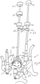
- Fig. 7 shows, diagrammatically, a system including two devices 1 for displacing two adjacent vertebrae V1 and V2 in a spinal column which is accessed through a cut C through the abdomen of a patient.
- the system is shown in an early step in the process of replacing a damaged disc in a spinal column of a human with an implant.
- the system includes an arrangement according to the invention, wherein the devices 1 have been activated so as to separate the vertebrae V1 and V2.
- the damaged disc has been removed so as to leave an empty space E between the vertebrae V1 and V2, wherein an implant is intended to be positioned.
- the two devices 1 are here shown completed with deflectors 27' and 27" that are designed to deflect sides of the cut C and body organs in the region of the operation point so as to allow better working conditions for the surgeon.
- deflectors 27' and 27" that are designed to deflect sides of the cut C and body organs in the region of the operation point so as to allow better working conditions for the surgeon.
- the spinal column is somewhat lifted in respect of the abdomen, giving the surgeon better working space and reduced depth through the cut C down to the spinal column.
- the body organs are gently removed from the operation point and securely stabilized sideways thereof.
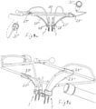
- the deflectors 27' and 27" include slightly curved panel portions and hook-like, first fastening portions, which are best shown in fig 9a and indicated with 28' and 28", for engagement with the respective distance unit 5. Further, the deflectors include, hook-like, second fastening portions 29' and 29" for the engagement with a tightening frame 30, having transversal elements for engagement with the second fastening portions 29' and 29" and longitudinal elements forming a rectangular frame 30. The transversal elements can be separated so as to obtain a down-holding and spreading effect to the deflectors 27' and 27".
- Fig. 8 shows diagrammatically a later step in the process of replacing a damaged disc.
- the system is here shown with a positioning arrangement 22 for an implant 23.
- An exemplary embodiment of a holder 26 for the implant 23 has a gripper head 32 which can be manipulated by relative axial movements of two knobs 33 and 34.
- the holder 26 is over a an extendable and mutually lockable support member 35, 39 connected to a positioning arm in the form of a fixing device 36 which can be fastened (at 37) to the upper part of one of the engagement elements of the device in the above mentioned figures.
- a rotation and slide joint, at 41, can be locked so as to lock a stem portion of the fixing device 36 to the support member 35, 39 for preventing any mutual movement (slide through and articulation of the joint) of these elements by rotating a locking knob 40.
- a slotted portion 39' which is fitted inside a channel, (not shown) in the element indicated with 35 is brought to expand sideways, whereby a mutual telescopic movement of the element 39,39' in respect of the element 35 can be locked.
- Locking of 38 -39, 35 - 39 and 40 - 41 thus results in complete locking of the entire positioning arrangement 22.
- the joints at 39 and 41 are per se known joints with slotted spherical sleeves, each including a conical, inner, axially displaceable elements allowing free manipulation in released state and providing locking in the locked state.
- the conical, inner, axially displaceable element provokes an expansion of the slotted spherical sleeve and locks the angle and the passage through the joint.
- the guiding head 32 fixes the position of the implant 23 prior to releasing the device 1 for displacing/separating the vertebrae so that it can be ensured that the implant is correctly positioned, for example with the aid of real time X-ray imaging.
- the vertebrae are allowed to approach each other with the implant accurately positioned in between.
- the attachments of the engagement means are most preferred positioned sideways, outwardly, so that the distance units can be positioned sideways with respect of the axes of the engagement means.
- Figs, 9a and b show an arrangement according to the invention, with the devices 1 completed with the deflectors 27' and 27".
- 31' and 31" indicate hydraulic pressurizers for supplying hydraulic fluid to the distance units upon rotation of respective end knobs.
- Tools for rotating the first and second sleeves 7' and 7" can be designed to have tubular parts that are provided with protrusions on one end for co-operation with the notches of the sleeves.
- the tubular parts can have rotation knobs. In order to rotate the sleeves, the tubular parts are simply slid over the free portions of the engagement elements.
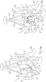
- Fig. 10a and b shows the inventive system including two devices 1 for displacing two adjacent vertebrae V1 and V2 in a spinal column in the process of positioning an alternatively configured implant 23' which is provided with a guiding fin 44 extending outwardly on each side of the implant 23'.
- the system is used according to what is shown in Fig 10a , wherein is shown a slot knife 46 being supported by the slide guide 43'.
- the slot knife 46 is thus pressed-in between the vertebrae when these are separated a predetermined distance, such that slots 45 having an adequate depth and width are formed in the adjacent vertebrae.
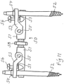
- Fig. 11 shows a variant of a device 50 according to the invention, wherein two end parts 51 are mutually rotational and displaceable by the intermediate of a centre screw-treaded element 58 such that these parts together form a rigging screw-like construction, whereby rotation of the element 58 displaces the end parts 51.
- Engagement elements 52 are locked with sleeves/nuts 54 and carried by support parts 53 that are pivotal over pins 55. The angular relationship between the engagement elements 52 and the parts 51 are adjusted by set screws 56 engaging counterparts 57 on the end parts.
- the system can have one single displacement device instead of two. At the ends, this single unit can have sideward angled bracket portions for cooperation at different positions along their lengths with typically each two engagement means that are engaged with the vertebrae so that the device according to the system will have a shallow U-shaped construction with the distance unit as the web and the sideward angled portions as the shanks of the U. In this case positioning, as an example, may need to be arranged on the one hand on the only distance device, on the other hand on a fixed point on a vertebra.
- the distance unit is maneuvered with the aid of an adjustment cable, such as a "Bowden cable", which can have its fastenings on engagement portions on mutually movable parts of a distance device in a manner which is per se obvious for the person skilled in the art.
- an adjustment cable such as a "Bowden cable”
- Other means for angular adjustment can also be employed.
- prostheses are positioned with a device according to the invention, for example vertebrae prostheses.
Landscapes
- Health & Medical Sciences (AREA)
- Orthopedic Medicine & Surgery (AREA)
- Neurology (AREA)
- Surgery (AREA)
- Life Sciences & Earth Sciences (AREA)
- Medical Informatics (AREA)
- Biomedical Technology (AREA)
- Heart & Thoracic Surgery (AREA)
- Engineering & Computer Science (AREA)
- Molecular Biology (AREA)
- Animal Behavior & Ethology (AREA)
- General Health & Medical Sciences (AREA)
- Public Health (AREA)
- Veterinary Medicine (AREA)
- Nuclear Medicine, Radiotherapy & Molecular Imaging (AREA)
- Prostheses (AREA)
- Surgical Instruments (AREA)
Description
- The invention concerns a device according to the preamble of
claim 1 and a system for engagement with vertebrae in a spinal column including such a device. The invention also concerns a use of the device. -
WO 06130085 - In particular,
WO 06130085 - When two distance means, carrying the engagement means, are arranged in parallel, handling of a holder and a prosthesis/an implant carried thereby takes place between these distance means.
- In
WO 06130085 -
WO 9002527 -
US 2371519 relates to extension and reduction appartus generally but is particularly intended for use in conjuction with installation of a ambulatory splint. A primary object of the invention resides in the provision of a small and light weight mechanism of which may rest upon the limb of a patient while being attached to the splint parts durign the process of aligning the bone fragments. - Even if the background art device functions well, it is an aim of the present invention to obtain a more versatile solution which can be used more freely for various bone displacing functions.
- This aim is achieved in a positioning device according to the above through the features of the characterizing portion of
claim 1. - When the arrangement for altering the angle includes an actuating unit which is maneuverable for pivotal adjustment of said angle, it is made possible on the one hand to control the device so as to increase the possibilities to manipulate the bones. It is further made possible to simply provide firm support in chosen angles for the engagement elements in respect of the distance units.
- This is advantageous compared to the device according to
WO 06130085 WO 06130085 - In the device of
WO 9002527 WO 9002527 - As a contrast, the device according to the invention has an arrangement allowing the angle of the respective engagement means to be independently adjustable, and parallel displacement is easily achieved.
- The present invention makes it possible to choose, obtain and lock not only the separation but also the angular positions of the bones (in particular vertebrae) with respect to each other and individually with respect of the distance unit. It is thus also possible to straighten up vertebrae in respect of each other or to obtain other desired relative positioning thereof.
- It is possible to "train" or mobilize ligaments also at inaccessible areas of a spinal column in a careful way, so as to create sufficient space between all parts of vertebrae for an implant leaving blood vessels, intestines, muscles etc. unharmed.
- The engagement elements are preferably elongated and have substantially longitudinal axes. In particular the engagement elements have screw treads for uncomplicated engagement with bones.
- When each support part is arranged to carry an engagement element in one mode where it is movable and in another mode where it is fixed, it is achieved that it can be engaged with a bone when in position in the device and subsequently be locked at a desired position.
- It is preferred that one of the support part and the support portion includes a pivotal pin which is pivotally supported by a corresponding bearing in turn being included in the other one of the support part and the support portion because of simplicity reasons. In particular, the engagement element is pivotal in a plane substantially parallel to or even including a straight line between two support portions on one distance unit.
- It is preferred that the actuating unit includes a setting element on one of the support parts and the support portion that is acting against a surface portion on the other one of the support part and the support portion. This provides a simple and simply operated solution. It is also preferred that the setting element is one from the group: a treaded sleeve, a screw, a nut, a cam.
- The distance unit has preferably means for controlled displacement of the support units in respect of each other in order to alter the degree of separation of said bones, since this provision allows for greater separating possibilities. The means for controlled displacement is thereby advantageously one from the group: screw means, rack and pawl, lever mechanism, telescopic elements, pneumatic means, hydraulic means.
- It is further preferred that it includes a special tool for manipulating said actuating unit and a tool for manipulating said engagement elements.
- The invention also concerns a system for engagement with vertebrae in a spinal column including at least one device for separating bones and a holder for a prosthesis from the group: a disc implant, a vertebral implant, said holder being adjustably fixable to e.g. an engagement element in the form of a bone screw over a specially constructed positioning arrangement, said holder preferably including a fork-shaped head for external or internal cooperation with the implant.
- The system preferably includes at least one supporting device which is fixed on said at lest one device for holding an operation point for engagement with vertebrae free from body organs.
- The system according to the invention includes, in a preferred embodiment, a positioning arrangement for an implant, wherein a positioning arm has a first portion for engagement with said distance unit and a second portion for engagement with an implant holder, and wherein the holder can be locked in a desired position. This allows secure positioning of the implant when completing the process of replacing a damaged body part.
- The invention will now be described by way of embodiments and with reference to the annexed drawings, wherein:
-
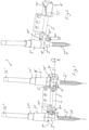
Fig. 1 shows a device according to the invention in a side view, -
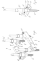
Fig. 2 shows two devices according to the invention in a perspective view, -
Figs. 3 and4 show the device inFig. 1 in perspective views with parts removed for clarity, -
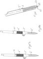
Figs. 5a and b show parts of a device according to the invention, -
Figs. 6 shows a part of an alternative engagement element according to the invention, -
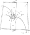
Fig. 7 shows parts of a system according to the invention during use, -
Fig. 8 shows the system with an implant holder, -
Fig. 9 a and b show a system according to the invention in different views, -
Figs. 10 a - b show parts of a system according to the invention during a second form of use, a tool for the manipulation of the device, and -
Fig. 11 shows an alternative displacement device. - In
Fig. 1 ,reference numeral 1 denotes a device for displacing bones. In particular thedevice 1 is intended and designed for the distraction of vertebra in a spinal column, so as to allow a surgeon access to an operation point between two vertebrae. The vertebrae are separated so as to e.g. remove a damaged disc in the process of replacing that disc with a prosthesis in the form a disc implant. In that process it is important to be able to completely clear out the region between the vertebrae, such that no parts of the damaged disc remain. - The device according to the invention simplifies the entire operation process which will result in a more secure and fast process.
- The
device 1 is comprised of twoengagement elements 2' and 2" which are positioned at a distance from each other and are carried byrespective support parts 3' and 3" which in turn are supported insupport portions 4' and 4" of adistance unit 5. Thedistance unit 5 is telescopic and capable of being extended such that thesupport portions 4' and 4" and thereby thesupport parts 3' and 3" and thus theengagement elements 2' and 2" are displaced in respect of each other. - A (not shown) tube transmits hydraulic medium used for actuating the
telescopic distance unit 5, said unit including a (not shown) piston-cylinder aggregate of a per se known kind. - The
engagement elements 2' and 2" each have a longitudinal axis, whereof one, A, for theengagement element 2", is shown in the Figure. A straight line between the two support units which are each made up by a support part and an associated support portion is indicated with L. As shown inFig. 1 , the longitudinal axis A ofengagement element 2" forms an angle α with said straight line L. In the shown embodiment, the line L is a symmetrical axis of a of thetelescopic distance unit 5. Alternatively, it can be said that the angle α is between the longitudinal axis A of therespective engagement element 2' and 2" and a plane through L and the axis of therespective pivot pin 13' and 13" (seefig 3 ). - In the
figure 2 ,5' indicates a piston rod being part of said piston - cylinder aggregate of thetelescopic distance unit 5. Extension of thetelescopic distance unit 5 is thus accomplished by the piston rod 5' being forced out from the housing of thetelescopic distance unit 5 in a manner which is per se known in respect of fluid operated piston - cylinder devices. Further, the piston rod 5' is rotatable (R inFig 1 ) in respect of the rest of thetelescopic distance unit 5 such that the relative rotational position of thesupport portions 4' and 4" and thereby theengagement elements 2' and 2" in respect of the symmetrical axis of thetelescopic distance unit 5 can be varied at will in order to adjust to various requirements on the particular case. - The
engagement elements 2' and 2" are shown having tapering portions directed downwardly inFig. 1 , and these tapering portions are provided with threads which are intended to engage possibly pre-drilled holes in bones such as vertebrae to be manipulated. - On the upper ends of the
engagement elements 2' and 2" there are positioned means for the control of the engagement elements in a way which will be explained below. - On the upper part of the engagement element 2' which is thus opposite to the tapering, threaded portion in respect of the support part 3', there is arranged a first rotatable sleeve 7' which is part of an actuating unit and is used for pivoted adjustment of the angle α. At that part of the engagement element 2' there is also arranged a second sleeve 11', which is used for locking the engagement element 2' inside the support part 3'.
- The actuating unit in respect of the engagement element 2' functions such that the first sleeve 7', which has a threaded inside engagement with a treaded outside on the support part 3' (see
Figs 5 and 6 ), through rotation of the first sleeve 7' will obtain an axial displacement along the support part 3' and thereby along the engagement element 2'. An end surface of the first sleeve 7' being directed axially and downwardly inFig. 1 and being indicated with 9' co-operates with a cam surface 10' which is situated on the support portion 4'. - Through this arrangement, rotation of the first sleeve 7' for a movement in the direction towards the tapering portion of the engagement element 2', will result in that the angle α increases. On the other hand, when the first sleeve 7' is rotated such that it with its end surface 9' is displaced in a direction away from the tapering portion of the engagement element 2', the angle α will decrease.
- Rotation of the second sleeve 11' is between a first mode, where the engagement element 2' is free to move axially inside the support part 3' as well as to rotate inside the support part 3', and a second mode, where the engagement element 2' is locked from axial movement and from rotation. Such a locking function can be easily accomplished for example by having an inside portion of the second sleeve 11' being inwardly conical and co-operating with a small sleeve surrounding the engagement element 2' and having a correspondingly conical upper outside surface (see
Fig. 5 ). - 12' and 12" indicate wrench engagement surfaces in the form of cut-ins so as to form planar surface portions. The engagement elements can of course also have other means for engagement with a wrench such as e.g. Allen key holes.
- The upper part of the first sleeve 7' is shown having a notch 8', which is intended to be engaged with a corresponding protrusion of a tool used for manipulating the
device 1 as will be described below. A corresponding notch is present on thesecond sleeve 11. - The device according to the invention is most often used in pairs, which is shown in
fig 2 . The two devices inFig 2 are identical for better ease of handling. Normally, when the device is installed in respect of bones such as vertebrae to be displaced (see alsofigs 7 and10a - c), firstly theengagement elements 2' and 2" are screwed into two adjacent vertebrae, whereby as advantageous positions as possible can be chosen in respect of bone strength etc. Thereupon thetelescopic distance units 5 are positioned by thesupport parts 3' and 3" being slid over and onto the fastenedengagement elements 2' and 2" such that their relative position will correspond essentially to what is shown inFigs. 2 ,7 and10a and c. By thesupport portions 4' and 4" being rotational with respect to each other and by thesupport parts 3' and 3" being pivotal, it should be understood that there is easy to find positions of thesupport parts 3' and 3" of thedevice 1 such that bores inside thesleeves 7', 7" can receive theengagement elements 2' and 2". Thereafter, the sleeves can be tightened for locking theengagement elements 2' and 2" and finally the displacement device be actuated for displacement. - 60 indicates holes for the connection of hoses for hydraulic fluid. When fluid is introduced into the
distance units 5, the piston rod 5' is pressed out from thetelescopic distance unit 5 so as to obtain a separating action. - In
Figs. 3 and4 are shown more details in respect of the support unit, wherein i.a. is shown in more detail a pivot pin 13', which is part of the support portion 4', stripped from thesupport part 3'. 14" indicates a washer/screw combination for securing thesupport part 3" on a pivot pin (not shown) corresponding to the pivot pin 13' and carrying a bearingportion 15" of thesupport part 3". In these figures, the cooperation between theend surface 9" and thecam surface 10" is shown in more detail. - With reference to all of
Figs 1, 3 and4 , since the support part 3' provides a distance between the pivot axis, being the axis of the pin 13', and the point of engagement between the surface 9' of the first sleeve 7' and the cam surface 10' of the support portion 4', the degree of adjustment of the angle α will be dependent on the distance between these points. -
Fig. 5a shows the support part 3' and the engagement element 2' in more detail. InFig. 5a , the first and second sleeves (seeFig 1 ) are removed and a treaded portion 6' is shown in its entirety. The treaded portion 6' co-operates with both of the first and second sleeves which thus have corresponding threads inside. The locking function for locking the engagement element 2' mentioned above is accomplished by having a inside portion of the second sleeve 11' being inwardly conical and co-operating with a small, interrupted sleeve 16 on the engagement element 2' and having a correspondingly conical upper outside surface. Tightening of the sleeve 11' (seeFig 5b ) will accomplish clamping of the interrupted sleeve 16 on the engagement element 2' and locking it to the support part 3'. - Such arrangements are per se known in various arrangements, for example in respect of pipe couplings, and are therefore not further explained here.
-
Fig. 6 shows an alternative the engagement element 2' in more detail. This engagement element 2' is distinguished from the one shown in previous figures in that the screw point 61 is constructed differently, with a peg-shapedextension 62 and anabutment surface 63, which forms a blunt angle to a symmetry axis S through the element 2'. This construction makes it easier to detect when the screw (element) 2' has reached a correct position in a vertebra, since it makes it possible for the surgeon to sense when the screw has passed the front cortical part thereof, the spongy inside of the vertebra and reached the rearward cortical part thereof such that the screw will be accurately engaging the hard portions of the vertebra in front and rear portions for best reception of the load. -
Fig. 7 shows, diagrammatically, a system including twodevices 1 for displacing two adjacent vertebrae V1 and V2 in a spinal column which is accessed through a cut C through the abdomen of a patient. The system is shown in an early step in the process of replacing a damaged disc in a spinal column of a human with an implant. The system includes an arrangement according to the invention, wherein thedevices 1 have been activated so as to separate the vertebrae V1 and V2. - The damaged disc has been removed so as to leave an empty space E between the vertebrae V1 and V2, wherein an implant is intended to be positioned. The two
devices 1 are here shown completed withdeflectors 27' and 27" that are designed to deflect sides of the cut C and body organs in the region of the operation point so as to allow better working conditions for the surgeon. Hereby, firstly, the spinal column is somewhat lifted in respect of the abdomen, giving the surgeon better working space and reduced depth through the cut C down to the spinal column. Secondly, the body organs are gently removed from the operation point and securely stabilized sideways thereof. - The
deflectors 27' and 27" include slightly curved panel portions and hook-like, first fastening portions, which are best shown infig 9a and indicated with 28' and 28", for engagement with therespective distance unit 5. Further, the deflectors include, hook-like,second fastening portions 29' and 29" for the engagement with a tighteningframe 30, having transversal elements for engagement with thesecond fastening portions 29' and 29" and longitudinal elements forming arectangular frame 30. The transversal elements can be separated so as to obtain a down-holding and spreading effect to thedeflectors 27' and 27". -
Fig. 8 shows diagrammatically a later step in the process of replacing a damaged disc. Here the deflectors and also other details are removed for clarity purposes only. The system is here shown with apositioning arrangement 22 for animplant 23. An exemplary embodiment of aholder 26 for theimplant 23 has a gripper head 32 which can be manipulated by relative axial movements of twoknobs - The
holder 26 is over a an extendable and mutuallylockable support member 35, 39 connected to a positioning arm in the form of a fixingdevice 36 which can be fastened (at 37) to the upper part of one of the engagement elements of the device in the above mentioned figures. A rotation and slide joint, at 41, can be locked so as to lock a stem portion of the fixingdevice 36 to thesupport member 35, 39 for preventing any mutual movement (slide through and articulation of the joint) of these elements by rotating a lockingknob 40. - By rotating a second locking knob 38 maneuvering a similar rotation and slide joint at 39, the
holder 26 can be locked to the support member at the end with numeral 39 in the same way. At the same time, a slotted portion 39', which is fitted inside a channel, (not shown) in the element indicated with 35 is brought to expand sideways, whereby a mutual telescopic movement of theelement 39,39' in respect of the element 35 can be locked. - Locking of 38 -39, 35 - 39 and 40 - 41 thus results in complete locking of the
entire positioning arrangement 22. - In practice, the joints at 39 and 41 are per se known joints with slotted spherical sleeves, each including a conical, inner, axially displaceable elements allowing free manipulation in released state and providing locking in the locked state. By rotating the locking knob, the conical, inner, axially displaceable element provokes an expansion of the slotted spherical sleeve and locks the angle and the passage through the joint.
- In locked mode, thus the guiding head 32 fixes the position of the
implant 23 prior to releasing thedevice 1 for displacing/separating the vertebrae so that it can be ensured that the implant is correctly positioned, for example with the aid of real time X-ray imaging. - Further, when releasing the
devices 1, the vertebrae are allowed to approach each other with the implant accurately positioned in between. - For the sake of clarity, parts of engagement elements have been removed. In this case, as is normally the case, two engagement elements have been screwed into each one of the vertebrae, whereupon the telescopic distance units 5 (see e.g.
fig 1 ) have been actuated for separation of the vertebrae V1 and V2. The angular adjustment of the engagement elements can then be individually set by rotation of the respectivefirst sleeves 7' and 7" ( see e.g.fig 1 ). Hereby the angles between the vertebrae can be accurately adjusted if necessary. - In order to arrange a greater space between two distance devices, the attachments of the engagement means are most preferred positioned sideways, outwardly, so that the distance units can be positioned sideways with respect of the axes of the engagement means.
-
Figs, 9a and b show an arrangement according to the invention, with thedevices 1 completed with thedeflectors 27' and 27". - 31' and 31" indicate hydraulic pressurizers for supplying hydraulic fluid to the distance units upon rotation of respective end knobs.
- Tools for rotating the first and
second sleeves 7' and 7" (seefig 1 ) can be designed to have tubular parts that are provided with protrusions on one end for co-operation with the notches of the sleeves. On an opposite end, the tubular parts can have rotation knobs. In order to rotate the sleeves, the tubular parts are simply slid over the free portions of the engagement elements. -
Fig. 10a and b shows the inventive system including twodevices 1 for displacing two adjacent vertebrae V1 and V2 in a spinal column in the process of positioning an alternatively configured implant 23' which is provided with a guidingfin 44 extending outwardly on each side of the implant 23'. In order to make guidingslots 45 in the vertebrae, the system is used according to what is shown inFig 10a , wherein is shown aslot knife 46 being supported by the slide guide 43'. - The
slot knife 46 is thus pressed-in between the vertebrae when these are separated a predetermined distance, such thatslots 45 having an adequate depth and width are formed in the adjacent vertebrae. - This use of the inventive system provides an advantage compared to the background art, since it gives the possibility to form the
slots 45 in the vertebrae in a simple way with precision and little effort. The implant 23' can subsequently be positioned as is shown in Fig 10c with thefins 44 being guided.by theslots 45 into a desired position between the vertebrae V1 and V2. - In common for the positioning in
figs 8 and10b is that the implant can be positioned gently without requirement for the relatively violent hammering action, which unfortunately has to be employed for implanting discs according to today's common practice. -
Fig. 11 shows a variant of adevice 50 according to the invention, wherein twoend parts 51 are mutually rotational and displaceable by the intermediate of a centre screw-treadedelement 58 such that these parts together form a rigging screw-like construction, whereby rotation of theelement 58 displaces theend parts 51.Engagement elements 52 are locked with sleeves/nuts 54 and carried bysupport parts 53 that are pivotal over pins 55. The angular relationship between theengagement elements 52 and theparts 51 are adjusted byset screws 56engaging counterparts 57 on the end parts. - Various modifications of the invention can be made within the scope of the claims. The system can have one single displacement device instead of two. At the ends, this single unit can have sideward angled bracket portions for cooperation at different positions along their lengths with typically each two engagement means that are engaged with the vertebrae so that the device according to the system will have a shallow U-shaped construction with the distance unit as the web and the sideward angled portions as the shanks of the U. In this case positioning, as an example, may need to be arranged on the one hand on the only distance device, on the other hand on a fixed point on a vertebra.
- Also other kinds of arrangements for locking the holder can be envisaged, for example with a locking device arranged at the fastening point of the
arms - In a simple modification, the distance unit is maneuvered with the aid of an adjustment cable, such as a "Bowden cable", which can have its fastenings on engagement portions on mutually movable parts of a distance device in a manner which is per se obvious for the person skilled in the art. Other means for angular adjustment can also be employed.
- It shall be noted that it is not excluded that other prostheses are positioned with a device according to the invention, for example vertebrae prostheses.
Claims (13)
- Device (1) for displacing vertebrae in a spinal column of a living mammal, including at least two engagement elements (2', 2"), positioned at a distance from each other, for engagement with two separate vertebrae,- wherein each one of said engagement elements (2', 2") is carried by a support part (3', 3") having external threads and which in turn is supported in a support portion (4', 4") of a distance unit (5), said support part and support portion forming a support unit,- wherein the distance unit (5, 5') has means for controlled displacement of the support units in respect of each other in order to alter the degree of separation of said vertebrae- wherein each engagement element (2', 2") extends at an angle (a) with respect to a straight line (L) between two support units,- wherein the engagement elements (2', 2") are elongated and have substantially longitudinal axes (A),- wherein at least one of said support units includes an arrangement for altering said angle, and- wherein each said arrangement for altering said angle includes an actuating unit (7', 7", 9', 9", 10', 10") which is maneuverable for adjustment of said angle (a) individually in respect of the support part, characterized in- that the actuating unit includes a sleeve (7', 7") on one of the support part and the support portion, which sleeve is acting against a surface portion (10', 10") on the other one of the support part and the support portion, whereinthe sleeve has internal threads for engagement with the external threads of the support part and having an end surface (9', 9"),the end surface is co-operating with a cam surface (10') situated on the surface portion (4'), andthe sleeve is configured to rotate and thereby axially displace the support part and correspondingly along the engagement element,- that one of the support part and the support portion includes a pivotal (13', 13") pin which is in pivotal cooperation with a bearing (15', 15") being included in the other one of the support part and the support portion.
- Device according to claim 1, characterized in that the engagement elements (2', 2") have screw treads for engagement with vertebrae.
- Device according to claim 1 or 2, characterized in that each support part (3', 3") is arranged to carry an engagement element (2', 2") in a mode where it is adjustable and in a mode where it is fixed.
- Device according to any one of the previous claims, characterized in that the setting element (7', 7") is one from the group: a treaded sleeve, a screw, a nut, a cam.
- Device according to any one of the previous claims, characterized in that the means for controlled displacement is one from the group: screw means, rack and pawl, lever mechanism, telescopic elements, pneumatic means, hydraulic means.
- Device according to any one of the previous claims, characterized in that he distance unit (5) is telescopic and capable of being extended such that the support portions (4' and 4") and thereby the support parts (3' and 3") and thus the engagement elements (2' and 2") are displaced in respect of each other.
- Device according to any one of the previous claims, characterized in that the support portions (4', 4") of one distance unit (5) are rotational (R) relative to each other around a symmetry axis (L) for a piston-cylinder aggregate being included in the distance unit (5,5').
- System for engagement with vertebrae in a spinal column including at least one device according to any one of the claims 1 - 7 and a holder (26) for a prosthesis (23) from the group: a disc implant, a vertebral implant, said holder being adjustably fixable to said at least one device.
- System according to claim 8, characterized in that said holder (26) includes a fork-shaped head for external or internal co-operation with the implant (23).
- System according to claim 8 or 9, characterized in that it includes at least one deflector (27', 27") which is fixed on said at least one device (1), for holding an operation point for engagement with vertebrae free from body organs.
- System according to any one of the claims 8 - 10, characterized in that it includes a positioning arrangement for an implant, wherein at least one positioning arm (24, 25; 36) has a first portion for engagement with said displacement device and a second portion for engagement with a holder (26) for an implant (23), and wherein the holder is fastenable in a desired position.
- System according to any one of the claims 8 - 11, characterized in that it includes a tool for manipulating said actuating unit.
- System according to any one of the claims 8 - 12, characterized in that it includes a tool for manipulating said engagement elements.
Applications Claiming Priority (3)
| Application Number | Priority Date | Filing Date | Title |
|---|---|---|---|
| SE0801246A SE533231C2 (en) | 2008-05-28 | 2008-05-28 | Moving device, its use and a system therefor |
| US12/130,490 US8154562B2 (en) | 2007-06-01 | 2008-05-30 | Method and arrangement for improving the grayscale resolution of a monochrome monitor |
| PCT/SE2009/000275 WO2009145696A1 (en) | 2008-05-28 | 2009-05-28 | Device and a system for displacing bones |
Publications (3)
| Publication Number | Publication Date |
|---|---|
| EP2293731A1 EP2293731A1 (en) | 2011-03-16 |
| EP2293731A4 EP2293731A4 (en) | 2013-05-29 |
| EP2293731B1 true EP2293731B1 (en) | 2022-03-09 |
Family
ID=41377328
Family Applications (1)
| Application Number | Title | Priority Date | Filing Date |
|---|---|---|---|
| EP09755134.5A Not-in-force EP2293731B1 (en) | 2008-05-28 | 2009-05-28 | Device and a system for displacing bones |
Country Status (5)
| Country | Link |
|---|---|
| US (1) | US8764800B2 (en) |
| EP (1) | EP2293731B1 (en) |
| CA (1) | CA2725332C (en) |
| SE (1) | SE533231C2 (en) |
| WO (1) | WO2009145696A1 (en) |
Families Citing this family (10)
| Publication number | Priority date | Publication date | Assignee | Title |
|---|---|---|---|---|
| US7776072B2 (en) | 2004-12-30 | 2010-08-17 | Barry Mark A | System and method for aligning vertebrae in the amelioration of aberrant spinal column deviation conditions |
| US9339301B2 (en) | 2004-12-30 | 2016-05-17 | Mark A. Barry | System and method for aligning vertebrae in the amelioration of aberrant spinal column deviation conditions |
| US9808281B2 (en) * | 2009-05-20 | 2017-11-07 | DePuy Synthes Products, Inc. | Patient-mounted retraction |
| JP2013512040A (en) * | 2009-11-25 | 2013-04-11 | スパイン21エル・ティー・ディー | Spinal rod with adjustable dimensions after surgery |
| US8535318B2 (en) | 2010-04-23 | 2013-09-17 | DePuy Synthes Products, LLC | Minimally invasive instrument set, devices and related methods |
| US9907582B1 (en) | 2011-04-25 | 2018-03-06 | Nuvasive, Inc. | Minimally invasive spinal fixation system and related methods |
| EP2886074B1 (en) * | 2013-12-20 | 2016-09-14 | Biedermann Technologies GmbH & Co. KG | Rod insertion device |
| US10194960B1 (en) | 2015-12-03 | 2019-02-05 | Nuvasive, Inc. | Spinal compression instrument and related methods |
| US10952714B1 (en) | 2017-07-14 | 2021-03-23 | OrtoWay AB | Apparatus, methods and systems for spine surgery |
| CN109330643B (en) * | 2018-10-19 | 2019-12-13 | 中国人民解放军第二军医大学第二附属医院 | Centrum lifting and expanding device |
Citations (1)
| Publication number | Priority date | Publication date | Assignee | Title |
|---|---|---|---|---|
| US2371519A (en) * | 1942-11-12 | 1945-03-13 | Herbert H Haynes | Extension and reduction appliance |
Family Cites Families (28)
| Publication number | Priority date | Publication date | Assignee | Title |
|---|---|---|---|---|
| US4386603A (en) * | 1981-03-23 | 1983-06-07 | Mayfield Jack K | Distraction device for spinal distraction systems |
| DE3306657C2 (en) * | 1983-02-25 | 1986-12-11 | Fa. Heinrich C. Ulrich, 7900 Ulm | Spine correction implant with a distraction rod |
| US4611580A (en) * | 1983-11-23 | 1986-09-16 | Henry Ford Hospital | Intervertebral body stabilization |
| DE3414374C2 (en) * | 1984-04-16 | 1986-12-18 | Patrick Dr. 3590 Bad Wildungen Kluger | Device for setting up a spine with damaged vertebral bodies |
| DE8704134U1 (en) * | 1987-03-19 | 1987-07-16 | Zielke, Klaus, Dr.med., 3590 Bad Wildungen | Implant designed as a distraction and compression rod |
| DE3733924C2 (en) * | 1987-10-07 | 1997-06-19 | Gotzen Leo Prof Dr | Spine fixation device |
| WO1990002527A1 (en) | 1988-09-09 | 1990-03-22 | Australian Defence Industries Pty. Limited | Spinal distractor |
| US5219349A (en) * | 1991-02-15 | 1993-06-15 | Howmedica, Inc. | Spinal fixator reduction frame |
| US5304179A (en) * | 1993-06-17 | 1994-04-19 | Amei Technologies Inc. | System and method for installing a spinal fixation system at variable angles |
| US5431658A (en) * | 1994-02-14 | 1995-07-11 | Moskovich; Ronald | Facilitator for vertebrae grafts and prostheses |
| DE29814174U1 (en) | 1998-08-07 | 1999-12-16 | Howmedica GmbH, 24232 Schönkirchen | Instruments for inserting an implant into the human spine |
| CA2392868C (en) * | 1999-12-01 | 2008-08-05 | Henry Graf | Intervertebral stabilising device |
| US6565568B1 (en) * | 2000-09-28 | 2003-05-20 | Chaim Rogozinski | Apparatus and method for the manipulation of the spine and sacrum in the treatment of spondylolisthesis |
| EP1222903B1 (en) * | 2001-01-12 | 2005-01-19 | Link Spine Group, Inc. | Surgical instrument for implanting an intervertebral prosthesis |
| US20050143747A1 (en) * | 2001-07-16 | 2005-06-30 | Rafail Zubok | Parallel distractor and related methods for use in implanting an artificial intervertebral disc |
| CA2702131A1 (en) * | 2002-03-11 | 2003-09-25 | Zimmer Spine, Inc. | Instrumentation and procedure for implanting spinal implant devices |
| US7588573B2 (en) * | 2002-09-23 | 2009-09-15 | Warsaw Orthopedic, Inc. | Expansion tool for adjustable spinal implant |
| US20040148028A1 (en) * | 2002-12-19 | 2004-07-29 | Ferree Bret A. | Artificial disc replacement (ADR) extraction methods and apparatus |
| US20040158254A1 (en) * | 2003-02-12 | 2004-08-12 | Sdgi Holdings, Inc. | Instrument and method for milling a path into bone |
| US8652175B2 (en) * | 2003-05-02 | 2014-02-18 | Rachiotek, Llc | Surgical implant devices and systems including a sheath member |
| US7491168B2 (en) * | 2003-12-18 | 2009-02-17 | Depuy Spine, Inc. | Surgical retractor systems and illuminated cannulae |
| US20050203532A1 (en) * | 2004-03-12 | 2005-09-15 | Sdgi Holdings, Inc. | Technique and instrumentation for intervertebral prosthesis implantation using independent landmarks |
| US7776051B2 (en) * | 2004-05-03 | 2010-08-17 | Theken Spine, Llc | System and method for displacement of bony structures |
| SE528709C8 (en) | 2005-06-01 | 2007-03-13 | Ortoviva Ab | Positioning device for a prosthetic device and system therefor |
| US20080077155A1 (en) * | 2006-09-25 | 2008-03-27 | Jennifer Diederich | System and method for displacement of bony structures |
| US20080172062A1 (en) * | 2007-01-12 | 2008-07-17 | Depuy Spine, Inc. | Bone anchor manipulation device |
| EP2446841B1 (en) * | 2010-10-28 | 2013-05-29 | Stryker Trauma SA | Bolt and tool with anti-torque features |
| US9265528B2 (en) * | 2010-11-30 | 2016-02-23 | Nikolaj Wolfson | Orthopedic fixation systems and methods |
-
2008
- 2008-05-28 SE SE0801246A patent/SE533231C2/en not_active IP Right Cessation
-
2009
- 2009-05-28 CA CA2725332A patent/CA2725332C/en active Active
- 2009-05-28 WO PCT/SE2009/000275 patent/WO2009145696A1/en not_active Ceased
- 2009-05-28 EP EP09755134.5A patent/EP2293731B1/en not_active Not-in-force
- 2009-05-28 US US12/994,654 patent/US8764800B2/en active Active - Reinstated
Patent Citations (1)
| Publication number | Priority date | Publication date | Assignee | Title |
|---|---|---|---|---|
| US2371519A (en) * | 1942-11-12 | 1945-03-13 | Herbert H Haynes | Extension and reduction appliance |
Also Published As
| Publication number | Publication date |
|---|---|
| US8764800B2 (en) | 2014-07-01 |
| CA2725332A1 (en) | 2009-12-03 |
| SE0801246L (en) | 2009-11-29 |
| WO2009145696A1 (en) | 2009-12-03 |
| US20110190820A1 (en) | 2011-08-04 |
| SE533231C2 (en) | 2010-07-27 |
| EP2293731A4 (en) | 2013-05-29 |
| CA2725332C (en) | 2018-07-17 |
| EP2293731A1 (en) | 2011-03-16 |
Similar Documents
| Publication | Publication Date | Title |
|---|---|---|
| CA2725332C (en) | Device and a system for displacing bones | |
| JP6728411B2 (en) | Tissue retracting and vertebral displacement devices, systems and methods for posterior spinal fusion | |
| US8075565B2 (en) | Surgical instruments for delivering forces to bony structures | |
| US8097027B2 (en) | Minimally invasive instruments and methods for inserting implants | |
| EP3351185B1 (en) | Soft tissue retractor | |
| JP5543964B2 (en) | Rod reduction device | |
| US9848863B2 (en) | Surgical retractor systems and methods | |
| EP3352683B1 (en) | Distractor device | |
| JP7137736B2 (en) | articulating rod insert | |
| KR20080004444A (en) | Spinal Surgery Braces | |
| JP2019516467A (en) | Medical device for temporarily fastening multiaxial pedicle screws | |
| EP3047811B1 (en) | Rod reducer | |
| KR20090005316A (en) | Minimally invasive fixation system | |
| JP6871282B2 (en) | Spinal repositioning device and spinal repositioning system | |
| US20230329758A1 (en) | Adjustable, modular instrument and method for spinal manipulation | |
| US20090216239A1 (en) | Positioning Device for a Prosthesis Device and System Therefore | |
| RU2325861C2 (en) | Implantation method for prosthesis of intervertebral disk and device for its realisation | |
| HK1079075B (en) | Minimally invasive instruments and methods for inserting implants |
Legal Events
| Date | Code | Title | Description |
|---|---|---|---|
| PUAI | Public reference made under article 153(3) epc to a published international application that has entered the european phase |
Free format text: ORIGINAL CODE: 0009012 |
|
| 17P | Request for examination filed |
Effective date: 20101214 |
|
| AK | Designated contracting states |
Kind code of ref document: A1 Designated state(s): AT BE BG CH CY CZ DE DK EE ES FI FR GB GR HR HU IE IS IT LI LT LU LV MC MK MT NL NO PL PT RO SE SI SK TR |
|
| AX | Request for extension of the european patent |
Extension state: AL BA RS |
|
| DAX | Request for extension of the european patent (deleted) | ||
| RAP1 | Party data changed (applicant data changed or rights of an application transferred) |
Owner name: ORTOWAY AB |
|
| A4 | Supplementary search report drawn up and despatched |
Effective date: 20130425 |
|
| RIC1 | Information provided on ipc code assigned before grant |
Ipc: A61B 17/66 20060101ALI20130419BHEP Ipc: A61B 17/70 20060101ALI20130419BHEP Ipc: A61B 17/88 20060101AFI20130419BHEP |
|
| STAA | Information on the status of an ep patent application or granted ep patent |
Free format text: STATUS: EXAMINATION IS IN PROGRESS |
|
| 17Q | First examination report despatched |
Effective date: 20170911 |
|
| GRAP | Despatch of communication of intention to grant a patent |
Free format text: ORIGINAL CODE: EPIDOSNIGR1 |
|
| STAA | Information on the status of an ep patent application or granted ep patent |
Free format text: STATUS: GRANT OF PATENT IS INTENDED |
|
| INTG | Intention to grant announced |
Effective date: 20210723 |
|
| GRAJ | Information related to disapproval of communication of intention to grant by the applicant or resumption of examination proceedings by the epo deleted |
Free format text: ORIGINAL CODE: EPIDOSDIGR1 |
|
| STAA | Information on the status of an ep patent application or granted ep patent |
Free format text: STATUS: EXAMINATION IS IN PROGRESS |
|
| INTC | Intention to grant announced (deleted) | ||
| GRAP | Despatch of communication of intention to grant a patent |
Free format text: ORIGINAL CODE: EPIDOSNIGR1 |
|
| STAA | Information on the status of an ep patent application or granted ep patent |
Free format text: STATUS: GRANT OF PATENT IS INTENDED |
|
| GRAS | Grant fee paid |
Free format text: ORIGINAL CODE: EPIDOSNIGR3 |
|
| GRAA | (expected) grant |
Free format text: ORIGINAL CODE: 0009210 |
|
| STAA | Information on the status of an ep patent application or granted ep patent |
Free format text: STATUS: THE PATENT HAS BEEN GRANTED |
|
| INTG | Intention to grant announced |
Effective date: 20220118 |
|
| AK | Designated contracting states |
Kind code of ref document: B1 Designated state(s): AT BE BG CH CY CZ DE DK EE ES FI FR GB GR HR HU IE IS IT LI LT LU LV MC MK MT NL NO PL PT RO SE SI SK TR |
|
| REG | Reference to a national code |
Ref country code: GB Ref legal event code: FG4D |
|
| REG | Reference to a national code |
Ref country code: CH Ref legal event code: EP Ref country code: AT Ref legal event code: REF Ref document number: 1473506 Country of ref document: AT Kind code of ref document: T Effective date: 20220315 |
|
| REG | Reference to a national code |
Ref country code: DE Ref legal event code: R096 Ref document number: 602009064330 Country of ref document: DE |
|
| REG | Reference to a national code |
Ref country code: IE Ref legal event code: FG4D |
|
| REG | Reference to a national code |
Ref country code: LT Ref legal event code: MG9D |
|
| REG | Reference to a national code |
Ref country code: NL Ref legal event code: MP Effective date: 20220309 |
|
| PG25 | Lapsed in a contracting state [announced via postgrant information from national office to epo] |
Ref country code: SE Free format text: LAPSE BECAUSE OF FAILURE TO SUBMIT A TRANSLATION OF THE DESCRIPTION OR TO PAY THE FEE WITHIN THE PRESCRIBED TIME-LIMIT Effective date: 20220309 Ref country code: NO Free format text: LAPSE BECAUSE OF FAILURE TO SUBMIT A TRANSLATION OF THE DESCRIPTION OR TO PAY THE FEE WITHIN THE PRESCRIBED TIME-LIMIT Effective date: 20220609 Ref country code: LT Free format text: LAPSE BECAUSE OF FAILURE TO SUBMIT A TRANSLATION OF THE DESCRIPTION OR TO PAY THE FEE WITHIN THE PRESCRIBED TIME-LIMIT Effective date: 20220309 Ref country code: HR Free format text: LAPSE BECAUSE OF FAILURE TO SUBMIT A TRANSLATION OF THE DESCRIPTION OR TO PAY THE FEE WITHIN THE PRESCRIBED TIME-LIMIT Effective date: 20220309 Ref country code: BG Free format text: LAPSE BECAUSE OF FAILURE TO SUBMIT A TRANSLATION OF THE DESCRIPTION OR TO PAY THE FEE WITHIN THE PRESCRIBED TIME-LIMIT Effective date: 20220609 |
|
| REG | Reference to a national code |
Ref country code: AT Ref legal event code: MK05 Ref document number: 1473506 Country of ref document: AT Kind code of ref document: T Effective date: 20220309 |
|
| PG25 | Lapsed in a contracting state [announced via postgrant information from national office to epo] |
Ref country code: LV Free format text: LAPSE BECAUSE OF FAILURE TO SUBMIT A TRANSLATION OF THE DESCRIPTION OR TO PAY THE FEE WITHIN THE PRESCRIBED TIME-LIMIT Effective date: 20220309 Ref country code: GR Free format text: LAPSE BECAUSE OF FAILURE TO SUBMIT A TRANSLATION OF THE DESCRIPTION OR TO PAY THE FEE WITHIN THE PRESCRIBED TIME-LIMIT Effective date: 20220610 Ref country code: FI Free format text: LAPSE BECAUSE OF FAILURE TO SUBMIT A TRANSLATION OF THE DESCRIPTION OR TO PAY THE FEE WITHIN THE PRESCRIBED TIME-LIMIT Effective date: 20220309 |
|
| PG25 | Lapsed in a contracting state [announced via postgrant information from national office to epo] |
Ref country code: NL Free format text: LAPSE BECAUSE OF FAILURE TO SUBMIT A TRANSLATION OF THE DESCRIPTION OR TO PAY THE FEE WITHIN THE PRESCRIBED TIME-LIMIT Effective date: 20220309 |
|
| PG25 | Lapsed in a contracting state [announced via postgrant information from national office to epo] |
Ref country code: SK Free format text: LAPSE BECAUSE OF FAILURE TO SUBMIT A TRANSLATION OF THE DESCRIPTION OR TO PAY THE FEE WITHIN THE PRESCRIBED TIME-LIMIT Effective date: 20220309 Ref country code: RO Free format text: LAPSE BECAUSE OF FAILURE TO SUBMIT A TRANSLATION OF THE DESCRIPTION OR TO PAY THE FEE WITHIN THE PRESCRIBED TIME-LIMIT Effective date: 20220309 Ref country code: PT Free format text: LAPSE BECAUSE OF FAILURE TO SUBMIT A TRANSLATION OF THE DESCRIPTION OR TO PAY THE FEE WITHIN THE PRESCRIBED TIME-LIMIT Effective date: 20220711 Ref country code: ES Free format text: LAPSE BECAUSE OF FAILURE TO SUBMIT A TRANSLATION OF THE DESCRIPTION OR TO PAY THE FEE WITHIN THE PRESCRIBED TIME-LIMIT Effective date: 20220309 Ref country code: EE Free format text: LAPSE BECAUSE OF FAILURE TO SUBMIT A TRANSLATION OF THE DESCRIPTION OR TO PAY THE FEE WITHIN THE PRESCRIBED TIME-LIMIT Effective date: 20220309 Ref country code: CZ Free format text: LAPSE BECAUSE OF FAILURE TO SUBMIT A TRANSLATION OF THE DESCRIPTION OR TO PAY THE FEE WITHIN THE PRESCRIBED TIME-LIMIT Effective date: 20220309 Ref country code: AT Free format text: LAPSE BECAUSE OF FAILURE TO SUBMIT A TRANSLATION OF THE DESCRIPTION OR TO PAY THE FEE WITHIN THE PRESCRIBED TIME-LIMIT Effective date: 20220309 |
|
| PG25 | Lapsed in a contracting state [announced via postgrant information from national office to epo] |
Ref country code: PL Free format text: LAPSE BECAUSE OF FAILURE TO SUBMIT A TRANSLATION OF THE DESCRIPTION OR TO PAY THE FEE WITHIN THE PRESCRIBED TIME-LIMIT Effective date: 20220309 Ref country code: IS Free format text: LAPSE BECAUSE OF FAILURE TO SUBMIT A TRANSLATION OF THE DESCRIPTION OR TO PAY THE FEE WITHIN THE PRESCRIBED TIME-LIMIT Effective date: 20220709 |
|
| REG | Reference to a national code |
Ref country code: DE Ref legal event code: R097 Ref document number: 602009064330 Country of ref document: DE |
|
| REG | Reference to a national code |
Ref country code: CH Ref legal event code: PL |
|
| PLBE | No opposition filed within time limit |
Free format text: ORIGINAL CODE: 0009261 |
|
| STAA | Information on the status of an ep patent application or granted ep patent |
Free format text: STATUS: NO OPPOSITION FILED WITHIN TIME LIMIT |
|
| REG | Reference to a national code |
Ref country code: BE Ref legal event code: MM Effective date: 20220531 |
|
| PG25 | Lapsed in a contracting state [announced via postgrant information from national office to epo] |
Ref country code: MC Free format text: LAPSE BECAUSE OF FAILURE TO SUBMIT A TRANSLATION OF THE DESCRIPTION OR TO PAY THE FEE WITHIN THE PRESCRIBED TIME-LIMIT Effective date: 20220309 Ref country code: LU Free format text: LAPSE BECAUSE OF NON-PAYMENT OF DUE FEES Effective date: 20220528 Ref country code: LI Free format text: LAPSE BECAUSE OF NON-PAYMENT OF DUE FEES Effective date: 20220531 Ref country code: DK Free format text: LAPSE BECAUSE OF FAILURE TO SUBMIT A TRANSLATION OF THE DESCRIPTION OR TO PAY THE FEE WITHIN THE PRESCRIBED TIME-LIMIT Effective date: 20220309 Ref country code: CH Free format text: LAPSE BECAUSE OF NON-PAYMENT OF DUE FEES Effective date: 20220531 |
|
| 26N | No opposition filed |
Effective date: 20221212 |
|
| PG25 | Lapsed in a contracting state [announced via postgrant information from national office to epo] |
Ref country code: SI Free format text: LAPSE BECAUSE OF FAILURE TO SUBMIT A TRANSLATION OF THE DESCRIPTION OR TO PAY THE FEE WITHIN THE PRESCRIBED TIME-LIMIT Effective date: 20220309 |
|
| PG25 | Lapsed in a contracting state [announced via postgrant information from national office to epo] |
Ref country code: IE Free format text: LAPSE BECAUSE OF NON-PAYMENT OF DUE FEES Effective date: 20220528 |
|
| PG25 | Lapsed in a contracting state [announced via postgrant information from national office to epo] |
Ref country code: BE Free format text: LAPSE BECAUSE OF NON-PAYMENT OF DUE FEES Effective date: 20220531 |
|
| PG25 | Lapsed in a contracting state [announced via postgrant information from national office to epo] |
Ref country code: IT Free format text: LAPSE BECAUSE OF FAILURE TO SUBMIT A TRANSLATION OF THE DESCRIPTION OR TO PAY THE FEE WITHIN THE PRESCRIBED TIME-LIMIT Effective date: 20220309 |
|
| PGFP | Annual fee paid to national office [announced via postgrant information from national office to epo] |
Ref country code: GB Payment date: 20230816 Year of fee payment: 15 |
|
| PGFP | Annual fee paid to national office [announced via postgrant information from national office to epo] |
Ref country code: FR Payment date: 20230816 Year of fee payment: 15 Ref country code: DE Payment date: 20230818 Year of fee payment: 15 |
|
| PG25 | Lapsed in a contracting state [announced via postgrant information from national office to epo] |
Ref country code: HU Free format text: LAPSE BECAUSE OF FAILURE TO SUBMIT A TRANSLATION OF THE DESCRIPTION OR TO PAY THE FEE WITHIN THE PRESCRIBED TIME-LIMIT; INVALID AB INITIO Effective date: 20090528 |
|
| PG25 | Lapsed in a contracting state [announced via postgrant information from national office to epo] |
Ref country code: MK Free format text: LAPSE BECAUSE OF FAILURE TO SUBMIT A TRANSLATION OF THE DESCRIPTION OR TO PAY THE FEE WITHIN THE PRESCRIBED TIME-LIMIT Effective date: 20220309 Ref country code: CY Free format text: LAPSE BECAUSE OF FAILURE TO SUBMIT A TRANSLATION OF THE DESCRIPTION OR TO PAY THE FEE WITHIN THE PRESCRIBED TIME-LIMIT Effective date: 20220309 |
|
| PG25 | Lapsed in a contracting state [announced via postgrant information from national office to epo] |
Ref country code: TR Free format text: LAPSE BECAUSE OF FAILURE TO SUBMIT A TRANSLATION OF THE DESCRIPTION OR TO PAY THE FEE WITHIN THE PRESCRIBED TIME-LIMIT Effective date: 20220309 |
|
| PG25 | Lapsed in a contracting state [announced via postgrant information from national office to epo] |
Ref country code: MT Free format text: LAPSE BECAUSE OF FAILURE TO SUBMIT A TRANSLATION OF THE DESCRIPTION OR TO PAY THE FEE WITHIN THE PRESCRIBED TIME-LIMIT Effective date: 20220309 |
|
| REG | Reference to a national code |
Ref country code: DE Ref legal event code: R119 Ref document number: 602009064330 Country of ref document: DE |
|
| GBPC | Gb: european patent ceased through non-payment of renewal fee |
Effective date: 20240528 |
|
| PG25 | Lapsed in a contracting state [announced via postgrant information from national office to epo] |
Ref country code: DE Free format text: LAPSE BECAUSE OF NON-PAYMENT OF DUE FEES Effective date: 20241203 |
|
| PG25 | Lapsed in a contracting state [announced via postgrant information from national office to epo] |
Ref country code: FR Free format text: LAPSE BECAUSE OF NON-PAYMENT OF DUE FEES Effective date: 20240531 |
|
| PG25 | Lapsed in a contracting state [announced via postgrant information from national office to epo] |
Ref country code: GB Free format text: LAPSE BECAUSE OF NON-PAYMENT OF DUE FEES Effective date: 20240528 |