EP2293502B9 - Method, device and communication system for tunnelling management - Google Patents
Method, device and communication system for tunnelling management Download PDFInfo
- Publication number
- EP2293502B9 EP2293502B9 EP09797378.8A EP09797378A EP2293502B9 EP 2293502 B9 EP2293502 B9 EP 2293502B9 EP 09797378 A EP09797378 A EP 09797378A EP 2293502 B9 EP2293502 B9 EP 2293502B9
- Authority
- EP
- European Patent Office
- Prior art keywords
- node
- tunnel management
- management request
- failure
- information
- Prior art date
- Legal status (The legal status is an assumption and is not a legal conclusion. Google has not performed a legal analysis and makes no representation as to the accuracy of the status listed.)
- Active
Links
Images


Classifications
-
- H—ELECTRICITY
- H04—ELECTRIC COMMUNICATION TECHNIQUE
- H04L—TRANSMISSION OF DIGITAL INFORMATION, e.g. TELEGRAPHIC COMMUNICATION
- H04L41/00—Arrangements for maintenance, administration or management of data switching networks, e.g. of packet switching networks
- H04L41/06—Management of faults, events, alarms or notifications
- H04L41/0654—Management of faults, events, alarms or notifications using network fault recovery
-
- G—PHYSICS
- G06—COMPUTING; CALCULATING OR COUNTING
- G06F—ELECTRIC DIGITAL DATA PROCESSING
- G06F11/00—Error detection; Error correction; Monitoring
- G06F11/07—Responding to the occurrence of a fault, e.g. fault tolerance
- G06F11/0703—Error or fault processing not based on redundancy, i.e. by taking additional measures to deal with the error or fault not making use of redundancy in operation, in hardware, or in data representation
- G06F11/0766—Error or fault reporting or storing
- G06F11/0772—Means for error signaling, e.g. using interrupts, exception flags, dedicated error registers
-
- H—ELECTRICITY
- H04—ELECTRIC COMMUNICATION TECHNIQUE
- H04L—TRANSMISSION OF DIGITAL INFORMATION, e.g. TELEGRAPHIC COMMUNICATION
- H04L12/00—Data switching networks
- H04L12/28—Data switching networks characterised by path configuration, e.g. LAN [Local Area Networks] or WAN [Wide Area Networks]
- H04L12/46—Interconnection of networks
- H04L12/4633—Interconnection of networks using encapsulation techniques, e.g. tunneling
-
- H—ELECTRICITY
- H04—ELECTRIC COMMUNICATION TECHNIQUE
- H04L—TRANSMISSION OF DIGITAL INFORMATION, e.g. TELEGRAPHIC COMMUNICATION
- H04L12/00—Data switching networks
- H04L12/64—Hybrid switching systems
- H04L12/6418—Hybrid transport
-
- H—ELECTRICITY
- H04—ELECTRIC COMMUNICATION TECHNIQUE
- H04L—TRANSMISSION OF DIGITAL INFORMATION, e.g. TELEGRAPHIC COMMUNICATION
- H04L41/00—Arrangements for maintenance, administration or management of data switching networks, e.g. of packet switching networks
- H04L41/06—Management of faults, events, alarms or notifications
- H04L41/0654—Management of faults, events, alarms or notifications using network fault recovery
- H04L41/0668—Management of faults, events, alarms or notifications using network fault recovery by dynamic selection of recovery network elements, e.g. replacement by the most appropriate element after failure
-
- H—ELECTRICITY
- H04—ELECTRIC COMMUNICATION TECHNIQUE
- H04L—TRANSMISSION OF DIGITAL INFORMATION, e.g. TELEGRAPHIC COMMUNICATION
- H04L41/00—Arrangements for maintenance, administration or management of data switching networks, e.g. of packet switching networks
- H04L41/06—Management of faults, events, alarms or notifications
- H04L41/0677—Localisation of faults
-
- H—ELECTRICITY
- H04—ELECTRIC COMMUNICATION TECHNIQUE
- H04L—TRANSMISSION OF DIGITAL INFORMATION, e.g. TELEGRAPHIC COMMUNICATION
- H04L43/00—Arrangements for monitoring or testing data switching networks
- H04L43/08—Monitoring or testing based on specific metrics, e.g. QoS, energy consumption or environmental parameters
- H04L43/0823—Errors, e.g. transmission errors
- H04L43/0847—Transmission error
-
- H—ELECTRICITY
- H04—ELECTRIC COMMUNICATION TECHNIQUE
- H04W—WIRELESS COMMUNICATION NETWORKS
- H04W76/00—Connection management
-
- H—ELECTRICITY
- H04—ELECTRIC COMMUNICATION TECHNIQUE
- H04W—WIRELESS COMMUNICATION NETWORKS
- H04W76/00—Connection management
- H04W76/10—Connection setup
- H04W76/12—Setup of transport tunnels
-
- H—ELECTRICITY
- H04—ELECTRIC COMMUNICATION TECHNIQUE
- H04L—TRANSMISSION OF DIGITAL INFORMATION, e.g. TELEGRAPHIC COMMUNICATION
- H04L2212/00—Encapsulation of packets
-
- H—ELECTRICITY
- H04—ELECTRIC COMMUNICATION TECHNIQUE
- H04W—WIRELESS COMMUNICATION NETWORKS
- H04W28/00—Network traffic management; Network resource management
- H04W28/02—Traffic management, e.g. flow control or congestion control
- H04W28/04—Error control
-
- H—ELECTRICITY
- H04—ELECTRIC COMMUNICATION TECHNIQUE
- H04W—WIRELESS COMMUNICATION NETWORKS
- H04W76/00—Connection management
- H04W76/10—Connection setup
- H04W76/18—Management of setup rejection or failure
Definitions
- the present invention relates to the field of communications network technologies, and in particular, to a tunnel management method, a tunnel management apparatus, and a communications system in a communications network.
- a forwarding path In an existing packet-switched communications network, a forwarding path must be set up between network nodes to forward service packets.
- a forwarding path is implemented through a tunnel management procedure, and is created or updated between network elements through a tunnel management request.
- the tunnel management request fails for certain reasons. For example, an error occurs in the request message or resources of an associated network node are exhausted.
- a cause value is generally used to indicate the processing result of the tunnel management request. The cause value indicates whether the processing of the tunnel management request succeeds or fails and indicates the reason of failure when the tunnel management request fails.
- EPS evolved packet system
- MME mobility management entity
- PDN-GW packet data network gateway
- S-GW serving gateway
- a mobile terminal initiates a mobility management or session management procedure that includes a tunnel management request, such as an EPS attach, routing area update, tracking area update, handover, or external PDN connectivity procedure
- the MME sends a tunnel management request and the S-GW and PDN-GW cooperate to process the tunnel management request.
- the S-GW will send a response which includes a cause value to the MME, indicating the processing result to the MME
- Reference document " 3rd Generation Partnership Project; Technical Specification Group Core Network and Terminals; Mobile radio interface Layer 3 specification; Core network protocols; Stage 3 (Release 8) 3GPP TS 24.008 V8.1.0 (2008-03 )" discloses on page 215 a tunneling management method within the GPRS tunneling protocol.
- a mobile station (MS) initiates a packet data protocol (PDP) context activation with a network.
- PDP packet data protocol
- the network sends to the initiating node a response message comprising a single cause code.
- a limited number of various cause codes are disclosed.
- One specific cause code is disclosed in which both the cause and the identification of the specific node that the PDP context activation is present on (cause code #30 activation rejected by GCSN) are identified together.
- the present invention provides a tunnel management method, a tunnel management apparatus, and a communications system, which enable a node that initiates a tunnel management request to correctly determine the node that has caused the tunnel management request failure and perform processing accordingly.
- a method of determining a node that causes failure in a tunnel management procedure comprises
- a tunnel management procedure apparatus comprises:
- a tunnel management procedure apparatus comprises:
- a communications system comprising, an initiating node (161), configured to send a tunnel management request; a tunnel management node (162), configured to receive the tunnel management request from the initiating node (161) and return a response to the initiating node (161), wherein the response comprises a cause value indicating whether the tunnel management request is successful or unsuccessful, and when unsuccessful indicates a reason, characterized in that; the response includes node information, being information of a node that causes failure of the tunnel management request when the tunnel management request fails the tunnel management procedure apparatus; and the initiating node (161) is further configured to find from the node information included in the response and correctly determine which node out of different nodes in the tunnel management procedure caused failure of the tunnel management request.
- the initiating node because the response message received by the initiating node includes node information and the initiating node can find the node that causes failure of a tunnel management request according to the node information, even if the tunnel management node further sends the tunnel management request to a remote node, the initiating node is able to distinguish whether the tunnel management request failure is caused by the tunnel management node or the remote node according to the node information. Thus, the initiating node can process the tunnel management request failure more conveniently, more efficiently, and more quickly.
- the present invention solves the problem in the prior art that an initiating node in a conventional communications system is unable to determine which node has caused the error and therefore fails to perform effective processing.
- FIG. 1 shows an evolved packet system (EPS) network according to an embodiment of the present invention.
- the EPS network includes a mobile terminal, a radio access network, a serving gateway (S-GW), a mobility management element, a packet data network gateway (PDN-GW or P-GW), and a policy control entity.
- S-GW serving gateway
- PDN-GW packet data network gateway
- policy control entity a policy control entity.
- MME mobility management entity
- the signaling exchanged between the MME and the PDN-GW must cross the S-GW.
- the mobility management element is a serving GPRS support node (SGSN)
- the SGSN may also send a tunnel management request to the S-GW and cooperate with the S-GW to process a tunnel management request initiated by the PDN-GW.
- SGSN serving GPRS support node
- the first embodiment relates to a tunnel management method. As shown in FIG. 2 , the method includes the following steps:
- the embodiment provides another tunnel management method. As shown in FIG. 3 , the method includes the following steps:
- the embodiment of the present invention provides a tunnel management apparatus.
- the apparatus includes a receiving unit 41 and a sending unit 42.
- the receiving unit 41 is configured to receive the tunnel management request from the initiating node.
- the sending unit 42 is configured to send a response that includes node information to the initiating node.
- the node information is information of the node that causes the tunnel management request failure so that the initiating node can find the node that causes the tunnel management request failure according to the node information.
- the embodiment of the present invention provides a tunnel management apparatus.
- the apparatus includes a sending unit 51, a receiving unit 52, and a searching unit 53.
- the sending unit 51 is configured to send a tunnel management request to a tunnel management node, which returns a response that includes node information to the apparatus after processing the tunnel management request.
- the receiving unit 52 is configured to receive the response that includes node information returned by the tunnel management node.
- the searching node 53 is configured to find the node that causes the tunnel management request failure according to the node information.
- the embodiment also provides a communications system.
- the communications system includes an initiating node 61 and a tunnel management node 62.
- the initiating node 61 when it is necessary to manage a user plane forwarding path, the initiating node 61 is configured to send a tunnel management request; the tunnel management node 62 is configured to receive the tunnel management request from the initiating node 61 and return a response that includes node information to the initiating node 61; the initiating node 61 is further configured to find the node that causes the tunnel management request failure according to the node information and perform processing accordingly afterwards, for example, select an effective error check direction or select a new node.
- the error check is: checking whether the error is caused by the local equipment implementation when the error cause included in the received response is an information element (IE) related error with the value such as "IE missing" or "IE decodes error” and checking the equipment implementation of the error node indicated in the response message when the local equipment implementation is correct. This helps the node to locate the error cause quickly and thus assures the correct proceeding of the subsequent procedure.
- IE information element
- the embodiment of the present invention determines whether the failure of a tunnel management request is caused by the tunnel management node or a remote node according to the node information so that the initiating node can process the tunnel management request failure more conveniently, more efficiently and more quickly.
- FIG. 7 shows the processing of the network in a attach procedure in EPS network, especially when a tunnel management request fails.
- the method includes the following steps:
- steps 702 and 703 are optional.
- the response returned in the step may further include additional location information to identify the reason of the Create Default Bearer Request failure. 716.
- the MME performs processing according to the node information and additional location information included in the response message. As shown in FIG. 8 , the processing of the MME includes the following steps:
- the interface protocol between S-GW and P-GW in the embodiment communicate is the GPRS Tunneling Protocol (GTP).
- GTP GPRS Tunneling Protocol
- the S-GW and P-GW may communicate over the Proxy Mobile IP Protocol (PMIP), in which case step 712 and step 713 above are modified as follows:
- the MME can know the node that causes the Create Default Bearer Request failure.
- the MME can adjust the node that causes the failure in time so that the subsequent procedure is performed correctly.
- the embodiment is applicable to a tracking area update procedure.
- the processing on the network side includes the following steps:
- the response returned in the step may further include additional location information to identify the reason of the Update Bearer Request failure.
- the old S-GW fails to process the Update Bearer Request
- the old S-GW sends to the new MME an Update Bearer Response, which indicates the reason of the Update Bearer Request failure with a cause value and includes node information of the old S-GW identifying the node that causes the Update Bearer Request failure.
- the new MME receives the Update Bearer Response and performs processing according to the node information in the response message. For example, the new MME first checks for errors of the local node in the case of an IE related error and then the node causing occurrence of the error checks for errors.
- the processing is similar to that shown in FIG. 9 and the only difference is that the functions completed by the old S-GW are completed by the new S-GW, as shown by the broken lines.
- the step where the new MME obtains a context is the same as steps 901 and 902.
- the new MME decides whether to select a new S-GW. If a new S-GW is selected, the new MME sends a Create Bearer Request to the new S-GW. If the new S-GW processes the Create Bearer Request correctly, the new S-GW sends an Update Bearer Request to the P-GW; otherwise, the new S-GW returns to the new MME a Create Bearer Response, which includes node information of the new S-GW, indicating that the bearer update failure is caused by the new S-GW. After processing the Update Bearer Request, the P-GW returns an Update Bearer Response to the new S-GW.
- the P-GW fails to process the Update Bearer Request, the P-GW returns to the new S-GW an Update Bearer Response that includes an error cause.
- the new S-GW also sends a Create Bearer Response to the new MME.
- the response message received from the P-GW indicates processing failure, the response returned to the new MME includes node information of the P-GW, indicating that the bearer update failure is caused by the P-GW.
- routing area update scenarios with respect to a routing area update request from a UE, the following two cases may exist:
- the UE sends a Routing Area Update Request to the new SGSN.
- the new SGSN obtains a context from the old SGSN and afterwards sends a Create Bearer Request to the new S-GW. If the new S-GW processes the Create Bearer Request correctly, the new S-GW sends an Update Bearer Request to the P-GW; otherwise, the new S-GW sends to the new SGSN a Create Bearer Response which includes node information of the new S-GW, indicating that the bearer creation failure is caused by the new S-GW. After processing the Update Bearer Request, the P-GW returns to the new S-GW an Update Bearer Response which indicates processing success or failure with a cause value.
- the P-GW fails to process the Update Bearer Request, the P-GW returns to the new S-GW an Update Bearer Response that indicates failure.
- the new S-GW also sends a Create Bearer Response to the new SGSN and when the message returned by the P-GW indicates processing failure, the message returned to the new SGSN includes node information of the P-GW, indicating that the bearer creation failure is caused by the P-GW.
- the S-GW does not change.
- the old SGSN acts as the initiating node of the Routing Area Update Request
- the old S-GW acts as the tunnel management node of the Routing Area Update Request
- the P-GW acts as the remote node. The procedure is shown by the broken lines in FIG. 10 .
- the UE sends a Routing Area Update Request to the old SGSN.
- the old SGSN sends an Update Bearer Request to the old S-GW. If the old S-GW processes the Update Bearer Request correctly, the old S-GW sends an Update Bearer Request to the P-GW; otherwise, the old S-GW returns to the old SGSN an Update Bearer Response, which includes node information of the old S-GW, indicating that the bearer update failure is caused by the old S-GW. After processing the Update Bearer Request, the P-GW returns to the old S-GW an Update Bearer Response which indicates processing success or failure with a cause value. If the P-GW fails to process the Update Bearer Request, the P-GW returns to the old S-GW an Update Bearer Response that indicates failure.
- the old S-GW also sends an Update Bearer Response to the old SGSN and when the message returned by the P-GW indicates processing failure, the message returned to the old SGSN includes node information of the P-GW, indicating that the bearer update failure is caused by the P-GW.
- the method in the embodiment can indicate the node that causes failure of tracking area update or routing area update in a tracking area update or routing area update procedure so that the node causing the tracking area update or routing area update failure is adjusted in time and that the subsequent procedure proceeds correctly.
- the scenario of the fourth embodiment is the handover from an evolved UMTS territorial radio access network (E-UTRAN) to a UMTS territorial radio access network (UTRAN).
- E-UTRAN evolved UMTS territorial radio access network
- UTRAN UMTS territorial radio access network
- the response returned in the step may further include additional location information to identify the specific reason of the Update Bearer Request failure.
- the target SGSN After the target SGSN receives the Update Bearer Response, the target SGSN performs processing according to the node information and additional location information included in the response message. In the case of an IE related error, the target SGSN first checks for errors in the local node. After it is determined that the processing of the SGSN is correct, the node that causes occurrence of the error checks for errors so that the next procedure can proceed correctly. In the case of resource insufficiency, if the node information indicates an error of the target S-GW, the target SGSN may select a new S-GW and initiate a tunnel management procedure.
- the method in the embodiment of the present invention indicates whether the node that causes a bearer update failure is the target S-GW or P-GW during the handover from an E-UTRAN to a UTRAN, so that the target SGSN can adjust the node causing the bearer update failure in time and that the subsequent procedure will proceed correctly.
- the scenario of the fifth embodiment is a PDN connectivity procedure. As shown in FIG. 12 , when the procedure fails, the method includes the following steps:
- the node information may be indicated by a field in the cause of failure of the tunnel management request, or an IE in the response message.
- the response returned in steps 1208 and 1209 may further include additional location information to identify the reason of the Create Default Bearer Request failure.
- the additional location information may be indicated by a field in the cause of the failure of the tunnel management request, or an IE in the response message.
- the S-GW sends to the MME a Create Default Bearer Response, which includes a cause value indicating that the Create Default Bearer Request fails and node information, identifying the node that causes the Create Default Bearer Request failure.
- the node information is that included in the response received from the P-GW.
- the node information may be indicated by a field in the cause of the failure of the tunnel management request, or an IE in the response message.
- the response returned in the step may further include additional location information to identify the specific reason of the Create Default Bearer Request failure.
- the additional location information may be the additional location information included in the response received by the S-GW.
- the additional location information may also be indicated by a field in the cause of the failure of the tunnel management request, or an IE in the response message.
- the S-GW sends to the MME a Create Default Bearer Response, which includes a cause value indicating that the Create Default Bearer Request fails and node information of the S-GW, identifying the node that causes the Create Default Bearer Request failure.
- the MME After the MME receives the Create Default Bearer Response, the MME performs processing according to the node information and additional location information included in the response message. In the case of an IE related error, the MME first checks for errors in the local node. After it is determined that the processing of the local node is correct, the node that causes occurrence of the error checks for errors so that the next procedure can proceed correctly. In the case of resource insufficiency, if the node information indicates an error of the P-GW, the MME may select a new P-GW and initiate a new tunnel management procedure. The specific error cause can be known from the additional location information, for example, which IE is lost and which IE is decoded incorrectly.
- the method in the embodiment of the present invention can indicate whether the node causing the PDN connectivity failure is the S-GW, P-GW, or PCRF, so that the MME can adjust the node causing the PDN connectivity failure and that the subsequent procedure can proceed correctly.
- the scenario of the sixth embodiment is the bearer creation initiated by the P-GW.
- the method for indicating the bearer creation failure includes the following steps:
- the response returned in the step may further include additional location information to identify the reason of the Create Dedicated Bearer Request failure.
- the additional location information may also be indicated by a field in the cause of the failure of the tunnel management request, or an IE in the response message.
- the P-GW After the P-GW receives the Create Dedicated Bearer Response, the P-GW performs processing according to the node information and additional location information included in the response message. In the case of an IE related error, the P-GW first checks for errors in the local node. After it is determined that the processing of the local node is correct, the node that causes occurrence of the error checks for errors so that the next procedure can proceed correctly.
- the method in the embodiment of the present invention can indicate whether the node causing the dedicated bearer creation failure is the S-GW, MME, or eNodeB, so that the P-GW can adjust the node causing the dedicated bearer creation failure and that the subsequent procedure can proceed correctly.
- the embodiment of the present invention provides a tunnel management apparatus. As shown in FIG. 14 , the apparatus includes a receiving unit 141 and a sending unit 142.
- the receiving unit 141 is configured to receive a tunnel management request from an initiating node; when the tunnel management request of the initiating node is processed unsuccessfully, the sending unit 142 is configured to send to the initiating node a response, which includes node information of the node that causes the tunnel management request failure.
- the node that causes the tunnel management request failure may be the local node or a remote node.
- the sending unit 142 includes a determining module 1421 and a sending module 1422.
- the determining module 1421 is configured to determine whether the local node is able to complete the tunnel management request.
- the sending module 1422 is configured to send to the initiating node a response message which includes a cause value of failure of the tunnel management request and local node information when the determining module 1421 determines that the local node is unable to complete the tunnel management request, where the local node information is the node information of the node that causes the tunnel management request failure.
- the node that causes the tunnel management request failure is a remote node, which is connected to the local node via another remote node.
- the sending unit 142 is further configured to send the tunnel management request to the other remote node.
- the response returned by the other remote node to the local node includes the cause value of the tunnel management request failure and node information which is the information of the remote node.
- the receiving unit 141 is further configured to receive the response from the other remote node.
- the response includes the cause value of the tunnel management request failure and node information.
- the sending unit 142 sends to the initiating node a response that includes the failure cause value and the received node information. This means that the local node transmits the received cause value of the tunnel management request failure and the node information transparently to the initiating node.
- the response received by the receiving unit 141 in the embodiment may also include additional location information, identifying the specific reason of the tunnel management request failure.
- the additional location information may indicate which IE is missing or incorrectly decoded and which mandatory IE is missing.
- the response sent by the sending unit 142 in the embodiment to the initiating node may also include the additional location information so that the initiating node can find the correct failure cause.
- the tunnel management apparatus in the embodiment of the present invention may be configured in many network devices, such as the S-GW, P-GW, MME, and SGSN.
- the embodiment of the present invention provides another tunnel management apparatus.
- the apparatus includes a sending unit 151, a receiving unit 152, and a searching unit 153.
- the sending unit 151 is configured to send a tunnel management request to the tunnel management node. After the tunnel management node processes the tunnel management request, the tunnel management node returns a tunnel management response to the apparatus. If the processing is unsuccessful, the response returned to the apparatus includes node information and additional location information.
- the node information identifies the node that causes the tunnel management request failure.
- the additional location information identifies the specific reason of the tunnel management request failure.
- the receiving unit 152 is configured to receive the response that includes node information returned by the tunnel management node.
- the searching unit 153 is configured to find the node that causes the tunnel management request failure according to the node information and find the specific reason of the tunnel management request failure according to the additional location information to facilitate the error checking.
- the tunnel management apparatus further includes a processing unit 154.
- the processing unit 154 is configured to select a new node to replace the node that causes the tunnel management request failure when the cause of the tunnel management request failure is resource insufficiency or equipment failure; or the processing unit 154 is configured to check for errors of the local node or instruct the node that causes the tunnel management request failure to check for errors when the cause of the tunnel management request failure is IE missing or IE decoded error.
- the function of the tunnel management apparatus shown in FIG. 14 to determine whether the local device is able to process the request can be configured on the intermediate node or the remote node; the function of sending or transparently transmitting the error node indication to the initiating node after receiving the response from the remote node can only be implemented on the intermediate node.
- the tunnel management apparatus shown in FIG. 15 is only configured on the initiating node.
- the initiating node may be an MME, or a P-GW, or an SGSN.
- the response returned by the intermediate node to the initiating node includes node information to enable the initiating node to find the node that causes the tunnel management request failure and make node adjustment accordingly, so that the subsequent procedure proceeds correctly.
- the eighth embodiment provides a communications system.
- the communications system includes an initiating node 161 and a tunnel management node 162.
- the initiating node 161 is configured to send a tunnel management request to the tunnel management node 162.
- the tunnel management node 162 is configured to receive the tunnel management request from the initiating node 161 and determine whether the tunnel management node is able to complete the tunnel management request.
- the tunnel management node 162 If the tunnel management node 162 is unable to complete the tunnel management request, the tunnel management node 162 sends to the initiating node 161 a response which includes the cause value of the tunnel management request failure and information of the tunnel management node, indicating that the tunnel management node is the node that causes the tunnel management request failure.
- the initiating node 161 is further configured to find the node that causes the tunnel management request failure according to the node information in the response returned by the tunnel management node and perform related error checking.
- the above communications system generally relates to the communication between two network devices, for example, between MME and S-GW and between S-GW and P-GW.
- the communications system in the embodiment further includes a remote node 163.
- the tunnel management node 162 When the tunnel management node 162 is able to process the tunnel management request correctly, the tunnel management node 162 sends the tunnel management request to the remote node 163, which causes failure of the tunnel management request due to a certain reason, such as a local node error.
- the remote node 163 is then configured to return to the tunnel management node 162 a response which includes the cause value of the tunnel management request failure.
- the tunnel management node 162 is further configured to send to the initiating node 161 a response that includes the cause value of the tunnel management request failure and information of the remote node, indicating that the remote node is the node causing the tunnel management request failure.
- the processing of the communications system is as follows:
- the embodiment is applicable to a communications system with respect to various possible failure causes during the management of a user plane forwarding path and indicates the cause to the initiating node so that the initiating node performs appropriate processing.
- the initiating node Because the response received by the initiating node includes node information and the initiating node can find the node causing the tunnel management request failure according to the node information, the initiating node will be able to distinguish whether the tunnel management request failure is caused by the tunnel management node or the remote node, even if the tunnel management node further sends the tunnel management request to the remote node. Thus, the initiating node can process the tunnel management request failure more conveniently, more efficiently, and more quickly.
- the present invention may be implemented by hardware only or by software and a necessary universal hardware platform. However, in most cases, using software and a necessary universal hardware platform are preferred. Based on such understandings, all or part of the technical solution under the present invention that makes contributions to the prior art may be essentially embodied in the form of a software product.
- the software product may be stored in a computer readable storage medium, such as a hard disk, a compact disk read-only memory (CD-ROM), and a floppy disk.
- the software product includes a number of instructions that enable a computer device (personal computer, server, or network device) to execute the methods provided in the embodiments of the present invention.
Description
- The present invention relates to the field of communications network technologies, and in particular, to a tunnel management method, a tunnel management apparatus, and a communications system in a communications network.
- In an existing packet-switched communications network, a forwarding path must be set up between network nodes to forward service packets. A forwarding path is implemented through a tunnel management procedure, and is created or updated between network elements through a tunnel management request. However, it is possible that the tunnel management request fails for certain reasons. For example, an error occurs in the request message or resources of an associated network node are exhausted. In a prior art, a cause value is generally used to indicate the processing result of the tunnel management request. The cause value indicates whether the processing of the tunnel management request succeeds or fails and indicates the reason of failure when the tunnel management request fails.
- In an evolved packet system (EPS), when the mobility management element is a mobility management entity (MME), signaling exchanged between the MME and a packet data network gateway (PDN-GW or P-GW) must cross a serving gateway (S-GW). When a mobile terminal initiates a mobility management or session management procedure that includes a tunnel management request, such as an EPS attach, routing area update, tracking area update, handover, or external PDN connectivity procedure, the MME sends a tunnel management request and the S-GW and PDN-GW cooperate to process the tunnel management request. No matter whether the processing of the tunnel management request is successful or not, the S-GW will send a response which includes a cause value to the MME, indicating the processing result to the MME
- Reference document "3rd Generation Partnership Project; Technical Specification Group Core Network and Terminals; Mobile )" discloses on page 215 a tunneling management method within the GPRS tunneling protocol. A mobile station (MS) initiates a packet data protocol (PDP) context activation with a network. When the initiation request fails, the network sends to the initiating node a response message comprising a single cause code. A limited number of various cause codes are disclosed. One specific cause code is disclosed in which both the cause and the identification of the specific node that the PDP context activation is present on (cause code #30 activation rejected by GCSN) are identified together.
- Reference document "3rd Generation Partnership Project; Technical Specification Group Core Network and Terminals; Non-Access-Stratum (NAS) protocol for Evolved Packet System (EPS); )" describes in Chapter 6.5.3.1 the UE requested PDN connectivity procedure. In particular, if connectivity with the requested PDN cannot be accepted by the network, the MME shall send a PDN CONNECTIVITY REJECT message to the UE. The message contains the procedure transaction identity (PTI) and a cause value indicating the reason for rejecting the UE requested PDN connectivity. Amongst others, one cause value is disclosed that indicates non-specifically whether it is the SGN or PDN GW that rejected the PDN connectivity request.
- Reference document "3rd Generation Partnership Project; Technical Specification Group Services and System Aspects; General Packet Radio Service (GPRS) enhancements for Evolved Universal Terrestrial Radio Access Network (E-UTRAN) access, (Release 8) 3GPP TS 23.401 V8.2.0 (2008-06)" describes in chapter 5.3.2.1 the E-UTRAN Initial Attach procedure.
- In the tunnel management procedure, however, the inventor finds at least the following problem in the prior art:
- If the tunnel management request fails, the node that initiates the tunnel management request receives a response but cannot determine the error of which node has caused the tunnel management request failure according to the response. As a result, the node that initiates the tunnel management request cannot perform processing according to the tunnel management failure caused by different nodes.
- The present invention provides a tunnel management method, a tunnel management apparatus, and a communications system, which enable a node that initiates a tunnel management request to correctly determine the node that has caused the tunnel management request failure and perform processing accordingly.
- To achieve the above purposes, the following technical solution is provided:
- According to the first aspect of the present invention a method of determining a node that causes failure in a tunnel management procedure comprises:
- receiving a tunnel management request from an initiating node;
- sending a response message to the initiating node, wherein the response message comprises a cause value indicating whether the tunnel management request is successful or unsuccessful, and when unsuccessful indicates a reason, characterized in that:
- in the response message there is included information of a node that causes failure of the tunnel management request when the tunnel management request fails, the information enabling the correct determination of which node out of the different nodes in the tunnel management procedure caused the failure of the tunnel management request.
- According to the second aspect of the present invention a method of determining a node that causes failure in a tunnel management procedure comprises
- sending a tunnel management request to a tunnel management node;
- receiving from the tunnel management node a response message, wherein the response message comprises a cause value indicating whether the tunnel management request is successful or unsuccessful, and when unsuccessful indicates a reason, characterized in that:
- in the response message there is included information of a node that causes failure of the tunnel management request when the tunnel management request fails, the information enabling the correct determination of which node out of the different nodes in the tunnel management procedure caused the failure of the tunnel management request; and
- finding the node that causes failure of the tunnel management request according to the node information.
- According to the third aspect of the present invention a tunnel management procedure apparatus comprises:
- a receiving unit (141), configured to receive a tunnel management request from an initiating node;
- a sending unit (142), configured to send to the initiating node a response message, which comprises a cause value indicating whether the tunnel management request is successful or unsuccessful, and when unsuccessful indicates a reason, characterized in that the sending unit is further configured to include in the response message information of a node that causes failure of the tunnel management request when the tunnel management request fails, the information enabling the correct determination of which node out of different nodes in the tunnel management procedure caused the failure of the tunnel management request.
- According to the fourth aspect of the present invention a tunnel management procedure apparatus comprises:
- a sending unit (151), configured to send a tunnel management request to a tunnel management node;
- a receiving unit (152), configured to receive a response message from a tunnel management node that comprises a cause value indicating whether the tunnel management is successful or unsuccessful, and when unsuccessful indicates a reason, characterized in that the tunnel management procedure apparatus further comprises:
- the response message includes node information, being information of a node that causes failure of the tunnel management request when the tunnel management request fails the tunnel management procedure apparatus; and the apparatus further comprises
- a searching unit (153) configured to find from a node the node information included in the response message and correctly determine which node, out of different nodes in the tunnel management procedure, caused the failure of the tunnel management request.
- According to the fifth aspect of the present invention a communications system comprising,
an initiating node (161), configured to send a tunnel management request;
a tunnel management node (162), configured to receive the tunnel management request from the initiating node (161) and return a response to the initiating node (161), wherein the response comprises a cause value indicating whether the tunnel management request is successful or unsuccessful, and when unsuccessful indicates a reason, characterized in that;
the response includes node information, being information of a node that causes failure of the tunnel management request when the tunnel management request fails the tunnel management procedure apparatus; and
the initiating node (161) is further configured to find from the node information included in the response and correctly determine which node out of different nodes in the tunnel management procedure caused failure of the tunnel management request. - Reference is also made to the independent claims, and further embodiments in the dependent claims. In the present invention, because the response message received by the initiating node includes node information and the initiating node can find the node that causes failure of a tunnel management request according to the node information, even if the tunnel management node further sends the tunnel management request to a remote node, the initiating node is able to distinguish whether the tunnel management request failure is caused by the tunnel management node or the remote node according to the node information. Thus, the initiating node can process the tunnel management request failure more conveniently, more efficiently, and more quickly. The present invention solves the problem in the prior art that an initiating node in a conventional communications system is unable to determine which node has caused the error and therefore fails to perform effective processing.
-
-
FIG. 1 shows an architecture of an EPS network according to an embodiment of the present invention; -
FIG. 2 is a flowchart of a tunnel management method according to a first embodiment of the present invention; -
FIG. 3 is a flowchart of another tunnel management method according to the first embodiment of the present invention; -
FIG. 4 is a block diagram of a tunnel management apparatus according to the first embodiment of the present invention; -
FIG. 5 is a block diagram of another tunnel management apparatus according to n the first embodiment of the present invention; -
FIG. 6 shows an architecture of a communications system according to the first embodiment of the present invention; -
FIG. 7 shows a user attach procedure according to a second embodiment of the present invention; -
FIG. 8 shows a tunnel management procedure with attach failure according to the second embodiment of the present invention; -
FIG. 9 shows a tracking area update procedure according to a third embodiment of the present invention; -
FIG. 10 shows a routing area update procedure according to the third embodiment of the present invention; -
FIG. 11 shows a handover procedure in a radio access network according to a fourth embodiment of the present invention; -
FIG. 12 shows a PDN connectivity procedure according to a fifth embodiment of the present invention; -
FIG. 13 shows a P-GW initiated bearer update procedure according to a sixth embodiment of the present invention; -
FIG. 14 is a block diagram of a tunnel management apparatus according to a seventh embodiment of the present invention; -
FIG. 15 is a block diagram of another tunnel management apparatus according to the seventh embodiment of the present invention; and -
FIG. 16 shows an architecture of a communications system according to an eighth embodiment of the present invention. -
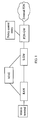
FIG. 1 shows an evolved packet system (EPS) network according to an embodiment of the present invention. The EPS network includes a mobile terminal, a radio access network, a serving gateway (S-GW), a mobility management element, a packet data network gateway (PDN-GW or P-GW), and a policy control entity. When the mobility management element is a mobility management entity (MME), the signaling exchanged between the MME and the PDN-GW must cross the S-GW. If the mobility management element is a serving GPRS support node (SGSN), the SGSN may also send a tunnel management request to the S-GW and cooperate with the S-GW to process a tunnel management request initiated by the PDN-GW. - The embodiments of a tunnel management method, apparatus and system of the present invention will be described in detail with reference to the accompanying drawings.
- The first embodiment relates to a tunnel management method. As shown in
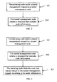
FIG. 2 , the method includes the following steps: - 201. In a communications system, when it is necessary to manage a user plane forwarding path, an initiating node sends a tunnel management request to a tunnel management node.
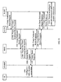
- 202. The tunnel management node receives the tunnel management request from the initiating node and performs appropriate processing, and sends a response that includes a cause value indicating success or failure of the tunnel management request to the initiating node. The response message also includes information of the node that causes failure of the tunnel management request.
- The embodiment provides another tunnel management method. As shown in
FIG. 3 , the method includes the following steps: - 301. In a communications system, when it is necessary to manage a user plane forwarding path, an initiating node sends a tunnel management request to a tunnel management node.
- 302. The tunnel management node receives the tunnel management request from the initiating node and performs appropriate processing, and sends a response that includes a cause value indicating success or failure of the tunnel management request to the initiating node. The response message returned after processing failure also includes node information.
- 303. The initiating node finds the node that causes the tunnel management request failure according to the node information. In practice, reasons of failure are varied and therefore different processing is required after the node that causes the tunnel management request failure is located. The subsequent embodiments of the present invention describe the processing with regard to four of the error causes.
- According to the tunnel management method shown in
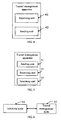
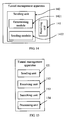
FIG. 2 , the embodiment of the present invention provides a tunnel management apparatus. As shown inFIG. 4 , the apparatus includes a receivingunit 41 and a sendingunit 42. - The receiving
unit 41 is configured to receive the tunnel management request from the initiating node. When the processing of the tunnel management request fails, the sendingunit 42 is configured to send a response that includes node information to the initiating node. The node information is information of the node that causes the tunnel management request failure so that the initiating node can find the node that causes the tunnel management request failure according to the node information. - According to the tunnel management method shown in
FIG. 3 , the embodiment of the present invention provides a tunnel management apparatus. As shown inFIG. 5 , the apparatus includes a sendingunit 51, a receivingunit 52, and a searchingunit 53. - The sending
unit 51 is configured to send a tunnel management request to a tunnel management node, which returns a response that includes node information to the apparatus after processing the tunnel management request. The receivingunit 52 is configured to receive the response that includes node information returned by the tunnel management node. The searchingnode 53 is configured to find the node that causes the tunnel management request failure according to the node information. - The embodiment also provides a communications system. As shown in
FIG. 6 , the communications system includes an initiatingnode 61 and atunnel management node 62. In the communications system, when it is necessary to manage a user plane forwarding path, the initiatingnode 61 is configured to send a tunnel management request; thetunnel management node 62 is configured to receive the tunnel management request from the initiatingnode 61 and return a response that includes node information to the initiatingnode 61; the initiatingnode 61 is further configured to find the node that causes the tunnel management request failure according to the node information and perform processing accordingly afterwards, for example, select an effective error check direction or select a new node. Specifically, the error check is: checking whether the error is caused by the local equipment implementation when the error cause included in the received response is an information element (IE) related error with the value such as "IE missing" or "IE decodes error" and checking the equipment implementation of the error node indicated in the response message when the local equipment implementation is correct. This helps the node to locate the error cause quickly and thus assures the correct proceeding of the subsequent procedure. - The embodiment of the present invention determines whether the failure of a tunnel management request is caused by the tunnel management node or a remote node according to the node information so that the initiating node can process the tunnel management request failure more conveniently, more efficiently and more quickly.
- The application environment of the embodiment is an EPS network.
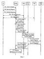
FIG. 7 shows the processing of the network in a attach procedure in EPS network, especially when a tunnel management request fails. The method includes the following steps: - 701. A user equipment (UE) sends an Attach Request to the MME.
- 702. The MME sends an Identity Request to the UE.
- 703. The UE sends an Identity Response to the MME according to the Identity Request of the MME.
- In the embodiment, steps 702 and 703 are optional.
- 704. The MME and a home subscriber server (HSS) complete authentication of the UE together.
- 705. The MME and an equipment identity register (EIR) complete the IMEI check of the UE together.
- 706. The MME sends an Update Location request to the HSS.
- 707. The HSS sends an Insert Subscriber Data to the MME.
- 708. The MME returns an Insert Subscriber Data ACK to the HSS.
- 709. The HSS returns an Update Location ACK to the MME after the MME acknowledges the subscriber data.
- 710. After the MME receives the location update information, the MME sends a Create Default Bearer Request to the S-GW to create a bearer.
- 711. As a tunnel management node, the S-GW processes the Create Default Bearer Request sent by the MME. If the S-GW processes the Create Default Bearer Request successfully, steps 712, 713, 714, 716 and subsequent steps are performed; otherwise,
step 715 and subsequent steps are performed. - 712. The S-GW sends the Create Default Bearer Request to the P-GW.
- 713. The P-GW processes the Create Default Bearer Request sent from the S-GW and sends a Create Default Bearer Response to the S-GW. The response message includes a cause value indicating whether the processing of the Create Default Bearer Request is successful or unsuccessful, and if unsuccessful, indicating the reason of the processing failure.
- 714. After the S-GW receives the response from the P-GW, the S-GW returns a Create Default Bearer Response to the MME, indicating whether the processing of the Create Default Bearer Request is successful or unsuccessful with a cause value, and when the response received from the P-GW indicates processing failure, the response returned to the MME includes node information of the P-GW, identifying the node that causes the Create Default Bearer Request failure. The node information may be indicated by a field in the cause of the failure of the tunnel management request, or an IE in the response message.
- 715. When the S-GW fails to process the Create Default Bearer Request, the S-GW sends a Create Default Bearer Response to the MME, indicating the reason of the Create Default Bearer Request failure with a cause value. The response message includes node information of the S-GW, identifying the node that causes the Create Default Bearer Request failure. The node information may be indicated by a field in the error cause of the tunnel management request, or an IE in the response message.
- To enable the MME to obtain more information about the Create Default Bearer Request failure, the response returned in the step may further include additional location information to identify the reason of the Create Default Bearer Request failure.
716. After the MME receives the Create Default Bearer Response, the MME performs processing according to the node information and additional location information included in the response message. As shown inFIG. 8 , the processing of the MME includes the following steps: - 801. The MME decodes the received Create Default Bearer Response to obtain the node information and additional location information included in the response.
- 802. The MME finds the node that causes the Create Default Bearer Request failure according to the obtained node information.
- 803. The MME analyzes the reason of the Create Default Bearer Request failure according to the cause value. If the reason of the request failure is resource insufficiency or equipment failure, the process proceeds to step 804. The resource insufficiency includes bandwidth insufficiency and memory insufficiency. If the reason of the request failure is IE missing or IE decodes error, for example, an IE in the Create Default Bearer Request is missing or a correct IE is not decoded,
step 807 is performed. - 804. The MME determines whether the node that causes the Create Default Bearer Request failure is the S-GW or P-GW. If the node is the S-GW,
step 805 is performed; if it is the P-GW,step 806 is performed. - 805. The MME selects a new S-GW without changing the P-GW and continues with another Create Default Bearer Request.
- 806. The MME selects a new P-GW without changing the S-GW and continues with another Create Default Bearer Request.
- 807. The MME locates the missing IE or the incorrectly decoded IE according to the additional location information. An operator may first check whether an error has occurred in the MME, for example, whether IEs in the sent request message are correct. If the IEs are incorrect, the operator can check the MME so that the MME sends the correct Create Default Bearer Request in the next attach procedure. If the IEs are correct, the operator can check whether an error has occurred in the node that causes the Create Default Bearer Request failure.
- In practice, because the reasons of the Create Default Bearer Request failure are varied, the MME needs to perform different processing accordingly.
- The interface protocol between S-GW and P-GW in the embodiment communicate is the GPRS Tunneling Protocol (GTP). In practice, the S-GW and P-GW may communicate over the Proxy Mobile IP Protocol (PMIP), in which
case step 712 and step 713 above are modified as follows: - 712'. The S-GW sends a Proxy Binding Update request to the P-GW.
- 713'. The P-GW processes the Proxy Binding Update request from the S-GW and sends a response to the S-GW if the P-GW fails to process the Proxy Binding Update request. The response is in particular a Proxy Binding ACK, which includes a cause value indicating failure of the processing.
- With the node information included in the response returned by the S-GW, the MME can know the node that causes the Create Default Bearer Request failure. When the Create Default Bearer Request fails, the MME can adjust the node that causes the failure in time so that the subsequent procedure is performed correctly.
- The embodiment is applicable to a tracking area update procedure. As shown in
FIG. 9 , when a tunnel management request fails, the processing on the network side includes the following steps: - 901. A UE sends a Tracking Area Update Request to an evolved NodeB (eNodeB) and the eNodeB sends the Tracking Area Update Request to a new MME.
- 902. The new MME receives the Tracking Area Update Request and obtains a context from the old MME.
- 903. The new MME decides whether to select a new S-GW according to the user location information sent from the eNodeB. If the new MME decides not to select a new S-GW, the new MME sends an Update Bearer Request to the old S-GW.
- 904. As a tunnel management node, the old S-GW processes the Update Bearer Request sent from the new MME. If the old S-GW processes the Update Bearer Request successfully, steps 905, 906, 907, 909 and subsequent steps are performed; otherwise,
step 908 and subsequent steps are performed. - 905. The old S-GW sends an Update Bearer Request to the P-GW.
- 906. The P-GW processes the Update Bearer Request from the old S-GW and sends an Update Bearer Response to the old S-GW. The response message includes a cause value indicating whether the processing of the Update Bearer Request is successful or unsuccessful, and if unsuccessful, indicating the reason of the processing failure.
- 907. The old S-GW receives the Update Bearer Response from the P-GW and sends an Update Bearer Response to the new MME, indicating whether the processing of the Update Bearer Request is successful or unsuccessful with a cause value, and if the cause value included in the Update Bearer Response returned by the P-GW indicates processing failure, the response returned to the new MME includes the node information of the P-GW to identity the node that causes the Update Bearer Request failure. The node information may be indicated by a field in the cause of the failure of the tunnel management request, or an IE in the response message.
- To enable the new MME to obtain more information about the Update Bearer Request failure, the response returned in the step may further include additional location information to identify the reason of the Update Bearer Request failure.
- 908. When the old S-GW fails to process the Update Bearer Request, the old S-GW sends to the new MME an Update Bearer Response, which indicates the reason of the Update Bearer Request failure with a cause value and includes node information of the old S-GW identifying the node that causes the Update Bearer Request failure.
- 909. The new MME receives the Update Bearer Response and performs processing according to the node information in the response message. For example, the new MME first checks for errors of the local node in the case of an IE related error and then the node causing occurrence of the error checks for errors.
- In the embodiment, only the MME is updated in the tracking area update procedure and sometimes the S-GW is also updated. When it is necessary to update the S-GW, the processing is similar to that shown in
FIG. 9 and the only difference is that the functions completed by the old S-GW are completed by the new S-GW, as shown by the broken lines. - The step where the new MME obtains a context is the same as
steps - In practice, procedures like those in the second and third embodiments are adopted in many scenarios such as routing area update and PDN connectivity to implement the failure prompt of tunnel management requests.
- In routing area update scenarios, with respect to a routing area update request from a UE, the following two cases may exist:
- In the first case, the S-GW changes. In this case, the new SGSN acts as the initiating node of the Create Bearer Request and the new S-GW acts as the tunnel management node of the Create Bearer Request, and the P-GW acts as the remote node. The procedure is shown by the solid lines in
FIG. 10 . - The UE sends a Routing Area Update Request to the new SGSN. The new SGSN obtains a context from the old SGSN and afterwards sends a Create Bearer Request to the new S-GW. If the new S-GW processes the Create Bearer Request correctly, the new S-GW sends an Update Bearer Request to the P-GW; otherwise, the new S-GW sends to the new SGSN a Create Bearer Response which includes node information of the new S-GW, indicating that the bearer creation failure is caused by the new S-GW. After processing the Update Bearer Request, the P-GW returns to the new S-GW an Update Bearer Response which indicates processing success or failure with a cause value. If the P-GW fails to process the Update Bearer Request, the P-GW returns to the new S-GW an Update Bearer Response that indicates failure. The new S-GW also sends a Create Bearer Response to the new SGSN and when the message returned by the P-GW indicates processing failure, the message returned to the new SGSN includes node information of the P-GW, indicating that the bearer creation failure is caused by the P-GW.
- In the second case, the S-GW does not change. In this case, the old SGSN acts as the initiating node of the Routing Area Update Request, the old S-GW acts as the tunnel management node of the Routing Area Update Request, and the P-GW acts as the remote node. The procedure is shown by the broken lines in
FIG. 10 . - The UE sends a Routing Area Update Request to the old SGSN. The old SGSN sends an Update Bearer Request to the old S-GW. If the old S-GW processes the Update Bearer Request correctly, the old S-GW sends an Update Bearer Request to the P-GW; otherwise, the old S-GW returns to the old SGSN an Update Bearer Response, which includes node information of the old S-GW, indicating that the bearer update failure is caused by the old S-GW. After processing the Update Bearer Request, the P-GW returns to the old S-GW an Update Bearer Response which indicates processing success or failure with a cause value. If the P-GW fails to process the Update Bearer Request, the P-GW returns to the old S-GW an Update Bearer Response that indicates failure. The old S-GW also sends an Update Bearer Response to the old SGSN and when the message returned by the P-GW indicates processing failure, the message returned to the old SGSN includes node information of the P-GW, indicating that the bearer update failure is caused by the P-GW.
- From the above description, it is known that the method in the embodiment can indicate the node that causes failure of tracking area update or routing area update in a tracking area update or routing area update procedure so that the node causing the tracking area update or routing area update failure is adjusted in time and that the subsequent procedure proceeds correctly.
- The scenario of the fourth embodiment is the handover from an evolved UMTS territorial radio access network (E-UTRAN) to a UMTS territorial radio access network (UTRAN). As shown in
FIG. 11 , when a tunnel management request fails, the processing of the network includes the following steps: - 1101. A UE creates a forwarding tunnel for downlink service packets with the target SGSN of a radio access network and sends the serving radio network subsystem (SRNS) context to the target SGSN.
- 1102. The target SGSN receives the SRNS context and sends an Update Bearer Request to the target S-GW.
- 1103. As a tunnel management node, the target S-GW processes the Update Bearer Request sent from the target SGSN. If the target S-GW processes the Update Bearer Request successfully, steps 1104, 1105, 1107 and subsequent steps are performed; otherwise,
steps - 1104. The target S-GW sends an Update Bearer Request to the P-GW.
- 1105. The P-GW processes the Update Bearer Request sent from the target SGSN and returns to the target S-GW an Update Bearer Response, which includes a cause value indicating processing success or failure. When the P-GW fails to process the Update Bearer Request, the P-GW returns to the target S-GW an Update Bearer Response that includes an error cause and node information of the P-GW.
- 1106. When the target S-GW fails to process the Update Bearer Request, the target S-GW sends to the target SGSN an Update Bearer Response, which indicates the reason of the Update Bearer Request failure with a cause value and includes node information of the target S-GW identifying the node that causes the Update Bearer Request failure.
- 1107. The target S-GW receives the response from the P-GW and sends to the target SGSN an Update Bearer Response, which includes a cause value indicating whether the processing of the Update Bearer Request is successful or unsuccessful. If the cause value included in the response received from the P-GW indicates processing failure, the target S-GW sends the node information in the response from the P-GW transparently to the target SGSN. The node information may be indicated by a field in the cause of the failure of the tunnel management request or an IE in the response message.
- To enable the target SGSN to obtain more information about the Update Bearer Request failure, the response returned in the step may further include additional location information to identify the specific reason of the Update Bearer Request failure.
- 1108. After the target SGSN receives the Update Bearer Response, the target SGSN performs processing according to the node information and additional location information included in the response message. In the case of an IE related error, the target SGSN first checks for errors in the local node. After it is determined that the processing of the SGSN is correct, the node that causes occurrence of the error checks for errors so that the next procedure can proceed correctly. In the case of resource insufficiency, if the node information indicates an error of the target S-GW, the target SGSN may select a new S-GW and initiate a tunnel management procedure.
- From the above description, it is known that the method in the embodiment of the present invention indicates whether the node that causes a bearer update failure is the target S-GW or P-GW during the handover from an E-UTRAN to a UTRAN, so that the target SGSN can adjust the node causing the bearer update failure in time and that the subsequent procedure will proceed correctly.
- The scenario of the fifth embodiment is a PDN connectivity procedure. As shown in
FIG. 12 , when the procedure fails, the method includes the following steps: - 1201. A UE sends a PDN Connectivity Request to the MME.
- 1202. The MME receives the PDN Connectivity Request and sends a Create Default Bearer Request to the S-GW to create a bearer.
- 1203. As a tunnel management node, the S-GW processes the Create Default Bearer Request. If the S-GW processes the Create Default Bearer Request successfully,
step 1204 tosteps 1210 and 1212 are performed; otherwise,steps 1211 and 1212 are performed. - 1204. The S-GW sends the Create Default Bearer Request to the P-GW.
- 1205. As a tunnel management node, the P-GW processes the Create Default Bearer Request. If the P-GW processes the Create Default Bearer Request successfully, step 1206 to
steps 1208, 1210 and 1212 are performed; otherwise, steps 1209, 1210 and 1212 are performed. - 1206. The P-GW creates an IP Connectivity Access Network (IP-CAN) session with a Policy and Charging Rules Function (PCRF).
- 1207. The PCRF sends to the P-GW a response message which includes a cause value indicating whether the IP-CAN session is created successfully or unsuccessfully.
- 1208. The P-GW receives the response from the PCRF and returns to the S-GW a Create Default Bearer Response, which includes a cause value indicating whether the processing of the Create Default Bearer Request succeeds or fails. When the cause value in the response received from the PCRF indicates processing failure, the response returned to the S-GW includes node information of the PCRF, identifying the node that causes the Create Default Bearer Request failure.
- 1209. The P-GW sends to the S-GW a Create Default Bearer Response, which includes a cause value indicating that the Create Default Bearer Request fails and node information of the P-GW, identifying the node that causes the Create Default Bearer Request failure.
- The node information may be indicated by a field in the cause of failure of the tunnel management request, or an IE in the response message.
- To enable the S-GW to obtain more information about the Create Default Bearer Request failure, the response returned in steps 1208 and 1209 may further include additional location information to identify the reason of the Create Default Bearer Request failure. The additional location information may be indicated by a field in the cause of the failure of the tunnel management request, or an IE in the response message.
- 1210. The S-GW sends to the MME a Create Default Bearer Response, which includes a cause value indicating that the Create Default Bearer Request fails and node information, identifying the node that causes the Create Default Bearer Request failure. The node information is that included in the response received from the P-GW.
- The node information may be indicated by a field in the cause of the failure of the tunnel management request, or an IE in the response message. To enable the MME to obtain more information about the Create Default Bearer Request failure, the response returned in the step may further include additional location information to identify the specific reason of the Create Default Bearer Request failure. The additional location information may be the additional location information included in the response received by the S-GW. The additional location information may also be indicated by a field in the cause of the failure of the tunnel management request, or an IE in the response message.
- 1211. The S-GW sends to the MME a Create Default Bearer Response, which includes a cause value indicating that the Create Default Bearer Request fails and node information of the S-GW, identifying the node that causes the Create Default Bearer Request failure.
- 1212. After the MME receives the Create Default Bearer Response, the MME performs processing according to the node information and additional location information included in the response message. In the case of an IE related error, the MME first checks for errors in the local node. After it is determined that the processing of the local node is correct, the node that causes occurrence of the error checks for errors so that the next procedure can proceed correctly. In the case of resource insufficiency, if the node information indicates an error of the P-GW, the MME may select a new P-GW and initiate a new tunnel management procedure. The specific error cause can be known from the additional location information, for example, which IE is lost and which IE is decoded incorrectly.
- From the above description, it is known that in the PDN connectivity procedure, the method in the embodiment of the present invention can indicate whether the node causing the PDN connectivity failure is the S-GW, P-GW, or PCRF, so that the MME can adjust the node causing the PDN connectivity failure and that the subsequent procedure can proceed correctly.
- The scenario of the sixth embodiment is the bearer creation initiated by the P-GW. As shown in
FIG. 13 , the method for indicating the bearer creation failure includes the following steps: - 1301. The P-GW sends a Create Dedicated Bearer Request to the S-GW.
- 1302. As a tunnel management node, the S-GW processes the Create Dedicated Bearer Request. If the S-GW processes the Create Dedicated Bearer Request successfully,
step 1303 to step 1310 and step 1312 are performed; otherwise, steps 1311 and 1312 are performed. - 1303. The S-GW sends the Create Dedicated Bearer Request to the MME.
- 1304. After the MME receives the Create Dedicated Bearer Request, the MME processes the Create Dedicated Bearer Request. If the MME processes the Create Dedicated Bearer Request successfully,
step 1305 tosteps - 1305. The MME sends a Create Bearer Request to the eNodeB of the UE to create a bearer.
- 1306. The eNodeB configures a Radio Resource Connection (RRC) with the UE.
- 1307. The eNodeB returns a Create Bearer Response to the MME. If the RRC configuration fails, or the bearer between the eNodeB and the S-GW fails, the response returned by the eNodeB to the MME includes a failure cause value.
- 1308. The MME returns to the S-GW a Create Dedicated Bearer Response, which includes a cause value of the dedicated bearer creation failure and node information of the eNodeB, indicating that the dedicated bearer creation failure is caused by the eNodeB. The node information may be indicated by a field in the cause of failure of the bearer creation, or an IE in the response message.
- 1309. The MME returns to the S-GW a Create Dedicated Bearer Response, which includes a cause value of the dedicated bearer creation failure and node information of the MME, indicating that the dedicated bearer creation failure is caused by the MME. The node information may be indicated by a field in the cause of the failure of the bearer creation, or an IE in the response message.
- 1310. The S-GW sends to the P-GW a Create Dedicated Bearer Response, which includes a cause value indicating that the Create Dedicated Bearer Request fails and node information, identifying the node that causes the Create Dedicated Bearer Request failure. The node information is included in the response message sending from the MME. The node information may be indicated by a field in the cause of the failure of the Create Dedicated Bearer Request, or an IE in the response message.
- 1311. The S-GW sends to the P-GW a Create Dedicated Bearer Response, which includes a cause value indicating that the Create Dedicated Bearer Request fails and node information of the S-GW, identifying the node that causes the Create Dedicated Bearer Request failure.
- To enable the P-GW to obtain more information about the Create Dedicated Bearer Request failure, the response returned in the step may further include additional location information to identify the reason of the Create Dedicated Bearer Request failure. The additional location information may also be indicated by a field in the cause of the failure of the tunnel management request, or an IE in the response message.
- 1312. After the P-GW receives the Create Dedicated Bearer Response, the P-GW performs processing according to the node information and additional location information included in the response message. In the case of an IE related error, the P-GW first checks for errors in the local node. After it is determined that the processing of the local node is correct, the node that causes occurrence of the error checks for errors so that the next procedure can proceed correctly.
- From the above description, it is known that in the dedicated bearer creation procedure, the method in the embodiment of the present invention can indicate whether the node causing the dedicated bearer creation failure is the S-GW, MME, or eNodeB, so that the P-GW can adjust the node causing the dedicated bearer creation failure and that the subsequent procedure can proceed correctly.
- According to the second to sixth embodiments, the embodiment of the present invention provides a tunnel management apparatus. As shown in
FIG. 14 , the apparatus includes a receivingunit 141 and a sendingunit 142. - The receiving
unit 141 is configured to receive a tunnel management request from an initiating node; when the tunnel management request of the initiating node is processed unsuccessfully, the sendingunit 142 is configured to send to the initiating node a response, which includes node information of the node that causes the tunnel management request failure. - The node that causes the tunnel management request failure may be the local node or a remote node. When the node causing the failure is the local node, to assure correct processing of the tunnel management apparatus, the sending
unit 142 includes a determiningmodule 1421 and asending module 1422. - The determining
module 1421 is configured to determine whether the local node is able to complete the tunnel management request. The sendingmodule 1422 is configured to send to the initiating node a response message which includes a cause value of failure of the tunnel management request and local node information when the determiningmodule 1421 determines that the local node is unable to complete the tunnel management request, where the local node information is the node information of the node that causes the tunnel management request failure. - When the node causing the tunnel management request failure is a remote node, two cases exist:
- In the first case, the node that causes the tunnel management request failure is directly connected to the local node. When the local node processes the tunnel management request correctly, the sending
unit 142 is further configured to send the tunnel management request to the remote node. After the remote node processes the tunnel management request, the remote node returns a tunnel management response to the local node. The response message includes a cause value indicating whether the processing is successful or unsuccessful. The receivingunit 141 of the local node is also configured to receive the response from the remote node. When the processing of the remote node is unsuccessful, the response includes a cause value of the tunnel management request failure. Therefore, the response sent by the sendingunit 142 to the initiating node includes the cause value of the tunnel management request failure and information of the remote node. This means the response indicates that the remote node information is the node information of the node that causes the tunnel management request failure. - In the second case, the node that causes the tunnel management request failure is a remote node, which is connected to the local node via another remote node. In this case, the sending
unit 142 is further configured to send the tunnel management request to the other remote node. The response returned by the other remote node to the local node includes the cause value of the tunnel management request failure and node information which is the information of the remote node. The receivingunit 141 is further configured to receive the response from the other remote node. The response includes the cause value of the tunnel management request failure and node information. The sendingunit 142 sends to the initiating node a response that includes the failure cause value and the received node information. This means that the local node transmits the received cause value of the tunnel management request failure and the node information transparently to the initiating node. - To better distinguish the specific reason of the tunnel management request failure, the response received by the receiving
unit 141 in the embodiment may also include additional location information, identifying the specific reason of the tunnel management request failure. For example, the additional location information may indicate which IE is missing or incorrectly decoded and which mandatory IE is missing. Likewise, the response sent by the sendingunit 142 in the embodiment to the initiating node may also include the additional location information so that the initiating node can find the correct failure cause. - In practice, the tunnel management apparatus in the embodiment of the present invention may be configured in many network devices, such as the S-GW, P-GW, MME, and SGSN.
- According to the tunnel management method shown in
FIG. 8 in the second embodiment, the embodiment of the present invention provides another tunnel management apparatus. As shown inFIG. 15 , the apparatus includes a sendingunit 151, a receivingunit 152, and a searchingunit 153. - The sending
unit 151 is configured to send a tunnel management request to the tunnel management node. After the tunnel management node processes the tunnel management request, the tunnel management node returns a tunnel management response to the apparatus. If the processing is unsuccessful, the response returned to the apparatus includes node information and additional location information. The node information identifies the node that causes the tunnel management request failure. The additional location information identifies the specific reason of the tunnel management request failure. The receivingunit 152 is configured to receive the response that includes node information returned by the tunnel management node. The searchingunit 153 is configured to find the node that causes the tunnel management request failure according to the node information and find the specific reason of the tunnel management request failure according to the additional location information to facilitate the error checking. - To guarantee that the apparatus in the embodiment performs error checking correctly, the tunnel management apparatus further includes a
processing unit 154. Theprocessing unit 154 is configured to select a new node to replace the node that causes the tunnel management request failure when the cause of the tunnel management request failure is resource insufficiency or equipment failure; or theprocessing unit 154 is configured to check for errors of the local node or instruct the node that causes the tunnel management request failure to check for errors when the cause of the tunnel management request failure is IE missing or IE decoded error. - If the network devices are defined as an initiating node, an intermediate node and a remote node, the function of the tunnel management apparatus shown in
FIG. 14 to determine whether the local device is able to process the request can be configured on the intermediate node or the remote node; the function of sending or transparently transmitting the error node indication to the initiating node after receiving the response from the remote node can only be implemented on the intermediate node. The tunnel management apparatus shown inFIG. 15 is only configured on the initiating node. Depending on the specific type of tunnel management request, the initiating node may be an MME, or a P-GW, or an SGSN. - In the embodiment, the response returned by the intermediate node to the initiating node includes node information to enable the initiating node to find the node that causes the tunnel management request failure and make node adjustment accordingly, so that the subsequent procedure proceeds correctly.
- The eighth embodiment provides a communications system. As shown in
FIG. 16 , the communications system includes an initiatingnode 161 and atunnel management node 162. When it is necessary to manage a user plane forwarding path, the initiatingnode 161 is configured to send a tunnel management request to thetunnel management node 162. Thetunnel management node 162 is configured to receive the tunnel management request from the initiatingnode 161 and determine whether the tunnel management node is able to complete the tunnel management request. If thetunnel management node 162 is unable to complete the tunnel management request, thetunnel management node 162 sends to the initiating node 161 a response which includes the cause value of the tunnel management request failure and information of the tunnel management node, indicating that the tunnel management node is the node that causes the tunnel management request failure. The initiatingnode 161 is further configured to find the node that causes the tunnel management request failure according to the node information in the response returned by the tunnel management node and perform related error checking. - The above communications system generally relates to the communication between two network devices, for example, between MME and S-GW and between S-GW and P-GW.
- When a third network device exists in the communications system, the communications system in the embodiment further includes a
remote node 163. - When the
tunnel management node 162 is able to process the tunnel management request correctly, thetunnel management node 162 sends the tunnel management request to theremote node 163, which causes failure of the tunnel management request due to a certain reason, such as a local node error. Theremote node 163 is then configured to return to the tunnel management node 162 a response which includes the cause value of the tunnel management request failure. In this case, thetunnel management node 162 is further configured to send to the initiating node 161 a response that includes the cause value of the tunnel management request failure and information of the remote node, indicating that the remote node is the node causing the tunnel management request failure. - If the remote node is connected to a connection processing device and the tunnel management request from the initiating node needs to be processed by the connection processing device, and if the device that ultimately causes the tunnel management request failure is the connection processing device, the processing of the communications system is as follows:
- When the
tunnel management node 162 is able to process the tunnel management request, thetunnel management node 162 sends the tunnel management request to theremote node 163. Because theremote node 163 processes the request correctly, the tunnel remote node sends the request to the connection processing device. The connection processing device fails to process the request and returns a failure cause value only to the remote node. Therefore, the response returned by theremote node 163 to thetunnel management node 162 includes the cause value of the tunnel management request failure and node information which is node information of the connection processing device. In this case, thetunnel management node 162 is further configured to send to the initiating node 161 a response that includes the cause value of the tunnel management request failure and the received node information. The received node information matches the node that causes the tunnel management request failure, that is, the connection processing device. In the embodiment, thetunnel management node 162 transmits the cause value of the tunnel management request failure and the received node information transparently to the initiating node. - The embodiment is applicable to a communications system with respect to various possible failure causes during the management of a user plane forwarding path and indicates the cause to the initiating node so that the initiating node performs appropriate processing.
- Because the response received by the initiating node includes node information and the initiating node can find the node causing the tunnel management request failure according to the node information, the initiating node will be able to distinguish whether the tunnel management request failure is caused by the tunnel management node or the remote node, even if the tunnel management node further sends the tunnel management request to the remote node. Thus, the initiating node can process the tunnel management request failure more conveniently, more efficiently, and more quickly.
- Through the descriptions of the preceding embodiments, those skilled in the art may understand that the present invention may be implemented by hardware only or by software and a necessary universal hardware platform. However, in most cases, using software and a necessary universal hardware platform are preferred. Based on such understandings, all or part of the technical solution under the present invention that makes contributions to the prior art may be essentially embodied in the form of a software product. The software product may be stored in a computer readable storage medium, such as a hard disk, a compact disk read-only memory (CD-ROM), and a floppy disk. The software product includes a number of instructions that enable a computer device (personal computer, server, or network device) to execute the methods provided in the embodiments of the present invention.
- Although the invention has been described through some exemplary embodiments, the invention is not limited to such embodiments.
Claims (18)
- A method of determining a node that causes failure in a tunnel management procedure, comprising
receiving a tunnel management request from an initiating node;
sending a response message to the initiating node, wherein the response message comprises a cause value indicating whether the tunnel management request is successful or unsuccessful, and when unsuccessful indicates a reason, characterized in that:in the response message there is included information of a node that causes failure of the tunnel management request when the tunnel management request fails, the information enabling correct determination of which node out of the different nodes in the tunnel management procedure caused the failure of the tunnel management request. - The method of claim 1, further comprising:determining whether a local node is able to complete the tunnel management request; andif the local node is unable to complete the tunnel management request, the node information comprised in the response message is information of the local node.
- The method of claim 1, further comprising:sending the tunnel management request to a remote node; andreceiving from the remote node a response message, which comprises a cause value of tunnel management request failure; whereinthe step of sending to the initiating node a response message comprises sending to the initiating node a response message that comprises the cause value of tunnel management request failure and information of the remote node, wherein the information of the remote node is information of the node that causes the tunnel management request failure.
- The method of claim 1, further comprising:sending the tunnel management request to a remote node; andreceiving from the remote node a response message, which comprises a cause value of tunnel management request failure and node information;the step of sending to the initiating node a response message that comprises node information comprises: sending to the initiating node a response message that comprises the cause value of tunnel management request failure and the received node information, wherein the received node information is information of the node that causes the tunnel management request failure.
- The method of claim 3 or 4, wherein:the response message received from the remote node comprises additional location information for locating a missing information element, IE, or an incorrectly decoded IE, wherein the additional location information identifies a specific reason of the tunnel management request failure; andthe response message sent to the initiating node comprises the additional location information.
- A method of determining a node that causes failure in a tunnel management procedure, comprising
sending a tunnel management request to a tunnel management node;
receiving from the tunnel management node a response message, wherein the response message comprises a cause value indicating whether the tunnel management request is successful or unsuccessful, and when unsuccessful indicates a reason, characterized in that:in the response message there is included information of a node that causes failure of the tunnel management request when the tunnel management request fails, the information enabling correct determination of which node out of the different nodes in the tunnel management procedure caused the failure of the tunnel management request; andfinding the node that causes failure of the tunnel management request according to the node information. - The method of claim 6, further comprising:if the cause of the tunnel management request failure is resource insufficiency or equipment failure, selecting a new node to replace the node that causes failure of the tunnel management request; andif the cause of the tunnel management request failure is Information Element (IE) missing or IE decode error, locating a specific IE that is missing or incorrectly decoded according to additional location information.
- A tunnel management procedure apparatus, comprising
a receiving unit (141), configured to receive a tunnel management request from an initiating node;
a sending unit (142), configured to send to the initiating node a response message, which comprises a cause value indicating whether the tunnel management request is successful or unsuccessful, and when unsuccessful indicates a reason, characterized in that the sending unit is further configured to include in the response message information of a node that causes failure of the tunnel management request when the tunnel management request fails, the information enabling correct determination of which node out of different nodes in the tunnel management procedure caused the failure of the tunnel management request. - The apparatus of claim 8, wherein the sending unit (142) comprises:a determining module (1421), configured to determine whether a local node is able to complete the tunnel management request; anda sending module (1422), configured to send to the initiating node a response message which comprises a cause value of tunnel management request failure and information of the local node when the local node is unable to complete the tunnel management request, wherein the local node information is information of the node that causes failure of the tunnel management request.
- The apparatus of claim 8, wherein:the sending unit (142) is further configured to send the tunnel management request to a remote node;the receiving unit (141) is further configured to receive from the remote node a response message, which comprises a cause value of tunnel management request failure; andwherein the information of a node is information of the remote node that causes the tunnel management request failure.
- The apparatus of claim 8, wherein:the sending unit (142) is further configured to send the tunnel management request to a remote node;the receiving unit (141) is further configured to receive from the remote node a response message, which comprises a cause value of tunnel management request failure and node information; andthe sending unit (142) sends to the initiating node a response message which comprises the cause value of tunnel management request failure and the received node information, wherein the received node information is node information of the node that causes the tunnel management request failure.
- The apparatus of claim 10 or 11, wherein:the response message received from the remote node comprises additional location information for locating a missing information element, IE, or an incorrectly decoded IE, which identifies a specific reason of the tunnel management request failure; andthe response message sent by the sending unit to the initiating node comprises the additional location information.
- A tunnel management procedure apparatus, comprising
a sending unit (151), configured to send a tunnel management request to a tunnel management node;
a receiving unit (152), configured to receive a response message from a tunnel management node that comprises a cause value indicating whether the tunnel management is successful or unsuccessful, and when unsuccessful indicates a reason, characterized in that
the response message includes node information, being information of a node that causes failure of the tunnel management request when the tunnel management request fails; and the apparatus further comprises
a searching unit (153), configured to find from the node information and correctly determine which node, out of different nodes in the tunnel management procedure, caused the failure of the tunnel management request. - The apparatus of claim 13, further comprising:a processing unit (154), configured to select a new node to replace the node that causes failure of the tunnel management request when the cause of the tunnel management request failure is resource insufficiency or equipment failure; or configured to locate a specific Information Element (IE) that is missing or incorrectly decoded when the cause of the tunnel management request failure is IE missing or IE decode error.
- A communications system, comprising:an initiating node (161), configured to send a tunnel management request;a tunnel management node (162), configured to receive the tunnel management request from the initiating node (161) and return a response to the initiating node (161), wherein the response comprises a cause value indicating whether the tunnel management request is successful or unsuccessful, and when unsuccessful indicates a reason, characterized in that:the response includes node information, being information of a node that causes failure of the tunnel management request when the tunnel management request fails; andthe initiating node (161) is further configured to find from the node information and correctly determine which node out of different nodes in the tunnel management procedure caused failure of the tunnel management request
- The system of claim 15, wherein:the tunnel management node (162) is further configured to determine whether the tunnel management node (162) is able to complete the tunnel management request; andif the tunnel management node (162) is unable to complete the tunnel management request, the tunnel management node (162) is further configured to send to the initiating node (161) a response message, which comprises a cause value of the tunnel management request failure and information of the tunnel management node, wherein the information of the tunnel management node is the node that causes failure of the tunnel management request.
- The system of claim 15, further comprising a remote node (163), wherein:the tunnel management node (162) is further configured to send the tunnel management request to the remote node (163);the remote node (163) is configured to return to the tunnel management node (162) a response message, which comprises a cause value of tunnel management request failure; andthe tunnel management node (162) is further configured to send to the initiating node (161) a response message which comprises the cause value of tunnel management request failure and information of the remote node, wherein the information of the remote node is the node that causes failure of the tunnel management request.
- The system of claim 15, further comprising a remote node (163), wherein:the tunnel management node (162) is configured to send the tunnel management request to the remote node (163);the remote node (163) is configured to return to the tunnel management node (162) a response message, which comprises a cause value of tunnel management request failure and node information; andthe tunnel management node (162) is further configured to send to the initiating node (161) a response message which comprises the cause value of tunnel management request failure and the received node information, wherein the received node information is the node that causes failure of the tunnel management request.
Priority Applications (3)
| Application Number | Priority Date | Filing Date | Title |
|---|---|---|---|
| EP15192231.7A EP3010186B1 (en) | 2008-07-16 | 2009-05-26 | Tunnel management method, tunnel management apparatus, and communications system |
| PL09797378T PL2293502T3 (en) | 2008-07-16 | 2009-05-26 | Method, device and communication system for tunnelling management |
| EP12182102.9A EP2533481B1 (en) | 2008-07-16 | 2009-05-26 | Tunnel management method, tunnel management apparatus, and communications system |
Applications Claiming Priority (2)
| Application Number | Priority Date | Filing Date | Title |
|---|---|---|---|
| CN2008101324214A CN101631344B (en) | 2008-07-16 | 2008-07-16 | Method and device for managing tunnel and communication system |
| PCT/CN2009/072007 WO2010006531A1 (en) | 2008-07-16 | 2009-05-26 | Method, device and communication system for tunnelling management |
Related Child Applications (3)
| Application Number | Title | Priority Date | Filing Date |
|---|---|---|---|
| EP12182102.9A Division EP2533481B1 (en) | 2008-07-16 | 2009-05-26 | Tunnel management method, tunnel management apparatus, and communications system |
| EP15192231.7A Division EP3010186B1 (en) | 2008-07-16 | 2009-05-26 | Tunnel management method, tunnel management apparatus, and communications system |
| EP12182102.9 Division-Into | 2012-08-29 |
Publications (4)
| Publication Number | Publication Date |
|---|---|
| EP2293502A1 EP2293502A1 (en) | 2011-03-09 |
| EP2293502A4 EP2293502A4 (en) | 2011-08-10 |
| EP2293502B1 EP2293502B1 (en) | 2013-01-02 |
| EP2293502B9 true EP2293502B9 (en) | 2013-04-10 |
Family
ID=41550013
Family Applications (3)
| Application Number | Title | Priority Date | Filing Date |
|---|---|---|---|
| EP09797378.8A Active EP2293502B9 (en) | 2008-07-16 | 2009-05-26 | Method, device and communication system for tunnelling management |
| EP12182102.9A Active EP2533481B1 (en) | 2008-07-16 | 2009-05-26 | Tunnel management method, tunnel management apparatus, and communications system |
| EP15192231.7A Active EP3010186B1 (en) | 2008-07-16 | 2009-05-26 | Tunnel management method, tunnel management apparatus, and communications system |
Family Applications After (2)
| Application Number | Title | Priority Date | Filing Date |
|---|---|---|---|
| EP12182102.9A Active EP2533481B1 (en) | 2008-07-16 | 2009-05-26 | Tunnel management method, tunnel management apparatus, and communications system |
| EP15192231.7A Active EP3010186B1 (en) | 2008-07-16 | 2009-05-26 | Tunnel management method, tunnel management apparatus, and communications system |
Country Status (7)
| Country | Link |
|---|---|
| US (4) | US8938640B2 (en) |
| EP (3) | EP2293502B9 (en) |
| JP (4) | JP5101734B2 (en) |
| CN (2) | CN101631344B (en) |
| ES (1) | ES2401758T3 (en) |
| PL (1) | PL2293502T3 (en) |
| WO (1) | WO2010006531A1 (en) |
Families Citing this family (12)
| Publication number | Priority date | Publication date | Assignee | Title |
|---|---|---|---|---|
| CN101631344B (en) | 2008-07-16 | 2011-10-05 | 华为技术有限公司 | Method and device for managing tunnel and communication system |
| FR2968156A1 (en) | 2010-11-30 | 2012-06-01 | France Telecom | COMMUNICATION TECHNIQUE BETWEEN USER EQUIPMENT AND A DATA NETWORK IN A COMMUNICATION NETWORK |
| FR2968155A1 (en) * | 2010-11-30 | 2012-06-01 | France Telecom | COMMUNICATION TECHNIQUE BETWEEN USER EQUIPMENT AND A DATA NETWORK IN A COMMUNICATION NETWORK |
| JP2014199980A (en) * | 2013-03-29 | 2014-10-23 | 株式会社Nttドコモ | PDN gateway device and mobile communication method |
| EP2978277B1 (en) * | 2013-05-20 | 2020-06-03 | Huawei Technologies Co., Ltd. | Data transmission methods and gateways |
| RU2640573C1 (en) * | 2013-12-30 | 2018-01-10 | Хуавей Текнолоджиз Ко., Лтд. | Method for correcting failure, data packet network, mobility control node and network system |
| EP3018941B1 (en) * | 2014-11-10 | 2021-08-18 | Vodafone GmbH | Establishing a bearer service in a telecommunications network |
| US10237795B2 (en) | 2015-10-11 | 2019-03-19 | Qualcomm Incorporated | Evolved packet data gateway (EPDG) reselection |
| CN106604295A (en) * | 2015-10-14 | 2017-04-26 | 大唐移动通信设备有限公司 | User service request method and mobility management entity device |
| EP3403429B1 (en) * | 2016-01-14 | 2020-04-22 | Telefonaktiebolaget LM Ericsson (PUBL) | Method and nodes for performing a tracking area update (tau) / routing area update (rau) procedure in a stateless architecture |
| EP3439366B1 (en) * | 2016-03-31 | 2021-04-28 | NTT Docomo, Inc. | Change of tracking area when control plane and user plane serving-gateways are separated |
| CN112020100B (en) * | 2019-05-31 | 2022-04-22 | 华为技术有限公司 | Management method, equipment and system of packet flow description information |
Family Cites Families (27)
| Publication number | Priority date | Publication date | Assignee | Title |
|---|---|---|---|---|
| EP1209875B1 (en) | 2000-11-21 | 2004-10-20 | Samsung Electronics Co., Ltd. | Regional tunnel management method in a mobile communication system using mobile IP |
| US20030117948A1 (en) * | 2001-12-26 | 2003-06-26 | Ton Bobby That Dao | Method and gateway GPRS support node (GGSN) for control plane redundancy |
| US7191136B2 (en) | 2002-10-01 | 2007-03-13 | Ibiquity Digital Corporation | Efficient coding of high frequency signal information in a signal using a linear/non-linear prediction model based on a low pass baseband |
| US7599283B1 (en) * | 2003-06-30 | 2009-10-06 | Packeteer, Inc. | Network traffic synchronization and data compression in redundant network topologies |
| KR20140072137A (en) | 2003-07-17 | 2014-06-12 | 인터디지탈 테크날러지 코포레이션 | Signaling method for wlan network control |
| CN1581744A (en) * | 2003-07-31 | 2005-02-16 | 北京三星通信技术研究有限公司 | Method for providing multiple QOS for MBMS business |
| CN1283055C (en) * | 2003-08-15 | 2006-11-01 | 华为技术有限公司 | Treatment method for establishing context request of packet data protocol |
| GB0324597D0 (en) * | 2003-10-21 | 2003-11-26 | Nokia Corp | A communication system |
| CN1277393C (en) * | 2003-12-12 | 2006-09-27 | 华为技术有限公司 | Method of selecting gateway of data packets by users in wireless local area network |
| CN100337444C (en) | 2003-12-24 | 2007-09-12 | 华为技术有限公司 | A method for redirecting packet data gateway in wireless LAN |
| US7414997B2 (en) * | 2004-03-12 | 2008-08-19 | Lucent Technologies Inc. | GPRS tunneling protocol path integrity protocol |
| JP2006121246A (en) * | 2004-10-20 | 2006-05-11 | Nec Commun Syst Ltd | Mobile packet communication system, node unit and pdp context continuation method for use therein |
| US7630298B2 (en) * | 2004-10-27 | 2009-12-08 | Cisco Technology, Inc. | Method and apparatus for forwarding data in a data communications network |
| JP4558454B2 (en) * | 2004-11-12 | 2010-10-06 | パナソニック株式会社 | Communications system |
| CN100355247C (en) | 2005-03-16 | 2007-12-12 | 华为技术有限公司 | Interrupt indication method of package area intelligent service |
| CN100395994C (en) * | 2005-06-23 | 2008-06-18 | 华为技术有限公司 | Channel failure handling method in ASON |
| US8068460B2 (en) * | 2005-07-14 | 2011-11-29 | Toshiba America Research, Inc. | Dynamic packet buffering system for mobile handoff |
| JP4545658B2 (en) | 2005-08-11 | 2010-09-15 | 富士通株式会社 | Connection type network node |
| WO2007049826A2 (en) * | 2005-10-28 | 2007-05-03 | Matsushita Electric Industrial Co., Ltd. | Tunneling loop detection control apparatus |
| WO2007103369A2 (en) * | 2006-03-07 | 2007-09-13 | Interdigital Technology Corporation | Method and apparatus for supporting handoff in an lte gtp based wireless communication system |
| US8565216B2 (en) * | 2006-06-07 | 2013-10-22 | Qualcomm Incorporated | Methods and apparatus for supporting tunneling related to wireless uplink signaling flows |
| EP1879404A1 (en) * | 2006-07-12 | 2008-01-16 | Alcatel Lucent | Method and apparatus for interfacing a fixed/mobile convergence access network with the PS domain of a mobile core network |
| CN101094152B (en) * | 2006-11-07 | 2010-08-18 | 中兴通讯股份有限公司 | Method for treating error of controller of single channel wireless network in packet domain |
| JP4830889B2 (en) * | 2007-02-15 | 2011-12-07 | ブラザー工業株式会社 | Information distribution system, information distribution method, node device, etc. |
| FI20075297A0 (en) | 2007-04-27 | 2007-04-27 | Nokia Siemens Networks Oy | Method, radio system and base station |
| CN101631344B (en) | 2008-07-16 | 2011-10-05 | 华为技术有限公司 | Method and device for managing tunnel and communication system |
| JP2010178209A (en) * | 2009-01-30 | 2010-08-12 | Toshiba Corp | Mobile wireless terminal |
-
2008
- 2008-07-16 CN CN2008101324214A patent/CN101631344B/en active Active
- 2008-07-16 CN CN201110304438.5A patent/CN102355686B/en active Active
-
2009
- 2009-05-26 EP EP09797378.8A patent/EP2293502B9/en active Active
- 2009-05-26 JP JP2011517739A patent/JP5101734B2/en active Active
- 2009-05-26 EP EP12182102.9A patent/EP2533481B1/en active Active
- 2009-05-26 ES ES09797378T patent/ES2401758T3/en active Active
- 2009-05-26 WO PCT/CN2009/072007 patent/WO2010006531A1/en active Application Filing
- 2009-05-26 EP EP15192231.7A patent/EP3010186B1/en active Active
- 2009-05-26 PL PL09797378T patent/PL2293502T3/en unknown
-
2010
- 2010-12-30 US US12/982,195 patent/US8938640B2/en active Active
-
2012
- 2012-09-26 JP JP2012212236A patent/JP5426741B2/en active Active
- 2012-12-28 US US13/729,732 patent/US8909975B2/en active Active
-
2013
- 2013-11-28 JP JP2013245533A patent/JP5739508B2/en active Active
-
2014
- 2014-03-28 US US14/228,825 patent/US9235462B2/en not_active Expired - Fee Related
-
2015
- 2015-04-23 JP JP2015088137A patent/JP6065189B2/en active Active
- 2015-12-14 US US14/968,433 patent/US20160099828A1/en not_active Abandoned
Also Published As
| Publication number | Publication date |
|---|---|
| JP5739508B2 (en) | 2015-06-24 |
| US20160099828A1 (en) | 2016-04-07 |
| US20140211611A1 (en) | 2014-07-31 |
| CN101631344B (en) | 2011-10-05 |
| JP2011528197A (en) | 2011-11-10 |
| EP3010186A1 (en) | 2016-04-20 |
| PL2293502T3 (en) | 2013-05-31 |
| EP2533481B1 (en) | 2016-02-24 |
| US8909975B2 (en) | 2014-12-09 |
| US20130117614A1 (en) | 2013-05-09 |
| US8938640B2 (en) | 2015-01-20 |
| CN102355686A (en) | 2012-02-15 |
| CN102355686B (en) | 2015-08-05 |
| WO2010006531A1 (en) | 2010-01-21 |
| EP2293502B1 (en) | 2013-01-02 |
| US9235462B2 (en) | 2016-01-12 |
| CN101631344A (en) | 2010-01-20 |
| JP5101734B2 (en) | 2012-12-19 |
| US20110113278A1 (en) | 2011-05-12 |
| JP6065189B2 (en) | 2017-01-25 |
| EP2293502A1 (en) | 2011-03-09 |
| JP5426741B2 (en) | 2014-02-26 |
| JP2015156712A (en) | 2015-08-27 |
| EP2533481A1 (en) | 2012-12-12 |
| EP2293502A4 (en) | 2011-08-10 |
| JP2013038806A (en) | 2013-02-21 |
| JP2014039341A (en) | 2014-02-27 |
| EP3010186B1 (en) | 2018-05-23 |
| ES2401758T3 (en) | 2013-04-24 |
Similar Documents
| Publication | Publication Date | Title |
|---|---|---|
| EP2293502B1 (en) | Method, device and communication system for tunnelling management | |
| US10667187B2 (en) | Method and apparatus for determining a bearer for mobile edge computing | |
| CN106465227B (en) | Method and apparatus for supporting network IP flow mobility via multiple wireless accesses | |
| JP5964442B2 (en) | System and method for minimizing loss of IP context during IRAT handover | |
| EP2458809B1 (en) | Method, apparatus and system for authorizing policy and charging control rules | |
| US8190149B2 (en) | Dynamic GGSN relocation in a GPRS network | |
| US9332426B2 (en) | Communication system, communication method, and communication program | |
| US20110122839A1 (en) | Inter-bss packet-switched handover | |
| WO2015172338A1 (en) | Access point selection method and related device | |
| KR20170026430A (en) | Communication supporting method and apparatus using non-access stratum protocol in mobile telecommunication system | |
| WO2023078970A1 (en) | Enhancement to a gtp-u entity restart | |
| CN114466378A (en) | Base station and method supporting self-configuration and self-optimization | |
| US20140169289A1 (en) | Apparatus and method for accelerating connection establishment in a mobile communication |
Legal Events
| Date | Code | Title | Description |
|---|---|---|---|
| PUAI | Public reference made under article 153(3) epc to a published international application that has entered the european phase |
Free format text: ORIGINAL CODE: 0009012 |
|
| 17P | Request for examination filed |
Effective date: 20110121 |
|
| AK | Designated contracting states |
Kind code of ref document: A1 Designated state(s): AT BE BG CH CY CZ DE DK EE ES FI FR GB GR HR HU IE IS IT LI LT LU LV MC MK MT NL NO PL PT RO SE SI SK TR |
|
| AX | Request for extension of the european patent |
Extension state: AL BA RS |
|
| A4 | Supplementary search report drawn up and despatched |
Effective date: 20110712 |
|
| RIC1 | Information provided on ipc code assigned before grant |
Ipc: H04L 12/66 20060101AFI20110706BHEP |
|
| DAX | Request for extension of the european patent (deleted) | ||
| 17Q | First examination report despatched |
Effective date: 20120113 |
|
| REG | Reference to a national code |
Ref country code: DE Ref legal event code: R079 Ref document number: 602009012560 Country of ref document: DE Free format text: PREVIOUS MAIN CLASS: H04L0012660000 Ipc: H04L0012460000 |
|
| RIC1 | Information provided on ipc code assigned before grant |
Ipc: H04L 12/24 20060101ALI20120525BHEP Ipc: H04L 12/46 20060101AFI20120525BHEP Ipc: H04W 76/00 20090101ALI20120525BHEP |
|
| GRAP | Despatch of communication of intention to grant a patent |
Free format text: ORIGINAL CODE: EPIDOSNIGR1 |
|
| GRAJ | Information related to disapproval of communication of intention to grant by the applicant or resumption of examination proceedings by the epo deleted |
Free format text: ORIGINAL CODE: EPIDOSDIGR1 |
|
| GRAP | Despatch of communication of intention to grant a patent |
Free format text: ORIGINAL CODE: EPIDOSNIGR1 |
|
| GRAS | Grant fee paid |
Free format text: ORIGINAL CODE: EPIDOSNIGR3 |
|
| GRAA | (expected) grant |
Free format text: ORIGINAL CODE: 0009210 |
|
| AK | Designated contracting states |
Kind code of ref document: B1 Designated state(s): AT BE BG CH CY CZ DE DK EE ES FI FR GB GR HR HU IE IS IT LI LT LU LV MC MK MT NL NO PL PT RO SE SI SK TR |
|
| REG | Reference to a national code |
Ref country code: GB Ref legal event code: FG4D |
|
| REG | Reference to a national code |
Ref country code: AT Ref legal event code: REF Ref document number: 592121 Country of ref document: AT Kind code of ref document: T Effective date: 20130115 Ref country code: CH Ref legal event code: EP |
|
| REG | Reference to a national code |
Ref country code: IE Ref legal event code: FG4D |
|
| REG | Reference to a national code |
Ref country code: DE Ref legal event code: R096 Ref document number: 602009012560 Country of ref document: DE Effective date: 20130228 |
|
| REG | Reference to a national code |
Ref country code: RO Ref legal event code: EPE |
|
| REG | Reference to a national code |
Ref country code: SE Ref legal event code: TRGR |
|
| REG | Reference to a national code |
Ref country code: ES Ref legal event code: FG2A Ref document number: 2401758 Country of ref document: ES Kind code of ref document: T3 Effective date: 20130424 |
|
| REG | Reference to a national code |
Ref country code: NO Ref legal event code: T2 Effective date: 20130102 |
|
| REG | Reference to a national code |
Ref country code: SE Ref legal event code: RPOT |
|
| REG | Reference to a national code |
Ref country code: NL Ref legal event code: T3 |
|
| PG25 | Lapsed in a contracting state [announced via postgrant information from national office to epo] |
Ref country code: SI Free format text: LAPSE BECAUSE OF FAILURE TO SUBMIT A TRANSLATION OF THE DESCRIPTION OR TO PAY THE FEE WITHIN THE PRESCRIBED TIME-LIMIT Effective date: 20130102 |
|
| REG | Reference to a national code |
Ref country code: PL Ref legal event code: T3 |
|
| REG | Reference to a national code |
Ref country code: NL Ref legal event code: T3 |
|
| REG | Reference to a national code |
Ref country code: LT Ref legal event code: MG4D |
|
| PG25 | Lapsed in a contracting state [announced via postgrant information from national office to epo] |
Ref country code: LT Free format text: LAPSE BECAUSE OF FAILURE TO SUBMIT A TRANSLATION OF THE DESCRIPTION OR TO PAY THE FEE WITHIN THE PRESCRIBED TIME-LIMIT Effective date: 20130102 Ref country code: CZ Free format text: LAPSE BECAUSE OF FAILURE TO SUBMIT A TRANSLATION OF THE DESCRIPTION OR TO PAY THE FEE WITHIN THE PRESCRIBED TIME-LIMIT Effective date: 20130102 Ref country code: IS Free format text: LAPSE BECAUSE OF FAILURE TO SUBMIT A TRANSLATION OF THE DESCRIPTION OR TO PAY THE FEE WITHIN THE PRESCRIBED TIME-LIMIT Effective date: 20130502 Ref country code: BG Free format text: LAPSE BECAUSE OF FAILURE TO SUBMIT A TRANSLATION OF THE DESCRIPTION OR TO PAY THE FEE WITHIN THE PRESCRIBED TIME-LIMIT Effective date: 20130402 |
|
| PG25 | Lapsed in a contracting state [announced via postgrant information from national office to epo] |
Ref country code: PT Free format text: LAPSE BECAUSE OF FAILURE TO SUBMIT A TRANSLATION OF THE DESCRIPTION OR TO PAY THE FEE WITHIN THE PRESCRIBED TIME-LIMIT Effective date: 20130502 Ref country code: GR Free format text: LAPSE BECAUSE OF FAILURE TO SUBMIT A TRANSLATION OF THE DESCRIPTION OR TO PAY THE FEE WITHIN THE PRESCRIBED TIME-LIMIT Effective date: 20130403 Ref country code: LV Free format text: LAPSE BECAUSE OF FAILURE TO SUBMIT A TRANSLATION OF THE DESCRIPTION OR TO PAY THE FEE WITHIN THE PRESCRIBED TIME-LIMIT Effective date: 20130102 |
|
| PG25 | Lapsed in a contracting state [announced via postgrant information from national office to epo] |
Ref country code: HR Free format text: LAPSE BECAUSE OF FAILURE TO SUBMIT A TRANSLATION OF THE DESCRIPTION OR TO PAY THE FEE WITHIN THE PRESCRIBED TIME-LIMIT Effective date: 20130102 |
|
| PG25 | Lapsed in a contracting state [announced via postgrant information from national office to epo] |
Ref country code: SK Free format text: LAPSE BECAUSE OF FAILURE TO SUBMIT A TRANSLATION OF THE DESCRIPTION OR TO PAY THE FEE WITHIN THE PRESCRIBED TIME-LIMIT Effective date: 20130102 Ref country code: DK Free format text: LAPSE BECAUSE OF FAILURE TO SUBMIT A TRANSLATION OF THE DESCRIPTION OR TO PAY THE FEE WITHIN THE PRESCRIBED TIME-LIMIT Effective date: 20130102 Ref country code: EE Free format text: LAPSE BECAUSE OF FAILURE TO SUBMIT A TRANSLATION OF THE DESCRIPTION OR TO PAY THE FEE WITHIN THE PRESCRIBED TIME-LIMIT Effective date: 20130102 |
|
| PLBE | No opposition filed within time limit |
Free format text: ORIGINAL CODE: 0009261 |
|
| PG25 | Lapsed in a contracting state [announced via postgrant information from national office to epo] |
Ref country code: CY Free format text: LAPSE BECAUSE OF FAILURE TO SUBMIT A TRANSLATION OF THE DESCRIPTION OR TO PAY THE FEE WITHIN THE PRESCRIBED TIME-LIMIT Effective date: 20130102 |
|
| 26N | No opposition filed |
Effective date: 20131003 |
|
| PG25 | Lapsed in a contracting state [announced via postgrant information from national office to epo] |
Ref country code: MC Free format text: LAPSE BECAUSE OF FAILURE TO SUBMIT A TRANSLATION OF THE DESCRIPTION OR TO PAY THE FEE WITHIN THE PRESCRIBED TIME-LIMIT Effective date: 20130102 |
|
| REG | Reference to a national code |
Ref country code: CH Ref legal event code: PL |
|
| REG | Reference to a national code |
Ref country code: DE Ref legal event code: R097 Ref document number: 602009012560 Country of ref document: DE Effective date: 20131003 |
|
| PG25 | Lapsed in a contracting state [announced via postgrant information from national office to epo] |
Ref country code: CH Free format text: LAPSE BECAUSE OF NON-PAYMENT OF DUE FEES Effective date: 20130531 Ref country code: LI Free format text: LAPSE BECAUSE OF NON-PAYMENT OF DUE FEES Effective date: 20130531 |
|
| REG | Reference to a national code |
Ref country code: IE Ref legal event code: MM4A |
|
| PG25 | Lapsed in a contracting state [announced via postgrant information from national office to epo] |
Ref country code: IE Free format text: LAPSE BECAUSE OF NON-PAYMENT OF DUE FEES Effective date: 20130526 |
|
| PG25 | Lapsed in a contracting state [announced via postgrant information from national office to epo] |
Ref country code: MT Free format text: LAPSE BECAUSE OF FAILURE TO SUBMIT A TRANSLATION OF THE DESCRIPTION OR TO PAY THE FEE WITHIN THE PRESCRIBED TIME-LIMIT Effective date: 20130102 |
|
| REG | Reference to a national code |
Ref country code: FR Ref legal event code: PLFP Year of fee payment: 7 |
|
| PG25 | Lapsed in a contracting state [announced via postgrant information from national office to epo] |
Ref country code: TR Free format text: LAPSE BECAUSE OF FAILURE TO SUBMIT A TRANSLATION OF THE DESCRIPTION OR TO PAY THE FEE WITHIN THE PRESCRIBED TIME-LIMIT Effective date: 20130102 |
|
| PG25 | Lapsed in a contracting state [announced via postgrant information from national office to epo] |
Ref country code: MK Free format text: LAPSE BECAUSE OF FAILURE TO SUBMIT A TRANSLATION OF THE DESCRIPTION OR TO PAY THE FEE WITHIN THE PRESCRIBED TIME-LIMIT Effective date: 20130102 Ref country code: LU Free format text: LAPSE BECAUSE OF NON-PAYMENT OF DUE FEES Effective date: 20130526 Ref country code: HU Free format text: LAPSE BECAUSE OF FAILURE TO SUBMIT A TRANSLATION OF THE DESCRIPTION OR TO PAY THE FEE WITHIN THE PRESCRIBED TIME-LIMIT; INVALID AB INITIO Effective date: 20090526 |
|
| PLAA | Information modified related to event that no opposition was filed |
Free format text: ORIGINAL CODE: 0009299DELT |
|
| PLBE | No opposition filed within time limit |
Free format text: ORIGINAL CODE: 0009261 |
|
| STAA | Information on the status of an ep patent application or granted ep patent |
Free format text: STATUS: NO OPPOSITION FILED WITHIN TIME LIMIT |
|
| R26N | No opposition filed (corrected) |
Effective date: 20131003 |
|
| RIN2 | Information on inventor provided after grant (corrected) |
Inventor name: YIN, YU |
|
| REG | Reference to a national code |
Ref country code: FR Ref legal event code: PLFP Year of fee payment: 8 |
|
| REG | Reference to a national code |
Ref country code: DE Ref legal event code: R082 Ref document number: 602009012560 Country of ref document: DE |
|
| REG | Reference to a national code |
Ref country code: FR Ref legal event code: PLFP Year of fee payment: 9 |
|
| REG | Reference to a national code |
Ref country code: FR Ref legal event code: PLFP Year of fee payment: 10 |
|
| REG | Reference to a national code |
Ref country code: FR Ref legal event code: PLFP Year of fee payment: 15 |
|
| PGFP | Annual fee paid to national office [announced via postgrant information from national office to epo] |
Ref country code: NL Payment date: 20230417 Year of fee payment: 15 |
|
| PGFP | Annual fee paid to national office [announced via postgrant information from national office to epo] |
Ref country code: RO Payment date: 20230427 Year of fee payment: 15 Ref country code: NO Payment date: 20230510 Year of fee payment: 15 Ref country code: IT Payment date: 20230412 Year of fee payment: 15 Ref country code: FR Payment date: 20230411 Year of fee payment: 15 Ref country code: ES Payment date: 20230605 Year of fee payment: 15 Ref country code: DE Payment date: 20230331 Year of fee payment: 15 |
|
| PGFP | Annual fee paid to national office [announced via postgrant information from national office to epo] |
Ref country code: SE Payment date: 20230412 Year of fee payment: 15 Ref country code: PL Payment date: 20230412 Year of fee payment: 15 Ref country code: FI Payment date: 20230513 Year of fee payment: 15 Ref country code: AT Payment date: 20230425 Year of fee payment: 15 |
|
| PGFP | Annual fee paid to national office [announced via postgrant information from national office to epo] |
Ref country code: BE Payment date: 20230418 Year of fee payment: 15 |
|
| PGFP | Annual fee paid to national office [announced via postgrant information from national office to epo] |
Ref country code: GB Payment date: 20230406 Year of fee payment: 15 |