EP2293436A2 - Power series digital predistorter and distortion compensation control method therefor - Google Patents
Power series digital predistorter and distortion compensation control method therefor Download PDFInfo
- Publication number
- EP2293436A2 EP2293436A2 EP10174180A EP10174180A EP2293436A2 EP 2293436 A2 EP2293436 A2 EP 2293436A2 EP 10174180 A EP10174180 A EP 10174180A EP 10174180 A EP10174180 A EP 10174180A EP 2293436 A2 EP2293436 A2 EP 2293436A2
- Authority
- EP
- European Patent Office
- Prior art keywords
- phase
- bands
- amplitude
- distortion
- frequency characteristic
- Prior art date
- Legal status (The legal status is an assumption and is not a legal conclusion. Google has not performed a legal analysis and makes no representation as to the accuracy of the status listed.)
- Granted
Links
Images













Classifications
-
- H—ELECTRICITY
- H03—ELECTRONIC CIRCUITRY
- H03F—AMPLIFIERS
- H03F1/00—Details of amplifiers with only discharge tubes, only semiconductor devices or only unspecified devices as amplifying elements
- H03F1/32—Modifications of amplifiers to reduce non-linear distortion
- H03F1/3241—Modifications of amplifiers to reduce non-linear distortion using predistortion circuits
- H03F1/3247—Modifications of amplifiers to reduce non-linear distortion using predistortion circuits using feedback acting on predistortion circuits
-
- H—ELECTRICITY
- H03—ELECTRONIC CIRCUITRY
- H03F—AMPLIFIERS
- H03F1/00—Details of amplifiers with only discharge tubes, only semiconductor devices or only unspecified devices as amplifying elements
- H03F1/32—Modifications of amplifiers to reduce non-linear distortion
- H03F1/3241—Modifications of amplifiers to reduce non-linear distortion using predistortion circuits
- H03F1/3294—Acting on the real and imaginary components of the input signal
Definitions
- the present invention relates to a power series digital predistorter and a distortion compensation control method therefor.
- Nonlinear distortion compensation methods for microwave power amplifiers include a predistortion method.
- the predistortion method uses a predistorter to add, to a power amplifier input signal beforehand, a distortion compensation component for cancelling out a distortion component generated by the power amplifier.
- the power amplifier generally provides high efficiency when it is operated at around the saturation output power. As the power amplifier approaches its saturation output power, the intermodulation distortion (distortion component hereafter) increases because of the nonlinear characteristics. In addition, the distortion component has frequency dependent. Predistorters that can compensate for the frequency dependent distortion component include a power series digital predistorter (digital predistorter hereafter) that compensates for the frequency dependence of the distortion component (refer to S. Mizuta, Y. Suzuki, S. Narahashi, and Y. Yamao, "A New Adjustment Method for the Frequency-Dependent IMD Compensator of the Digital Predistortion Linearizer," IEEE Radio and Wireless Symposium 2006, pp. 255-258, Jan. 2006 .).
- digital predistorter digital predistorter
- Fig. 1 shows a conventional structure of a digital predistorter 900 and its peripheral equipment.
- a digital input transmission signal includes an I-phase signal and a Q-phase signal (I/Q signals hereafter).
- the digital predistorter 900 includes a linear transfer path 901A, a distortion generation path 901B, dividers 902, combiners 903, digital-to-analog converters (DACs) 904, analog-to-digital converters (ADCs) 905, an distortion observer 906, and a controller 907.
- the linear transfer path 901A includes a delay unit 901A1.
- the distortion generation path 901B includes a distortion generator 901B1, a distortion vector adjuster 901B2, and a frequency characteristic compensator 901B3.
- the dividers 902 divide the input transmission signal into the linear transfer path 901 A and the distortion generation path 901B.
- the combiners 903 combine the outputs of the linear transfer path 901A and the outputs of the distortion generation path 901B.
- the digital-to-analog converters (DACs) 904 convert the outputs of the combiners 903 (digital I/Q signals with distortion compensation components added thereto) to analog I/Q signals.
- the analog-to-digital converters (ADCs) 905 convert the outputs (analog I/Q signals) of a feedback signal generator 960 that takes in a part of the output of an amplifier 950 as a feedback signal to digital I/Q signals.
- the distortion observer 906 detects a distortion component from the outputs of the ADCs 905.
- the controller 907 adjusts vector coefficients (amplitude and phase) to be set in the distortion vector adjuster 901B2 and one or more frequency characteristic compensator coefficients (amplitude and phase) to be set in the frequency characteristic compensator 901B3, in accordance with the output of the distortion observer 906.
- the amplifier 950 includes a quadrature modulator 951 for performing quadrature modulation of the analog I/Q signals output from the digital predistorter 900, a frequency upconverter 952 for converting the frequency of the modulated output to the carrier frequency, and a power amplifier 953 for performing power amplification of the frequency-converted signal, and supplies the power-amplified signal from an output terminal 970 to an antenna, for example, via a duplexer, not shown.
- the feedback signal generator 960 includes a coupler 961 that extracts a part of the output of the amplifier 950 as a feedback signal, a frequency downconverter 962 for converting the frequency of the feedback signal, and a quadrature demodulator 963 for performing quadrature demodulation of the down-converted feedback signal.
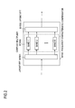
- Fig. 2 shows an example structure of the frequency characteristic compensator 901B3.
- the frequency characteristic compensator 901B3 includes a J-point FFT 901B31, a complex multiplier 901B32, and a J-point IFFT 901B33.
- the FFT 901B31 converts the input signal of the frequency characteristic compensator 901B3 into the frequency domain.
- the complex multiplier 901B32 multiplies each of M bands formed by dividing the upper band and lower band of the distortion component, as shown in Fig. 3 , by a frequency characteristic compensator coefficient given by the controller 907 (phase and amplitude adjustment).
- the output of the FFT 901B31 outside the divided bands is directly input to the IFFT 901B33, which is not shown in the figure.
- the IFFT 901B33 converts the output of the complex multiplier 901B32 into the time domain.
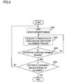
- Fig. 4 shows a flowchart illustrating processing for frequency characteristic compensator coefficients that minimize the distortion component, in the frequency characteristic compensator.
- the controller 907 specifies one band where the frequency characteristic compensator coefficient is to be adjusted (band specification step S900), adjusts the frequency characteristic compensator coefficient to reduce the power of the distortion component in the specified band to the minimum level (or a target value), and sets the coefficient in the frequency characteristic compensator (frequency characteristic compensator coefficient adjustment steps S901, S902).
- the controller 907 ends the frequency characteristic compensator coefficient adjustment process and sets the obtained frequency characteristic compensator coefficients in the frequency characteristic compensator (S903).
- the controller 907 goes back to the band specification step and repeats the steps S900, S901, and S902 until the conditions 1 and 2 are satisfied (S903).
- the frequency characteristic compensator 901B3 has eight bands, the time required to adjust the frequency characteristic compensator coefficients of all the bands once is twice the time required by a frequency characteristic compensator having four bands.
- a power series digital predistorter adds to an input signal a distortion compensation component for cancelling a distortion component generated in a power amplifier.
- the power series digital predistorter includes a linear transfer path adapted to transfer the input signal with a delay; a distortion generation path outputting the output of an N-th order frequency characteristic compensator as the distortion compensation component, where N is a predetermined odd number equal to or larger than three; a combiner adapted to combine the output of the linear transfer path and the output of the distortion generation path; a distortion observer adapted to observe the distortion component included in the output of the power amplifier, which is adapted to amplify the output of the combiner; and a controller adapted to set adjustment amounts for the amplitude and the phase in each of M bands in the N-th order frequency characteristic compensator according to an observation result of the distortion observer, where M is a predetermined integer equal to or larger than two.
- the distortion generation path includes an N-th order distortion generator adapted to generate an N-th order distortion component of the input signal; an N-th order distortion vector adjuster adapted to adjust the amplitude and the phase of the N-th order distortion component; and the N-th order frequency characteristic compensator, which is adapted to divide the output of the N-th order distortion vector adjuster into the M bands in the frequency domain and to adjust the amplitude and the phase of the output in each of the M bands.
- the controller includes a phase setting unit adapted to collectively set the adjustment amounts for the phases in the M bands in the N-th order frequency characteristic compensator; an amplitude setting unit adapted to collectively set the adjustment amounts for the amplitudes in the M bands in the N-th order frequency characteristic compensator; and a processing control unit.
- the processing control unit is adapted to determine whether an index indicating the degree of cancellation of the distortion component generated in the power amplifier satisfies a preset condition, and, if the index does not satisfy the condition, to perform control such that the phase setting unit again collectively sets the adjustment amounts for the phases and the amplitude setting unit again collectively sets the adjustment amounts for the amplitudes.
- a distortion compensation control method for a power series digital predistorter includes a phase setting step of collectively setting adjustment amounts for the phases in bands in an N-th order frequency characteristic compensator; an amplitude setting step of collectively setting adjustment amounts for the amplitudes in the bands in the N-th order frequency characteristic compensator; and a processing control step of determining whether an index indicating the degree of cancellation of a distortion component generated in a power amplifier satisfies a preset condition, and, if the index does not satisfy the condition, of performing control such that the phase setting step and the amplitude setting step are performed again.
- the frequency characteristic compensator coefficients can be adjusted at high speed.
- First Embodiment Fig. 5 shows the structure of a power series digital predistorter 100 of a first embodiment of the present invention and its peripheral equipment.
- the peripheral equipment shown in Fig. 5 includes a digital predistorter input signal generator 990, an amplifier 950, and a feedback signal generator 960 which takes in a part of the output of the amplifier 950 and generates a feedback signal for the power series digital predistorter 100.
- the amplifier 950 and the feedback signal generator 960 are the same as the peripheral equipment of the digital predistorter 900, which has been described as the related art, and therefore, a repeated description will be omitted (see the foregoing description).
- the digital predistorter input signal generator 990 includes a transmission signal generator 991, a pilot signal generator 992, and a switch 993 for selecting the output of the transmission signal generator 991 or the output of the pilot signal generator 992.
- the digital input transmission signal output from the transmission signal generator 991 includes desired information.
- the pilot signal output by the pilot signal generator 992 is used when frequency characteristic compensator coefficients, which will be described later, are determined.
- the frequency and the like of the pilot signal are not especially limited.
- the digital input transmission signal and the pilot signal include the I-phase signal and the Q-phase signal (I/Q signals) each.
- the power series digital predistorter 100 in the first embodiment includes a linear transfer path 101A, an N-th order distortion generation path 101B, dividers 102, combiners 103, digital-to-analog converters (DACs) 104, analog-to-digital converters (ADCs) 105, a distortion observer 106, and a controller 107.
- the linear transfer path 101A includes a delay unit 101A1.
- the N-th order distortion generation path 101B includes an N-th order distortion generator 101B1, an N-th order distortion vector adjuster 101B2, and an N-th order frequency characteristic compensator 101B3.
- the dividers 102 divide the I-phase signal and the Q-phase signal into the linear transfer path 101A and the N-th order distortion generation path 101B.
- the combiners 103 combine the outputs of the linear transfer path 101A and the outputs of the N-th order distortion generation path 101B for the I-phase signal and the Q-phase signal.
- the digital-to-analog converters (DACs) 104 convert the I-phase signal and the Q-phase signal output from the combiners 103 (digital I/Q signals with distortion compensation signals added thereto) separately to analog I/Q signals.
- the analog-to-digital converters (ADCs) 105 convert the outputs (analog I/Q signals) of the feedback signal generator 960 which takes in a part of the output of the amplifier 950 as the feedback signal, to digital I/Q signals.
- the distortion observer 106 observes the outputs (digital I/Q signals) of the ADCs 105 and measures the power in the transmission signal band and the power of the N-th order distortion component generated by the amplifier 950 in bands divided by the N-th order frequency characteristic compensator 101B3.
- the controller 107 adjusts the vector coefficients (amplitude and phase) to be set in the N-th order distortion vector adjuster 101B2 and one or more frequency characteristic compensator coefficients (amplitude and phase) to be set in the N-th order frequency characteristic compensator 101B3, in accordance with the output of the distortion observer 106.
- N is a predetermined odd number equal to or larger than 3. In this example, N is 3.
- the controller 107 includes a phase setting unit 1071, an amplitude setting unit 1072, and a processing control unit 1073 (see Fig. 6 ).
- the phase setting unit 1071 sets the phase adjustment amounts of M distortion component bands collectively in the third-order frequency characteristic compensator 101B3.
- the amplitude setting unit 1072 sets the amplitude adjustment amounts of M distortion component bands (M is a predetermined integer equal to or larger than 2) collectively in the third-order frequency characteristic compensator 101B3.
- the processing control unit 1073 judges whether an index (ACLR, for example, as described later) indicating the degree of cancellation of the distortion component generated by the power amplifier 953 satisfies a predetermined condition (lower than or lower than or equal to the target value). If the condition is not satisfied, the phase setting unit 1071 is controlled to set the phase adjustment amounts again, and the amplitude setting unit 1072 is controlled to set the amplitude adjustment amounts again.
- ACLR an index
- just the third-order distortion component is the target of compensation. If one or more different W-th order distortion generation paths (W is an odd number equal to or larger than 5) are connected in parallel to the third-order distortion generation path 101B, a plurality of odd-order distortion components can become the compensation target.
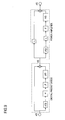
- the third-order frequency characteristic compensator 101B3 converts the outputs of the third-order distortion vector adjuster 101B2 into the frequency domain and divides the upper and lower third-order distortion component bands into M parts, as shown in Fig. 3 .
- the third-order frequency characteristic compensator 101B3 includes a serial-to-parallel converter (S/P) 101B31, a fast Fourier transformer (FFT) 101B32, a complex multiplier (C.M.) 101B33, an inverse fast Fourier transformer (IFFT) 101B34, and a parallel-to-serial converter (P/S) 101B35.
- the S/P 101B31 converts the outputs of the third-order distortion vector adjuster 101B2 from serial to parallel.
- the FFT 101B32 converts the outputs of the S/P 101B31 into the frequency domain.
- the complex multiplier 101B33 adjusts the phase and amplitude by multiplying them by the frequency characteristic compensator coefficients given by the controller 107 in each of the M divided bands.
- the IFFT 101B34 converts the outputs of the complex multiplier 101B33 into the time domain.
- the P/S 101B35 converts the outputs of the IFFT 101B34 from parallel to serial.
- the third-order frequency characteristic compensator 101B3 adjusts the phase and amplitude in each of the M divided bands by using the frequency characteristic compensation coefficients (phase and amplitude) specified by the controller 107.
- the input signals of the digital predistorter 100 are the outputs (pilot signals) of the pilot signal generator 992 until the third-order distortion components are minimized (to the target value or below). After the third-order distortion components are minimized (to the target value or below), the switch 993 selects the outputs (transmission signals) of the transmission signal generator 991 as the input signals.
- the OFDM signal comprises 64 subcarriers with signal bandwidth of 3.84 MHz, and a route roll off rate of 0.22.
- the modulation scheme for each subcarrier is QPSK.
- the bandwidth, route roll off rate, the number of subcarriers, subcarrier modulation scheme, and the like can be specified as needed.
- the transmission signal can be specified appropriately for the signal to be amplified by the amplifier 950 and can be the WCDMA signal, for example.
- the adjacent channel leakage power ratio (ACLR) is used as an index for judging the degree of distortion compensation (index indicating the degree of cancellation of the distortion component generated by the power amplifier).
- the ACLR here is the ratio of the power in the upper and lower bands of third-order distortion component (3.84 MHz-bandwidth) at ⁇ 5 MHz offset from the center frequency to the power in the transmission signal band (3.84 MHz-bandwidth).
- the offset from the center frequency and the third-order distortion component band can be specified appropriately for the bandwidth of the transmission signal.
- the distortion compensation judgment index used in the first embodiment is ACLR, and the upper or lower band of third-order distortion component can also be used as the index.
- the phase adjustment amount and amplitude adjustment amount of the third-order distortion vector adjuster 101B2 are considered to have been specified appropriately by a known method. If the power of the third-order distortion component band is used as an index, for example, the controller 107 sets a phase adjustment amount and amplitude adjustment amount in the third-order distortion vector adjuster 101B2 such that the power of the upper or lower band of third-order distortion component is minimized (reaches the target value).
- One method for determining the phase adjustment amount and amplitude adjustment amount is a perturbation method (see Toshio Nojima, Yoshiharu Okamoto, Satoshi Oyama, "Predistortion Nonlinear Compensator for Microwave SSB-AM System", IEICE Transactions, Vol. J67-B, No.
- the phase adjustment amount is determined by using the perturbation method
- the power of the third-order distortion component band is measured when the phase adjustment amount is set to those immediately larger and smaller than the phase adjustment amount set first; the phase adjustment amount is changed by an offset value in the direction in which the power of the third-order distortion component band decreases; and the power of the third-order distortion component band is measured.
- the phase adjustment amount that minimizes the power of the third-order distortion component band is obtained. The same process can be applied to the amplitude.
- the controller 107 has a functional element to set the phase adjustment amount and amplitude adjustment amount in the third-order distortion vector adjuster 101B2
- the process of setting the phase adjustment amount and amplitude adjustment amount in the third-order distortion vector adjuster 101B2 is carried out prior to and independently of the process of setting a phase adjustment amount and an amplitude adjustment amount in the third-order frequency characteristic compensator 101B3. Therefore, the functional element is not shown in the figure.
- the phase setting unit 1071 of the controller 107 sets the phase adjustment amounts of the M distortion component bands collectively in the third-order frequency characteristic compensator 101B3 (collective phase adjustment process in step S101).
- the amplitude setting unit 1072 of the controller 107 sets the amplitude adjustments of the M distortion component bands collectively in the third-order frequency characteristic compensator 101B3 (collective amplitude adjustment process in step S102).
- the distortion observer 106 measures the power in the transmission signal band and the power in the M distortion component bands and obtains an ACLR (ACLR measurement process in step S103).
- the processing control unit 1073 of the controller 107 repeats steps S101 to S103 until the measured ACLR falls below the target value (ACLR judgment process in step S104).
- the phase adjustment amounts of the M distortion component bands are specified collectively.
- the amplitude adjustment amounts of the M distortion component bands are specified collectively. This is because the increase or decrease in the distortion component corresponding to the change in phase is generally larger than the increase or decrease in the distortion component corresponding to the change in amplitude.
- phase adjustment process 1 The collective phase adjustment process of the controller 107 will be described (this process will be referred to as collective phase adjustment process 1).
- phase adjustment amount to be specified in each of the M divided bands of the third-order frequency characteristic compensator 101B3 will be denoted by X m (0 ⁇ m ⁇ M), and the distortion component power in the divided band will be denoted by D m .
- Fig. 9 shows an equivalent low-pass system model of the digital predistorter and power amplifier.
- the power amplifier is formed of an amplification path and a third-order distortion generation path.
- s(t) denotes the input signal of the digital predistorter; ⁇ and ⁇ respectively denote the amplitude and phase of the third-order distortion vector adjuster in the digital predistorter; g(t) denotes the impulse response of the third-order frequency characteristic compensator in the digital predistorter; r 1 denotes the gain of the amplification path in the power amplifier; r 3 and ⁇ respectively denote the gain and phase of the third-order distortion generation path in the power amplifier; and h(t) denotes the impulse response indicating the frequency dependence of the third-order distortion component in the power amplifier.
- the output signal z(t) of the power amplifier can be expressed as follows.
- z t r 1 ⁇ s t + ⁇ ⁇ e j ⁇ ⁇ g t * s 3 t + r 3 ⁇ e j ⁇ ⁇ h t * s t + ⁇ ⁇ e j ⁇ ⁇ g t * s 3 t 3
- the asterisk (*) indicates convolution.
- the distortion component e(t) can be expressed as follows.
- e t r 3 ⁇ e j ⁇ ⁇ h t * s 3 t + r 1 ⁇ ⁇ ⁇ e j ⁇ ⁇ g t * s 3 t Equation (2) converted into the frequency domain is as follows.
- E f r 3 ⁇ e j ⁇ ⁇ H f + r 1 ⁇ ⁇ e j ⁇ ⁇ G f ⁇ S 3 f
- E(f), H(f), G(f), and S 3 (f) are L-point discrete Fourier transforms of e(t), h(t), g 3 (t), and s 3 (t), respectively.
- the frequency characteristic H m of the distortion component in the divided band m of the third-order frequency characteristic compensator is expressed as follows.
- H m K m ⁇ e j ⁇ ⁇ m
- G m is expressed as given below.
- Equation (3) the power D m of the distortion component in the divided band m is expressed as follows.
- Equation (7) the relationship between Y m and D m when X m is a constant X m (0) can be expressed as given below: D m
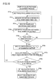
- Fig. 10 shows a flowchart illustrating the collective phase adjustment process 1.
- the phase setting unit 1071 of the controller 107 sets initial phase adjustment amounts X 1 to X M collectively in the third-order frequency characteristic compensator 101B3 (phase step S11p).
- the distortion observer 106 measures the powers D 1 to D M of the distortion component bands simultaneously (phase step S12p).
- the output signal of the amplifier 950 is converted to analog I/Q signals by the feedback signal generator 960, and the analog I/Q signals are converted to digital I/Q signals by the ADCs 105.
- the distortion observer 106 converts the digital I/Q signals from serial to parallel, then multiplies them by a window function (such as the Hamming window), and performs the discrete Fourier transform. Because the spectrum of the distortion component can be obtained collectively from the result of the discrete Fourier transform, the distortion observer 106 measures the powers D 1 to D M of the distortion component collectively from the results of the discrete Fourier transform.
- the conventional distortion observer 906 observes the power of a specified band only.
- the distortion observer 106 in the first embodiment measures the powers D 1 to D M of the M distortion component bands collectively.
- the phase setting unit 1071 of the controller 107 records the set phase adjustment amount X m and the measured power D m as R1 m,11 and R2 m,11 (0 ⁇ 11 ⁇ L1) in each band (phase step S13p).
- the phase setting unit 1071 of the controller 107 adds predetermined offset values A1 1 to A1 M (positive values) to the phase adjustment amounts X 1 to X M and sets the new phase adjustment amounts X 1 to X M collectively in the third-order frequency characteristic compensator 101B3 (phase step S14p).
- the phase setting unit 1071 of the controller 107 repeats the phase steps S12p to S14p L1 times (L1 is an integer equal to or larger than 3) (phase step S15p).
- negative offset values may be added to the phase adjustment amounts.
- a positive offset value may be added to the phase adjustment amount in odd-numbered distortion compensation bands, and a negative offset value may be added to the phase adjustment amount in even-numbered distortion compensation bands.
- the process may be modified such that, if the judgment made in the phase step S15p is No, the phase step S14p is executed.
- phase setting unit 1071 of the controller 107 calculates the phase adjustment amount X min,m that minimizes the quadratic function, as -a 1,m /(2a 2,m ) (phase step S17p).
- the phase setting unit 1071 of the controller 107 repeats the phase steps S16p and S 17p until the phase adjustment amount X min,m is calculated in all the distortion component bands (phase step S18p).
- the phase setting unit 1071 of the controller 107 sets the phase adjustment amounts X min,1 to X min,M collectively in the third-order frequency characteristic compensator 101B3 (phase step S19p).
- the relationship between the phase adjustment amount and the distortion component can be represented by a quadratic function by using the Taylor expansion on Equation (7), as descried earlier.
- X m is calculated so that D m is minimized with the specified coefficients (c 2,m , c 1,m , c 0,m ). For example, if X m is in radians, X min,m is calculated as ⁇ - c 1,m . Since the cosine function is used instead of approximation by the Taylor expansion, the relationship between the phase adjustment amount and the distortion component may be represented more accurately than when the quadratic function is used. The distortion compensation amount obtained by using the cosine function becomes larger than that obtained by using the quadratic function, and it may be possible to reach the target value with a smaller number of repetitions. Instead of the cosine function, a sine function can be used by utilizing the supplementary angle formula. In other embodiments described later, the relationship between the phase adjustment amount and the distortion component may be a cosine function.
- the collective amplitude adjustment process in the controller 107 is as illustrated by a flowchart shown in Fig. 11 (this process will be referred to as collective amplitude adjustment process 1).
- this process will be referred to as collective amplitude adjustment process 1).
- the amplitude adjustment amount to be specified in each of the M divided bands of the third-order frequency characteristic compensator 101B3 will be denoted by Y m .
- the amplitude setting unit 1072 of the controller 107 sets initial amplitude adjustment amounts Y 1 to Y M collectively in the third-order frequency characteristic compensator 101B3 (amplitude step S11a).
- the distortion observer 106 measures the distortion component powers D 1 to D M simultaneously (amplitude step S12a).
- the amplitude setting unit 1072 of the controller 107 records the set amplitude adjustment amount Y m and the measured power D m as R3 m,12 and R4 m,12 (0 ⁇ 12 ⁇ L2) in each band (amplitude step S13a).
- the amplitude setting unit 1072 of the controller 107 adds predetermined offset values B1 1 to B1 M (positive values) to the amplitude adjustment amounts Y 1 to Y M and sets the new amplitude adjustment amounts Y 1 to Y M collectively in the third-order frequency characteristic compensator 101B3 (amplitude step S14a).
- the amplitude setting unit 1072 of the controller 107 repeats the amplitude steps S12a to S14a L2 times (L2 is an integer equal to or larger than 3) (amplitude step S15a). In the amplitude step S14a, if the amplitude is larger than 0, a negative offset value may be added to the amplitude adjustment amount.
- a positive offset value may be added to the amplitude adjustment amount in odd-numbered distortion compensation bands
- a negative offset value may be added to the amplitude adjustment amount in even-numbered distortion compensation bands.
- the process may be modified such that, if the judgment made in the amplitude step S15a is No, the amplitude step S 14a is executed.
- the amplitude setting unit 1072 of the controller 107 calculates the amplitude adjustment amount Y min,m that minimizes the quadratic function, as -b 1,m /(2b 2,m ) (amplitude step S17a).
- the amplitude setting unit 1072 of the controller 107 repeats the amplitude steps S16a and S17a until the amplitude adjustment amount Y min,m is calculated in all the distortion component bands (amplitude step S18a).
- the amplitude setting unit 1072 of the controller 107 sets the amplitude adjustment amounts Y min,i to Y min,M collectively in the third-order frequency characteristic compensator 101B3 (amplitude step S19a).
- (1) indicates the processing time for setting the phase adjustment amount and measuring the distortion component; (2) indicates the time needed to calculate the phase adjustment amount that minimizes the quadratic function; and (3) indicates the processing time for setting the calculated phase adjustment amount.
- the periods (1), (2), and (3) are equally sized in Fig. 13 for the sake of simplicity, but they actually differ in size.
- the processes corresponding to (1) to (3) are executed for one band after another in method A, whereas the processes are executed for all the distortion component bands collectively in method B.
- the phase adjustment amounts can be determined more quickly by method B than by method A.
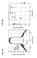
- Fig. 14A shows a spectrum (marked by "without frequency characteristic compensator") before phase adjustment amounts and amplitude adjustment amounts are set in the third-order frequency characteristic compensator 101B3, a spectrum when method A is used, and a spectrum when method B is used.
- Fig. 14B shows the upper and lower ACLRs for the normalized time.
- the setting times in methods A and B were normalized separately on the horizontal axis with reference to the period required to specify the phase adjustment amounts and amplitude adjustment amounts that reduce the distortion component to the minimum level (target level) in all the bands by method A.
- Fig. 14A shows that the distortion compensation amount in the lower spectrum by method B is smaller than that by method A.
- Fig. 14B shows that both the upper ACLR and the lower ACLR are below the target value in methods A and B.
- the normalized time of method B is 0.28, and the normalized time of method A is 1.0. This means that method B reduces the setting time by 72% compared with the conventional control method A.
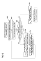
- the collective phase adjustment process by the controller 107 may be as illustrated in a flowchart shown in Fig. 15 (this process will be referred to as collective phase adjustment process 2).
- the controller 107 sets initial phase adjustment amounts X 1 to X M collectively in the third-order frequency characteristic compensator 101B3 (phase step S21p).
- the distortion observer 106 measures the distortion component powers D 1 to D M simultaneously (phase step S22p).
- the controller 107 compares the distortion component power D m with a recorded value R5 m in each band (phase step S23p). If the distortion component power becomes smaller than the recorded value in one band at least, the controller 107 records the phase adjustment amount X m and the distortion component power D m in the band where the distortion component power D m is lower than the recorded value R5 m as X mm , m and as the recorded value R5 m , respectively (phase step S24p).
- the initial value of the recorded value R5 m is set to a value higher than the highest distortion component power D m that can be measured. This causes the phase step S24p to be executed at least once in all the bands and the phase adjustment amount X min , m to be recorded in all the bands.
- the controller 107 adds the offset value A2 m (A2 m > 0) to the phase adjustment amount X m , sets the new phase adjustment amount in the band where the distortion component power D m is lower than the recorded value R5 m (phase step S25p), and returns to the phase step S22p. In that step, a negative offset value may be added to the phase adjustment amount. If the distortion component power is equal to or higher than the recorded value in all the bands, the controller 107 sets the recorded phase adjustment amounts X mm,1 to X mim,M collectively in the third-order frequency characteristic compensator 101B3 (phase step S26p).
- the collective amplitude adjustment process by the controller 107 may be as illustrated in a flowchart shown in Fig. 16 (this process will be referred to as collective amplitude adjustment process 2).
- the controller 107 sets initial amplitude adjustment amounts Y 1 to Y M collectively in the third-order frequency characteristic compensator 101B3 (amplitude step S21a).
- the distortion observer 106 measures the distortion component powers D 1 to D M simultaneously (amplitude step S22a).
- the controller 107 compares the distortion component power D m with a recorded value R6 m in each band (amplitude step S23a). If the distortion component power is smaller than the recorded value in one band at least, the controller 107 records the amplitude adjustment amount Y m and the distortion component power D m in the band where the distortion component power D m is lower than the recorded value R6 m as Y min,m and recorded value R6 m , respectively (amplitude step S24a).
- the initial value of the recorded value R6 m is set to a value higher than the highest distortion component power D m that can be measured. This causes the amplitude step S24a to be executed at least once in all the bands and the amplitude adjustment amount Y min,m to be recorded in all the bands.
- the controller 107 adds the offset value B2 m (B2 m > 0) to the amplitude adjustment amount Y m , sets the new amplitude adjustment amount in the band where the distortion component power D m is lower than the recorded value R6 m (amplitude step S25a), and returns to the amplitude step S22a. In that step, if the amplitude adjustment amount Y m is larger than 0, a negative offset value may be added to the amplitude adjustment amount.
- the controller 107 sets the recorded amplitude adjustment amounts Y min,1 to Y min,M collectively in the third-order frequency characteristic compensator 101B3 (amplitude step S26a).
- the collective amplitude adjustment process may be repeated, and then the ACLR measurement may be performed.
- the first phase adjustment amount is specified such that the phase adjustment amount that minimizes the quadratic function becomes the median among the L1 phase adjustment amounts.
- the offset value may be changed to 2/3 times, 1/2 times, or the like, or may not be changed.
- the amplitude adjustment amounts are specified in the same manner as the phase adjustment amounts. If the collective phase adjustment process 2 and the collective amplitude adjustment process 2 are used, the phase adjustment amount offset values and the amplitude adjustment amount offset values are changed to 2/3 times, 1/2 times, or the like, respectively.
- the collective phase adjustment process 1 when the collective phase adjustment process 1 is used, the collective amplitude adjustment process 1 is used together therewith, but the collective amplitude adjustment process 2 may be used.
- the collective amplitude adjustment process 2 when the collective phase adjustment process 2 is used, the collective amplitude adjustment process 2 is used together therewith, but the collective amplitude adjustment process 1 may be used.
- the distortion component may increase.
- a lookup table may be provided so that the phase adjustment amounts and amplitude adjustment amounts of the third-order frequency characteristic compensator 101B3 can be specified appropriately for the transmission signal power.
- the lookup table stores the phase adjustment amounts and amplitude adjustment amounts to be set in the third-order frequency characteristic compensator 101B3 on the basis of the transmission signal power.
- the phase adjustment amounts and amplitude adjustment amounts to be stored are obtained in accordance with the transmission signal power, through the processes described earlier.
- the distortion observer 106 measures the transmission signal power, and the controller 107 references the lookup table to set phase adjustment amounts and amplitude adjustment amounts suitable for the transmission signal power in the third-order frequency characteristic compensator 101B3.
- the processes in the first embodiment do not depend on the order of the distortion in the distortion generation path 101B. If there are a plurality of distortion generation paths 101B, the processes described earlier should be performed in one distortion generation path 101B after another. If there are a third-order distortion generation path and a fifth-order distortion generation path and if a third-order distortion vector adjuster and a fifth-order distortion vector adjuster are controlled appropriately, for example, the phase adjustment amounts and amplitude adjustment amounts of all the bands to be set in the third-order frequency characteristic compensator should be adjusted in the processes described earlier, and the phase adjustment amounts and amplitude adjustment amounts of all the bands to be set in the fifth-order frequency characteristic compensator should be adjusted in the same way.
- the adjustment for the fifth-order frequency characteristic compensator may be followed by the adjustment for the third-order frequency characteristic compensator.
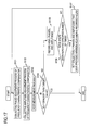
- Second Embodiment Fig. 17 shows a flowchart illustrating processing in a second embodiment of the present invention.
- the following processes are added at the transition from the ACLR judgment process to the collective phase adjustment process, in the first embodiment: a process for recording the measured ACLR and the phase adjustment amounts and amplitude adjustment amounts set in the third-order frequency characteristic compensator 101B3 (ACLR, phase, and amplitude recording process in step S105) and a process for determining whether processes (collective phase adjustment process, collective amplitude adjustment process, and ACLR measurement process) have been repeated a specified number of times (first repetition judgment process in step S106).
- ACLR third-order frequency characteristic compensator 101B3
- first repetition judgment process in step S106
- the controller 107 proceeds to the collective phase adjustment process described in the first embodiment. If the processes (collective phase adjustment process, collective amplitude adjustment process, and ACLR measurement process) have been repeated the specified number of times, the controller 107 collectively sets the phase adjustment amounts and amplitude adjustment amounts that have provided the minimum ACLRs of the ACLRs recorded in the ACLR, phase, and amplitude recording process, in all the bands of the third-order frequency characteristic compensator 101B3 (S107).
- the phase adjustment amounts and amplitude adjustment amounts that provide the smallest ACLRs among the ACLRs obtained in the processes repeated the specified number of times can be set in the third-order frequency characteristic compensator 101B3 without generating an endless loop.
- ACLRs are recorded. If the index of the distortion compensation amount in the third-order frequency characteristic compensator 101B3 is the power of the distortion component, the distortion component power is recorded instead of the ACLR in the ACLR, phase, and amplitude recording process (S105). In that case, the controller 107 collectively sets the phase adjustment amounts and amplitude adjustment amounts corresponding to the smallest distortion component powers among the recorded distortion component powers, in all the bands of the third-order frequency characteristic compensator 101B3.
- the frequency characteristic compensator coefficients (phase and amplitude) can be adjusted quickly, as clearly indicated by the first embodiment.
- Fig. 18 shows a flowchart of processing in the third embodiment of the present invention.
- the third embodiment differs from the second embodiment in that, when it is judged in the first repetition judgment process S106 that the processes have been repeated the specified number of times, it is judged whether the collective phase adjustment process and the collective amplitude adjustment process have been modified once (modification judgment process in step S106a). If no modification has been made, the collective phase adjustment process and the collective amplitude adjustment process are modified together (process for modifying the collective phase adjustment process and the collective amplitude adjustment process in step S106b).
- processing in the second embodiment is performed in a first stage in accordance with the collective phase adjustment process 1 and the collective amplitude adjustment process 1 described in the first embodiment
- processing in the next stage of the second embodiment is performed in accordance with the collective phase adjustment process 2 and the collective amplitude adjustment process 2 described in the first embodiment.
- Using two different pairs of the collective phase adjustment process and the collective amplitude adjustment process can provide better distortion compensation than using a single pair of the collective phase adjustment process and the collective amplitude adjustment process.
- the collective phase adjustment process and the collective amplitude adjustment process need not be changed together; just one process may be changed.
- processing in the second embodiment is performed in accordance with the collective phase adjustment process 1 and collective amplitude adjustment process 1 described in the first embodiment
- processing in the second embodiment is performed in accordance with the collective phase adjustment process 1 and collective amplitude adjustment process 2 described in the first embodiment
- processing in the third stage is performed in accordance with the collective phase adjustment process 2 and collective amplitude adjustment process 1 described in the first embodiment
- processing in the second embodiment is performed in accordance with the collective phase adjustment process 2 and collective amplitude adjustment process 1 described in the first embodiment
- processing in the second embodiment is performed in accordance with the collective phase adjustment process 2 and collective amplitude adjustment process 2 described in the first embodiment.
- Fourth Embodiment A fourth embodiment differs from the second embodiment in that the phase adjustment amounts and amplitude adjustment amounts are set individually if ACLR does not fall below the target value even after the processes (collective phase adjustment process, collective amplitude adjustment process, and ACLR measurement process) are repeated the specified number of times.
- Fig. 19 shows a flowchart illustrating processing in the fourth embodiment. The difference from the second embodiment is that, if it is judged in the first repetition judgment process in step S106 shown in Fig.
- the phase adjustment amount is adjusted in one band after another (individual phase adjustment process in step S108); the amplitude adjustment amount is adjusted in one band after another (individual amplitude adjustment process in step S109); the ACLR measurement process in step (S110) is carried out; and except when the ACLR falls below the target value (S111), the individual phase adjustment process to the ACLR measurement process (S 108 to S110) are repeated in that order up to a specified number of times (second repetition judgment process in step S113).
- an ACLR, phase, and amplitude recording step S112 which is the same as the ACLR, phase, and amplitude recording step S105 described in the second embodiment, is performed. If the ACLR does not fall below the target value after the individual phase adjustment process S108 to the ACLR measurement process S110 are repeated, the controller 107 collectively sets the phase adjustment amounts and amplitude adjustment amounts corresponding to the minimum ACLRs among the measured ACLRs in the third-order frequency characteristic compensator 101B3.
- the repetition count judged in the second repetition judgment process in step S113 may or may not be the same as the repetition count judged in the first repetition judgment process in step S106.
- the amplitude adjustment amounts are adjusted. This is because the increase or decrease in the distortion component corresponding to the change in phase is generally larger than the increase or decrease in the distortion component corresponding to the change in amplitude. In some power amplifiers 953, however, the increase or decrease in the distortion component corresponding to the change in amplitude is larger than the increase or decrease in the distortion component corresponding to the change in phase. In that case, the phase adjustment and amplitude adjustment may be performed in reverse order.
- the controller 107 sets the phase adjustment amount X m in the band m (phase step S31p).
- the distortion observer 106 measures the distortion component power D m in the band m (phase step S32p).
- the controller 107 records the set phase adjustment amount X m and the measured power D m as R7 m,13 and R8 m , 13 (0 ⁇ 13 ⁇ L3), respectively (phase step S33p).
- the controller 107 adds an offset value A3 m (A3 m > 0) to the phase adjustment amount X m and sets the new phase adjustment amount X m in the band m (phase step S34p).
- the controller 107 repeats the phase steps S32p to S34p L3 times (L3 is an integer equal to or larger than 3) (phase step S35p).
- phase step S34p a negative offset value may be added to the phase adjustment amount.
- the controller 107 calculates the phase adjustment amount X min,m that minimizes the quadratic function, as -a 1,m /(2a 2,m ) (phase step S37p).
- the controller 107 sets the obtained phase adjustment amount X min,m in the third-order frequency characteristic compensator 101B3 (phase step S38p).
- the controller 107 repeats the phase steps S31p to S38p until the phase adjustment amount X min,m is set in all the distortion component bands (phase step S39p).
- the process may be changed such that, if judgment made in the phase step S35p is No, the phase step S34p is executed.
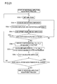
- the individual amplitude adjustment process is performed as illustrated in a flowchart shown in Fig. 21 (this process will be referred to as individual amplitude adjustment process 1).
- the controller 107 sets the amplitude adjustment amount Y m in the band m (amplitude step S31a).
- the distortion observer 106 measures the distortion component power D m in the band m (amplitude step S32a).
- the controller 107 records the set amplitude adjustment amount Y m and the measured power D m as R9 m,14 and R10 m,14 (0 ⁇ 14 ⁇ L4) (amplitude step S33a).
- the controller 107 adds an offset value B3 m (B3 m > 0) to the amplitude adjustment amount Y m and sets the new amplitude adjustment amount Y m in the band m (amplitude step S34a).
- the amplitude steps S31a to S34a are repeated L4 times (L4 is an integer equal to or larger than 3) (amplitude step S35a).
- L4 is an integer equal to or larger than 3
- amplitude step S35a When the amplitude adjustment amount is larger than 0, a negative offset value may be added to the amplitude adjustment amount in the amplitude step S34a.
- the controller 107 calculates the amplitude adjustment amount Y min,m that minimizes the quadratic function, as -b 1,m /(2b 2,m ) (amplitude step S37a).
- the controller 107 sets the obtained amplitude adjustment amount Y min,m in the third-order frequency characteristic compensator 101B3 (amplitude step S38a).
- the controller 107 repeats the amplitude steps S31a to S38a until the amplitude adjustment amount Y min,m is set in all the distortion component bands (amplitude step S39a).
- the individual phase adjustment process may be as illustrated in a flowchart shown in Fig. 22 (this process will be referred to as individual phase adjustment process 2).
- the controller 107 sets the phase adjustment amount X m in the band m (phase step S41p).
- the distortion observer 106 measures the distortion component power D m in the band m (phase step S42p).
- the controller 107 compares the distortion component power D m with a recorded value R11 m (phase step S43p). If the distortion component power D m falls below the recorded value R11 m , the controller 107 records the phase adjustment amount X m as X min,m and the distortion component power D m as the recorded value R11 m (phase step S44p).
- the initial value of the recorded value R11 m is set to a value higher than the highest distortion component power D m that can be measured.
- phase step S44p This causes the phase step S44p to be performed once at least and the phase adjustment amount X min,m to be recorded.
- the controller 107 adds the offset value A4 m (A4 m > 0) to the phase adjustment amount X m , sets the new phase adjustment amount X m in the band m (phase step S45p), and returns to the phase step S42p. In that step, a negative offset value may be added to the phase adjustment amount. If the distortion component power D m becomes equal to or higher than the recorded value R11 m , the controller 107 sets the recorded phase adjustment amount X min,m in the band m (phase step S46p). The controller 107 repeats the processes until the phase adjustment amount X min,m is set in all the distortion component bands (phase step S47p).
- the individual amplitude adjustment process may be as illustrated in a flowchart shown in Fig. 23 (this process will be referred to as individual amplitude adjustment process 2).
- the controller 107 sets the amplitude adjustment amount Y m of the band m (amplitude step S41a).
- the distortion observer 106 measures the distortion component power D m in the band m (amplitude step S42a).
- the controller 107 compares the distortion component power D m with a recorded value R12 m (amplitude step S43a). If the distortion component power D m is smaller than the recorded value R12 m , the controller 107 records the amplitude adjustment amount Y m as Y min,m and the distortion component power D m as the recorded value R12 m (amplitude step S44a).
- the initial value of the recorded value R12 m is set to a value higher than the highest distortion component power D m that can be measured.
- the controller 107 adds the offset value B4 m to the amplitude adjustment amount Y m , sets the new amplitude adjustment amount Y m in the band m (amplitude step S45a), and returns to the amplitude step S42a. If the amplitude adjustment amount is larger than 0, a negative offset value may be added to the amplitude adjustment amount.
- the controller 107 sets the recorded amplitude adjustment amount Y min,m in the band m (amplitude step S46a). The controller 107 repeats the processes described above until the amplitude adjustment amount Y min,m is set in all the distortion component bands (amplitude step S47a).
- the fourth embodiment may be modified such that, in the collective adjustments made in all the bands as in the third embodiment, the collective phase adjustment process and/or the collective amplitude adjustment process is changed after the first repetition judgment process; and/or, in the adjustment made in one band after another, the individual phase adjustment process and/or the individual amplitude adjustment process is changed after the second repetition judgment process.
- Modification A modification of the fourth embodiment will be described with reference to Fig. 24 .
- This modification differs from the fourth embodiment in that the third-order frequency characteristic compensator 101B3 sets a phase adjustment amount and an amplitude adjustment amount in one band and then sets a phase adjustment amount and an amplitude adjustment amount in another band (S106c, S106d).
- ACLR can be brought to a value smaller than the target value with a smaller number of repetitions than when the amplitude adjustment amounts are adjusted in all the bands after the phase adjustment amounts are adjusted in all the bands, as in the fourth embodiment.
- the phase adjustment and the amplitude adjustment may be made in that order or in reverse order.
- phase and amplitude adjustment process will be described with reference to Fig. 25 (this process will be referred to as individual phase and amplitude adjustment process 1).
- the phase adjustment amount to be specified in each of M divided bands of the third-order frequency characteristic compensator 101B3 is denoted by X m,15 (0 ⁇ m ⁇ M, 0 ⁇ 15 ⁇ L5); the amplitude adjustment amount is denoted by Y m,16 (0 ⁇ 16 ⁇ L6); and the distortion component power in the divided band is denoted by D m .
- the controller 107 sets the phase adjustment amount X m,15 in the band m (phase and amplitude step S51).
- the distortion observer 106 measures the distortion component power D m in the band m (phase and amplitude step S52).
- the controller 107 records the set phase adjustment amount X m,15 and the measured power D m as R13 m,15 and R14 m,15 , respectively (phase and amplitude step S53).
- the controller 107 repeats the phase and amplitude steps S51 to S53 until the distortion component power D m is measured for L5 different phase adjustment amounts X m,15 (L5 is an integer larger than 2) (phase and amplitude step S54).
- the controller 107 calculates the phase adjustment amount X min,m that minimizes the quadratic function, as -a 1,m /(2a 2,m ) (phase and amplitude step S56).
- the controller 107 sets the obtained phase adjustment amount X min,m in the band m (phase and amplitude step S57).
- the controller 107 sets the amplitude adjustment amount Y m,16 in the band m (phase and amplitude step S58).
- the distortion observer 106 measures the distortion component power D m in the band m (phase and amplitude step S59).
- the controller 107 records the set amplitude adjustment amount Y m,16 and the measured power D m as R15 m , 16 and R16 m,16, respectively (phase and amplitude step S60).
- the controller 107 repeats the phase and amplitude steps S58 to S60 until the distortion component power D m is measured for L6 different amplitude adjustment amounts Y m,16 (L6 is an integer larger than 2) (phase and amplitude step S61).
- the controller 107 calculates the amplitude adjustment amount Y min,m that minimizes the quadratic function, as -b 1,m /(2b 2,m ) (phase and amplitude step S63).
- the controller 107 sets the obtained amplitude adjustment amount Y min,m in the band m (phase and amplitude step S64).
- the individual phase and amplitude adjustment process may be as illustrated in a flowchart shown in Fig. 26 (this process will be referred to as individual phase and amplitude adjustment process 2).
- X m (0 ⁇ m ⁇ M) and Y m (0 ⁇ m ⁇ M) respectively denote the phase adjustment amount and the amplitude adjustment amount to be specified in each of the M divided bands of the third-order frequency characteristic compensator 101B3.
- the controller 107 sets the phase adjustment amount X m in the band m (phase and amplitude step S71).
- the distortion observer 106 measures the distortion component power D m in the band m (phase and amplitude step S72).
- the controller 107 compares the distortion component power D m with a recorded value R17 m (phase and amplitude step S73). If the distortion component power D m falls below the recorded value R17 m , the controller 107 records the phase adjustment amount X m as X min,m and the distortion component power D m as R17 m (phase and amplitude step S74).
- the initial value of R17 m is set to a value higher than the highest distortion component power D m that can be measured.
- phase and amplitude step S74 causes the phase and amplitude step S74 to be executed at least once and the phase adjustment amount X min,m to be recorded.
- the controller 107 adds an offset value A5 m to the phase adjustment amount X m , sets the new phase adjustment amount X m in the band m (phase and amplitude step S75), and returns to the phase amplitude step S72. If the distortion component power D m becomes equal to or higher than R17 m , the controller 107 sets the recorded phase adjustment amount X min,m in the band m (phase and amplitude step S76). The controller 107 sets the amplitude adjustment amount Y m in the band m (phase and amplitude step S77).
- the distortion observer 106 measures the distortion component power D m in the band m (phase and amplitude step S78).
- the controller 107 compares the distortion component power D m with a recorded value R18 m (phase and amplitude step S79). If the distortion component power D m becomes smaller than the recorded value R18 m , the controller 107 records the amplitude adjustment amount Y m as Y min,m and the distortion component power D m as R18 m (phase and amplitude step S80).
- the initial value of R18 m is set to a value higher than the highest distortion component power D m that can be measured. This causes the phase and amplitude step S80 to be performed at least once and the amplitude adjustment amount Y min,m to be recorded.
- the controller 107 adds an offset value B5 m to the amplitude adjustment amount Y m , sets the new amplitude adjustment amount Y m in the band m (phase and amplitude step S81), and returns to the phase and amplitude step S78. If the distortion component power D m becomes equal to or higher than R18 m , the controller 107 sets the recorded amplitude adjustment amount Y min,m in the band m (phase and amplitude step S82).
Landscapes
- Physics & Mathematics (AREA)
- Nonlinear Science (AREA)
- Engineering & Computer Science (AREA)
- Power Engineering (AREA)
- Amplifiers (AREA)
Abstract
Description
- The present invention relates to a power series digital predistorter and a distortion compensation control method therefor.
- Nonlinear distortion compensation methods for microwave power amplifiers (power amplifiers hereafter) include a predistortion method.
The predistortion method uses a predistorter to add, to a power amplifier input signal beforehand, a distortion compensation component for cancelling out a distortion component generated by the power amplifier. - The power amplifier generally provides high efficiency when it is operated at around the saturation output power. As the power amplifier approaches its saturation output power, the intermodulation distortion (distortion component hereafter) increases because of the nonlinear characteristics. In addition, the distortion component has frequency dependent. Predistorters that can compensate for the frequency dependent distortion component include a power series digital predistorter (digital predistorter hereafter) that compensates for the frequency dependence of the distortion component (refer to S. Mizuta, Y. Suzuki, S. Narahashi, and Y. Yamao, "A New Adjustment Method for the Frequency-Dependent IMD Compensator of the Digital Predistortion Linearizer," IEEE Radio and Wireless Symposium 2006, pp. 255-258, Jan. 2006.).
-
Fig. 1 shows a conventional structure of adigital predistorter 900 and its peripheral equipment. In the example shown, a digital input transmission signal includes an I-phase signal and a Q-phase signal (I/Q signals hereafter). Thedigital predistorter 900 includes alinear transfer path 901A, adistortion generation path 901B,dividers 902,combiners 903, digital-to-analog converters (DACs) 904, analog-to-digital converters (ADCs) 905, andistortion observer 906, and acontroller 907. Thelinear transfer path 901A includes a delay unit 901A1. Thedistortion generation path 901B includes a distortion generator 901B1, a distortion vector adjuster 901B2, and a frequency characteristic compensator 901B3. Thedividers 902 divide the input transmission signal into thelinear transfer path 901 A and thedistortion generation path 901B. Thecombiners 903 combine the outputs of thelinear transfer path 901A and the outputs of thedistortion generation path 901B. The digital-to-analog converters (DACs) 904 convert the outputs of the combiners 903 (digital I/Q signals with distortion compensation components added thereto) to analog I/Q signals. The analog-to-digital converters (ADCs) 905 convert the outputs (analog I/Q signals) of afeedback signal generator 960 that takes in a part of the output of anamplifier 950 as a feedback signal to digital I/Q signals. Thedistortion observer 906 detects a distortion component from the outputs of theADCs 905. Thecontroller 907 adjusts vector coefficients (amplitude and phase) to be set in the distortion vector adjuster 901B2 and one or more frequency characteristic compensator coefficients (amplitude and phase) to be set in the frequency characteristic compensator 901B3, in accordance with the output of thedistortion observer 906. - The
amplifier 950 includes aquadrature modulator 951 for performing quadrature modulation of the analog I/Q signals output from thedigital predistorter 900, afrequency upconverter 952 for converting the frequency of the modulated output to the carrier frequency, and apower amplifier 953 for performing power amplification of the frequency-converted signal, and supplies the power-amplified signal from anoutput terminal 970 to an antenna, for example, via a duplexer, not shown. - The
feedback signal generator 960 includes acoupler 961 that extracts a part of the output of theamplifier 950 as a feedback signal, afrequency downconverter 962 for converting the frequency of the feedback signal, and aquadrature demodulator 963 for performing quadrature demodulation of the down-converted feedback signal. -
Fig. 2 shows an example structure of the frequency characteristic compensator 901B3. The frequency characteristic compensator 901B3 includes a J-point FFT 901B31, a complex multiplier 901B32, and a J-point IFFT 901B33. The FFT 901B31 converts the input signal of the frequency characteristic compensator 901B3 into the frequency domain. The complex multiplier 901B32 multiplies each of M bands formed by dividing the upper band and lower band of the distortion component, as shown inFig. 3 , by a frequency characteristic compensator coefficient given by the controller 907 (phase and amplitude adjustment). The output of the FFT 901B31 outside the divided bands is directly input to the IFFT 901B33, which is not shown in the figure. The IFFT 901B33 converts the output of the complex multiplier 901B32 into the time domain. -
Fig. 4 shows a flowchart illustrating processing for frequency characteristic compensator coefficients that minimize the distortion component, in the frequency characteristic compensator. Thecontroller 907 specifies one band where the frequency characteristic compensator coefficient is to be adjusted (band specification step S900), adjusts the frequency characteristic compensator coefficient to reduce the power of the distortion component in the specified band to the minimum level (or a target value), and sets the coefficient in the frequency characteristic compensator (frequency characteristic compensator coefficient adjustment steps S901, S902). When the distortion component power in the specified band is minimized (condition 1) and when the distortion component power in each of all bands is minimized (condition 2), thecontroller 907 ends the frequency characteristic compensator coefficient adjustment process and sets the obtained frequency characteristic compensator coefficients in the frequency characteristic compensator (S903). If theconditions controller 907 goes back to the band specification step and repeats the steps S900, S901, and S902 until theconditions - If the frequency dependence of the distortion component varies greatly, the number of bands of the frequency characteristic compensator must be increased to perform high-precision distortion compensation. When the conventional
digital predistorter 900 as shown inFigs. 1 to 4 is used to adjust the frequency characteristic compensator coefficients (phase and amplitude), the adjustment time increases as the number of bands increases, because the frequency characteristic compensator coefficients are adjusted band by band (seeFigs. 2 and4 , especially). For example, if the frequency characteristic compensator 901B3 has eight bands, the time required to adjust the frequency characteristic compensator coefficients of all the bands once is twice the time required by a frequency characteristic compensator having four bands. - It is an object of the present invention to provide a power series digital predistorter and a distortion compensation control method therefor that can quickly adjust frequency characteristic compensator coefficients (phase and amplitude).
- A power series digital predistorter according to the present invention adds to an input signal a distortion compensation component for cancelling a distortion component generated in a power amplifier. The power series digital predistorter includes a linear transfer path adapted to transfer the input signal with a delay; a distortion generation path outputting the output of an N-th order frequency characteristic compensator as the distortion compensation component, where N is a predetermined odd number equal to or larger than three; a combiner adapted to combine the output of the linear transfer path and the output of the distortion generation path; a distortion observer adapted to observe the distortion component included in the output of the power amplifier, which is adapted to amplify the output of the combiner; and a controller adapted to set adjustment amounts for the amplitude and the phase in each of M bands in the N-th order frequency characteristic compensator according to an observation result of the distortion observer, where M is a predetermined integer equal to or larger than two. The distortion generation path includes an N-th order distortion generator adapted to generate an N-th order distortion component of the input signal; an N-th order distortion vector adjuster adapted to adjust the amplitude and the phase of the N-th order distortion component; and the N-th order frequency characteristic compensator, which is adapted to divide the output of the N-th order distortion vector adjuster into the M bands in the frequency domain and to adjust the amplitude and the phase of the output in each of the M bands. The controller includes a phase setting unit adapted to collectively set the adjustment amounts for the phases in the M bands in the N-th order frequency characteristic compensator; an amplitude setting unit adapted to collectively set the adjustment amounts for the amplitudes in the M bands in the N-th order frequency characteristic compensator; and a processing control unit. The processing control unit is adapted to determine whether an index indicating the degree of cancellation of the distortion component generated in the power amplifier satisfies a preset condition, and, if the index does not satisfy the condition, to perform control such that the phase setting unit again collectively sets the adjustment amounts for the phases and the amplitude setting unit again collectively sets the adjustment amounts for the amplitudes.
- A distortion compensation control method for a power series digital predistorter, according to the present invention includes a phase setting step of collectively setting adjustment amounts for the phases in bands in an N-th order frequency characteristic compensator; an amplitude setting step of collectively setting adjustment amounts for the amplitudes in the bands in the N-th order frequency characteristic compensator; and a processing control step of determining whether an index indicating the degree of cancellation of a distortion component generated in a power amplifier satisfies a preset condition, and, if the index does not satisfy the condition, of performing control such that the phase setting step and the amplitude setting step are performed again.
- According to the present invention, since the phases and the amplitudes are collectively set in all the bands of the distortion component in the frequency characteristic compensator, the frequency characteristic compensator coefficients can be adjusted at high speed.
-
-
Fig. 1 is a block diagram showing an example structure of a conventional power series digital predistorter; -
Fig. 2 is a block diagram showing an example structure of a frequency characteristic compensator; -
Fig. 3 is a diagram showing an example band division in the frequency characteristic compensator; -
Fig. 4 is a flowchart of a control method for the conventional frequency characteristic compensator; -
Fig. 5 is a block diagram of a power series digital predistorter according to a first embodiment; -
Fig. 6 is a functional structural diagram of a controller; -
Fig. 7 is a flowchart of processing in the first embodiment; -
Fig. 8 is a diagram showing an example case of a transmission signal band and distortion component bands in the first embodiment; -
Fig. 9 is a diagram showing an equivalent low-pass system model of the digital predistorter and a power amplifier; -
Fig. 10 is a flowchart of a collectivephase adjustment process 1 in the first embodiment; -
Fig. 11 is a flowchart of a collectiveamplitude adjustment process 1 in the first embodiment; -
Fig. 12 is a diagram showing an example band division in the frequency characteristic compensator in an experiment employing the first embodiment; -
Fig. 13A shows a processing flow of a phase adjustment in a conventional method; -
Fig. 13B shows a processing flow of a phase adjustment in the first embodiment; -
Fig. 14A shows an experimental result spectrum; -
Fig. 14B shows experimental result adjustment periods of time; -
Fig. 15 is a flowchart of a collectivephase adjustment process 2 in the first embodiment; -
Fig. 16 is a flowchart of a collectiveamplitude adjustment process 2 in the first embodiment; -
Fig. 17 is a flowchart of processing in a second embodiment; -
Fig. 18 is a flowchart of processing in a third embodiment; -
Fig. 19 is a flowchart of processing in a fourth embodiment; -
Fig. 20 is a flowchart of an individualphase adjustment process 1 in the fourth embodiment; -
Fig. 21 is a flowchart of an individualamplitude adjustment process 1 in the fourth embodiment; -
Fig. 22 is a flowchart of an individualphase adjustment process 2 in the fourth embodiment; -
Fig. 23 is a flowchart of an individualamplitude adjustment process 2 in the fourth embodiment; -
Fig. 24 is a flowchart of processing in a modification of the fourth embodiment; -
Fig. 25 is a flowchart of an individual phase andamplitude adjustment process 1 in the modification of the fourth embodiment; and -
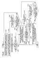
Fig. 26 is a flowchart of an individual phase andamplitude adjustment process 2 in the modification of the fourth embodiment. - With reference to the drawings, embodiments of the present invention will be described next.
- First Embodiment
Fig. 5 shows the structure of a power seriesdigital predistorter 100 of a first embodiment of the present invention and its peripheral equipment. The peripheral equipment shown inFig. 5 includes a digital predistorterinput signal generator 990, anamplifier 950, and afeedback signal generator 960 which takes in a part of the output of theamplifier 950 and generates a feedback signal for the power seriesdigital predistorter 100. Theamplifier 950 and thefeedback signal generator 960 are the same as the peripheral equipment of thedigital predistorter 900, which has been described as the related art, and therefore, a repeated description will be omitted (see the foregoing description). - The digital predistorter
input signal generator 990 includes atransmission signal generator 991, apilot signal generator 992, and aswitch 993 for selecting the output of thetransmission signal generator 991 or the output of thepilot signal generator 992. The digital input transmission signal output from thetransmission signal generator 991 includes desired information. The pilot signal output by thepilot signal generator 992 is used when frequency characteristic compensator coefficients, which will be described later, are determined. The frequency and the like of the pilot signal are not especially limited. In the first embodiment, the digital input transmission signal and the pilot signal include the I-phase signal and the Q-phase signal (I/Q signals) each. - The power series
digital predistorter 100 in the first embodiment includes alinear transfer path 101A, an N-th orderdistortion generation path 101B,dividers 102,combiners 103, digital-to-analog converters (DACs) 104, analog-to-digital converters (ADCs) 105, adistortion observer 106, and acontroller 107. Thelinear transfer path 101A includes a delay unit 101A1. The N-th orderdistortion generation path 101B includes an N-th order distortion generator 101B1, an N-th order distortion vector adjuster 101B2, and an N-th order frequency characteristic compensator 101B3. Thedividers 102 divide the I-phase signal and the Q-phase signal into thelinear transfer path 101A and the N-th orderdistortion generation path 101B. Thecombiners 103 combine the outputs of thelinear transfer path 101A and the outputs of the N-th orderdistortion generation path 101B for the I-phase signal and the Q-phase signal. The digital-to-analog converters (DACs) 104 convert the I-phase signal and the Q-phase signal output from the combiners 103 (digital I/Q signals with distortion compensation signals added thereto) separately to analog I/Q signals. The analog-to-digital converters (ADCs) 105 convert the outputs (analog I/Q signals) of thefeedback signal generator 960 which takes in a part of the output of theamplifier 950 as the feedback signal, to digital I/Q signals. Thedistortion observer 106 observes the outputs (digital I/Q signals) of theADCs 105 and measures the power in the transmission signal band and the power of the N-th order distortion component generated by theamplifier 950 in bands divided by the N-th order frequency characteristic compensator 101B3. Thecontroller 107 adjusts the vector coefficients (amplitude and phase) to be set in the N-th order distortion vector adjuster 101B2 and one or more frequency characteristic compensator coefficients (amplitude and phase) to be set in the N-th order frequency characteristic compensator 101B3, in accordance with the output of thedistortion observer 106. Here, N is a predetermined odd number equal to or larger than 3. In this example, N is 3. - The
controller 107 includes aphase setting unit 1071, anamplitude setting unit 1072, and a processing control unit 1073 (seeFig. 6 ). Thephase setting unit 1071 sets the phase adjustment amounts of M distortion component bands collectively in the third-order frequency characteristic compensator 101B3. Theamplitude setting unit 1072 sets the amplitude adjustment amounts of M distortion component bands (M is a predetermined integer equal to or larger than 2) collectively in the third-order frequency characteristic compensator 101B3. Theprocessing control unit 1073 judges whether an index (ACLR, for example, as described later) indicating the degree of cancellation of the distortion component generated by thepower amplifier 953 satisfies a predetermined condition (lower than or lower than or equal to the target value). If the condition is not satisfied, thephase setting unit 1071 is controlled to set the phase adjustment amounts again, and theamplitude setting unit 1072 is controlled to set the amplitude adjustment amounts again. - In the first embodiment, just the third-order distortion component is the target of compensation. If one or more different W-th order distortion generation paths (W is an odd number equal to or larger than 5) are connected in parallel to the third-order
distortion generation path 101B, a plurality of odd-order distortion components can become the compensation target. - The third-order frequency characteristic compensator 101B3 converts the outputs of the third-order distortion vector adjuster 101B2 into the frequency domain and divides the upper and lower third-order distortion component bands into M parts, as shown in
Fig. 3 . The third-order frequency characteristic compensator 101B3 includes a serial-to-parallel converter (S/P) 101B31, a fast Fourier transformer (FFT) 101B32, a complex multiplier (C.M.) 101B33, an inverse fast Fourier transformer (IFFT) 101B34, and a parallel-to-serial converter (P/S) 101B35. The S/P 101B31 converts the outputs of the third-order distortion vector adjuster 101B2 from serial to parallel. The FFT 101B32 converts the outputs of the S/P 101B31 into the frequency domain. The complex multiplier 101B33 adjusts the phase and amplitude by multiplying them by the frequency characteristic compensator coefficients given by thecontroller 107 in each of the M divided bands. The IFFT 101B34 converts the outputs of the complex multiplier 101B33 into the time domain. The P/S 101B35 converts the outputs of the IFFT 101B34 from parallel to serial. The third-order frequency characteristic compensator 101B3 adjusts the phase and amplitude in each of the M divided bands by using the frequency characteristic compensation coefficients (phase and amplitude) specified by thecontroller 107. - The input signals of the
digital predistorter 100 are the outputs (pilot signals) of thepilot signal generator 992 until the third-order distortion components are minimized (to the target value or below). After the third-order distortion components are minimized (to the target value or below), theswitch 993 selects the outputs (transmission signals) of thetransmission signal generator 991 as the input signals. - With reference to
Fig. 7 , the flow of processing performed by thecontroller 107 to set the phase adjustment amount and the amplitude adjustment amount of each of the M bands in the third-order frequency characteristic compensator 101B3 will be described. An example of using a OFDM signal as the transmission signal will be described next. The OFDM signal comprises 64 subcarriers with signal bandwidth of 3.84 MHz, and a route roll off rate of 0.22. The modulation scheme for each subcarrier is QPSK. The bandwidth, route roll off rate, the number of subcarriers, subcarrier modulation scheme, and the like can be specified as needed. The transmission signal can be specified appropriately for the signal to be amplified by theamplifier 950 and can be the WCDMA signal, for example. The adjacent channel leakage power ratio (ACLR) is used as an index for judging the degree of distortion compensation (index indicating the degree of cancellation of the distortion component generated by the power amplifier). As shown inFig. 8 , the ACLR here is the ratio of the power in the upper and lower bands of third-order distortion component (3.84 MHz-bandwidth) at ±5 MHz offset from the center frequency to the power in the transmission signal band (3.84 MHz-bandwidth). The offset from the center frequency and the third-order distortion component band can be specified appropriately for the bandwidth of the transmission signal. The distortion compensation judgment index used in the first embodiment is ACLR, and the upper or lower band of third-order distortion component can also be used as the index. - The phase adjustment amount and amplitude adjustment amount of the third-order distortion vector adjuster 101B2 are considered to have been specified appropriately by a known method. If the power of the third-order distortion component band is used as an index, for example, the
controller 107 sets a phase adjustment amount and amplitude adjustment amount in the third-order distortion vector adjuster 101B2 such that the power of the upper or lower band of third-order distortion component is minimized (reaches the target value). One method for determining the phase adjustment amount and amplitude adjustment amount is a perturbation method (see Toshio Nojima, Yoshiharu Okamoto, Satoshi Oyama, "Predistortion Nonlinear Compensator for Microwave SSB-AM System", IEICE Transactions, Vol. J67-B, No. 1, Jan. 1984). When the phase adjustment amount is determined by using the perturbation method, the power of the third-order distortion component band is measured when the phase adjustment amount is set to those immediately larger and smaller than the phase adjustment amount set first; the phase adjustment amount is changed by an offset value in the direction in which the power of the third-order distortion component band decreases; and the power of the third-order distortion component band is measured. By changing the phase adjustment amount and measuring the power of the third-order distortion component band repeatedly, the phase adjustment amount that minimizes the power of the third-order distortion component band is obtained. The same process can be applied to the amplitude. Although thecontroller 107 has a functional element to set the phase adjustment amount and amplitude adjustment amount in the third-order distortion vector adjuster 101B2, the process of setting the phase adjustment amount and amplitude adjustment amount in the third-order distortion vector adjuster 101B2 is carried out prior to and independently of the process of setting a phase adjustment amount and an amplitude adjustment amount in the third-order frequency characteristic compensator 101B3. Therefore, the functional element is not shown in the figure. - Process for Controlling Phase Adjustment Amount and Amplitude Adjustment Amount
Thephase setting unit 1071 of thecontroller 107 sets the phase adjustment amounts of the M distortion component bands collectively in the third-order frequency characteristic compensator 101B3 (collective phase adjustment process in step S101). Theamplitude setting unit 1072 of thecontroller 107 sets the amplitude adjustments of the M distortion component bands collectively in the third-order frequency characteristic compensator 101B3 (collective amplitude adjustment process in step S102). Thedistortion observer 106 measures the power in the transmission signal band and the power in the M distortion component bands and obtains an ACLR (ACLR measurement process in step S103). Theprocessing control unit 1073 of thecontroller 107 repeats steps S101 to S103 until the measured ACLR falls below the target value (ACLR judgment process in step S104). Here, the phase adjustment amounts of the M distortion component bands are specified collectively. Then, the amplitude adjustment amounts of the M distortion component bands are specified collectively. This is because the increase or decrease in the distortion component corresponding to the change in phase is generally larger than the increase or decrease in the distortion component corresponding to the change in amplitude. Somepower amplifiers 953, however, have a larger increase or decrease in the distortion component corresponding to the change in amplitude than the increase or decrease in the distortion component corresponding to the change in phase. In that case, it is preferable to specify the amplitude adjustment amounts of the M distortion component bands collectively and then specify the phase adjustment amounts of the M distortion component bands collectively. - The collective phase adjustment process of the
controller 107 will be described (this process will be referred to as collective phase adjustment process 1). In the description given below, the phase adjustment amount to be specified in each of the M divided bands of the third-order frequency characteristic compensator 101B3 will be denoted by Xm (0 < m ≤ M), and the distortion component power in the divided band will be denoted by Dm. - With reference to J. Ohkawara, Y. Suzuki, and S. Narahashi, "Fast Calculation Scheme for Frequency Characteristic Compensator of Digital Predistortion Linearizer," IEEE Vehicular Technology Conference Spring 2009, proceedings, April 2009, the relationship between the distortion component and the phase adjustment amount to be set in the third-order frequency characteristic compensator and the relationship between the distortion component and the amplitude adjustment amount to be set in the third-order frequency characteristic compensator will be described.
Fig. 9 shows an equivalent low-pass system model of the digital predistorter and power amplifier. The power amplifier is formed of an amplification path and a third-order distortion generation path. Here, s(t) denotes the input signal of the digital predistorter; α and β respectively denote the amplitude and phase of the third-order distortion vector adjuster in the digital predistorter; g(t) denotes the impulse response of the third-order frequency characteristic compensator in the digital predistorter; r1 denotes the gain of the amplification path in the power amplifier; r3 and θ respectively denote the gain and phase of the third-order distortion generation path in the power amplifier; and h(t) denotes the impulse response indicating the frequency dependence of the third-order distortion component in the power amplifier. - The output signal z(t) of the power amplifier can be expressed as follows.

The asterisk (*) indicates convolution. - With respect to just the third-order distortion component in Equation (1), the distortion component e(t) can be expressed as follows.

Equation (2) converted into the frequency domain is as follows.
Here, E(f), H(f), G(f), and S3(f) are L-point discrete Fourier transforms of e(t), h(t), g3(t), and s3(t), respectively. The frequency characteristic Hm of the distortion component in the divided band m of the third-order frequency characteristic compensator is expressed as follows.
The third-order frequency characteristic compensator coefficient Gm is expressed as given below.
Here, Ym is the amplitude adjustment amount in the divided band m of the third-order frequency characteristic compensator. From Equations (3) to (5), the power Dm of the distortion component in the divided band m is expressed as follows.
Equation (6) indicates that if Ym is a constant Ym(0), Dm is minimized when cos(θ + φm - β - Xm) = -1. Therefore, by the Taylor expansion around Xm = θ + φm - β - π, the relationship between Xm and Dm can be approximated by the equation given below:
where


From Equation (7), Dm can be expressed by a quadratic function using Xm. When the coefficients (a2,m, a1,m, a0,m) of the quadratic function are obtained, Xmin,m that minimizes the distortion component can be calculated. The amplitude will be described next. From Equation (7), the relationship between Ym and Dm when Xm is a constant Xm(0) can be expressed as given below:
where


From Equation (8), Dm can be expressed by a quadratic function using Ym. Like Xm, Ymin,m that minimizes the distortion component can be calculated if the coefficients (b2,m, b1,m, b0,m) of the quadratic function are obtained. - Collective
Phase Adjustment Process 1
Fig. 10 shows a flowchart illustrating the collectivephase adjustment process 1. Thephase setting unit 1071 of thecontroller 107 sets initial phase adjustment amounts X1 to XM collectively in the third-order frequency characteristic compensator 101B3 (phase step S11p). Thedistortion observer 106 measures the powers D1 to DM of the distortion component bands simultaneously (phase step S12p). - The method of measuring the power of the distortion component will be described next. The output signal of the
amplifier 950 is converted to analog I/Q signals by thefeedback signal generator 960, and the analog I/Q signals are converted to digital I/Q signals by theADCs 105. Thedistortion observer 106 converts the digital I/Q signals from serial to parallel, then multiplies them by a window function (such as the Hamming window), and performs the discrete Fourier transform. Because the spectrum of the distortion component can be obtained collectively from the result of the discrete Fourier transform, thedistortion observer 106 measures the powers D1 to DM of the distortion component collectively from the results of the discrete Fourier transform. Theconventional distortion observer 906 observes the power of a specified band only. Thedistortion observer 106 in the first embodiment measures the powers D1 to DM of the M distortion component bands collectively. - The
phase setting unit 1071 of thecontroller 107 records the set phase adjustment amount Xm and the measured power Dm as R1m,11 and R2m,11 (0 < 11 ≤ L1) in each band (phase step S13p). Thephase setting unit 1071 of thecontroller 107 adds predetermined offset values A11 to A1M (positive values) to the phase adjustment amounts X1 to XM and sets the new phase adjustment amounts X1 to XM collectively in the third-order frequency characteristic compensator 101B3 (phase step S14p). Thephase setting unit 1071 of thecontroller 107 repeats the phase steps S12p to S14p L1 times (L1 is an integer equal to or larger than 3) (phase step S15p). In the phase step S 14p, negative offset values may be added to the phase adjustment amounts. Instead of adding or subtracting positive offset values to or from the phase adjustment amounts in all the distortion component bands, there may be bands in which a positive offset value is added to the phase adjustment amount and bands in which a negative offset value is added to the phase adjustment amount. For example, a positive offset value may be added to the phase adjustment amount in odd-numbered distortion compensation bands, and a negative offset value may be added to the phase adjustment amount in even-numbered distortion compensation bands. The process may be modified such that, if the judgment made in the phase step S15p is No, the phase step S14p is executed. - If the phase steps S12p to S14p are executed L1 times, the
phase setting unit 1071 of thecontroller 107 specifies the coefficients (a2,m, a1,m, a0,m) of the quadratic function (Dm = a2,mX2 m + a1,mXm + a0,m) representing the relationship between the phase adjustment amount Xm and the distortion component Dm, by using R1m,11 and R2m,11, by the least squares method (phase step S16p). Then, thephase setting unit 1071 of thecontroller 107 calculates the phase adjustment amount Xmin,m that minimizes the quadratic function, as -a1,m/(2a2,m) (phase step S17p). Thephase setting unit 1071 of thecontroller 107 repeats the phase steps S16p and S 17p until the phase adjustment amount Xmin,m is calculated in all the distortion component bands (phase step S18p). After calculating the phase adjustment amount Xmin,m in all the distortion component bands, thephase setting unit 1071 of thecontroller 107 sets the phase adjustment amounts Xmin,1 to Xmin,M collectively in the third-order frequency characteristic compensator 101B3 (phase step S19p). - The relationship between the phase adjustment amount and the distortion component can be represented by a quadratic function by using the Taylor expansion on Equation (7), as descried earlier. The relationship between the phase adjustment amount and the distortion component may be represented by a cosine function (Dm = c2,mcos(c1,m - Xm) + c0,m), without using the Taylor expansion, and the coefficients (c2,m c1,m, c0,m) may be specified by using the least squares method in the phase step S16p, where


- In the phase step S17p, Xm is calculated so that Dm is minimized with the specified coefficients (c2,m, c1,m, c0,m). For example, if Xm is in radians, Xmin,m is calculated as π - c1,m. Since the cosine function is used instead of approximation by the Taylor expansion, the relationship between the phase adjustment amount and the distortion component may be represented more accurately than when the quadratic function is used. The distortion compensation amount obtained by using the cosine function becomes larger than that obtained by using the quadratic function, and it may be possible to reach the target value with a smaller number of repetitions. Instead of the cosine function, a sine function can be used by utilizing the supplementary angle formula. In other embodiments described later, the relationship between the phase adjustment amount and the distortion component may be a cosine function.
- The collective amplitude adjustment process in the
controller 107 is as illustrated by a flowchart shown inFig. 11 (this process will be referred to as collective amplitude adjustment process 1). In the following description, the amplitude adjustment amount to be specified in each of the M divided bands of the third-order frequency characteristic compensator 101B3 will be denoted by Ym. - Collective
Amplitude Adjustment Process 1
Theamplitude setting unit 1072 of thecontroller 107 sets initial amplitude adjustment amounts Y1 to YM collectively in the third-order frequency characteristic compensator 101B3 (amplitude step S11a). Thedistortion observer 106 measures the distortion component powers D1 to DM simultaneously (amplitude step S12a). Theamplitude setting unit 1072 of thecontroller 107 records the set amplitude adjustment amount Ym and the measured power Dm as R3m,12 and R4m,12 (0 < 12 ≤ L2) in each band (amplitude step S13a). Theamplitude setting unit 1072 of thecontroller 107 adds predetermined offset values B11 to B1M (positive values) to the amplitude adjustment amounts Y1 to YM and sets the new amplitude adjustment amounts Y1 to YM collectively in the third-order frequency characteristic compensator 101B3 (amplitude step S14a). Theamplitude setting unit 1072 of thecontroller 107 repeats the amplitude steps S12a to S14a L2 times (L2 is an integer equal to or larger than 3) (amplitude step S15a). In the amplitude step S14a, if the amplitude is larger than 0, a negative offset value may be added to the amplitude adjustment amount. Instead of adding or subtracting positive offset values to or from the amplitude adjustment amounts in all the distortion component bands, there may be bands in which a positive offset value is added to the amplitude adjustment amount and bands in which a negative offset value is added to the amplitude adjustment amount. For example, a positive offset value may be added to the amplitude adjustment amount in odd-numbered distortion compensation bands, and a negative offset value may be added to the amplitude adjustment amount in even-numbered distortion compensation bands. The process may be modified such that, if the judgment made in the amplitude step S15a is No, the amplitude step S 14a is executed. - If the amplitude steps S12a to S14a are executed L2 times, the
amplitude setting unit 1072 of thecontroller 107 specifies the coefficients (b2,m, b1,m, b0,m) of the quadratic function (Dm = b2,mY2 m + b1,mYm + b0,m) representing the relationship between the amplitude adjustment amount Ym and the distortion component Dm, by using R3m,12and R4m,12, by the least squares method (amplitude step S16a). Then, theamplitude setting unit 1072 of thecontroller 107 calculates the amplitude adjustment amount Ymin,m that minimizes the quadratic function, as -b1,m/(2b2,m) (amplitude step S17a). Theamplitude setting unit 1072 of thecontroller 107 repeats the amplitude steps S16a and S17a until the amplitude adjustment amount Ymin,m is calculated in all the distortion component bands (amplitude step S18a). After calculating the amplitude adjustment amount Ymin,m in all the distortion component bands, theamplitude setting unit 1072 of thecontroller 107 sets the amplitude adjustment amounts Ymin,i to Ymin,M collectively in the third-order frequency characteristic compensator 101B3 (amplitude step S19a). - The results of an experiment in the first embodiment will be described next. In the experiment, a 2-GHz 1W-class amplifier (output backoff 12.4 dB) was used. The upper and lower bands of third-order distortion component were divided into two equal parts (M = 4) respectively, and the bands were marked with
numbers 1 to 4 from the low frequency side (seeFig. 12 ). L1 and L2 were both 3. The target ACLR value was -45 dBc in the experiment. A comparative experiment was carried out on the conventional control method (Method A), which adjusts phase and amplitude in one band after another.Fig. 13 shows the time needed to set phases, for example, by the method A and the control method in the first embodiment (method B). InFig. 13 , (1) indicates the processing time for setting the phase adjustment amount and measuring the distortion component; (2) indicates the time needed to calculate the phase adjustment amount that minimizes the quadratic function; and (3) indicates the processing time for setting the calculated phase adjustment amount. The periods (1), (2), and (3) are equally sized inFig. 13 for the sake of simplicity, but they actually differ in size. As shown inFig. 13 , the processes corresponding to (1) to (3) are executed for one band after another in method A, whereas the processes are executed for all the distortion component bands collectively in method B. The phase adjustment amounts can be determined more quickly by method B than by method A. -
Fig. 14A shows a spectrum (marked by "without frequency characteristic compensator") before phase adjustment amounts and amplitude adjustment amounts are set in the third-order frequency characteristic compensator 101B3, a spectrum when method A is used, and a spectrum when method B is used.Fig. 14B shows the upper and lower ACLRs for the normalized time. The setting times in methods A and B were normalized separately on the horizontal axis with reference to the period required to specify the phase adjustment amounts and amplitude adjustment amounts that reduce the distortion component to the minimum level (target level) in all the bands by method A.Fig. 14A shows that the distortion compensation amount in the lower spectrum by method B is smaller than that by method A.Fig. 14B shows that both the upper ACLR and the lower ACLR are below the target value in methods A and B. Here, the normalized time of method B is 0.28, and the normalized time of method A is 1.0. This means that method B reduces the setting time by 72% compared with the conventional control method A. - The collective phase adjustment process by the
controller 107 may be as illustrated in a flowchart shown inFig. 15 (this process will be referred to as collective phase adjustment process 2). - Collective
Phase Adjustment Process 2
Thecontroller 107 sets initial phase adjustment amounts X1 to XM collectively in the third-order frequency characteristic compensator 101B3 (phase step S21p). Thedistortion observer 106 measures the distortion component powers D1 to DM simultaneously (phase step S22p). Thecontroller 107 compares the distortion component power Dm with a recorded value R5m in each band (phase step S23p). If the distortion component power becomes smaller than the recorded value in one band at least, thecontroller 107 records the phase adjustment amount Xm and the distortion component power Dm in the band where the distortion component power Dm is lower than the recorded value R5m as Xmm, m and as the recorded value R5m, respectively (phase step S24p). The initial value of the recorded value R5m is set to a value higher than the highest distortion component power Dm that can be measured. This causes the phase step S24p to be executed at least once in all the bands and the phase adjustment amount Xmin,m to be recorded in all the bands. Thecontroller 107 adds the offset value A2m (A2m > 0) to the phase adjustment amount Xm, sets the new phase adjustment amount in the band where the distortion component power Dm is lower than the recorded value R5m (phase step S25p), and returns to the phase step S22p. In that step, a negative offset value may be added to the phase adjustment amount. If the distortion component power is equal to or higher than the recorded value in all the bands, thecontroller 107 sets the recorded phase adjustment amounts Xmm,1 to Xmim,M collectively in the third-order frequency characteristic compensator 101B3 (phase step S26p). - The collective amplitude adjustment process by the
controller 107 may be as illustrated in a flowchart shown inFig. 16 (this process will be referred to as collective amplitude adjustment process 2). - Collective
Amplitude Adjustment Process 2
Thecontroller 107 sets initial amplitude adjustment amounts Y1 to YM collectively in the third-order frequency characteristic compensator 101B3 (amplitude step S21a). Thedistortion observer 106 measures the distortion component powers D1 to DM simultaneously (amplitude step S22a). Thecontroller 107 compares the distortion component power Dm with a recorded value R6m in each band (amplitude step S23a). If the distortion component power is smaller than the recorded value in one band at least, thecontroller 107 records the amplitude adjustment amount Ym and the distortion component power Dm in the band where the distortion component power Dm is lower than the recorded value R6m as Ymin,m and recorded value R6m, respectively (amplitude step S24a). The initial value of the recorded value R6m is set to a value higher than the highest distortion component power Dm that can be measured. This causes the amplitude step S24a to be executed at least once in all the bands and the amplitude adjustment amount Ymin,m to be recorded in all the bands. Thecontroller 107 adds the offset value B2m (B2m > 0) to the amplitude adjustment amount Ym, sets the new amplitude adjustment amount in the band where the distortion component power Dm is lower than the recorded value R6m (amplitude step S25a), and returns to the amplitude step S22a. In that step, if the amplitude adjustment amount Ym is larger than 0, a negative offset value may be added to the amplitude adjustment amount. If the distortion component power is equal to or higher than the recorded value in all the bands, thecontroller 107 sets the recorded amplitude adjustment amounts Ymin,1 to Ymin,M collectively in the third-order frequency characteristic compensator 101B3 (amplitude step S26a). - In the first embodiment, after the collective phase adjustment process is repeated, the collective amplitude adjustment process may be repeated, and then the ACLR measurement may be performed. If the collective
phase adjustment process 1 and the collectiveamplitude adjustment process 1 are used, the first phase adjustment amount is specified such that the phase adjustment amount that minimizes the quadratic function becomes the median among the L1 phase adjustment amounts. The offset value may be changed to 2/3 times, 1/2 times, or the like, or may not be changed. The amplitude adjustment amounts are specified in the same manner as the phase adjustment amounts. If the collectivephase adjustment process 2 and the collectiveamplitude adjustment process 2 are used, the phase adjustment amount offset values and the amplitude adjustment amount offset values are changed to 2/3 times, 1/2 times, or the like, respectively. - In the first embodiment, when the collective
phase adjustment process 1 is used, the collectiveamplitude adjustment process 1 is used together therewith, but the collectiveamplitude adjustment process 2 may be used. When the collectivephase adjustment process 2 is used, the collectiveamplitude adjustment process 2 is used together therewith, but the collectiveamplitude adjustment process 1 may be used. - If the power of the transmission signal increases or decreases, the distortion component may increase. For that increase, a lookup table may be provided so that the phase adjustment amounts and amplitude adjustment amounts of the third-order frequency characteristic compensator 101B3 can be specified appropriately for the transmission signal power. The lookup table stores the phase adjustment amounts and amplitude adjustment amounts to be set in the third-order frequency characteristic compensator 101B3 on the basis of the transmission signal power. The phase adjustment amounts and amplitude adjustment amounts to be stored are obtained in accordance with the transmission signal power, through the processes described earlier. The
distortion observer 106 measures the transmission signal power, and thecontroller 107 references the lookup table to set phase adjustment amounts and amplitude adjustment amounts suitable for the transmission signal power in the third-order frequency characteristic compensator 101B3. - The processes in the first embodiment do not depend on the order of the distortion in the
distortion generation path 101B. If there are a plurality ofdistortion generation paths 101B, the processes described earlier should be performed in onedistortion generation path 101B after another. If there are a third-order distortion generation path and a fifth-order distortion generation path and if a third-order distortion vector adjuster and a fifth-order distortion vector adjuster are controlled appropriately, for example, the phase adjustment amounts and amplitude adjustment amounts of all the bands to be set in the third-order frequency characteristic compensator should be adjusted in the processes described earlier, and the phase adjustment amounts and amplitude adjustment amounts of all the bands to be set in the fifth-order frequency characteristic compensator should be adjusted in the same way. The adjustment for the fifth-order frequency characteristic compensator may be followed by the adjustment for the third-order frequency characteristic compensator. - Second Embodiment
Fig. 17 shows a flowchart illustrating processing in a second embodiment of the present invention. In the second embodiment, the following processes are added at the transition from the ACLR judgment process to the collective phase adjustment process, in the first embodiment: a process for recording the measured ACLR and the phase adjustment amounts and amplitude adjustment amounts set in the third-order frequency characteristic compensator 101B3 (ACLR, phase, and amplitude recording process in step S105) and a process for determining whether processes (collective phase adjustment process, collective amplitude adjustment process, and ACLR measurement process) have been repeated a specified number of times (first repetition judgment process in step S106). If the processes (collective phase adjustment process, collective amplitude adjustment process, and ACLR measurement process) have not been repeated the specified number of times, thecontroller 107 proceeds to the collective phase adjustment process described in the first embodiment. If the processes (collective phase adjustment process, collective amplitude adjustment process, and ACLR measurement process) have been repeated the specified number of times, thecontroller 107 collectively sets the phase adjustment amounts and amplitude adjustment amounts that have provided the minimum ACLRs of the ACLRs recorded in the ACLR, phase, and amplitude recording process, in all the bands of the third-order frequency characteristic compensator 101B3 (S107). - According to the second embodiment, even if the ACLR does not fall below the target value, the phase adjustment amounts and amplitude adjustment amounts that provide the smallest ACLRs among the ACLRs obtained in the processes repeated the specified number of times can be set in the third-order frequency characteristic compensator 101B3 without generating an endless loop.
- In the second embodiment, ACLRs are recorded. If the index of the distortion compensation amount in the third-order frequency characteristic compensator 101B3 is the power of the distortion component, the distortion component power is recorded instead of the ACLR in the ACLR, phase, and amplitude recording process (S105). In that case, the
controller 107 collectively sets the phase adjustment amounts and amplitude adjustment amounts corresponding to the smallest distortion component powers among the recorded distortion component powers, in all the bands of the third-order frequency characteristic compensator 101B3. - According to the present invention, since the phases and amplitudes in all the distortion component bands are set collectively in the frequency characteristic compensator, the frequency characteristic compensator coefficients (phase and amplitude) can be adjusted quickly, as clearly indicated by the first embodiment.
- Third Embodiment
In a third embodiment described below, since the adjustment time can be reduced more than before, processes for high-precision distortion compensation are carried out.Fig. 18 shows a flowchart of processing in the third embodiment of the present invention. The third embodiment differs from the second embodiment in that, when it is judged in the first repetition judgment process S106 that the processes have been repeated the specified number of times, it is judged whether the collective phase adjustment process and the collective amplitude adjustment process have been modified once (modification judgment process in step S106a). If no modification has been made, the collective phase adjustment process and the collective amplitude adjustment process are modified together (process for modifying the collective phase adjustment process and the collective amplitude adjustment process in step S106b). If processing in the second embodiment is performed in a first stage in accordance with the collectivephase adjustment process 1 and the collectiveamplitude adjustment process 1 described in the first embodiment, processing in the next stage of the second embodiment is performed in accordance with the collectivephase adjustment process 2 and the collectiveamplitude adjustment process 2 described in the first embodiment. Using two different pairs of the collective phase adjustment process and the collective amplitude adjustment process can provide better distortion compensation than using a single pair of the collective phase adjustment process and the collective amplitude adjustment process. - For a case in which the ACLR does not fall below the target value just by changing the collective phase adjustment process and the collective amplitude adjustment process once each or for distortion compensation with higher precision, three or more different pairs of the collective phase adjustment process and the collective amplitude adjustment process may be prepared.
- The collective phase adjustment process and the collective amplitude adjustment process need not be changed together; just one process may be changed. For example, in the first stage, processing in the second embodiment is performed in accordance with the collective
phase adjustment process 1 and collectiveamplitude adjustment process 1 described in the first embodiment; in the second stage, processing in the second embodiment is performed in accordance with the collectivephase adjustment process 1 and collectiveamplitude adjustment process 2 described in the first embodiment; in the third stage, processing in the second embodiment is performed in accordance with the collectivephase adjustment process 2 and collectiveamplitude adjustment process 1 described in the first embodiment; and in the final stage, processing in the second embodiment is performed in accordance with the collectivephase adjustment process 2 and collectiveamplitude adjustment process 2 described in the first embodiment. - Fourth Embodiment
A fourth embodiment differs from the second embodiment in that the phase adjustment amounts and amplitude adjustment amounts are set individually if ACLR does not fall below the target value even after the processes (collective phase adjustment process, collective amplitude adjustment process, and ACLR measurement process) are repeated the specified number of times.Fig. 19 shows a flowchart illustrating processing in the fourth embodiment. The difference from the second embodiment is that, if it is judged in the first repetition judgment process in step S106 shown inFig. 19 that the processes (collective phase adjustment process, collective amplitude adjustment process, and ACLR measurement process) have been repeated the specified number of times, the phase adjustment amount is adjusted in one band after another (individual phase adjustment process in step S108); the amplitude adjustment amount is adjusted in one band after another (individual amplitude adjustment process in step S109); the ACLR measurement process in step (S110) is carried out; and except when the ACLR falls below the target value (S111), the individual phase adjustment process to the ACLR measurement process (S 108 to S110) are repeated in that order up to a specified number of times (second repetition judgment process in step S113). Prior to the second repetition judgment process in step S113, an ACLR, phase, and amplitude recording step S112, which is the same as the ACLR, phase, and amplitude recording step S105 described in the second embodiment, is performed. If the ACLR does not fall below the target value after the individual phase adjustment process S108 to the ACLR measurement process S110 are repeated, thecontroller 107 collectively sets the phase adjustment amounts and amplitude adjustment amounts corresponding to the minimum ACLRs among the measured ACLRs in the third-order frequency characteristic compensator 101B3. The repetition count judged in the second repetition judgment process in step S113 may or may not be the same as the repetition count judged in the first repetition judgment process in step S106. - In the fourth embodiment, after the phase adjustment amounts are adjusted, the amplitude adjustment amounts are adjusted. This is because the increase or decrease in the distortion component corresponding to the change in phase is generally larger than the increase or decrease in the distortion component corresponding to the change in amplitude. In some
power amplifiers 953, however, the increase or decrease in the distortion component corresponding to the change in amplitude is larger than the increase or decrease in the distortion component corresponding to the change in phase. In that case, the phase adjustment and amplitude adjustment may be performed in reverse order. - The individual phase adjustment process will be described next with reference to
Fig. 20 (this process will be referred to as individual phase adjustment process 1). - Individual
Phase Adjustment Process 1
Thecontroller 107 sets the phase adjustment amount Xm in the band m (phase step S31p). Thedistortion observer 106 measures the distortion component power Dm in the band m (phase step S32p). Thecontroller 107 records the set phase adjustment amount Xm and the measured power Dm as R7m,13 and R8m,13 (0 < 13 ≤ L3), respectively (phase step S33p). Thecontroller 107 adds an offset value A3m (A3m > 0) to the phase adjustment amount Xm and sets the new phase adjustment amount Xm in the band m (phase step S34p). Thecontroller 107 repeats the phase steps S32p to S34p L3 times (L3 is an integer equal to or larger than 3) (phase step S35p). In the phase step S34p, a negative offset value may be added to the phase adjustment amount. When the phase steps S32p to S34p are executed L3 times, thecontroller 107 specifies the coefficients (a2,m, a1,m, a0,m) of a quadratic function (Dm = a2,mX2 m + a1,mXm + a0,m) representing the relationship between the phase adjustment amount Xm and the distortion component Dm, by using R7m,13 and R8m,13, by the least squares method (phase step S36p). Thecontroller 107 calculates the phase adjustment amount Xmin,m that minimizes the quadratic function, as -a1,m/(2a2,m) (phase step S37p). Thecontroller 107 sets the obtained phase adjustment amount Xmin,m in the third-order frequency characteristic compensator 101B3 (phase step S38p). Thecontroller 107 repeats the phase steps S31p to S38p until the phase adjustment amount Xmin,m is set in all the distortion component bands (phase step S39p). The process may be changed such that, if judgment made in the phase step S35p is No, the phase step S34p is executed. - If the individual
phase adjustment process 1 is performed, the individual amplitude adjustment process is performed as illustrated in a flowchart shown inFig. 21 (this process will be referred to as individual amplitude adjustment process 1). - Individual
Amplitude Adjustment Process 1
Thecontroller 107 sets the amplitude adjustment amount Ym in the band m (amplitude step S31a). Thedistortion observer 106 measures the distortion component power Dm in the band m (amplitude step S32a). Thecontroller 107 records the set amplitude adjustment amount Ym and the measured power Dm as R9m,14 and R10m,14 (0 < 14 ≤ L4) (amplitude step S33a). Thecontroller 107 adds an offset value B3m (B3m > 0) to the amplitude adjustment amount Ym and sets the new amplitude adjustment amount Ym in the band m (amplitude step S34a). The amplitude steps S31a to S34a are repeated L4 times (L4 is an integer equal to or larger than 3) (amplitude step S35a). When the amplitude adjustment amount is larger than 0, a negative offset value may be added to the amplitude adjustment amount in the amplitude step S34a. When the amplitude steps S32a to S34a are executed L4 times, thecontroller 107 specifies the coefficients (b2,m, b1,m, b0,m) of a quadratic function (Dm = b2,mY2 m + b1,mYm + b0,m) representing the relationship between the amplitude adjustment amount Ym and the distortion component Dm, by using R9m,14 and R10m,14, by the least squares method (amplitude step S36a). Thecontroller 107 calculates the amplitude adjustment amount Ymin,m that minimizes the quadratic function, as -b1,m/(2b2,m) (amplitude step S37a). Thecontroller 107 sets the obtained amplitude adjustment amount Ymin,m in the third-order frequency characteristic compensator 101B3 (amplitude step S38a). Thecontroller 107 repeats the amplitude steps S31a to S38a until the amplitude adjustment amount Ymin,m is set in all the distortion component bands (amplitude step S39a). - The individual phase adjustment process may be as illustrated in a flowchart shown in
Fig. 22 (this process will be referred to as individual phase adjustment process 2). - Individual
Phase Adjustment Process 2
Thecontroller 107 sets the phase adjustment amount Xm in the band m (phase step S41p). Thedistortion observer 106 measures the distortion component power Dm in the band m (phase step S42p). Thecontroller 107 compares the distortion component power Dm with a recorded value R11m (phase step S43p). If the distortion component power Dm falls below the recorded value R11m, thecontroller 107 records the phase adjustment amount Xm as Xmin,m and the distortion component power Dm as the recorded value R11m (phase step S44p). The initial value of the recorded value R11m is set to a value higher than the highest distortion component power Dm that can be measured. This causes the phase step S44p to be performed once at least and the phase adjustment amount Xmin,m to be recorded. Thecontroller 107 adds the offset value A4m (A4m > 0) to the phase adjustment amount Xm, sets the new phase adjustment amount Xm in the band m (phase step S45p), and returns to the phase step S42p. In that step, a negative offset value may be added to the phase adjustment amount. If the distortion component power Dm becomes equal to or higher than the recorded value R11m, thecontroller 107 sets the recorded phase adjustment amount Xmin,m in the band m (phase step S46p). Thecontroller 107 repeats the processes until the phase adjustment amount Xmin,m is set in all the distortion component bands (phase step S47p). - The individual amplitude adjustment process may be as illustrated in a flowchart shown in
Fig. 23 (this process will be referred to as individual amplitude adjustment process 2). - Individual
Amplitude Adjustment Process 2
Thecontroller 107 sets the amplitude adjustment amount Ym of the band m (amplitude step S41a). Thedistortion observer 106 measures the distortion component power Dm in the band m (amplitude step S42a). Thecontroller 107 compares the distortion component power Dm with a recorded value R12m (amplitude step S43a). If the distortion component power Dm is smaller than the recorded value R12m, thecontroller 107 records the amplitude adjustment amount Ym as Ymin,m and the distortion component power Dm as the recorded value R12m (amplitude step S44a). The initial value of the recorded value R12m is set to a value higher than the highest distortion component power Dm that can be measured. This causes the amplitude step S44a to be performed once at least and the amplitude adjustment value Ymin,m to be recorded. Thecontroller 107 adds the offset value B4m to the amplitude adjustment amount Ym, sets the new amplitude adjustment amount Ym in the band m (amplitude step S45a), and returns to the amplitude step S42a. If the amplitude adjustment amount is larger than 0, a negative offset value may be added to the amplitude adjustment amount. When the distortion component power Dm is equal to or larger than the recorded value R12m, thecontroller 107 sets the recorded amplitude adjustment amount Ymin,m in the band m (amplitude step S46a). Thecontroller 107 repeats the processes described above until the amplitude adjustment amount Ymin,m is set in all the distortion component bands (amplitude step S47a). - The fourth embodiment may be modified such that, in the collective adjustments made in all the bands as in the third embodiment, the collective phase adjustment process and/or the collective amplitude adjustment process is changed after the first repetition judgment process; and/or, in the adjustment made in one band after another, the individual phase adjustment process and/or the individual amplitude adjustment process is changed after the second repetition judgment process.
- Modification
A modification of the fourth embodiment will be described with reference toFig. 24 . This modification differs from the fourth embodiment in that the third-order frequency characteristic compensator 101B3 sets a phase adjustment amount and an amplitude adjustment amount in one band and then sets a phase adjustment amount and an amplitude adjustment amount in another band (S106c, S106d). In the modification, ACLR can be brought to a value smaller than the target value with a smaller number of repetitions than when the amplitude adjustment amounts are adjusted in all the bands after the phase adjustment amounts are adjusted in all the bands, as in the fourth embodiment. The phase adjustment and the amplitude adjustment may be made in that order or in reverse order. - The phase and amplitude adjustment process will be described with reference to
Fig. 25 (this process will be referred to as individual phase and amplitude adjustment process 1). The phase adjustment amount to be specified in each of M divided bands of the third-order frequency characteristic compensator 101B3 is denoted by Xm,15 (0 < m ≤ M, 0 < 15 ≤ L5); the amplitude adjustment amount is denoted by Ym,16 (0 < 16 ≤ L6); and the distortion component power in the divided band is denoted by Dm. - Individual Phase and
Amplitude Adjustment Process 1
Thecontroller 107 sets the phase adjustment amount Xm,15 in the band m (phase and amplitude step S51). Thedistortion observer 106 measures the distortion component power Dm in the band m (phase and amplitude step S52). Thecontroller 107 records the set phase adjustment amount Xm,15 and the measured power Dm as R13m,15 and R14m,15, respectively (phase and amplitude step S53). Thecontroller 107 repeats the phase and amplitude steps S51 to S53 until the distortion component power Dm is measured for L5 different phase adjustment amounts Xm,15 (L5 is an integer larger than 2) (phase and amplitude step S54). After the distortion component power Dm is measured for L5 different phases Xm,15, thecontroller 107 specifies the coefficients (a2,m, a1,m, a0,m) of a quadratic function (Dm = a2,mX2 m + a1,mXm + a0,m) representing the relationship between the phase adjustment amount Xm and the distortion component Dm, by using the recorded values R13m,15 and R14m,15, by the least squares method (phase and amplitude step S55). Thecontroller 107 calculates the phase adjustment amount Xmin,m that minimizes the quadratic function, as -a1,m/(2a2,m) (phase and amplitude step S56). Thecontroller 107 sets the obtained phase adjustment amount Xmin,m in the band m (phase and amplitude step S57). Then, thecontroller 107 sets the amplitude adjustment amount Ym,16 in the band m (phase and amplitude step S58). Thedistortion observer 106 measures the distortion component power Dm in the band m (phase and amplitude step S59). Thecontroller 107 records the set amplitude adjustment amount Ym,16 and the measured power Dm as R15m,16 and R16m,16, respectively (phase and amplitude step S60). Thecontroller 107 repeats the phase and amplitude steps S58 to S60 until the distortion component power Dm is measured for L6 different amplitude adjustment amounts Ym,16 (L6 is an integer larger than 2) (phase and amplitude step S61). After the distortion component power Dm is measured for L6 different amplitude adjustment amounts Ym,16, thecontroller 107 specifies the coefficients (b2,m, b1,m, b0,m) of a quadratic function (Dm = b2,mY2 m + b1,mYm + b0,m) representing the relationship between the amplitude adjustment amount Ym and the distortion component Dm, by using the recorded values R15m,16 and R16m,16, by the least squares method (phase and amplitude step S62). Thecontroller 107 calculates the amplitude adjustment amount Ymin,m that minimizes the quadratic function, as -b1,m/(2b2,m) (phase and amplitude step S63). Thecontroller 107 sets the obtained amplitude adjustment amount Ymin,m in the band m (phase and amplitude step S64). - The individual phase and amplitude adjustment process may be as illustrated in a flowchart shown in
Fig. 26 (this process will be referred to as individual phase and amplitude adjustment process 2). In the description given below, Xm (0 < m ≤ M) and Ym (0 < m ≤ M) respectively denote the phase adjustment amount and the amplitude adjustment amount to be specified in each of the M divided bands of the third-order frequency characteristic compensator 101B3. - Individual Phase and
Amplitude Adjustment Process 2
Thecontroller 107 sets the phase adjustment amount Xm in the band m (phase and amplitude step S71). Thedistortion observer 106 measures the distortion component power Dm in the band m (phase and amplitude step S72). Thecontroller 107 compares the distortion component power Dm with a recorded value R17m (phase and amplitude step S73). If the distortion component power Dm falls below the recorded value R17m, thecontroller 107 records the phase adjustment amount Xm as Xmin,m and the distortion component power Dm as R17m (phase and amplitude step S74). The initial value of R17m is set to a value higher than the highest distortion component power Dm that can be measured. This causes the phase and amplitude step S74 to be executed at least once and the phase adjustment amount Xmin,m to be recorded. Thecontroller 107 adds an offset value A5m to the phase adjustment amount Xm, sets the new phase adjustment amount Xm in the band m (phase and amplitude step S75), and returns to the phase amplitude step S72. If the distortion component power Dm becomes equal to or higher than R17m, thecontroller 107 sets the recorded phase adjustment amount Xmin,m in the band m (phase and amplitude step S76). Thecontroller 107 sets the amplitude adjustment amount Ym in the band m (phase and amplitude step S77). Thedistortion observer 106 measures the distortion component power Dm in the band m (phase and amplitude step S78). Thecontroller 107 compares the distortion component power Dm with a recorded value R18m (phase and amplitude step S79). If the distortion component power Dm becomes smaller than the recorded value R18m, thecontroller 107 records the amplitude adjustment amount Ym as Ymin,m and the distortion component power Dm as R18m (phase and amplitude step S80). The initial value of R18m is set to a value higher than the highest distortion component power Dm that can be measured. This causes the phase and amplitude step S80 to be performed at least once and the amplitude adjustment amount Ymin,m to be recorded. Thecontroller 107 adds an offset value B5m to the amplitude adjustment amount Ym, sets the new amplitude adjustment amount Ym in the band m (phase and amplitude step S81), and returns to the phase and amplitude step S78. If the distortion component power Dm becomes equal to or higher than R18m, thecontroller 107 sets the recorded amplitude adjustment amount Ymin,m in the band m (phase and amplitude step S82). - The present invention is not limited to the embodiments described above and can be modified appropriately within the scope of the present invention.
Claims (7)
- A power series digital predistorter for adding to an input signal a distortion compensation component for cancelling a distortion component generated in a power amplifier, the power series digital predistorter comprising:a linear transfer path adapted to transfer the input signal with a delay;a distortion generation path comprising:an N-th order distortion generator adapted to generate an N-th order distortion component of the input signal;an N-th order distortion vector adjuster adapted to adjust the amplitude and the phase of the N-th order distortion component; andan N-th order frequency characteristic compensator adapted to divide the output of the N-th order distortion vector adjuster into M bands in the frequency domain and to adjust the amplitude and the phase of the output in each of the M bands; andthe distortion generation path outputting the output of the N-th order frequency characteristic compensator as the distortion compensation component, where N is a predetermined odd number equal to or larger than three and M is a predetermined integer equal to or larger than two;a combiner adapted to combine the output of the linear transfer path and the output of the distortion generation path;a distortion observer adapted to observe the distortion component included in the output of the power amplifier, which is adapted to amplify the output of the combiner; anda controller adapted to set adjustment amounts for the amplitude and the phase in each of the M bands in the N-th order frequency characteristic compensator according to an observation result of the distortion observer;the controller comprising:a phase setting unit adapted to collectively set the adjustment amounts for the phases in the M bands in the N-th order frequency characteristic compensator;an amplitude setting unit adapted to collectively set the adjustment amounts for the amplitudes in the M bands in the N-th order frequency characteristic compensator; anda processing control unit adapted to determine whether an index indicating the degree of cancellation of the distortion component generated in the power amplifier satisfies a preset condition, and, if the index does not satisfy the condition, to perform control such that the phase setting unit again collectively sets the adjustment amounts for the phases and the amplitude setting unit again collectively sets the adjustment amounts for the amplitudes.
- A distortion compensation control method for a power series digital predistorter, the power series digital predistorter including:a linear transfer path adapted to transfer an input signal with a delay;a distortion generation path including:an N-th order distortion generator adapted to generate an N-th order distortion component of the input signal;an N-th order distortion vector adjuster adapted to adjust the amplitude and the phase of the N-th order distortion component; andan N-th order frequency characteristic compensator adapted to divide the output of the N-th order distortion vector adjuster to M bands in the frequency domain and to adjust the amplitude and the phase of the output in each of the M bands; andthe distortion generation path outputting the output of the N-th order frequency characteristic compensator as a distortion compensation component, where N is a predetermined odd number equal to or larger than three and M is a predetermined integer equal to or larger than two;a combiner adapted to combine the output of the linear transfer path and the output of the distortion generation path;a distortion observer adapted to observe a distortion component included in the output of a power amplifier adapted to amplify the output of the combiner; anda controller adapted to set adjustment amounts for the amplitude and the phase in each of the M bands in the N-th order frequency characteristic compensator according to an observation result of the distortion observer;the distortion compensation control method comprising:a phase setting step of collectively setting the adjustment amounts for the phases in the M bands in the N-th order frequency characteristic compensator;an amplitude setting step of collectively setting the adjustment amounts for the amplitudes in the M bands in the N-th order frequency characteristic compensator; anda processing control step of determining whether an index indicating the degree of cancellation of the distortion component generated in the power amplifier satisfies a preset condition, and, if the index does not satisfy the condition, of performing control such that the phase setting step and the amplitude setting step are performed again.
- The distortion compensation control method for the power series digital predistorter according to Claim 2, wherein the phase setting step comprises:an initial phase setting step of collectively setting initial adjustment amounts for the phases in the M bands in the N-th order frequency characteristic compensator;a phase recording step of recording in each of the M bands a combination of the adjustment amount for the phase in each of the M bands, set in the N-th order frequency characteristic compensator, and a distortion component observed in each of the M bands by the distortion observer when the N-th order frequency characteristic compensator adjusts the phase according to the adjustment amount;a phase adjustment amount changing step of changing the adjustment amount for the phase in each of the M bands by a preset offset in each of the M bands;a step of repeating L1 times the phase recording step and the phase adjustment amount changing step, where L1 is a predetermined integer equal to or larger than three;a phase approximation step of calculating coefficients a2, a1, and a0 used in a quadratic function expressing the relationship between the adjustment amount x for the phase and the distortion component d,
d = a2x2 + a1x + a0,
in each of the M bands by using the combination recorded in the phase recording step in each of the M bands;a phase calculating step of calculating an adjustment amount,- a1/(2a2), for the phase which gives the minimum value of the quadratic function in each of the M bands by using the coefficients calculated in the phase approximation step; anda final phase setting step of collectively setting the adjustment amounts for the phases in the M bands calculated in the phase calculating step, in the N-th order frequency characteristic compensator. - The distortion compensation control method for the power series digital predistorter according to Claim 2, wherein the phase setting step comprises:an initial phase setting step of collectively setting initial adjustment amounts for the phases in the M bands in the N-th order frequency characteristic compensator;a phase recording step of recording in each of the M bands a combination of the adjustment amount for the phase in each of the M bands, set in the N-th order frequency characteristic compensator, and a distortion component observed in each of the M bands by the distortion observer when the N-th order frequency characteristic compensator adjusts the phase according to the adjustment amount;a phase adjustment amount changing step of changing the adjustment amount for the phase in each of the M bands by a preset offset in each of the M bands;a step of repeating L1 times the phase recording step and the phase adjustment amount changing step, where L1 is a predetermined integer equal to or larger than three;a cosine deriving step of calculating coefficients c2, c1, and c0 used in a cosine expressing the relationship between the adjustment amount x for the phase and the distortion component d,

in each of the M bands by using the combination recorded in the phase recording step in each of the M bands;a phase calculating step of calculating an adjustment amount, c1 - π, for the phase which gives the minimum value of the cosine in each of the M bands by using the coefficients calculated in the cosine deriving step, where the adjustment amount for the phase is expressed in units of radians; anda final phase setting step of collectively setting the adjustment amounts for the phases in the M bands calculated in the phase calculating step, in the N-th order frequency characteristic compensator. - The distortion compensation control method for the power series digital predistorter according to Claim 2, wherein the phase setting step comprises:an initial phase setting step of collectively setting initial adjustment amounts for the phases in the M bands in the N-th order frequency characteristic compensator;a phase determination step of determining whether a distortion component observed in each of the M bands by the distortion observer when the N-th order frequency characteristic compensator adjusts the phase according to the adjustment amount for the phase set in each of the M bands in the N-th order frequency characteristic compensator is equal to or smaller than the currently recorded value of the distortion component or is smaller than the currently recorded value of the distortion component;a phase updating step of, if one or more defective bands where the distortion component observed is equal to or smaller than the currently recorded value or is smaller than the currently recorded value are found in the M bands in the phase determination step, updating the currently recorded value of the adjustment amount for the phase to the adjustment value for the phase currently set in the N-th order frequency characteristic compensator in each of the defective bands, updating the currently recorded value of the distortion component to the distortion component observed, in each of the defective bands, and changing the adjustment amount for the phase in each of the defective bands by a preset offset; anda final phase setting step of collectively setting the adjustment amounts currently recorded for the phases in the M bands in the N-th order frequency characteristic compensator if no defective band is found in the phase determination step.
- The distortion compensation control method for the power series digital predistorter according to one of Claims 2 to 5, wherein the amplitude setting step comprises:an initial amplitude setting step of collectively setting initial adjustment amounts for the amplitudes in the M bands in the N-th order frequency characteristic compensator;an amplitude recording step of recording in each of the M bands a combination of the adjustment amount for the amplitude in each of the M bands, set in the N-th order frequency characteristic compensator, and a distortion component observed in each of the M bands by the distortion observer when the N-th order frequency characteristic compensator adjusts the amplitude according to the adjustment amount;an amplitude adjustment amount changing step of changing the adjustment amount for the amplitude in each of the M bands by a preset offset in each of the M bands;a step of repeating L2 times the amplitude recording step and the amplitude adjustment amount changing step, where L2 is a predetermined integer equal to or larger than three;an amplitude step of calculating coefficients b2, b1, and b0 used in a quadratic function expressing the relationship between the adjustment amount y for the amplitude and the distortion component d,

in each of the M bands by using the combination recorded in the amplitude recording step in each of the M bands;an amplitude calculating step of calculating an adjustment amount, -b1/(2b2), for the amplitude which gives the minimum value of the quadratic function in each of the M bands by using the coefficients calculated in the amplitude step; anda final amplitude setting step of collectively setting the adjustment amounts for the amplitudes in the M bands calculated in the amplitude calculating step, in the N-th order frequency characteristic compensator. - The distortion compensation control method for the power series digital predistorter according to one of Claims 2 to 5, wherein the amplitude setting step comprises:an initial amplitude setting step of collectively setting initial adjustment amounts for the amplitudes in the M bands in the N-th order frequency characteristic compensator;an amplitude determination step of determining whether a distortion component observed in each of the M bands by the distortion observer when the N-th order frequency characteristic compensator adjusts the amplitude according to the adjustment amount for the amplitude set in each of the M bands in the N-th order frequency characteristic compensator is equal to or smaller than the currently recorded value of the distortion component or is smaller than the currently recorded value of the distortion component;an amplitude updating step of, if one or more defective bands where the distortion component observed is equal to or smaller than the currently recorded value or is smaller than the currently recorded value are found in the M bands in the amplitude determination step, updating the currently recorded value of the adjustment amount for the amplitude to the adjustment value for the amplitude currently set in the N-th order frequency characteristic compensator in each of the defective bands, updating the currently recorded value of the distortion component to the distortion component observed, in each of the defective bands, and changing the adjustment amount for the amplitude in each of the defective bands by a preset offset; anda final amplitude setting step of collectively setting the adjustment amounts currently recorded for the amplitudes in the M bands in the N-th order frequency characteristic compensator if no defective band is found in the amplitude determination step.
Applications Claiming Priority (2)
| Application Number | Priority Date | Filing Date | Title |
|---|---|---|---|
| JP2009197292 | 2009-08-27 | ||
| JP2010152769A JP5355508B2 (en) | 2009-08-27 | 2010-07-05 | Power series digital predistorter and its distortion compensation control method |
Publications (3)
| Publication Number | Publication Date |
|---|---|
| EP2293436A2 true EP2293436A2 (en) | 2011-03-09 |
| EP2293436A3 EP2293436A3 (en) | 2013-10-02 |
| EP2293436B1 EP2293436B1 (en) | 2014-11-26 |
Family
ID=43244809
Family Applications (1)
| Application Number | Title | Priority Date | Filing Date |
|---|---|---|---|
| EP10174180.9A Not-in-force EP2293436B1 (en) | 2009-08-27 | 2010-08-26 | Power series digital predistorter and distortion compensation control method therefor |
Country Status (5)
| Country | Link |
|---|---|
| US (1) | US8594231B2 (en) |
| EP (1) | EP2293436B1 (en) |
| JP (1) | JP5355508B2 (en) |
| KR (1) | KR101097089B1 (en) |
| CN (1) | CN102006013B (en) |
Families Citing this family (16)
| Publication number | Priority date | Publication date | Assignee | Title |
|---|---|---|---|---|
| US9332585B2 (en) * | 2010-11-18 | 2016-05-03 | Dsp Group Ltd. | Non-synchronized ADPCM with discontinuous transmission |
| US9184710B2 (en) * | 2011-02-09 | 2015-11-10 | Intel Corporation | Digital predistortion of a power amplifier for signals comprising widely spaced carriers |
| US9059879B2 (en) * | 2011-07-08 | 2015-06-16 | Infineon Technologies Ag | Test signal generation and application in receivers |
| US8874052B2 (en) * | 2012-11-15 | 2014-10-28 | Motorola Mobility Llc | Method and apparatus for improving efficiency and distortion leakage in a wireless power amplifier |
| JP6036210B2 (en) * | 2012-11-19 | 2016-11-30 | 富士通株式会社 | Emphasis signal generation circuit |
| US9480032B2 (en) * | 2012-12-17 | 2016-10-25 | Zte Wistron Telecom Ab | Tracking received power in wireless communications |
| US9258156B2 (en) * | 2013-12-18 | 2016-02-09 | Skyworks Solutions, Inc. | Baseband envelope predistorter |
| US9798318B2 (en) * | 2014-04-14 | 2017-10-24 | General Electric Company | Online frequency response characterization system and method |
| WO2015165087A1 (en) * | 2014-04-30 | 2015-11-05 | 华为技术有限公司 | Pre-distortion system and method |
| BR112016026017B1 (en) * | 2014-05-27 | 2022-11-22 | Telefonaktiebolaget Lm Ericsson (Publ) | METHOD PERFORMED BY A RADIO NODE, RADIO NODE, AND, BEARER |
| US9450848B1 (en) * | 2014-08-27 | 2016-09-20 | Marvell International Ltd. | Methods and apparatus for adjusting a phase of a transmitted signal based on an evaluation of an eye opening in an eye diagram |
| KR101646575B1 (en) | 2015-08-31 | 2016-08-08 | 삼부토건주식회사 | Underground water supply-drain system using water supply-drain type water belt, and method for constructing underground water supply-drain system |
| EP3476042B1 (en) * | 2016-06-24 | 2020-08-05 | Telefonaktiebolaget LM Ericsson (publ) | Transmitter architecture for massive-mimo |
| US10404322B2 (en) * | 2016-12-30 | 2019-09-03 | Google Llc | Powering electronic devices in a data center |
| CN107994923B (en) * | 2017-11-03 | 2019-11-12 | 京信通信系统(中国)有限公司 | Ultra-wideband digital predistortion method, apparatus and system |
| CN109462809B (en) * | 2018-09-07 | 2021-08-13 | 深圳市万普拉斯科技有限公司 | Power amplifier detection method and system |
Family Cites Families (19)
| Publication number | Priority date | Publication date | Assignee | Title |
|---|---|---|---|---|
| JPH0295917U (en) * | 1989-01-20 | 1990-07-31 | ||
| JP4097430B2 (en) * | 1999-07-28 | 2008-06-11 | 富士通株式会社 | Wireless device with distortion compensation function |
| GB9926886D0 (en) * | 1999-11-12 | 2000-01-12 | Nokia Networks Oy | Linerisation of an amplifier |
| US6590449B2 (en) * | 2000-05-30 | 2003-07-08 | Matsushita Electric Industrial Co., Ltd. | Predistortion circuit, low-distortion power amplifier, and control methods therefor |
| GB2376584B (en) * | 2001-06-15 | 2005-02-16 | Wireless Systems Int Ltd | Signal correction techniques |
| US6683495B2 (en) * | 2001-06-28 | 2004-01-27 | Simon Fraser University | Reduced architecture for multibranch feedforward power amplifier linearizers |
| US6788140B2 (en) * | 2002-02-13 | 2004-09-07 | Texas Instruments Incorporated | Ultra-low distortion, wide-bandwidth amplifier architecture using actively phase-matched feed-forward linearization |
| US7197085B1 (en) * | 2002-03-08 | 2007-03-27 | Andrew Corporation | Frequency-dependent magnitude pre-distortion for reducing spurious emissions in communication networks |
| US7170342B2 (en) * | 2002-12-10 | 2007-01-30 | Ntt Docomo, Inc. | Linear power amplification method and linear power amplifier |
| JP3946188B2 (en) * | 2002-12-10 | 2007-07-18 | 株式会社エヌ・ティ・ティ・ドコモ | Linear power amplification method, linear power amplifier and digital predistorter setting method thereof |
| US7251293B2 (en) * | 2003-06-27 | 2007-07-31 | Andrew Corporation | Digital pre-distortion for the linearization of power amplifiers with asymmetrical characteristics |
| JP4467319B2 (en) * | 2004-01-29 | 2010-05-26 | 株式会社日立国際電気 | Predistorter |
| US7170344B2 (en) * | 2004-02-03 | 2007-01-30 | Ntt Docomo, Inc. | Multi-band predistorter using power series representation |
| JP4598414B2 (en) * | 2004-02-27 | 2010-12-15 | 株式会社エヌ・ティ・ティ・ドコモ | Control method and apparatus for power series predistorter |
| CN100576724C (en) * | 2005-05-18 | 2009-12-30 | 株式会社Ntt都科摩 | Power Series Type Predistorter and Its Control Method |
| JP4344367B2 (en) * | 2005-06-06 | 2009-10-14 | 株式会社エヌ・ティ・ティ・ドコモ | Power series predistorter for multi-frequency band |
| JP4812643B2 (en) * | 2007-02-01 | 2011-11-09 | 株式会社日立国際電気 | Amplification equipment |
| JP2008271289A (en) * | 2007-04-23 | 2008-11-06 | Hitachi Kokusai Electric Inc | Distortion compensation device |
| US7899416B2 (en) * | 2007-11-14 | 2011-03-01 | Crestcom, Inc. | RF transmitter with heat compensation and method therefor |
-
2010
- 2010-07-05 JP JP2010152769A patent/JP5355508B2/en not_active Expired - Fee Related
- 2010-08-25 US US12/868,063 patent/US8594231B2/en not_active Expired - Fee Related
- 2010-08-26 KR KR1020100082868A patent/KR101097089B1/en not_active Expired - Fee Related
- 2010-08-26 EP EP10174180.9A patent/EP2293436B1/en not_active Not-in-force
- 2010-08-27 CN CN201010267371.8A patent/CN102006013B/en not_active Expired - Fee Related
Non-Patent Citations (3)
| Title |
|---|
| J. OHKAWARA; Y. SUZUKI; S. NARAHASHI: "Fast Calculation Scheme for Frequency Characteristic Compensator of Digital Predistortion Linearizer", IEEE VEHICULAR TECHNOLOGY CONFERENCE SPRING 2009, April 2009 (2009-04-01) |
| S. MIZUTA; Y. SUZUKI; S. NARAHASHI; Y. YAMAO: "A New Adjustment Method for the Frequency-Dependent IMD Compensator of the Digital Predistortion Linearizer", IEEE RADIO AND WIRELESS SYMPOSIUM 2006, January 2006 (2006-01-01), pages 255 - 258 |
| TOSHIO NOJIMA; YOSHIHARU OKAMOTO; SATOSHI OYAMA: "Predistortion Nonlinear Compensator for Microwave SSB-AM System", IEICE TRANSACTIONS, vol. J67-B, no. 1, January 1984 (1984-01-01) |
Also Published As
| Publication number | Publication date |
|---|---|
| EP2293436A3 (en) | 2013-10-02 |
| US8594231B2 (en) | 2013-11-26 |
| JP2011071964A (en) | 2011-04-07 |
| US20110050339A1 (en) | 2011-03-03 |
| EP2293436B1 (en) | 2014-11-26 |
| CN102006013A (en) | 2011-04-06 |
| JP5355508B2 (en) | 2013-11-27 |
| CN102006013B (en) | 2014-04-16 |
| KR20110022543A (en) | 2011-03-07 |
| KR101097089B1 (en) | 2011-12-22 |
Similar Documents
| Publication | Publication Date | Title |
|---|---|---|
| EP2293436B1 (en) | Power series digital predistorter and distortion compensation control method therefor | |
| Anttila et al. | Joint mitigation of power amplifier and I/Q modulator impairments in broadband direct-conversion transmitters | |
| JP5427300B2 (en) | Power series digital predistorter and its control method | |
| EP1569331B1 (en) | Method and apparatus for control of predistortion linearizer based on power series | |
| US6240278B1 (en) | Scalar cost function based predistortion linearizing device, method, phone and basestation | |
| US7948311B2 (en) | Power series predistorter and control method thereof | |
| JP4843716B2 (en) | Linearization of RF power amplifier using adaptive subband predistorter | |
| EP2232713B1 (en) | Efficient signal processing in wireless radio transmitters | |
| US20040247042A1 (en) | Digital linearization circuit | |
| US20080285640A1 (en) | RF Transmitter With Nonlinear Predistortion and Method Therefor | |
| KR101255561B1 (en) | Power series digital predistorter and distortion compensation control method thereof | |
| US20140191799A1 (en) | Predistorter and predistorter control method | |
| EP2517362A1 (en) | Active antenna array with modulator-based pre-distortion | |
| US20050123066A1 (en) | Adaptive pre-distortion method and apparatus for digital rf transmitters | |
| Anttila et al. | Recursive learning-based joint digital predistorter for power amplifier and I/Q modulator impairments | |
| JP6190635B2 (en) | Predistorter and control method of predistorter | |
| KR100625445B1 (en) | Variable order predistortion device and control method thereof | |
| JP2007288492A (en) | Distortion compensation apparatus and distortion compensation method | |
| JP6190634B2 (en) | Predistorter and control method of predistorter | |
| Gottardo | Hybrid Recursive Active Filter for RF Transceivers Front-Ends |
Legal Events
| Date | Code | Title | Description |
|---|---|---|---|
| PUAI | Public reference made under article 153(3) epc to a published international application that has entered the european phase |
Free format text: ORIGINAL CODE: 0009012 |
|
| 17P | Request for examination filed |
Effective date: 20100826 |
|
| AK | Designated contracting states |
Kind code of ref document: A2 Designated state(s): AL AT BE BG CH CY CZ DE DK EE ES FI FR GB GR HR HU IE IS IT LI LT LU LV MC MK MT NL NO PL PT RO SE SI SK SM TR |
|
| AX | Request for extension of the european patent |
Extension state: BA ME RS |
|
| PUAL | Search report despatched |
Free format text: ORIGINAL CODE: 0009013 |
|
| AK | Designated contracting states |
Kind code of ref document: A3 Designated state(s): AL AT BE BG CH CY CZ DE DK EE ES FI FR GB GR HR HU IE IS IT LI LT LU LV MC MK MT NL NO PL PT RO SE SI SK SM TR |
|
| AX | Request for extension of the european patent |
Extension state: BA ME RS |
|
| RIC1 | Information provided on ipc code assigned before grant |
Ipc: H03F 1/32 20060101AFI20130829BHEP |
|
| RBV | Designated contracting states (corrected) |
Designated state(s): AL AT BE BG CH CY CZ DE DK EE ES FI FR GB GR HR HU IE IS IT LI LT LU LV MC MK MT NL NO PL PT RO SE SI SK SM TR |
|
| GRAP | Despatch of communication of intention to grant a patent |
Free format text: ORIGINAL CODE: EPIDOSNIGR1 |
|
| INTG | Intention to grant announced |
Effective date: 20140708 |
|
| GRAS | Grant fee paid |
Free format text: ORIGINAL CODE: EPIDOSNIGR3 |
|
| GRAA | (expected) grant |
Free format text: ORIGINAL CODE: 0009210 |
|
| AK | Designated contracting states |
Kind code of ref document: B1 Designated state(s): AL AT BE BG CH CY CZ DE DK EE ES FI FR GB GR HR HU IE IS IT LI LT LU LV MC MK MT NL NO PL PT RO SE SI SK SM TR |
|
| RAP1 | Party data changed (applicant data changed or rights of an application transferred) |
Owner name: NTT DOCOMO, INC. |
|
| REG | Reference to a national code |
Ref country code: GB Ref legal event code: FG4D |
|
| REG | Reference to a national code |
Ref country code: CH Ref legal event code: EP |
|
| REG | Reference to a national code |
Ref country code: AT Ref legal event code: REF Ref document number: 698684 Country of ref document: AT Kind code of ref document: T Effective date: 20141215 |
|
| REG | Reference to a national code |
Ref country code: IE Ref legal event code: FG4D |
|
| REG | Reference to a national code |
Ref country code: DE Ref legal event code: R096 Ref document number: 602010020489 Country of ref document: DE Effective date: 20150108 |
|
| REG | Reference to a national code |
Ref country code: NL Ref legal event code: VDEP Effective date: 20141126 |
|
| REG | Reference to a national code |
Ref country code: AT Ref legal event code: MK05 Ref document number: 698684 Country of ref document: AT Kind code of ref document: T Effective date: 20141126 |
|
| REG | Reference to a national code |
Ref country code: LT Ref legal event code: MG4D |
|
| PG25 | Lapsed in a contracting state [announced via postgrant information from national office to epo] |
Ref country code: NL Free format text: LAPSE BECAUSE OF FAILURE TO SUBMIT A TRANSLATION OF THE DESCRIPTION OR TO PAY THE FEE WITHIN THE PRESCRIBED TIME-LIMIT Effective date: 20141126 Ref country code: NO Free format text: LAPSE BECAUSE OF FAILURE TO SUBMIT A TRANSLATION OF THE DESCRIPTION OR TO PAY THE FEE WITHIN THE PRESCRIBED TIME-LIMIT Effective date: 20150226 Ref country code: FI Free format text: LAPSE BECAUSE OF FAILURE TO SUBMIT A TRANSLATION OF THE DESCRIPTION OR TO PAY THE FEE WITHIN THE PRESCRIBED TIME-LIMIT Effective date: 20141126 Ref country code: LT Free format text: LAPSE BECAUSE OF FAILURE TO SUBMIT A TRANSLATION OF THE DESCRIPTION OR TO PAY THE FEE WITHIN THE PRESCRIBED TIME-LIMIT Effective date: 20141126 Ref country code: ES Free format text: LAPSE BECAUSE OF FAILURE TO SUBMIT A TRANSLATION OF THE DESCRIPTION OR TO PAY THE FEE WITHIN THE PRESCRIBED TIME-LIMIT Effective date: 20141126 Ref country code: IS Free format text: LAPSE BECAUSE OF FAILURE TO SUBMIT A TRANSLATION OF THE DESCRIPTION OR TO PAY THE FEE WITHIN THE PRESCRIBED TIME-LIMIT Effective date: 20150326 Ref country code: PT Free format text: LAPSE BECAUSE OF FAILURE TO SUBMIT A TRANSLATION OF THE DESCRIPTION OR TO PAY THE FEE WITHIN THE PRESCRIBED TIME-LIMIT Effective date: 20150326 |
|
| PG25 | Lapsed in a contracting state [announced via postgrant information from national office to epo] |
Ref country code: SE Free format text: LAPSE BECAUSE OF FAILURE TO SUBMIT A TRANSLATION OF THE DESCRIPTION OR TO PAY THE FEE WITHIN THE PRESCRIBED TIME-LIMIT Effective date: 20141126 Ref country code: CY Free format text: LAPSE BECAUSE OF FAILURE TO SUBMIT A TRANSLATION OF THE DESCRIPTION OR TO PAY THE FEE WITHIN THE PRESCRIBED TIME-LIMIT Effective date: 20141126 Ref country code: GR Free format text: LAPSE BECAUSE OF FAILURE TO SUBMIT A TRANSLATION OF THE DESCRIPTION OR TO PAY THE FEE WITHIN THE PRESCRIBED TIME-LIMIT Effective date: 20150227 Ref country code: AT Free format text: LAPSE BECAUSE OF FAILURE TO SUBMIT A TRANSLATION OF THE DESCRIPTION OR TO PAY THE FEE WITHIN THE PRESCRIBED TIME-LIMIT Effective date: 20141126 Ref country code: LV Free format text: LAPSE BECAUSE OF FAILURE TO SUBMIT A TRANSLATION OF THE DESCRIPTION OR TO PAY THE FEE WITHIN THE PRESCRIBED TIME-LIMIT Effective date: 20141126 Ref country code: HR Free format text: LAPSE BECAUSE OF FAILURE TO SUBMIT A TRANSLATION OF THE DESCRIPTION OR TO PAY THE FEE WITHIN THE PRESCRIBED TIME-LIMIT Effective date: 20141126 |
|
| PG25 | Lapsed in a contracting state [announced via postgrant information from national office to epo] |
Ref country code: DK Free format text: LAPSE BECAUSE OF FAILURE TO SUBMIT A TRANSLATION OF THE DESCRIPTION OR TO PAY THE FEE WITHIN THE PRESCRIBED TIME-LIMIT Effective date: 20141126 Ref country code: SK Free format text: LAPSE BECAUSE OF FAILURE TO SUBMIT A TRANSLATION OF THE DESCRIPTION OR TO PAY THE FEE WITHIN THE PRESCRIBED TIME-LIMIT Effective date: 20141126 Ref country code: EE Free format text: LAPSE BECAUSE OF FAILURE TO SUBMIT A TRANSLATION OF THE DESCRIPTION OR TO PAY THE FEE WITHIN THE PRESCRIBED TIME-LIMIT Effective date: 20141126 Ref country code: RO Free format text: LAPSE BECAUSE OF FAILURE TO SUBMIT A TRANSLATION OF THE DESCRIPTION OR TO PAY THE FEE WITHIN THE PRESCRIBED TIME-LIMIT Effective date: 20141126 Ref country code: CZ Free format text: LAPSE BECAUSE OF FAILURE TO SUBMIT A TRANSLATION OF THE DESCRIPTION OR TO PAY THE FEE WITHIN THE PRESCRIBED TIME-LIMIT Effective date: 20141126 |
|
| REG | Reference to a national code |
Ref country code: DE Ref legal event code: R097 Ref document number: 602010020489 Country of ref document: DE |
|
| PG25 | Lapsed in a contracting state [announced via postgrant information from national office to epo] |
Ref country code: PL Free format text: LAPSE BECAUSE OF FAILURE TO SUBMIT A TRANSLATION OF THE DESCRIPTION OR TO PAY THE FEE WITHIN THE PRESCRIBED TIME-LIMIT Effective date: 20141126 |
|
| PLBE | No opposition filed within time limit |
Free format text: ORIGINAL CODE: 0009261 |
|
| STAA | Information on the status of an ep patent application or granted ep patent |
Free format text: STATUS: NO OPPOSITION FILED WITHIN TIME LIMIT |
|
| 26N | No opposition filed |
Effective date: 20150827 |
|
| PG25 | Lapsed in a contracting state [announced via postgrant information from national office to epo] |
Ref country code: IT Free format text: LAPSE BECAUSE OF FAILURE TO SUBMIT A TRANSLATION OF THE DESCRIPTION OR TO PAY THE FEE WITHIN THE PRESCRIBED TIME-LIMIT Effective date: 20141126 |
|
| PG25 | Lapsed in a contracting state [announced via postgrant information from national office to epo] |
Ref country code: SI Free format text: LAPSE BECAUSE OF FAILURE TO SUBMIT A TRANSLATION OF THE DESCRIPTION OR TO PAY THE FEE WITHIN THE PRESCRIBED TIME-LIMIT Effective date: 20141126 |
|
| PG25 | Lapsed in a contracting state [announced via postgrant information from national office to epo] |
Ref country code: LU Free format text: LAPSE BECAUSE OF FAILURE TO SUBMIT A TRANSLATION OF THE DESCRIPTION OR TO PAY THE FEE WITHIN THE PRESCRIBED TIME-LIMIT Effective date: 20150826 Ref country code: MC Free format text: LAPSE BECAUSE OF FAILURE TO SUBMIT A TRANSLATION OF THE DESCRIPTION OR TO PAY THE FEE WITHIN THE PRESCRIBED TIME-LIMIT Effective date: 20141126 |
|
| REG | Reference to a national code |
Ref country code: CH Ref legal event code: PL |
|
| PG25 | Lapsed in a contracting state [announced via postgrant information from national office to epo] |
Ref country code: LI Free format text: LAPSE BECAUSE OF NON-PAYMENT OF DUE FEES Effective date: 20150831 Ref country code: CH Free format text: LAPSE BECAUSE OF NON-PAYMENT OF DUE FEES Effective date: 20150831 |
|
| REG | Reference to a national code |
Ref country code: IE Ref legal event code: MM4A |
|
| REG | Reference to a national code |
Ref country code: FR Ref legal event code: ST Effective date: 20160429 |
|
| PG25 | Lapsed in a contracting state [announced via postgrant information from national office to epo] |
Ref country code: IE Free format text: LAPSE BECAUSE OF NON-PAYMENT OF DUE FEES Effective date: 20150826 |
|
| PG25 | Lapsed in a contracting state [announced via postgrant information from national office to epo] |
Ref country code: FR Free format text: LAPSE BECAUSE OF NON-PAYMENT OF DUE FEES Effective date: 20150831 |
|
| PG25 | Lapsed in a contracting state [announced via postgrant information from national office to epo] |
Ref country code: MT Free format text: LAPSE BECAUSE OF FAILURE TO SUBMIT A TRANSLATION OF THE DESCRIPTION OR TO PAY THE FEE WITHIN THE PRESCRIBED TIME-LIMIT Effective date: 20141126 |
|
| PG25 | Lapsed in a contracting state [announced via postgrant information from national office to epo] |
Ref country code: SM Free format text: LAPSE BECAUSE OF FAILURE TO SUBMIT A TRANSLATION OF THE DESCRIPTION OR TO PAY THE FEE WITHIN THE PRESCRIBED TIME-LIMIT Effective date: 20141126 Ref country code: HU Free format text: LAPSE BECAUSE OF FAILURE TO SUBMIT A TRANSLATION OF THE DESCRIPTION OR TO PAY THE FEE WITHIN THE PRESCRIBED TIME-LIMIT; INVALID AB INITIO Effective date: 20100826 Ref country code: BG Free format text: LAPSE BECAUSE OF FAILURE TO SUBMIT A TRANSLATION OF THE DESCRIPTION OR TO PAY THE FEE WITHIN THE PRESCRIBED TIME-LIMIT Effective date: 20141126 |
|
| PG25 | Lapsed in a contracting state [announced via postgrant information from national office to epo] |
Ref country code: TR Free format text: LAPSE BECAUSE OF FAILURE TO SUBMIT A TRANSLATION OF THE DESCRIPTION OR TO PAY THE FEE WITHIN THE PRESCRIBED TIME-LIMIT Effective date: 20141126 |
|
| PG25 | Lapsed in a contracting state [announced via postgrant information from national office to epo] |
Ref country code: BE Free format text: LAPSE BECAUSE OF FAILURE TO SUBMIT A TRANSLATION OF THE DESCRIPTION OR TO PAY THE FEE WITHIN THE PRESCRIBED TIME-LIMIT Effective date: 20141126 |
|
| PG25 | Lapsed in a contracting state [announced via postgrant information from national office to epo] |
Ref country code: MK Free format text: LAPSE BECAUSE OF FAILURE TO SUBMIT A TRANSLATION OF THE DESCRIPTION OR TO PAY THE FEE WITHIN THE PRESCRIBED TIME-LIMIT Effective date: 20141126 |
|
| PG25 | Lapsed in a contracting state [announced via postgrant information from national office to epo] |
Ref country code: AL Free format text: LAPSE BECAUSE OF FAILURE TO SUBMIT A TRANSLATION OF THE DESCRIPTION OR TO PAY THE FEE WITHIN THE PRESCRIBED TIME-LIMIT Effective date: 20141126 |
|
| PGFP | Annual fee paid to national office [announced via postgrant information from national office to epo] |
Ref country code: DE Payment date: 20180814 Year of fee payment: 9 |
|
| PGFP | Annual fee paid to national office [announced via postgrant information from national office to epo] |
Ref country code: GB Payment date: 20180822 Year of fee payment: 9 |
|
| REG | Reference to a national code |
Ref country code: DE Ref legal event code: R119 Ref document number: 602010020489 Country of ref document: DE |
|
| GBPC | Gb: european patent ceased through non-payment of renewal fee |
Effective date: 20190826 |
|
| PG25 | Lapsed in a contracting state [announced via postgrant information from national office to epo] |
Ref country code: DE Free format text: LAPSE BECAUSE OF NON-PAYMENT OF DUE FEES Effective date: 20200303 |
|
| PG25 | Lapsed in a contracting state [announced via postgrant information from national office to epo] |
Ref country code: GB Free format text: LAPSE BECAUSE OF NON-PAYMENT OF DUE FEES Effective date: 20190826 |