EP2293116A2 - Sensor grouping for dual sensor marine seismic streamer and method for seismic surveying - Google Patents
Sensor grouping for dual sensor marine seismic streamer and method for seismic surveying Download PDFInfo
- Publication number
- EP2293116A2 EP2293116A2 EP10174057A EP10174057A EP2293116A2 EP 2293116 A2 EP2293116 A2 EP 2293116A2 EP 10174057 A EP10174057 A EP 10174057A EP 10174057 A EP10174057 A EP 10174057A EP 2293116 A2 EP2293116 A2 EP 2293116A2
- Authority
- EP
- European Patent Office
- Prior art keywords
- signals
- motion
- seismic
- streamer
- sensor
- Prior art date
- Legal status (The legal status is an assumption and is not a legal conclusion. Google has not performed a legal analysis and makes no representation as to the accuracy of the status listed.)
- Granted
Links
Images

Classifications
-
- G—PHYSICS
- G01—MEASURING; TESTING
- G01V—GEOPHYSICS; GRAVITATIONAL MEASUREMENTS; DETECTING MASSES OR OBJECTS; TAGS
- G01V1/00—Seismology; Seismic or acoustic prospecting or detecting
- G01V1/28—Processing seismic data, e.g. for interpretation or for event detection
- G01V1/36—Effecting static or dynamic corrections on records, e.g. correcting spread; Correlating seismic signals; Eliminating effects of unwanted energy
- G01V1/364—Seismic filtering
Definitions
- the invention relates generally to the field of marine seismic survey systems. More specifically, the invention relates to structures for sensor groups in marine seismic streamers having particle motion sensors and pressure sensors.
- Marine seismic survey systems include sensor cables called “streamers” towed in a body of water to acquire seismic signals resulting from actuation at selected times of one or more seismic energy sources in the water.
- Streamers include a plurality of seismic sensors disposed at spaced apart locations along the streamer.
- the sensors are arranged in a plurality of spaced apart groups or “arrays", wherein in each such group or array a selected number of sensors are disposed at relatively close spacing (e.g., 0.7 meters), and the signals from all the sensors in the group are combined in some manner to generate the equivalent of a single sensor signal.
- the sensor groups may be separated from each other by a relatively longer spacing (e.g., 12.5 meters) to provide the equivalent of signals from a plurality of individual sensors disposed at spaced apart locations along the streamer. Sensor grouping and signal combination as explained above is used to reduce certain types of noise in the signals detected by the seismic sensors.
- a seismic streamer known in the art called a "dual sensor" streamer includes both particle motion responsive sensors (e.g., geophones) and pressure or pressure time gradient responsive sensors (e.g., hydrophones) disposed in substantially collocated groups.
- particle motion responsive sensors e.g., geophones
- pressure or pressure time gradient responsive sensors e.g., hydrophones
- U.S. Patent No. 7,239,577 issued to Tenghamn et al . and commonly owned with the present invention.
- the particular uses for such dual sensor streamers are well described in the foregoing patent.
- One way to reduce noise in the lower part of the seismic frequency band in signals detected by the motion sensors is to use single sensor measurements. To do this it is necessary to have relatively densely spaced sensors that preferably are equally spaced over the group length. Such sensor arrangements ha ve not been practicable due to limitations of power consumption along the streamer and limitations in handling large volumes of sensor data.
- a method for marine seismic surveying includes towing a streamer in a body of water.
- the streamer includes a plurality of spaced apart sensor groups, each including a plurality of longitudinally spaced apart pressure sensors and particle motion responsive sensors. Signals are detected at each of the sensors in response to actuation of a seismic energy source. Components of the sampled motion signals in each group above a selected frequency are combined to generate respective group motion signals. Components of the motion responsive signals below the selected frequency are velocity filtered. The velocity filtered signals are combined with the group motion signals to generate full bandwidth motion responsive signals corresponding to each sensor group.
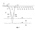
- FIG. 1 shows an example of a seismic survey vessel towing an example streamer according to the invention.
- FIG. 2 shows an example sensor group for the streamer shown in FIG. 1 .
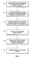
- FIG. 3 shows a flow chart of an example signal processing method using the streamer shown in FIG. 1 having sensor groups as shown in FIG. 2 .
- the system includes a seismic survey vessel 10 that moves along the surface of a body of water 11 such as a lake or the ocean.
- the seismic survey vessel 10 may include thereon equipment shown generally at 12 and referred to for convenience as a "recording system” that includes devices (none shown separately) for, among other functions, determining geodetic position of the vessel 10, for controlling actuation of one or more seismic energy sources 14 (explained further below), and for detecting and making a time indexed record of signals detected by seismic sensors disposed at spaced apart locations along one or more seismic sensor streamers 16.
- the recording system 12 may include a general purpose, programmable computer (not shown separately) for processing signals according to techniques to be further explained below.
- the streamer 16 may be towed by the seismic survey vessel 10 or by another vessel (not shown). Only one streamer 16 is shown in FIG. 1 for clarity of the illustration, however, it will be appreciated by those skilled in the art that typically a plurality of such streamers will be towed by the survey vessel 10 or by another vessel using certain towing equipment (not shown) to maintain the streamers in selected lateral positions with respect to each other and with respect to the center line of the towing vessel, e.g., the survey vessel 10.
- the one or more seismic energy sources 14 may be towed by the seismic survey vessel 10 or by another vessel (not shown).
- the one or more seismic energy sources 14 may be air guns, water guns, marine vibrators or arrays of such devices.
- the one or more seismic energy sources 14 are actuated at selected times and energy therefrom travels through the water 11 generally downwardly as shown at 20A and 21A until it reaches the water bottom 22 and one or more acoustic impedance boundaries 24 in the formations 23, 25 below the water bottom 22.
- Reflected seismic energy travels generally upwardly, shown at 20B and 21 B and is detected by seismic sensors (explained below with reference to FIG. 2 ) in the streamer 16.
- the seismic sensors may be disposed in a plurality of longitudinally spaced apart sensor groups 18.
- the recording system 12 may make recordings of the detected seismic signals generally indexed with respect to the actuation time of the one or more seismic energy sources 14.
- FIG. 2 shows an example of a seismic sensor group 18.
- the seismic sensor group 18 may include a plurality of individual pressure responsive or pressure time gradient responsive sensors 31 disposed at selected spacing (e.g., 0.5 meters) from each other to form a pressure responsive or pressure time gradient responsive sensor group 30 ("pressure sensor group").
- the individual sensors 31 ("pressure sensors") in the pressure sensor group 30 may be, for example, hydrophones that generate an electrical or optical signal in response to pressure or pressure time gradient.
- the signals from the individual pressure sensors 31 in the pressure sensor group 30 may be combined by electrically or optically connecting the signal output of individual pressure sensors 31 such that the pressure sensor group 30 effectively generates one pressure responsive signal that may be communicated to the recording system (12 in FIG. 1 ).
- the pressure responsive signal from the pressure sensor group 30 may be communicated in analog form or may be digitized at some location (not shown) along the streamer (16 in FIG. 1 ) using an analog to digital converter (not shown).
- the sensor group 18 may also include a plurality of spaced apart particle motion responsive sensors 33 that collectively form a particle motion responsive sensor group 32 ("motion sensor group").
- the particle motion responsive sensors 33 (“motion sensors”) may be geophones, velocity meters, accelerometers, or any other particle motion sensitive device known in the art.
- the motion sensors can be 1, 2 or 3 axis sensors.
- the motion sensors 33 may be arranged such that the longitudinal center of the motion sensor group 32 is approximately collocated with the longitudinal center of the pressure sensor group 30. In the present example there may be thirty or more motion sensors 33 in the motion sensor group 32.
- the motion sensors 33 may be three axis, microelectrical-mechanical systems ("MEMS") accelerometers.
- MEMS accelerometers One non-limiting example of a MEMS accelerometer that may be used in some examples is sold under model designation MTi by XSENS, Pantheon 6a, 7521 PR, ENSCHEDE, The Netherlands.
- MEMS accelerometer is sold under model designation ADXL50 by Analog Devices, Inc., 3 Technology Way, Norwood, Massachusetts 02062.
- Such accelerometers have detecting elements responsive to acceleration along each of three generally orthogonal directions.
- the motion sensors 33 may generate an electrical or optical signal related to the amount of acceleration applied along the sensitive axis of each detecting element.
- a possible benefit of using devices such as MEMS accelerometers as the motion sensors 33 is that their small size, weight and electrical power consumption makes possible the use of relatively large numbers of motion sensors 33 in the motion sensor group 31.
- the motion sensors 33 may be substantially evenly spaced apart from each other, including between adjacent sensor groups 18 along the streamer (16 in FIG. 1 ). Using relatively large numbers of motion sensors 33 in each motion sensor group 31, and the foregoing even spacing, may make possible certain types of signal processing that will be further explained below.
- the motion sensor group 32 may have associated therewith at a convenient position proximate the motion sensor group 32 a signal processing unit 36 such as a mixed signal digital signal processor.
- the signal processing unit 36 may include an internal multiplexer (not shown separately) that enables separate detection and processing of the signals from each detecting element (not shown separately) in each motion sensor 33 and analog to digital conversion circuitry (not shown separately).
- the signal processing unit 36 may also be programmed to calculate, from the signals from each detecting element in each motion sensor 33, either or both the vertical component of the motion wavefield at each motion sensor 33 and the total motion wavefield at each motion sensor 33.
- a streamer such as shown at 16 in FIG. 1 extends behind the towing vessel for several kilometers, and may include several hundred or more sensor groups (18 in FIG. 2 ) such as explained above.
- signals from the individual motion sensors may be processed to reduce the volume of signal data communicated to the recording system (12 in FIG. 1 ), while at the same time processing signals from the individual motion sensors (33 in FIG. 2 ) such that motion induced noise may be attenuated therefrom. Attenuation of the motion induced noise may enable determination of low frequency seismic signal components from the motion sensor signals.
- low frequency and high frequency as used in the present description are intended to mean frequencies below and above, respectively, a selected frequency threshold below which substantial motion induced noise is present in the signals from the motion sensors (33 in FIG. 2 ).
- frequency threshold is explained in the Vaage et al. '283 patent referred to in the Background section herein, and is typically in the range of 20 Hz to 30 Hz.
- FIG. 3 shows a flow chart of an example signal detection and processing technique according to the invention.
- the signal processing unit (36 in FIG. 2 ) may digitize and sample the signal output of each sensing element in each motion sensor (33 in FIG. 2 ) at a sample rate related to an uppermost frequency in a seismic frequency range of interest. For example, such sample rate may be 200 to 400 Hz for an upper seismic frequency limit of 100 Hz to 200 Hz.
- the digitally sampled motion sensor signals may be separated into low frequency component signals and high frequency component signals, using a selected frequency threshold as explained above.
- the group motion sensor signal may be the vertical component of the motion wavefield, the summed vertical and crossline component, or may be the total motion wavefield, as explained above. Calculation of either of the foregoing motion wavefields may be performed in the signal processing unit (36 in FIG. 2 ).
- the group motion signals thus determined may be communicated to the recording system (12 in FIG. 1 ) at the selected digital sampling rate.
- the low frequency component signals from each individual motion sensor may be communicated to the recording system (12 in FIG. 1 ).
- such communication may be at a lower sample rate related to the threshold frequency. For example, if the threshold frequency is 20 Hz, the low frequency components of the individual motion sensor signals may be communicated to the recording system (12 in FIG. 1 ) at a sample rate of 40 Hz.
- Such lower frequency communication may preserve streamer telemetry capacity for other signals, e.g., the high frequency component signals.
- the foregoing signals communicated to the recording system (12 in FIG. 1 ) may be further processed as explained below on the computer in the recording system (12 in FIG. 1 ), or on another programmable computer (that may be located elsewhere) using as signal input the signal recordings made in the recording unit (12 in FIG. 1 ).
- the low frequency component of the individual motion sensor signals may be velocity filtered.
- velocity filtering may be, for example, frequency-wavenumber ( f - k ) filtering, or slant stack (tau-p) filtering.
- a velocity threshold for the velocity filtering may be selected to exclude from the signals any components having slower velocity than the speed of sound in water (about 1500 meters per second). It is expected that motion induced noise has slower velocity than the speed of sound in water.
- Velocity filtering is made practical by the use of the relatively large number of motion sensors (33 in FIG. 2 ) and their substantially even spacing therebetween.
- the velocity filtered low frequency component signals from each motion sensor group may then be summed.
- the summed low frequency component signals from each group may then be summed with the high frequency component signals from the same motion sensor group to produce a full bandwidth motion sensor signal for each motion sensor group.
- the full bandwidth motion sensor signals may be relatively free of motion induced noise.
- the full bandwidth motion signals from each motion sensor group may be combined with the pressure sensor group signals from each corresponding pressure sensor group in any manner known in the art for combined motion and pressure signal processing. See, for example, U.S. Patent No. 6,021,092 issued to Paffenholz et al. , or U.S. Patent No. 5,163,028 issued to Barr et al . Such combination may produce, for example, seismic signals in which effects of seismic energy reflection from the water surface have been attenuated. Such seismic signals may be referred to as "deghosted" seismic signals.
- telemetry capacity in the streamer (16 in FIG. 1 ) is not limited, it is possible to send the full bandwidth signal from each individual motion sensor (33 in FIG. 2 ) and each individual pressure sensor (31 in FIG. 2 ) to the recording unit (12 in FIG. 1 ) for recording. Processing the signals as explained with reference to FIG. 3 may be performed on the computer in the recording unit or on another computer. In the present example, however, the motion sensor group signal may be generated by separating the full bandwidth motion sensor signals into high frequency and low frequency components, as previously explained, at a selected frequency related to a frequency limit of substantial motion induced noise. The high frequency component signals from the motion sensors in each group (32 in FIG.
- the low frequency components may be velocity filtered as explained above, and the remainder of the processing may be performed as explained above with reference to FIG. 3 .
- the pressure signals from individual pressure sensors may be combined to generate a pressure sensor group signal for each pressure sensor group (30 in FIG. 2 ) in the computer.
- Methods and systems according to the invention may provide improved seismic data because the effects of noise on the low frequency portion of particle motion sensor signals is substantially reduced.
Landscapes
- Engineering & Computer Science (AREA)
- Remote Sensing (AREA)
- Physics & Mathematics (AREA)
- Life Sciences & Earth Sciences (AREA)
- Acoustics & Sound (AREA)
- Environmental & Geological Engineering (AREA)
- Geology (AREA)
- General Life Sciences & Earth Sciences (AREA)
- General Physics & Mathematics (AREA)
- Geophysics (AREA)
- Geophysics And Detection Of Objects (AREA)
Abstract
Description
- The invention relates generally to the field of marine seismic survey systems. More specifically, the invention relates to structures for sensor groups in marine seismic streamers having particle motion sensors and pressure sensors.
- Marine seismic survey systems known in the art include sensor cables called "streamers" towed in a body of water to acquire seismic signals resulting from actuation at selected times of one or more seismic energy sources in the water. Streamers include a plurality of seismic sensors disposed at spaced apart locations along the streamer. Typically, the sensors are arranged in a plurality of spaced apart groups or "arrays", wherein in each such group or array a selected number of sensors are disposed at relatively close spacing (e.g., 0.7 meters), and the signals from all the sensors in the group are combined in some manner to generate the equivalent of a single sensor signal. The sensor groups may be separated from each other by a relatively longer spacing (e.g., 12.5 meters) to provide the equivalent of signals from a plurality of individual sensors disposed at spaced apart locations along the streamer. Sensor grouping and signal combination as explained above is used to reduce certain types of noise in the signals detected by the seismic sensors.
- One type of seismic streamer known in the art called a "dual sensor" streamer includes both particle motion responsive sensors (e.g., geophones) and pressure or pressure time gradient responsive sensors (e.g., hydrophones) disposed in substantially collocated groups. One example of such type of streamer is disclosed in
U.S. Patent No. 7,239,577 issued to Tenghamn et al . and commonly owned with the present invention. The particular uses for such dual sensor streamers are well described in the foregoing patent. - It is known in the art that in seismic streamers having particle motion sensors, including dual sensor streamers, the particle motion sensors are susceptible to noise generated by the movement of the streamers in the water. One technique for processing dual sensor seismic streamer signals that takes account of such noise is described in
U.S. Patent No. 7,359,283 issued to Vaage et al . and commonly owned with the present invention. The method described in the foregoing patent includes synthesizing low frequency (e.g., below about 20 Hz) particle motion signals using signals from the pressure responsive sensors, and adding the synthesized low frequency components to measurements made by the particle motion sensors above the synthesized signal frequency limit. Particle motion signals measured by the particle motion sensors below the synthesis frequency limit are effectively not used in such method. As a result, potentially valuable low frequency particle motion information may be unobtainable. - One way to reduce noise in the lower part of the seismic frequency band in signals detected by the motion sensors is to use single sensor measurements. To do this it is necessary to have relatively densely spaced sensors that preferably are equally spaced over the group length. Such sensor arrangements ha ve not been practicable due to limitations of power consumption along the streamer and limitations in handling large volumes of sensor data.
- There continues to be a need for improved structures and signal processing techniques for seismic streamers including particle motion sensors that can attenuate the effects of motion induced noise in the particle motion sensor signals.
- A method for marine seismic surveying according to one aspect of the invention includes towing a streamer in a body of water. The streamer includes a plurality of spaced apart sensor groups, each including a plurality of longitudinally spaced apart pressure sensors and particle motion responsive sensors. Signals are detected at each of the sensors in response to actuation of a seismic energy source. Components of the sampled motion signals in each group above a selected frequency are combined to generate respective group motion signals. Components of the motion responsive signals below the selected frequency are velocity filtered. The velocity filtered signals are combined with the group motion signals to generate full bandwidth motion responsive signals corresponding to each sensor group.
- Other aspects and advantages of the invention will be apparent from the following description and the appended claims.
-
FIG. 1 shows an example of a seismic survey vessel towing an example streamer according to the invention. -
FIG. 2 shows an example sensor group for the streamer shown inFIG. 1 . -
FIG. 3 shows a flow chart of an example signal processing method using the streamer shown inFIG. 1 having sensor groups as shown inFIG. 2 . - An example seismic acquisition system is shown schematically in
FIG. 1 . The system includes aseismic survey vessel 10 that moves along the surface of a body ofwater 11 such as a lake or the ocean. Theseismic survey vessel 10 may include thereon equipment shown generally at 12 and referred to for convenience as a "recording system" that includes devices (none shown separately) for, among other functions, determining geodetic position of thevessel 10, for controlling actuation of one or more seismic energy sources 14 (explained further below), and for detecting and making a time indexed record of signals detected by seismic sensors disposed at spaced apart locations along one or moreseismic sensor streamers 16. Therecording system 12 may include a general purpose, programmable computer (not shown separately) for processing signals according to techniques to be further explained below. - The
streamer 16 may be towed by theseismic survey vessel 10 or by another vessel (not shown). Only onestreamer 16 is shown inFIG. 1 for clarity of the illustration, however, it will be appreciated by those skilled in the art that typically a plurality of such streamers will be towed by thesurvey vessel 10 or by another vessel using certain towing equipment (not shown) to maintain the streamers in selected lateral positions with respect to each other and with respect to the center line of the towing vessel, e.g., thesurvey vessel 10. - The one or more
seismic energy sources 14 may be towed by theseismic survey vessel 10 or by another vessel (not shown). The one or moreseismic energy sources 14 may be air guns, water guns, marine vibrators or arrays of such devices. The one or moreseismic energy sources 14 are actuated at selected times and energy therefrom travels through thewater 11 generally downwardly as shown at 20A and 21A until it reaches thewater bottom 22 and one or moreacoustic impedance boundaries 24 in theformations water bottom 22. Reflected seismic energy travels generally upwardly, shown at 20B and 21 B and is detected by seismic sensors (explained below with reference toFIG. 2 ) in thestreamer 16. In the present example, the seismic sensors may be disposed in a plurality of longitudinally spaced apartsensor groups 18. Therecording system 12 may make recordings of the detected seismic signals generally indexed with respect to the actuation time of the one or moreseismic energy sources 14. -
FIG. 2 shows an example of aseismic sensor group 18. Theseismic sensor group 18 may include a plurality of individual pressure responsive or pressure time gradientresponsive sensors 31 disposed at selected spacing (e.g., 0.5 meters) from each other to form a pressure responsive or pressure time gradient responsive sensor group 30 ("pressure sensor group"). The individual sensors 31 ("pressure sensors") in thepressure sensor group 30 may be, for example, hydrophones that generate an electrical or optical signal in response to pressure or pressure time gradient. In some examples, the signals from theindividual pressure sensors 31 in thepressure sensor group 30 may be combined by electrically or optically connecting the signal output ofindividual pressure sensors 31 such that thepressure sensor group 30 effectively generates one pressure responsive signal that may be communicated to the recording system (12 inFIG. 1 ). The pressure responsive signal from thepressure sensor group 30 may be communicated in analog form or may be digitized at some location (not shown) along the streamer (16 inFIG. 1 ) using an analog to digital converter (not shown). In some examples, there may be sixteenpressure sensors 31 in eachpressure sensor group 30, although the exact number of pressure sensors in each pressure sensor group is not a limit on the scope of the present invention. - The
sensor group 18 may also include a plurality of spaced apart particle motionresponsive sensors 33 that collectively form a particle motion responsive sensor group 32 ("motion sensor group"). The particle motion responsive sensors 33 ("motion sensors") may be geophones, velocity meters, accelerometers, or any other particle motion sensitive device known in the art. The motion sensors can be 1, 2 or 3 axis sensors. Themotion sensors 33 may be arranged such that the longitudinal center of themotion sensor group 32 is approximately collocated with the longitudinal center of thepressure sensor group 30. In the present example there may be thirty ormore motion sensors 33 in themotion sensor group 32. - In the present example, the
motion sensors 33 may be three axis, microelectrical-mechanical systems ("MEMS") accelerometers. One non-limiting example of a MEMS accelerometer that may be used in some examples is sold under model designation MTi by XSENS, Pantheon 6a, 7521 PR, ENSCHEDE, The Netherlands. Another non-limiting example of MEMS accelerometer is sold under model designation ADXL50 by Analog Devices, Inc., 3 Technology Way, Norwood, Massachusetts 02062. Such accelerometers have detecting elements responsive to acceleration along each of three generally orthogonal directions. Themotion sensors 33 may generate an electrical or optical signal related to the amount of acceleration applied along the sensitive axis of each detecting element. A possible benefit of using devices such as MEMS accelerometers as themotion sensors 33 is that their small size, weight and electrical power consumption makes possible the use of relatively large numbers ofmotion sensors 33 in themotion sensor group 31. In the present example, themotion sensors 33 may be substantially evenly spaced apart from each other, including betweenadjacent sensor groups 18 along the streamer (16 inFIG. 1 ). Using relatively large numbers ofmotion sensors 33 in eachmotion sensor group 31, and the foregoing even spacing, may make possible certain types of signal processing that will be further explained below. - The
motion sensor group 32 may have associated therewith at a convenient position proximate the motion sensor group 32 asignal processing unit 36 such as a mixed signal digital signal processor. Thesignal processing unit 36 may include an internal multiplexer (not shown separately) that enables separate detection and processing of the signals from each detecting element (not shown separately) in eachmotion sensor 33 and analog to digital conversion circuitry (not shown separately). Thesignal processing unit 36 may also be programmed to calculate, from the signals from each detecting element in eachmotion sensor 33, either or both the vertical component of the motion wavefield at eachmotion sensor 33 and the total motion wavefield at eachmotion sensor 33. It is possible to calculate the vertical component of the motion wavefield using the described accelerometers because there are two or three orthogonal detecting elements, thus making possible determination of the component of acceleration resulting from Earth's gravity that is detected by each detecting element. The gravity orientation of eachmotion sensor 33 may thus be determined, enabling resolution of the vertical component of the motion wavefield. Signals output from thesignal processing unit 36 may be conducted to the recording system (12 inFIG. 1 ) for processing as will be further explained. - Typically, a streamer such as shown at 16 in
FIG. 1 extends behind the towing vessel for several kilometers, and may include several hundred or more sensor groups (18 inFIG. 2 ) such as explained above. Because of the resulting very large number of individual seismic sensors present in the typical streamer, in an example signal processing technique according to the invention, signals from the individual motion sensors (33 inFIG. 2 ) may be processed to reduce the volume of signal data communicated to the recording system (12 inFIG. 1 ), while at the same time processing signals from the individual motion sensors (33 inFIG. 2 ) such that motion induced noise may be attenuated therefrom. Attenuation of the motion induced noise may enable determination of low frequency seismic signal components from the motion sensor signals. The terms "low frequency" and "high frequency" as used in the present description are intended to mean frequencies below and above, respectively, a selected frequency threshold below which substantial motion induced noise is present in the signals from the motion sensors (33 inFIG. 2 ). Such frequency threshold is explained in the Vaage et al. '283 patent referred to in the Background section herein, and is typically in the range of 20 Hz to 30 Hz. -
FIG. 3 shows a flow chart of an example signal detection and processing technique according to the invention. At 40, the signal processing unit (36 inFIG. 2 ) may digitize and sample the signal output of each sensing element in each motion sensor (33 inFIG. 2 ) at a sample rate related to an uppermost frequency in a seismic frequency range of interest. For example, such sample rate may be 200 to 400 Hz for an upper seismic frequency limit of 100 Hz to 200 Hz. At 42, the digitally sampled motion sensor signals may be separated into low frequency component signals and high frequency component signals, using a selected frequency threshold as explained above. The high frequency component signals from the all the motion sensors (33 inFIG. 2 ) in each motion sensor group (32 inFIG. 2 ) may be combined, added or summed to generate a single group motion sensor signal. The group motion sensor signal may be the vertical component of the motion wavefield, the summed vertical and crossline component, or may be the total motion wavefield, as explained above. Calculation of either of the foregoing motion wavefields may be performed in the signal processing unit (36 inFIG. 2 ). The group motion signals thus determined may be communicated to the recording system (12 inFIG. 1 ) at the selected digital sampling rate. - At 44, the low frequency component signals from each individual motion sensor (33 in
FIG. 2 ) may be communicated to the recording system (12 inFIG. 1 ). In one example, such communication may be at a lower sample rate related to the threshold frequency. For example, if the threshold frequency is 20 Hz, the low frequency components of the individual motion sensor signals may be communicated to the recording system (12 inFIG. 1 ) at a sample rate of 40 Hz. Such lower frequency communication may preserve streamer telemetry capacity for other signals, e.g., the high frequency component signals. - The foregoing signals communicated to the recording system (12 in
FIG. 1 ) may be further processed as explained below on the computer in the recording system (12 inFIG. 1 ), or on another programmable computer (that may be located elsewhere) using as signal input the signal recordings made in the recording unit (12 inFIG. 1 ). - At 46, the low frequency component of the individual motion sensor signals may be velocity filtered. Such velocity filtering may be, for example, frequency-wavenumber (f-k) filtering, or slant stack (tau-p) filtering. A velocity threshold for the velocity filtering may be selected to exclude from the signals any components having slower velocity than the speed of sound in water (about 1500 meters per second). It is expected that motion induced noise has slower velocity than the speed of sound in water. Velocity filtering is made practical by the use of the relatively large number of motion sensors (33 in
FIG. 2 ) and their substantially even spacing therebetween. - At 48, the velocity filtered low frequency component signals from each motion sensor group (32 in
FIG. 1 ) may then be summed. The summed low frequency component signals from each group may then be summed with the high frequency component signals from the same motion sensor group to produce a full bandwidth motion sensor signal for each motion sensor group. The full bandwidth motion sensor signals may be relatively free of motion induced noise. - At 50, the full bandwidth motion signals from each motion sensor group may be combined with the pressure sensor group signals from each corresponding pressure sensor group in any manner known in the art for combined motion and pressure signal processing. See, for example,
U.S. Patent No. 6,021,092 issued to Paffenholz et al. , orU.S. Patent No. 5,163,028 issued to Barr et al . Such combination may produce, for example, seismic signals in which effects of seismic energy reflection from the water surface have been attenuated. Such seismic signals may be referred to as "deghosted" seismic signals. - In another example, wherein telemetry capacity in the streamer (16 in
FIG. 1 ) is not limited, it is possible to send the full bandwidth signal from each individual motion sensor (33 inFIG. 2 ) and each individual pressure sensor (31 inFIG. 2 ) to the recording unit (12 inFIG. 1 ) for recording. Processing the signals as explained with reference toFIG. 3 may be performed on the computer in the recording unit or on another computer. In the present example, however, the motion sensor group signal may be generated by separating the full bandwidth motion sensor signals into high frequency and low frequency components, as previously explained, at a selected frequency related to a frequency limit of substantial motion induced noise. The high frequency component signals from the motion sensors in each group (32 inFIG. 2 ) may be combined or added in the computer, rather than by the signal processing unit (36 inFIG. 2 ) as explained with reference toFIG. 2 . The low frequency components may be velocity filtered as explained above, and the remainder of the processing may be performed as explained above with reference toFIG. 3 . Similarly, the pressure signals from individual pressure sensors may be combined to generate a pressure sensor group signal for each pressure sensor group (30 inFIG. 2 ) in the computer. - Methods and systems according to the invention may provide improved seismic data because the effects of noise on the low frequency portion of particle motion sensor signals is substantially reduced.
- While the invention has been described with respect to a limited number of embodiments, those skilled in the art, having benefit of this disclosure, will appreciate that other embodiments can be devised which do not depart from the scope of the invention as disclosed herein. Accordingly, the scope of the invention should be limited only by the attached claims.
Claims (10)
- A method for marine seismic surveying, comprising:towing at least one seismic streamer in a body of water, the streamer including a plurality of spaced apart sensor groups, each sensor group including a plurality of longitudinally spaced apart particle motion responsive sensors;detecting signals at each of the particle motion responsive signals in response to actuation of a seismic energy source;summing components of the particle motion responsive signals in each group above a selected frequency to generate respective group motion signals;velocity filtering components of the motion responsive signals below the selected frequency; andcombining the velocity filtered signals with the group motion signals to generate full bandwidth motion responsive signals corresponding to each sensor group.
- The method of claim 1 wherein the velocity filtering comprises excluding signal components below a velocity of sound in water.
- The method of claim 1 wherein the velocity filtering comprises frequency-wavenumber filtering.
- The method of claim 1 wherein the velocity filtering comprises slant stack filtering.
- The method of claim 1 wherein the components of the motion signals below the selected frequency are communicated to the recording system at a sample rate related to the selected frequency, the sample rate lower than a digital sample rate related to an upper limit of a seismic frequency range of interest.
- The method of claim 1 wherein the selected frequency is related to a frequency of towing motion induced noise in the motion responsive sensor signals.
- The method of claim 6 wherein the selected frequency is about 20 Hz.
- The method of claim 1 wherein the at least one streamer comprises a plurality of pressure responsive sensor groups each substantially collocated with each particle motion responsive sensor group, and wherein the method further comprises:detecting pressure responsive signals in response to actuation of the seismic energy source; andcombining the pressure responsive signals with the full bandwidth motion responsive signals to generate deghosted seismic signals.
- The method of claim 1 wherein the detected motion responsive signals are digitally sampled in the streamer at a rate corresponding to a maximum seismic frequency of interest, and wherein the motion responsive signals below the selected frequency are communicated to a recording system at a sample rate related to the selected frequency and lower than the digital sampling rate.
- The method of claim 1 wherein the motion responsive signal components above the selected frequency are combined in the streamer to generate the respective group motion responsive signals, and the respective group motion responsive signals are communicated from the streamer to a recording system.
Applications Claiming Priority (1)
| Application Number | Priority Date | Filing Date | Title |
|---|---|---|---|
| US12/583,861 US9285493B2 (en) | 2009-08-27 | 2009-08-27 | Sensor grouping for dual sensor marine seismic streamer and method for seismic surveying |
Publications (3)
| Publication Number | Publication Date |
|---|---|
| EP2293116A2 true EP2293116A2 (en) | 2011-03-09 |
| EP2293116A3 EP2293116A3 (en) | 2012-06-20 |
| EP2293116B1 EP2293116B1 (en) | 2014-07-30 |
Family
ID=43333266
Family Applications (1)
| Application Number | Title | Priority Date | Filing Date |
|---|---|---|---|
| EP10174057.9A Active EP2293116B1 (en) | 2009-08-27 | 2010-08-25 | Sensor grouping for dual sensor marine seismic streamer and method for seismic surveying |
Country Status (10)
| Country | Link |
|---|---|
| US (1) | US9285493B2 (en) |
| EP (1) | EP2293116B1 (en) |
| CN (1) | CN102004265B (en) |
| AU (1) | AU2010203087B2 (en) |
| BR (1) | BRPI1003021B1 (en) |
| CA (1) | CA2713631C (en) |
| DK (1) | DK2293116T3 (en) |
| EA (1) | EA018827B1 (en) |
| EG (1) | EG25593A (en) |
| MX (1) | MX2010009369A (en) |
Cited By (6)
| Publication number | Priority date | Publication date | Assignee | Title |
|---|---|---|---|---|
| FR2979021A1 (en) * | 2011-08-09 | 2013-02-15 | Pgs Geophysical As | DIGITAL SENSOR MARINE FLUTE AND APPLICATIONS THEREOF |
| WO2015026997A1 (en) * | 2013-08-21 | 2015-02-26 | Westerngeco Llc | Computing a gradient based on differences of plural pairs of particle motion sensors |
| CN104570058A (en) * | 2014-12-26 | 2015-04-29 | 深圳市微纳集成电路与系统应用研究院 | Impending earthquake monitoring probe structure based on multiple sensors |
| EP3144928A1 (en) * | 2015-09-15 | 2017-03-22 | Harman Becker Automotive Systems GmbH | Noise and vibration sensing |
| US10048395B2 (en) | 2013-02-01 | 2018-08-14 | Westerngeco L.L.C. | Computing a gradient based on differences of plural pairs of particle motion sensors |
| US10408954B2 (en) | 2014-01-17 | 2019-09-10 | Westerngeco L.L.C. | Seismic sensor coupling |
Families Citing this family (10)
| Publication number | Priority date | Publication date | Assignee | Title |
|---|---|---|---|---|
| US9256001B2 (en) * | 2010-12-28 | 2016-02-09 | Solid Seismic, Llc | Bandwidth enhancing liquid coupled piezoelectric sensor apparatus and method of use thereof |
| US8902936B2 (en) * | 2011-12-22 | 2014-12-02 | Cory J. Stephanson | Sensor event assessor input/output controller |
| US10165228B2 (en) | 2011-12-22 | 2018-12-25 | Mis Security, Llc | Sensor event assessor training and integration |
| US10338250B2 (en) | 2013-03-14 | 2019-07-02 | Pgs Geophysical As | Method of removing incoherent noise |
| US9846247B2 (en) * | 2013-03-15 | 2017-12-19 | Pgs Geophysical As | Methods and systems for interpolation of multi-component seismic data collected in a marine environment |
| US11092710B2 (en) | 2013-06-27 | 2021-08-17 | Pgs Geophysical As | Inversion techniques using streamers at different depths |
| US10459100B2 (en) | 2013-06-27 | 2019-10-29 | Pgs Geophysical As | Survey techniques using streamers at different depths |
| US10591622B2 (en) | 2013-10-30 | 2020-03-17 | Pgs Geophysical As | Reconfigurable seismic sensor cable |
| WO2017106220A1 (en) * | 2015-12-16 | 2017-06-22 | Downunder Geosolutions (America) Llc | Method for removing interference caused by time overlapping seismic recordings and seismic survey acquisition method associated therewith |
| US11079506B2 (en) | 2016-12-16 | 2021-08-03 | Pgs Geophysical As | Multicomponent streamer |
Citations (4)
| Publication number | Priority date | Publication date | Assignee | Title |
|---|---|---|---|---|
| US5163028A (en) | 1991-09-27 | 1992-11-10 | Halliburton Geophysical Services, Inc. | Method for correcting impulse response differences of hydrophones and geophones as well as geophone coupling to the water-bottom in dual-sensor, bottom-cable seismic operations |
| US6021092A (en) | 1997-06-09 | 2000-02-01 | Western Atlas International, Inc. | Method for deriving surface consistent reflectivity map from dual sensor seismic data |
| US7239577B2 (en) | 2002-08-30 | 2007-07-03 | Pgs Americas, Inc. | Apparatus and methods for multicomponent marine geophysical data gathering |
| US7359283B2 (en) | 2004-03-03 | 2008-04-15 | Pgs Americas, Inc. | System for combining signals of pressure sensors and particle motion sensors in marine seismic streamers |
Family Cites Families (12)
| Publication number | Priority date | Publication date | Assignee | Title |
|---|---|---|---|---|
| GB2309082B (en) * | 1996-01-09 | 1999-12-01 | Geco As | Noise filtering method |
| GB9906456D0 (en) * | 1999-03-22 | 1999-05-12 | Geco Prakla Uk Ltd | Method and system for reducing effects of sea surface ghost contamination in seismic data |
| GB2379741B (en) | 2001-09-18 | 2003-11-19 | Westerngeco Ltd | Method for reducing the effect of Sea-surface ghost reflections |
| US6691039B1 (en) * | 2002-08-30 | 2004-02-10 | John M. Robinson | Removal of noise from seismic data using improved radon transformations |
| RU28923U1 (en) | 2003-01-21 | 2003-04-20 | Федеральное государственное унитарное предприятие "Научно-исследовательский и проектный институт геофизических методов разведки океана" "НИПИокеангеофизика" | Multicomponent receiver for seismic exploration on the shelf and in transitional zones of land-sea |
| US8824239B2 (en) | 2004-03-17 | 2014-09-02 | Westerngeco L.L.C. | Marine seismic survey method and system |
| US7835223B2 (en) * | 2006-12-21 | 2010-11-16 | Westerngeco L.L.C. | Removing noise from seismic data obtained from towed seismic sensors |
| US20080151689A1 (en) * | 2006-12-21 | 2008-06-26 | Nicolas Goujon | Removing vibration noise from seismic data obtained from towed seismic sensors |
| US9001618B2 (en) * | 2007-12-05 | 2015-04-07 | Pgs Geophysical As | Method of attenuating noise in marine seismic streamers utilizing varied sensor spacing and position-dependent band-pass filters |
| GB2458642A (en) * | 2008-03-25 | 2009-09-30 | Geco Technology Bv | Noise attenuation of seismic data |
| US20100172208A1 (en) * | 2009-01-07 | 2010-07-08 | Ashok Belani | System and technique for local in-sea processing of particle motion data |
| US20100211320A1 (en) * | 2009-02-13 | 2010-08-19 | Massimiliano Vassallo | Reconstructing a seismic wavefield |
-
2009
- 2009-08-27 US US12/583,861 patent/US9285493B2/en active Active
-
2010
- 2010-07-20 AU AU2010203087A patent/AU2010203087B2/en active Active
- 2010-08-04 EG EG2010081311A patent/EG25593A/en active
- 2010-08-20 CA CA2713631A patent/CA2713631C/en active Active
- 2010-08-24 EA EA201001200A patent/EA018827B1/en not_active IP Right Cessation
- 2010-08-25 MX MX2010009369A patent/MX2010009369A/en active IP Right Grant
- 2010-08-25 DK DK10174057.9T patent/DK2293116T3/en active
- 2010-08-25 EP EP10174057.9A patent/EP2293116B1/en active Active
- 2010-08-26 BR BRPI1003021A patent/BRPI1003021B1/en active IP Right Grant
- 2010-08-27 CN CN201010267429.9A patent/CN102004265B/en not_active Expired - Fee Related
Patent Citations (4)
| Publication number | Priority date | Publication date | Assignee | Title |
|---|---|---|---|---|
| US5163028A (en) | 1991-09-27 | 1992-11-10 | Halliburton Geophysical Services, Inc. | Method for correcting impulse response differences of hydrophones and geophones as well as geophone coupling to the water-bottom in dual-sensor, bottom-cable seismic operations |
| US6021092A (en) | 1997-06-09 | 2000-02-01 | Western Atlas International, Inc. | Method for deriving surface consistent reflectivity map from dual sensor seismic data |
| US7239577B2 (en) | 2002-08-30 | 2007-07-03 | Pgs Americas, Inc. | Apparatus and methods for multicomponent marine geophysical data gathering |
| US7359283B2 (en) | 2004-03-03 | 2008-04-15 | Pgs Americas, Inc. | System for combining signals of pressure sensors and particle motion sensors in marine seismic streamers |
Cited By (7)
| Publication number | Priority date | Publication date | Assignee | Title |
|---|---|---|---|---|
| FR2979021A1 (en) * | 2011-08-09 | 2013-02-15 | Pgs Geophysical As | DIGITAL SENSOR MARINE FLUTE AND APPLICATIONS THEREOF |
| US10048395B2 (en) | 2013-02-01 | 2018-08-14 | Westerngeco L.L.C. | Computing a gradient based on differences of plural pairs of particle motion sensors |
| WO2015026997A1 (en) * | 2013-08-21 | 2015-02-26 | Westerngeco Llc | Computing a gradient based on differences of plural pairs of particle motion sensors |
| US10408954B2 (en) | 2014-01-17 | 2019-09-10 | Westerngeco L.L.C. | Seismic sensor coupling |
| CN104570058A (en) * | 2014-12-26 | 2015-04-29 | 深圳市微纳集成电路与系统应用研究院 | Impending earthquake monitoring probe structure based on multiple sensors |
| EP3144928A1 (en) * | 2015-09-15 | 2017-03-22 | Harman Becker Automotive Systems GmbH | Noise and vibration sensing |
| US10096314B2 (en) | 2015-09-15 | 2018-10-09 | Harman Becker Automotive Systems Gmbh | Noise and vibration sensing |
Also Published As
| Publication number | Publication date |
|---|---|
| AU2010203087A1 (en) | 2011-03-17 |
| BRPI1003021A2 (en) | 2012-04-24 |
| CN102004265A (en) | 2011-04-06 |
| AU2010203087B2 (en) | 2015-11-26 |
| EA201001200A1 (en) | 2011-02-28 |
| EA018827B1 (en) | 2013-11-29 |
| US9285493B2 (en) | 2016-03-15 |
| CA2713631C (en) | 2016-10-11 |
| MX2010009369A (en) | 2011-02-28 |
| EP2293116A3 (en) | 2012-06-20 |
| EG25593A (en) | 2012-03-14 |
| CA2713631A1 (en) | 2011-02-27 |
| DK2293116T3 (en) | 2014-09-08 |
| BRPI1003021B1 (en) | 2020-01-14 |
| US20110051551A1 (en) | 2011-03-03 |
| CN102004265B (en) | 2016-08-17 |
| EP2293116B1 (en) | 2014-07-30 |
Similar Documents
| Publication | Publication Date | Title |
|---|---|---|
| EP2293116B1 (en) | Sensor grouping for dual sensor marine seismic streamer and method for seismic surveying | |
| EP1709464B1 (en) | Marine seismic acquisition system | |
| EP2060934B1 (en) | Array grouping of seismic sensors in a marine streamer for optimum noise attenuation | |
| US10330806B2 (en) | Dual axis geophones for pressure/velocity sensing streamers forming a triple component streamer | |
| AU2008249205B2 (en) | Method and apparatus for marine seismic data acquisition | |
| AU2008307383B2 (en) | Seismic streamer platform | |
| AU2008284172B2 (en) | Removing vibration noise from multicomponent streamer measurements | |
| EA016522B1 (en) | Method for estimating formation quality | |
| AU2016276319A1 (en) | Seismic sensor cable |
Legal Events
| Date | Code | Title | Description |
|---|---|---|---|
| PUAI | Public reference made under article 153(3) epc to a published international application that has entered the european phase |
Free format text: ORIGINAL CODE: 0009012 |
|
| AK | Designated contracting states |
Kind code of ref document: A2 Designated state(s): AL AT BE BG CH CY CZ DE DK EE ES FI FR GB GR HR HU IE IS IT LI LT LU LV MC MK MT NL NO PL PT RO SE SI SK SM TR |
|
| AX | Request for extension of the european patent |
Extension state: BA ME RS |
|
| PUAL | Search report despatched |
Free format text: ORIGINAL CODE: 0009013 |
|
| AK | Designated contracting states |
Kind code of ref document: A3 Designated state(s): AL AT BE BG CH CY CZ DE DK EE ES FI FR GB GR HR HU IE IS IT LI LT LU LV MC MK MT NL NO PL PT RO SE SI SK SM TR |
|
| AX | Request for extension of the european patent |
Extension state: BA ME RS |
|
| RIC1 | Information provided on ipc code assigned before grant |
Ipc: G01V 1/20 20060101AFI20120515BHEP Ipc: G01V 1/38 20060101ALI20120515BHEP |
|
| 17P | Request for examination filed |
Effective date: 20120724 |
|
| GRAP | Despatch of communication of intention to grant a patent |
Free format text: ORIGINAL CODE: EPIDOSNIGR1 |
|
| INTG | Intention to grant announced |
Effective date: 20131108 |
|
| RAP1 | Party data changed (applicant data changed or rights of an application transferred) |
Owner name: PGS GEOPHYSICAL AS |
|
| GRAP | Despatch of communication of intention to grant a patent |
Free format text: ORIGINAL CODE: EPIDOSNIGR1 |
|
| GRAS | Grant fee paid |
Free format text: ORIGINAL CODE: EPIDOSNIGR3 |
|
| GRAA | (expected) grant |
Free format text: ORIGINAL CODE: 0009210 |
|
| INTG | Intention to grant announced |
Effective date: 20140616 |
|
| AK | Designated contracting states |
Kind code of ref document: B1 Designated state(s): AL AT BE BG CH CY CZ DE DK EE ES FI FR GB GR HR HU IE IS IT LI LT LU LV MC MK MT NL NO PL PT RO SE SI SK SM TR |
|
| REG | Reference to a national code |
Ref country code: GB Ref legal event code: FG4D |
|
| REG | Reference to a national code |
Ref country code: CH Ref legal event code: EP |
|
| REG | Reference to a national code |
Ref country code: AT Ref legal event code: REF Ref document number: 680229 Country of ref document: AT Kind code of ref document: T Effective date: 20140815 |
|
| REG | Reference to a national code |
Ref country code: IE Ref legal event code: FG4D |
|
| REG | Reference to a national code |
Ref country code: DK Ref legal event code: T3 Effective date: 20140902 |
|
| REG | Reference to a national code |
Ref country code: DE Ref legal event code: R096 Ref document number: 602010017850 Country of ref document: DE Effective date: 20140911 |
|
| REG | Reference to a national code |
Ref country code: NL Ref legal event code: T3 |
|
| REG | Reference to a national code |
Ref country code: NO Ref legal event code: T2 Effective date: 20140730 |
|
| REG | Reference to a national code |
Ref country code: AT Ref legal event code: MK05 Ref document number: 680229 Country of ref document: AT Kind code of ref document: T Effective date: 20140730 |
|
| REG | Reference to a national code |
Ref country code: LT Ref legal event code: MG4D |
|
| PG25 | Lapsed in a contracting state [announced via postgrant information from national office to epo] |
Ref country code: BG Free format text: LAPSE BECAUSE OF FAILURE TO SUBMIT A TRANSLATION OF THE DESCRIPTION OR TO PAY THE FEE WITHIN THE PRESCRIBED TIME-LIMIT Effective date: 20141030 Ref country code: ES Free format text: LAPSE BECAUSE OF FAILURE TO SUBMIT A TRANSLATION OF THE DESCRIPTION OR TO PAY THE FEE WITHIN THE PRESCRIBED TIME-LIMIT Effective date: 20140730 Ref country code: PT Free format text: LAPSE BECAUSE OF FAILURE TO SUBMIT A TRANSLATION OF THE DESCRIPTION OR TO PAY THE FEE WITHIN THE PRESCRIBED TIME-LIMIT Effective date: 20141202 Ref country code: LT Free format text: LAPSE BECAUSE OF FAILURE TO SUBMIT A TRANSLATION OF THE DESCRIPTION OR TO PAY THE FEE WITHIN THE PRESCRIBED TIME-LIMIT Effective date: 20140730 Ref country code: SE Free format text: LAPSE BECAUSE OF FAILURE TO SUBMIT A TRANSLATION OF THE DESCRIPTION OR TO PAY THE FEE WITHIN THE PRESCRIBED TIME-LIMIT Effective date: 20140730 Ref country code: GR Free format text: LAPSE BECAUSE OF FAILURE TO SUBMIT A TRANSLATION OF THE DESCRIPTION OR TO PAY THE FEE WITHIN THE PRESCRIBED TIME-LIMIT Effective date: 20141031 Ref country code: FI Free format text: LAPSE BECAUSE OF FAILURE TO SUBMIT A TRANSLATION OF THE DESCRIPTION OR TO PAY THE FEE WITHIN THE PRESCRIBED TIME-LIMIT Effective date: 20140730 |
|
| PG25 | Lapsed in a contracting state [announced via postgrant information from national office to epo] |
Ref country code: AT Free format text: LAPSE BECAUSE OF FAILURE TO SUBMIT A TRANSLATION OF THE DESCRIPTION OR TO PAY THE FEE WITHIN THE PRESCRIBED TIME-LIMIT Effective date: 20140730 Ref country code: LV Free format text: LAPSE BECAUSE OF FAILURE TO SUBMIT A TRANSLATION OF THE DESCRIPTION OR TO PAY THE FEE WITHIN THE PRESCRIBED TIME-LIMIT Effective date: 20140730 Ref country code: PL Free format text: LAPSE BECAUSE OF FAILURE TO SUBMIT A TRANSLATION OF THE DESCRIPTION OR TO PAY THE FEE WITHIN THE PRESCRIBED TIME-LIMIT Effective date: 20140730 Ref country code: HR Free format text: LAPSE BECAUSE OF FAILURE TO SUBMIT A TRANSLATION OF THE DESCRIPTION OR TO PAY THE FEE WITHIN THE PRESCRIBED TIME-LIMIT Effective date: 20140730 Ref country code: IS Free format text: LAPSE BECAUSE OF FAILURE TO SUBMIT A TRANSLATION OF THE DESCRIPTION OR TO PAY THE FEE WITHIN THE PRESCRIBED TIME-LIMIT Effective date: 20141130 Ref country code: CY Free format text: LAPSE BECAUSE OF FAILURE TO SUBMIT A TRANSLATION OF THE DESCRIPTION OR TO PAY THE FEE WITHIN THE PRESCRIBED TIME-LIMIT Effective date: 20140730 |
|
| REG | Reference to a national code |
Ref country code: DE Ref legal event code: R119 Ref document number: 602010017850 Country of ref document: DE |
|
| REG | Reference to a national code |
Ref country code: CH Ref legal event code: PL |
|
| PG25 | Lapsed in a contracting state [announced via postgrant information from national office to epo] |
Ref country code: CH Free format text: LAPSE BECAUSE OF NON-PAYMENT OF DUE FEES Effective date: 20140831 Ref country code: LI Free format text: LAPSE BECAUSE OF NON-PAYMENT OF DUE FEES Effective date: 20140831 Ref country code: IT Free format text: LAPSE BECAUSE OF FAILURE TO SUBMIT A TRANSLATION OF THE DESCRIPTION OR TO PAY THE FEE WITHIN THE PRESCRIBED TIME-LIMIT Effective date: 20140730 Ref country code: EE Free format text: LAPSE BECAUSE OF FAILURE TO SUBMIT A TRANSLATION OF THE DESCRIPTION OR TO PAY THE FEE WITHIN THE PRESCRIBED TIME-LIMIT Effective date: 20140730 Ref country code: CZ Free format text: LAPSE BECAUSE OF FAILURE TO SUBMIT A TRANSLATION OF THE DESCRIPTION OR TO PAY THE FEE WITHIN THE PRESCRIBED TIME-LIMIT Effective date: 20140730 Ref country code: BE Free format text: LAPSE BECAUSE OF NON-PAYMENT OF DUE FEES Effective date: 20140831 Ref country code: RO Free format text: LAPSE BECAUSE OF FAILURE TO SUBMIT A TRANSLATION OF THE DESCRIPTION OR TO PAY THE FEE WITHIN THE PRESCRIBED TIME-LIMIT Effective date: 20140730 Ref country code: MC Free format text: LAPSE BECAUSE OF FAILURE TO SUBMIT A TRANSLATION OF THE DESCRIPTION OR TO PAY THE FEE WITHIN THE PRESCRIBED TIME-LIMIT Effective date: 20140730 Ref country code: SK Free format text: LAPSE BECAUSE OF FAILURE TO SUBMIT A TRANSLATION OF THE DESCRIPTION OR TO PAY THE FEE WITHIN THE PRESCRIBED TIME-LIMIT Effective date: 20140730 |
|
| REG | Reference to a national code |
Ref country code: IE Ref legal event code: MM4A |
|
| REG | Reference to a national code |
Ref country code: DE Ref legal event code: R119 Ref document number: 602010017850 Country of ref document: DE Effective date: 20150303 |
|
| PLBE | No opposition filed within time limit |
Free format text: ORIGINAL CODE: 0009261 |
|
| STAA | Information on the status of an ep patent application or granted ep patent |
Free format text: STATUS: NO OPPOSITION FILED WITHIN TIME LIMIT |
|
| 26N | No opposition filed |
Effective date: 20150504 |
|
| REG | Reference to a national code |
Ref country code: FR Ref legal event code: ST Effective date: 20150612 |
|
| PG25 | Lapsed in a contracting state [announced via postgrant information from national office to epo] |
Ref country code: DE Free format text: LAPSE BECAUSE OF NON-PAYMENT OF DUE FEES Effective date: 20150303 |
|
| PG25 | Lapsed in a contracting state [announced via postgrant information from national office to epo] |
Ref country code: FR Free format text: LAPSE BECAUSE OF NON-PAYMENT OF DUE FEES Effective date: 20140930 Ref country code: IE Free format text: LAPSE BECAUSE OF NON-PAYMENT OF DUE FEES Effective date: 20140825 |
|
| PG25 | Lapsed in a contracting state [announced via postgrant information from national office to epo] |
Ref country code: SI Free format text: LAPSE BECAUSE OF FAILURE TO SUBMIT A TRANSLATION OF THE DESCRIPTION OR TO PAY THE FEE WITHIN THE PRESCRIBED TIME-LIMIT Effective date: 20140730 |
|
| PG25 | Lapsed in a contracting state [announced via postgrant information from national office to epo] |
Ref country code: SM Free format text: LAPSE BECAUSE OF FAILURE TO SUBMIT A TRANSLATION OF THE DESCRIPTION OR TO PAY THE FEE WITHIN THE PRESCRIBED TIME-LIMIT Effective date: 20140730 |
|
| PG25 | Lapsed in a contracting state [announced via postgrant information from national office to epo] |
Ref country code: MT Free format text: LAPSE BECAUSE OF FAILURE TO SUBMIT A TRANSLATION OF THE DESCRIPTION OR TO PAY THE FEE WITHIN THE PRESCRIBED TIME-LIMIT Effective date: 20140730 |
|
| PG25 | Lapsed in a contracting state [announced via postgrant information from national office to epo] |
Ref country code: HU Free format text: LAPSE BECAUSE OF FAILURE TO SUBMIT A TRANSLATION OF THE DESCRIPTION OR TO PAY THE FEE WITHIN THE PRESCRIBED TIME-LIMIT; INVALID AB INITIO Effective date: 20100825 Ref country code: TR Free format text: LAPSE BECAUSE OF FAILURE TO SUBMIT A TRANSLATION OF THE DESCRIPTION OR TO PAY THE FEE WITHIN THE PRESCRIBED TIME-LIMIT Effective date: 20140730 Ref country code: LU Free format text: LAPSE BECAUSE OF NON-PAYMENT OF DUE FEES Effective date: 20140825 Ref country code: BE Free format text: LAPSE BECAUSE OF FAILURE TO SUBMIT A TRANSLATION OF THE DESCRIPTION OR TO PAY THE FEE WITHIN THE PRESCRIBED TIME-LIMIT Effective date: 20140730 |
|
| PG25 | Lapsed in a contracting state [announced via postgrant information from national office to epo] |
Ref country code: MK Free format text: LAPSE BECAUSE OF FAILURE TO SUBMIT A TRANSLATION OF THE DESCRIPTION OR TO PAY THE FEE WITHIN THE PRESCRIBED TIME-LIMIT Effective date: 20140730 |
|
| PG25 | Lapsed in a contracting state [announced via postgrant information from national office to epo] |
Ref country code: AL Free format text: LAPSE BECAUSE OF FAILURE TO SUBMIT A TRANSLATION OF THE DESCRIPTION OR TO PAY THE FEE WITHIN THE PRESCRIBED TIME-LIMIT Effective date: 20140730 |
|
| PGFP | Annual fee paid to national office [announced via postgrant information from national office to epo] |
Ref country code: NL Payment date: 20190826 Year of fee payment: 10 |
|
| PGFP | Annual fee paid to national office [announced via postgrant information from national office to epo] |
Ref country code: DK Payment date: 20190828 Year of fee payment: 10 |
|
| REG | Reference to a national code |
Ref country code: DK Ref legal event code: EBP Effective date: 20200831 |
|
| REG | Reference to a national code |
Ref country code: NL Ref legal event code: MM Effective date: 20200901 |
|
| PG25 | Lapsed in a contracting state [announced via postgrant information from national office to epo] |
Ref country code: DK Free format text: LAPSE BECAUSE OF NON-PAYMENT OF DUE FEES Effective date: 20200831 |
|
| PG25 | Lapsed in a contracting state [announced via postgrant information from national office to epo] |
Ref country code: NL Free format text: LAPSE BECAUSE OF NON-PAYMENT OF DUE FEES Effective date: 20200901 |
|
| P01 | Opt-out of the competence of the unified patent court (upc) registered |
Effective date: 20230516 |
|
| PGFP | Annual fee paid to national office [announced via postgrant information from national office to epo] |
Ref country code: NO Payment date: 20250827 Year of fee payment: 16 |
|
| PGFP | Annual fee paid to national office [announced via postgrant information from national office to epo] |
Ref country code: GB Payment date: 20250827 Year of fee payment: 16 |