EP2293082A2 - Sample processing system, method for saving electricity consumed by sample processing system, and non-transitory storage medium - Google Patents
Sample processing system, method for saving electricity consumed by sample processing system, and non-transitory storage medium Download PDFInfo
- Publication number
- EP2293082A2 EP2293082A2 EP10174474A EP10174474A EP2293082A2 EP 2293082 A2 EP2293082 A2 EP 2293082A2 EP 10174474 A EP10174474 A EP 10174474A EP 10174474 A EP10174474 A EP 10174474A EP 2293082 A2 EP2293082 A2 EP 2293082A2
- Authority
- EP
- European Patent Office
- Prior art keywords
- sample
- module
- processing system
- inactive state
- transport
- Prior art date
- Legal status (The legal status is an assumption and is not a legal conclusion. Google has not performed a legal analysis and makes no representation as to the accuracy of the status listed.)
- Granted
Links
- 238000000034 method Methods 0.000 title claims abstract description 88
- 238000012545 processing Methods 0.000 title claims abstract description 83
- 230000005611 electricity Effects 0.000 title claims description 10
- 230000008569 process Effects 0.000 claims abstract description 80
- 238000012360 testing method Methods 0.000 claims abstract description 7
- 238000002360 preparation method Methods 0.000 claims description 141
- 238000005259 measurement Methods 0.000 claims description 83
- 210000004369 blood Anatomy 0.000 claims description 18
- 239000008280 blood Substances 0.000 claims description 18
- 238000004891 communication Methods 0.000 claims description 15
- 230000000694 effects Effects 0.000 claims description 9
- 210000000601 blood cell Anatomy 0.000 claims description 6
- 239000003153 chemical reaction reagent Substances 0.000 claims description 6
- 238000001816 cooling Methods 0.000 claims description 4
- 238000012544 monitoring process Methods 0.000 claims description 4
- 238000010438 heat treatment Methods 0.000 claims description 2
- 238000013101 initial test Methods 0.000 claims description 2
- 238000013102 re-test Methods 0.000 claims description 2
- 230000032258 transport Effects 0.000 description 161
- 230000010365 information processing Effects 0.000 description 70
- 238000004458 analytical method Methods 0.000 description 37
- 230000004044 response Effects 0.000 description 11
- 230000007704 transition Effects 0.000 description 11
- 238000010586 diagram Methods 0.000 description 10
- 230000007246 mechanism Effects 0.000 description 9
- 238000001514 detection method Methods 0.000 description 6
- 238000004364 calculation method Methods 0.000 description 5
- 239000011521 glass Substances 0.000 description 5
- 230000003287 optical effect Effects 0.000 description 5
- 238000010792 warming Methods 0.000 description 5
- 230000008859 change Effects 0.000 description 4
- 239000002245 particle Substances 0.000 description 3
- 210000002700 urine Anatomy 0.000 description 3
- 230000005540 biological transmission Effects 0.000 description 2
- 238000004590 computer program Methods 0.000 description 2
- 239000000470 constituent Substances 0.000 description 2
- 230000003247 decreasing effect Effects 0.000 description 2
- 238000007599 discharging Methods 0.000 description 2
- 239000012530 fluid Substances 0.000 description 2
- 238000004159 blood analysis Methods 0.000 description 1
- 238000000684 flow cytometry Methods 0.000 description 1
- 230000006870 function Effects 0.000 description 1
- 239000007788 liquid Substances 0.000 description 1
- 229920003217 poly(methylsilsesquioxane) Polymers 0.000 description 1
- 229920003002 synthetic resin Polymers 0.000 description 1
- 239000000057 synthetic resin Substances 0.000 description 1
- 238000012546 transfer Methods 0.000 description 1
Images


Classifications
-
- G—PHYSICS
- G01—MEASURING; TESTING
- G01N—INVESTIGATING OR ANALYSING MATERIALS BY DETERMINING THEIR CHEMICAL OR PHYSICAL PROPERTIES
- G01N35/00—Automatic analysis not limited to methods or materials provided for in any single one of groups G01N1/00 - G01N33/00; Handling materials therefor
- G01N35/00584—Control arrangements for automatic analysers
-
- G—PHYSICS
- G01—MEASURING; TESTING
- G01N—INVESTIGATING OR ANALYSING MATERIALS BY DETERMINING THEIR CHEMICAL OR PHYSICAL PROPERTIES
- G01N35/00—Automatic analysis not limited to methods or materials provided for in any single one of groups G01N1/00 - G01N33/00; Handling materials therefor
- G01N2035/00178—Special arrangements of analysers
- G01N2035/00326—Analysers with modular structure
-
- G—PHYSICS
- G01—MEASURING; TESTING
- G01N—INVESTIGATING OR ANALYSING MATERIALS BY DETERMINING THEIR CHEMICAL OR PHYSICAL PROPERTIES
- G01N35/00—Automatic analysis not limited to methods or materials provided for in any single one of groups G01N1/00 - G01N33/00; Handling materials therefor
- G01N35/02—Automatic analysis not limited to methods or materials provided for in any single one of groups G01N1/00 - G01N33/00; Handling materials therefor using a plurality of sample containers moved by a conveyor system past one or more treatment or analysis stations
- G01N35/04—Details of the conveyor system
- G01N2035/0401—Sample carriers, cuvettes or reaction vessels
- G01N2035/0412—Block or rack elements with a single row of samples
- G01N2035/0415—Block or rack elements with a single row of samples moving in two dimensions in a horizontal plane
-
- G—PHYSICS
- G01—MEASURING; TESTING
- G01N—INVESTIGATING OR ANALYSING MATERIALS BY DETERMINING THEIR CHEMICAL OR PHYSICAL PROPERTIES
- G01N35/00—Automatic analysis not limited to methods or materials provided for in any single one of groups G01N1/00 - G01N33/00; Handling materials therefor
- G01N35/00584—Control arrangements for automatic analysers
- G01N35/00594—Quality control, including calibration or testing of components of the analyser
- G01N35/00603—Reinspection of samples
Definitions
- the present invention relates to a sample processing system, method and non-transitory storage medium for performing a predetermined process such as examination or analysis on a sample such as blood.
- Sample processing apparatuses for processing a clinical sample such as blood or urine are used in medical institutions such as hospitals. Some of such sample processing apparatuses are composed of a plurality of analysis modules and a transport apparatus for transporting a sample to the plurality of analysis modules, so as to improve the sample processing capacity. In addition, some of such sample processing apparatuses are configured such that, when it is determined that the same sample is required to be re-examined as a result of the analysis (first examination) in one analysis module, the re-examination is automatically carried out in another module in the same apparatus (for example, see U.S. patent application publication No. 2008/0310999 ).
- sample processing apparatuses has a function of changing a state of the apparatus into an inactive state in order to suppress power consumption (for example, see Japanese laid-open patent publication No. 2003-121449 ).
- the usage frequency of an analysis module for use in the re-examination is smaller than that of another analysis module for carrying out first examination in many cases.
- the time in which the analysis module for use in the re-examination is not used increases.
- the analysis module for use in the re-examination is made active so as to be able to promptly start the re-examination in the conventional sample processing apparatus. Accordingly, a problem occurs in that the power consumption increases.
- Japanese laid-open patent publication No. 2003-121449 it is disclosed a technique for suppressing the power consumption of an entire sample analysis system. However, it is not disclosed suppressing the power consumption of the analysis module for use in the re-examination.
- power consumption of the at least one second module is cut and a process of the at least one second module can be executed without delay.
- power consumption of the at least one second module is cut and a process of the at least one second module can be executed without delay.
- power consumption of the at least one second module is cut and a process of the at least one second module can be executed without delay.
- the present embodiment is a sample processing system for performing examination and analysis on blood, to which the present invention is applied.
- a sample processing system according to this embodiment includes three measuring units and one smear preparation apparatus. Blood analyses are performed in parallel by two of the three measuring units, and when re-examination is required on the basis of the analysis result, the remaining one measuring unit performs the measurement. When it is necessary to prepare a smear on the basis of the analysis result of the three measuring units, a smear is prepared by the smear preparation apparatus.
- Fig. 1 is a top view showing the configuration of a sample processing system 1, when viewed from the upper side.
- the sample processing system 1 includes a sample input apparatus 2, three sample transport apparatuses 3, a blood cell analysis apparatus 4, a sample transport apparatus 5, a smear preparation apparatus 6, a sample storage apparatus 7 and a transport controller 8.
- the sample input apparatus 2 includes two sample delivery units 21a and 21b and a bar-code reading unit 22 which is disposed between the two sample delivery units 21a and 21b.
- the sample delivery units 21a and 21b are configured such that a plurality of sample racks can be placed therein.
- Figs. 2A and 2B are a perspective view showing the appearance of a sample container and a perspective view showing the appearance of a sample rack, respectively.
- a sample container T is a tubular container made of translucent glass or synthetic resin and is open at the upper end thereof.
- a blood sample collected from a patient is stored in the sample container and the opening at the upper end is sealed with a cap section C.
- a bar-code label BL1 is adhered to the side surface of the sample container T.
- a bar-code indicating a sample LID is printed on the bar-code label BL1.
- a sample rack L ten holding sections are formed so as to vertically (uprightly) hold ten sample containers T side by side.
- a bar-code label BL2 is adhered to the side surface of the sample rack L.
- a bar-code indicating a rack ID is printed on the bar-code label BL2.
- the sample delivery unit 21a sequentially delivers placed sample racks L to the bar-code reading unit 22.
- the bar-code reading unit 22 reads a rack ID from the bar-code of the bar-code label BL2 adhered to the sample rack L delivered from the sample delivery unit 21a.
- the bar-code reading unit 22 reads a sample ID from the bar-code of the bar-code label BL1 adhered to the sample container T stored in the sample rack L.
- the bar-code reading unit 22 delivers the sample rack L in which the reading has been completed to the sample delivery unit 21b.
- the sample delivery unit 21b sequentially delivers the sample racks L delivered from the bar-code reading unit 22 to the sample transport apparatus 3.
- the three sample transport apparatuses 3 are disposed in front of three measuring units 41, respectively.
- the two neighboring sample transport apparatuses 3 are connected to each other.
- the right end of the right sample transport apparatus 3 is connected to the sample delivery unit 21a of the sample input apparatus 2 and the left end of the left sample transport apparatus 3 is connected to the sample transport apparatus 5.
- a notch is formed at both front ends of each sample transport apparatus 3 so as to transfer a sample rack L.
- These three sample transport apparatuses 3 divide the cases into cases in which sample measurement is carried out and cases in which sample measurement is not carried out in the corresponding measuring units 41, respectively, to transport sample racks L by two transport paths. That is, as shown in the drawing, when the measuring unit 41 carries out sample measurement, a sample rack L is transported along the rear dashed-line arrow, and when the measuring unit 41 does not carry out sample measurement, a sample rack L is transported along the front dashed-line arrow.
- the transport controller 8 controls the sample transport apparatus 3 when transporting a sample rack L along the front dashed-line arrow.
- an information processing apparatus 42 controls the sample transport apparatus 3 when transporting a sample rack L along the rear dashed-line arrow.
- the blood cell analysis apparatus 4 is an optical flow cytometry type multiple blood cell analysis apparatus and includes the three measuring units 41 and the information processing apparatus 42.
- the three measuring units 41 will be referred to as M1, M2 and M3 sequentially from the right.
- M1, M2 and M3 measures the blood sample stored in a sample container T. That is, each of M1, M2 and M3 takes out the sample container T from the sample rack L at a predetermined position on the transport path of the sample transport apparatus 3 disposed in front of the measuring unit. The blood sample stored in the sample container T is measured in M1, M2 and M3. When the measurement in M1, M2 and M3 is completed, the sample container T returns to the original holding section of the sample rack L.
- the sample racks L which are sequentially delivered from the sample delivery unit 21b of the sample input apparatus 2 are alternately transported to M1 and M2. In this manner, two sample racks L can be measured in parallel by M1 and M2 and the entire measurement process is improved.
- M3 is a measuring unit which is used in the re-examination. Whether re-measurement of M3 is required or not is determined in accordance with the measurement result of M1 or M2.
- the sample rack L storing a re-examination target sample is transported so as to perform the re-examination by M3. In this embodiment, such a determination is performed by the transport controller 8.
- the information processing apparatus 42 is connected so as to communicate with the three measuring units 41 (M1, M2 and M3) and the transport controller 8.
- the information processing apparatus 42 controls the operations of the three measuring units 41 (M1, M2 and M3).
- the information processing apparatus 42 displays the analysis result based on the result of the measurement performed by the three measuring units 41 (M1, M2 and M3) on a display section 480.
- a separate personal computer or a computer incorporated in the system can be used as the information processing apparatus 42.
- the sample transport apparatus 5 is disposed in front of the smear preparation apparatus 6 and includes a conveyor 51 and a rack slider 52.
- the transport apparatus 5 includes a control section 51c to control the operations of the conveyor 51 and the rack slider 52 in accordance with the command from the transport controller 8.
- the conveyor 51 is provided with two rack transport passages 51a and 51b extending in a horizontal direction.
- the rack transport passage 51a near the smear preparation apparatus 6 is a measurement line for transporting a sample rack L which stores a sample to be used to prepare a smear by the smear preparation apparatus 6.
- the rack transport passage 51b away from the smear preparation apparatus 6 is a skip line for transporting a sample rack L which does not store a sample to be used to prepare a smear by the smear preparation apparatus 6.
- the rack slider 52 is disposed at the right end of the conveyor 51 and is configured so as to be movable in a front-back direction. Due to the movement of the rack slider 52 in the front-back direction, a sample rack L which is delivered from the sample transport apparatus 3 disposed in front of M3 is delivered to the rack transport passage 51a or 51b by the rack slider 52.
- the sample rack L passing through the sample transport apparatus 3 in front of M3 is stored in the rack slider 52.
- the rack slider 52 moves backward while storing the sample rack L and is positioned at the right side of the rack transport passage 51a. Then, the rack slider 52 pushes the sample rack L to the rack transport passage 51a. In this manner, the sample rack L is delivered to the rack transport passage 51a.
- the rack slider 52 does not move backward and pushes the sample rack L to the rack transport passage 51b.
- a smear of a blood sample is prepared. That is, first, the smear preparation apparatus 6 suctions a blood sample stored in a sample container T at a predetermined position on the rack transport passage 51a. Continuously, the suctioned blood sample is dropped onto a glass slide, thinly extended on the glass slide and then is dried. After that, a liquid dye is supplied to the glass slide to dye the blood on the glass slide and a smear is prepared.
- Whether the preparation of a smear is required or not is determined in accordance with the measurement result of the three measuring units 41 (M1, M2 and M3).
- the sample rack L storing a target sample is transported to the rack transport passage 51a so as to prepare a smear in the smear preparation apparatus 6.
- such a determination is performed by the transport controller 8.
- the sample storage apparatus 7 is configured such that a plurality of sample racks L are placed therein.
- the sample storage apparatus 7 receives and stores a sample rack L, in which the analysis or the preparation of a smear has been completed, from the rack transport passage 51a or 51b of the conveyor 51.
- the sample storage apparatus 7 may be configured such that sample racks L passing through the rack transport passage 51a and sample racks L passing through the rack transport 51b are distinguished and stored. In this manner, a user can easily distinguish the sample racks L from which the smear has been prepared from the sample racks L from which the smear has not been prepared.
- the transport controller 8 controls the driving of the three sample transport apparatuses 3 and the sample transport apparatus 5, and monitors and controls the smear preparation apparatus 6.
- the transport controller 8 is connected to the sample input apparatus 2, the information processing apparatus 42 and the sample storage apparatus 7 so as to communicate therewith.
- the transport controller 8 for example, a separate personal computer or a computer incorporated in the system can be used.
- Fig. 3 is a top view showing the configuration of the sample transport apparatus 3, when viewed from the upper side.
- the sample transport apparatus 3 includes a pre-analysis rack holding section 310, a rack transport section 320, a post-analysis rack holding section 330 and a rack transport section 340.
- the sample rack L is sent to the lower-right position shown by the broken line in Fig. 3 .
- a rack pushing mechanism 342 moves backward and pushes the sample rack L to the front end of the pre-analysis rack holding section 310.
- rack feeding mechanisms 313a and 313b move backward while engaging with the front ends of the sample rack L, and the sample rack L is sent backward.
- a switch 321 is turned on.
- belts 322a and 322b are driven and the sample rack L is sent in the left direction.
- the rack feeding mechanisms 313a and 313b return to the transport position of a next sample rack L.
- the sample container sensor 323 is a contact-type sensor.
- a detection target sample container T which is held in the sample rack L, passes through the position under the sample container sensor 323, the contact piece of the sample container sensor 323 is bent by the sample container T and thus the existence of the sample container T is detected.
- the sample supply position At a position (hereinafter, referred to as "the sample supply position") positioned on the left side of the position, at which the sample container T has been detected by the sample container sensor 323, by a distance corresponding to one sample container, a hand section of the measuring unit 41 grips the sample container T and takes out the sample container T from the sample rack L.
- the removed sample container T returns to the sample rack L after used in the measurement in the measuring unit 41.
- the transport of the sample rack L stands by until the sample container T returns to the sample rack L.
- the sample rack L is sent up to the left end position of the rack transport section 320 shown by the broken line in Fig. 3 by the belts 322a and 322b.
- This state is detected by optical sensors 324a and 324b composed of a light-emitting section and a light-receiving section, and the driving of the belts 322a and 322b is stopped.
- the sample rack L is sent to the rear end of the post-analysis rack holding section 330 by a rack pushing mechanism 325.
- rack feeding mechanisms 332a and 332b move forward while engaging with the rear ends of the sample rack L, and the sample rack L is sent forward. In this manner, the sample rack L is sent up to the left end position of the rack transport section 340.
- the sample rack L is directly sent to the left end from the right end of the rack transport section 340 by a belt 341.
- a measurement line L1 as a transport line of the sample racks L routed through the sample supply position, and a skip line L2 as a transport line for directly carrying the sample racks L, carried from the right side without routed through the sample supply position, to the left apparatus are formed.
- Sensors 314a and 314b are optical sensors composed of a light-emitting section and a light-receiving section, and detects whether or not the sample rack L exists at the right end positions of the rack transport passage 340 and the rack transport section 320 and on a transport passage 311 of the pre-analysis rack holding section 310.
- Sensors 333a and 333b are optical sensors composed of a light-emitting section and a light-receiving section, and detects whether or not the sample rack L exists at the left end positions of the rack transport passage 340 and the rack transport section 320 and on a transport passage 331 of the post-analysis rack holding section 330.
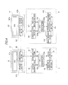
- Fig. 4 is a diagram showing the configurations of the measuring units 41 (M1, M2 and M3), the information processing apparatus 42, the smear preparation apparatus 6 and the transport controller 8.
- the measuring units 41 M1, M2 and M3
- the information processing apparatus 42 the information processing apparatus 42
- the smear preparation apparatus 6 the transport controller 8.
- the transport controller 8 the transport controller 8.
- the measuring unit 41 includes a communication section 411, a bar-code reading section 412, a sample preparation section 413, a pressure generation section 414, a measuring section 415 and a control section 416.
- the communication section 411 communicates with a communication section 422 of the information processing apparatus 42.
- the bar-code reading section 412 reads the bar-code label BL1 of a sample container T taken out into the measuring unit 41.
- the sample preparation section 413 generates a measurement sample by suctioning and discharging the sample (blood) from a sample container T.
- the pressure generation section 414 includes a pneumatic pressure source to supply the pressure for fluid feeding to the sample preparation section 413 and the measuring section 415.
- the measuring section 415 includes a detector such as a flow cytometer, which is used in the blood cell analysis, to generate particle data by processing a detected signal.
- the control section 416 includes a CPU 416a and a storage section 416b.
- the storage section 416b includes storage means such as a ROM and a RAM.
- the storage section 416b stores the particle data obtained by the measuring section 415, the bar-code data read by the bar-code reading section 412 and the like.
- the storage section 416b is also used as a work area for the CPU 416a.
- the CPU 416a controls the sections in accordance with a control program stored in the ROM of the storage section 416b.
- the information processing apparatus 42 includes a control section 421 and a communication section 422.
- the information processing apparatus 42 also includes an interface for performing a video output operation, an interface for performing an input operation from a keyboard or the like and a reading device such as a CD drive or a DVD drive. However, the descriptions thereof will be omitted.
- the control section 421 includes a CPU 421a and a storage section 421b.
- the CPU 421a executes computer programs stored in the storage section 421b.
- the storage section 421b includes storage means such as a ROM, a RAM and a hard disk.
- the communication section 422 performs data communication between the three measuring units 41 and the transport controller 8.
- the CPU 421a performs a blood analysis operation on the basis of the measurement result (particle data) received by the measuring unit 41 and displays the analysis result on the display section 480 (see Fig. 1 ). In addition, the CPU 421a transmits the analysis result to the transport controller 8. Moreover, as described above, the CPU 421a controls the transport of sample racks L on the basis of the detection signals of the various sensors and switches disposed in the sample transport apparatus 3. The CPU 421a also controls the operations of M1, M2 and M3 on the basis of the control command received from the transport controller 8. Such control operation will be described with reference to Fig. 7 .
- the smear preparation apparatus 6 includes a communication section 61, a bar-code reading section 62, a pressure generation section 63, a specimen preparation section 64 and a control section 65.
- the communication section 61 communicates with a communication section 82 of the transport controller 8.
- the bar-code reading section 62 reads the bar-code label BL1 of a sample container T transported to the sample suction position of the smear preparation apparatus 6.
- the pressure generation section 63 includes a pneumatic pressure source to supply the pressure for fluid feeding to the specimen preparation section 64.
- the specimen preparation section 64 prepares a smear by suctioning and discharging the sample (blood) from a sample container T transported to the sample suction position.
- the control section 65 includes a CPU 65a and a storage section 65b.
- the storage section 65b includes storage means such as a ROM and a RAM.
- the storage section 65b stores the bar-code data read by the bar-code reading section 62 and the like.
- the storage section 65b is also used as a work area for the CPU 65a.
- the CPU 65a controls the sections in accordance with a control program stored in the ROM of the storage section 65b.
- the transport controller 8 includes a control section 81 and a communication section 82.
- the transport controller 8 also includes an interface for performing a video output operation, an interface for performing an input operation from a keyboard or the like and a reading device such as a CD drive or a DVD drive.
- the control section 81 includes a CPU 81a and a storage section 81b.
- the CPU 81a executes computer programs stored in the storage section 81b.
- the storage section 81b includes storage means such as a ROM, a RAM and a hard disk.
- the communication section 82 performs data communication between the smear preparation apparatus 6 and the information processing apparatus 42.
- the CPU 81a controls the driving of the three sample transport apparatuses 3 and the sample transport apparatus 5. In addition, the CPU 81a controls the operation of the smear preparation apparatus 6. Moreover, the CPU 81a determines whether the re-examination of M3 is required or not and whether the preparation of a smear is required or not on the basis of the sample analysis result received from the information processing apparatus 42, and controls the operations of M3 and the smear preparation apparatus 6 on the basis of the determination result. Such a control operation will be described with reference to Figs. 5B and 6 .
- Fig. 5A is a diagram showing a processing flow of the transition to an inactive state of the measuring units 41 (M1 M2 and M3) according to this embodiment. The following process is monitored and controlled by the information processing apparatus 42.
- the predetermined condition is that a sample rack L (sample container T) is not detected by the sensors 312a and 312b, the sensors 314a and 314b and the sample container sensor 323.
- a user can change the setting in accordance with the utilization form.
- the predetermined condition may be that a sample rack L (sample container T) is not detected by one or more of the sensors 312a and 312b, the sensors 314a and 314b and the sample container sensor 323.
- a predetermined period of time is 15 minutes in this specification, but also can be changed in accordance with the utilization form. This change is carried out from the input section of the information processing apparatus 42.
- a transition process is performed such that the measuring unit 41 enters an inactive state.
- the inactive state is a state in which the supply of electric power to the pneumatic pressure source in the pressure generation section 414 shown in Fig. 4 is stopped.
- a solenoid valve on the flow path is closed such that a sample and the like are not mixed and then the supply of electric power to the pneumatic pressure source is stopped.
- a transition process is performed so as to achieve an inactive state.
- the supply of electric power to the pneumatic pressure source ( Fig. 4 : pressure generation section 63) is stopped as in the measuring unit 41.
- M3 when the re-examination of a sample is required, M3 is released from the inactive state, and when the preparation of a smear is required, the smear preparation apparatus 6 is released from the inactive state.
- the determination of whether the re-examination is required or not and whether and the preparation of a smear is required or not is performed by the transport controller 8.
- Fig. 5B is a diagram showing a processing flow of the transport controller 8.
- a sample measurement process ( Figs. 6 and 7 ) is performed in parallel to this processing flow and the measurement result is supplied to the transport controller 8 as needed.
- the transport controller 8 transports a sample rack L, which is delivered from the sample delivery unit 21b of the sample input apparatus 2, to the sample transport apparatus 3 in front of M1 or M2. Accordingly, the sample rack L is moved up to the position positioned anterior to the pre-analysis rack holding section 310 of the sample transport apparatus 3 in front of M1 or M2. Continuously, the transport controller 8 drives the rack pushing mechanism 342 to push the sample rack L to the pre-analysis rack holding section 310.
- the sample rack L pushed to the pre-analysis rack holding section 310 is transported along the measurement line L1 as described above and thus positioned at the sample supply position. After that, the measurement is performed by M1 or M2.
- the transport controller 8 determines whether the re-examination of M3 is required or not and whether the preparation of a smear in the smear preparation apparatus 6 is required or not on the basis of the measurement result of M1 or M2. Such a determination is sequentially performed on all the sample containers T held in the sample rack L.
- Fig. 6 is a flowchart showing the detailed processing content of S102.
- a flag A and a flag B are set to 0, respectively.
- S202 it is determined whether or not the result of the measurement performed in M1 or M2 has been supplied from the information processing apparatus 42.
- the measurement result is transmitted to the transport controller 8.
- the transport controller 8 determines whether or not it is required to perform the re-examination on the sample of the sample container T by M3 (S203) and whether or not it is required to perform the preparation of a smear in the smear preparation apparatus 6 (S204) on the basis of the measurement result. Whether the re-examination is required or not and whether the preparation of a smear is required or not are determined by comparing the measurement result of the sample with a predetermined threshold based on the age, sex and the like of a sample provider (patient). The age, sex and the like of the sample provider (patient) are obtained from a host computer on the basis of the bar-code data of the sample container T.
- the transport controller 8 determines whether or not the determination of the necessity of the re-examination and smear preparation has been performed on the samples in all the sample containers T held in the sample rack L (S215). In this determination, when a sample container T which is not subjected to the necessity determination remains (S215: NO), the transport controller 8 return to S202 and waits for the transmission of the measurement result relating to a next sample container T.
- the transport controller 8 inquires of the information processing apparatus 42 whether or not the measurement has been completed in all the sample containers T held in the sample rack L. Regarding this inquiry, when a response of the end of the measurement is gotten from the information processing apparatus 42, the transport controller 8 determines the result is YES in S215.
- the transport controller 8 transmits a measurement instruction indicating that the re-examination in M3 is required, measurement items of the re-examination and bar-code information for specifying a re-examination target sample container T to the information processing apparatus 42. Continuously, the transport controller 8 determines whether a value of the flag A is set to 1 or not (S207). When the value of the flag A is 1 (S207: YES), the process proceeds to S211, and when the value of the flag A is not 1 (S207: NO), the process proceeds to S208. When the value of the flag A is 1, a transmitting process of the estimated arrival time in S209 is already completed and thus the processes of S208 and S209 are skipped.
- the sample container Tf storing the sample which is initially required to be re-examined among the sample containers T.
- the sample rack L is not transported toward M3 until all the samples in the sample containers T stored in the remaining holding sections are measured. In this case, the time required from when it is determined that the sample container Tf is required to be re-examined until the sample rack L arrives at M3 is increased.
- the sample container Tf is held in a holding section (holding position 10) most distant from M3, there are no remaining sample containers T to be measured in the sample rack L and thus the sample rack L is directly transported toward M3. Accordingly, the time required from when it is determined that the sample container Tf is required to be re-examined until the sample rack L arrives at M3 is decreased.
- the time required for the sample rack L to reach M3 is also changed depending on the number of other sample racks L which are present on the transport path to M3. That is, when many other sample racks L are present on such transport path, these sample racks L block the transport path and thus the transport of the sample rack L holding the sample container Tf is disrupted. In this case, the period of time from when the sample rack L is transported toward M3 until the sample rack L arrives at M3 is increased.
- the time required until the sample rack L arrives at M3 is also changed depending on from which one of M1 and M2 the sample rack L is transported. That is, since M1 is more distant from M3 than M2, the period of time from when the sample rack L is transported from M1 until the sample rack L arrives at M3 is longer than the period of time from when the sample rack L is transported from M2 until the sample rack L arrives at M3.
- the amount of time required for the sample rack L holding the sample container Tf to reach M3 is obtained by the transport controller 8, and the estimated arrival time is calculated from this amount of time and the required time.
- the estimated arrival time is transmitted to the information processing apparatus 42 (S209). Continuously, the flag A is set to 1 (S210). In this manner, the transmission of the estimated time of arrival to M3 is stored.
- the transport controller 8 determines whether a value of the flag B is 1 or not.
- the process proceeds to S215, and hen the value of the flag B is not 1 (S212: NO), the process proceeds to S213.
- the value of the flag B is 1, the calculation of the estimated arrival time in S213 is already completed and thus the process of S213 is skipped.
- the estimated time of arrival of the sample rack L holding the sample container T under measurement to the smear preparation apparatus 6 is calculated as in the above-described S208.
- the estimated arrival time is held by the transport controller 8 and the flag B is set to 1 (S214). In this manner, the calculation and holding of the estimated time of arrival to the smear preparation apparatus 6 is stored.
- the calculation of the estimated arrival time in S208 and S213 is performed when the sample container T storing the sample in which it is initially determined that the re-examination is required or the preparation of a smear is required is generated among a plurality of the sample containers T stored in the sample rack L.
- the transport controller 8 when the determination process of the necessity of the re-examinaticn in M3 and the necessity of the preparation of a smear is completed in S102, the transport controller 8 refers to the state of the flag A (S103).
- S103 YES
- the sample container T which is required to be re-examined is held in the sample rack L as a transport target, so the transport controller 8 transports the sample rack L, in which the measurement in M1 or M2 has been completed to the sample transport apparatus 3 in front of M3 (S104).
- the sample rack L is transported along the measurement line L1
- the sample which is required to be re-examined is measured by M3 and the measurement result is transmitted to the transport controller from the information processing apparatus 42 ( Fig. 7 : S313).
- the value of the flag A is not 1 (S103: NO)
- the process proceeds to S106.
- S105 on the basis of the measurement result received from the information processing apparatus 42, the necessity of the preparation of a smear in the smear preparation apparatus 6 is determined. In S105, the process in which the processing steps of S201, S203, and S205 to S210 are omitted in Fig. 6 is performed.
- the transport controller 8 refers to the value of the flag B (S106).
- the transport controller 8 transports the sample rack L in which the measurement of M1 to M3 has been completed to the smear preparation apparatus 6 to prepare a smear (S107).
- the value of the flag B is not 1 (S106: NO)
- the process proceeds to S108. That is, when the value of the flag B is 1, the sample container T in which it is determined that the preparation of a smear is required is included in all the sample containers T held in the sample rack L as a transport target. In this case, the sample rack L is transported to the smear preparation apparatus 6 to prepare a smear of the target sample.
- the smear preparing process will be described with reference to Fig. 8B .
- the transport controller 8 transports the sample rack L to the sample storage apparatus 7. So, the process relating to the sample rack L is completed.
- Fig. 7 is a diagram showing a processing flow of the information processing apparatus 42.
- the sample rack L is pushed to the pre-analysis rack holding section 310 of M1 or M2.
- the information processing apparatus 42 transports the sample rack L pushed to the pre-analysis rack holding section 310 to the sample supply position in M1 or M2 (S301) and the sample stored in a sample container T is measured (S302).
- M1 or M2 transmits the data detected from the sample container T to the information processing apparatus 42.
- the information processing apparatus 42 When receiving the detection data from M1 or M2 (S303: YES), the information processing apparatus 42 analyzes the detection data and obtains the measurement result (S304). Next, the information processing apparatus 42 transmits the obtained measurement result to the transport controller 8 and inquires of the transport controller 8 whether or not re-examination in M3 is required (S305). When the re-examination in M3 is required, a re-examination instruction and measurement items of the re-examination are transmitted from the transport controller 8 in S206 of Fig. 6 .
- the information processing apparatus 42 determines whether the measurement of all the sample containers T held in the sample rack L has been completed or not in M1 or M2 (S306).
- S306: YES the measurement of all the sample containers T held in the sample rack L has been completed
- the process proceeds to S307.
- the measurement of all the sample containers T held in the sample rack L has not been completed (S306: NO)
- the process returns to S301 and the steps S301 to S305 are repeatedly performed until the measurement of all the sample containers T held in the sample rack L is completed.
- the information processing apparatus 42 determines whether or not a sample in which it is determined that the re-examination in M3 is required is included in the sample rack L on the basis of the response to the inquiry in S305 (S307).
- the sample rack L is transported to the pre-analysis rack holding section 310 of M3 in S104 of Fig. 5B .
- the information processing apparatus 42 issues a command to the sample transport apparatus 3 such that the sample rack L which is pushed to the pre-analysis rack holding section 310 as described above is transported toward the sample supply position (S308).
- S307 NO
- the process of the information processing apparatus 42 with respect to the sample rack L is completed.
- the information processing apparatus 42 determines whether M3 is in an inactive state or not (S309). If M3 is in an inactive state when it is determined that the re-examination is required in S102 of Fig. 5B , M3 is subjected to a process of releasing the inactive state. The inactive state releasing process will be described with reference to Fig. 8A .
- the information processing apparatus 42 advances a process of S310 when M3 is not in an inactive state (S309: NO), and waits for the completion of the release of the inactive state of M3 when M3 is in an inactive state (5309: YES).
- S309 NO
- M3 since the release of the inactive state is started at an appropriate timing, M3 is in an active state when the sample container is transported to the sample supply position of M3. Accordingly, the step S309 for waiting for the completion of the release of the inactive state of M3 can be omitted.
- taking the sample in M3 in an inactive state can be prevented when the release of the inactive state takes more time than an assumed time.
- the information processing apparatus 42 issues an instruction so as to advance the measurement of the sample in which it is determined that the re-examination is required.
- the information processing apparatus 42 analyzes the detection data in terms of the designated measurement items and obtains the measurement result (S312). Then, the information processing apparatus 42 transmits the obtained measurement result to the transport controller 8 (S313).
- the transmitted measurement result is used in the determination of the necessity of the preparation of a smear in S105 of Fig. 5B .
- the information processing apparatus 42 determines whether the measurement has been completed in all the sample containers T which are held in the sample rack L and required to be re-examined (S314).
- S314: YES the process of the information processing apparatus 42 with respect to the sample rack L is completed.
- S314: NO the measurement of all the sample containers T which are required to be re-examined has not been completed (S314: NO)
- the process returns to S308.
- the steps S308 to S313 are repeatedly performed until the measurement of all the sample containers T which are required to be re-examined is completed.
- Fig. 8A is a flowchart of the process for releasing the inactive state of M3.
- the transport controller 8 determines that the re-examination in M3 is required, in S208 of Fig. 6 , the estimated time of arrival of the sample rack L under measurement to M3 is calculated and transmitted to the information processing apparatus 42.
- the information processing apparatus 42 determines whether M3 is in an inactive state or not (S402).
- M3 is not in an inactive state (S402: NO)
- the information processing apparatus 42 transmits an instruction for prohibiting the transition to the inactive state to M3 (S403) and the processing flow is completed.
- M3 is in an inactive state (S402: YFS)
- the step S403 for prohibiting shifting of M3 to the inactive state can be omitted.
- the need for starting the release of an inactive state being generated soon after M3 enters the inactive state can be prevented. Accordingly, it is possible to cut power consumption caused by frequent repetition of the transition to an inactive state and the release.
- the information processing apparatus 42 when it is determined that the present time has reached a predetermined time earlier than the estimated arrival time (S404: YES), M3 is instructed to start the release of the inactive state (S405) and the process is completed.
- the predetermined time in S404 is set on the basis of the period of time from when M3 starts the release of the inactive state until the release is completed.
- Fig. 8B is a flowchart showing the content of the smear preparing process in S107 of Fig. 5B . Such a process is performed by the transport controller 8.
- the transport controller 8 transports the sample container T storing the sample in which it is determined that the preparation of a smear is required to the sample suction position of the smear preparation apparatus 6 (S221).
- the transport controller 8 determines whether the smear preparation apparatus 6 is in an inactive state or not (S222).
- a process of releasing the inactive state of the smear preparation apparatus 6 is performed.
- Such inactive state releasing process is performed by the same process as in Fig. 8A . That is, the transport controller 8 determines whether the smear preparation apparatus 6 is in an inactive state or not, and prohibits shifting of the smear preparation apparatus 6 to the inactive state when the smear preparation apparatus is not in the inactive state.
- the transport controller determines whether or not the present time has reached a predetermined time earlier than the estimated arrival time calculated in S102 or S105 of Fig. 5B .
- the transport controller 8 releases the inactive state of the smear preparation apparatus 6.
- step S222 can be omitted as in the case of the above-described step S309. However, by executing this step, taking the sample into the smear preparation apparatus 6 is prevented in an inactive state when the release of the inactive state takes more time than an assumed time.
- the transport controller 8 causes the smear preparation apparatus 6 to prepare a smear of the sample in which it is determined that the preparation of a smear is required.
- the transport controller8 determines whether or not the process has been completed in all the sample containers T in which it is determined that the preparation of a smear is required (S224)
- S224: YES the preparation of a smear is completed.
- S224: NO the process returns to S221.
- the steps S221 to S224 are repeatedly performed until the preparation of a smear is completed in all the sample containers T which are held in the sample rack L and in which it is determined that the preparation of a smear is required.
- M3 and the smear preparation apparatus 6 are not used for a predetermined time, M3 and the smear preparation apparatus 6 are shifted to an inactive state. Accordingly, it is possible to cut power consumption in M3 and the smear preparation apparatus 6.
- the inactive state of M3 is released, and when the preparation of a smear is required by the measurement result of M1 to M3, the inactive state of the smear preparation apparatus 6 is released. Accordingly, even when M3 and the smear preparation apparatus 6 are in an inactive state, the re-examination in M3 and the preparation of a smear in the smear preparation apparatus 6 can be performed without delay.
- the estimated time of arrival of the sample rack L to M3 or the smear preparation apparatus 6 is calculated, and on the basis of the estimated time, the inactive state of M3 and the smear preparation apparatus 6 is released. Accordingly, power consumption of M3 and the smear preparation apparatus 6 can be more effectively cut and the re-examination or the preparation of a smear can be smoothly performed.
- the transport controller 8 determines the necessity of the re-examination and the necessity of the preparation of a smear.
- the information processing apparatus 42 determines these necessities.
- Fig. 9 is a flowchart showing a process of the information processing apparatus 42.
- the steps S305 and S313 (see Fig. 7 ) shown in the first embodiment are replaced with steps S331 and S333, respectively, in this embodiment.
- steps S332 and S334 are added.
- the processing flow is the same as in the above-described first embodiment, except for them.
- the information processing apparatus 42 determines the necessity of the re-examination in M3 and the necessity of the preparation of a smear in the smear preparation apparatus 6, and in S332, the information processing apparatus42 transmits the determination result of the necessities of the re-examination and the preparation of a smear and the bar-code data of the corresponding sample container T to the transport controller 8.
- the information processing apparatus 42 determines the necessity of the preparation of a smear in the smear preparation apparatus 6, and in S334, the information processing apparatus transmits the determination result and the bar-code data of the corresponding sample container T to the transport controller 8.
- the determination of S307 is carried out on the basis of the command received from the transport controller 8. However, in this embodiment, the determination of S307 is carried out on the basis of the result of the determination of the information processing apparatus 42 in S331.
- Fig. 10A is a flowchart showing a process of the transport controller 8 according to this embodiment.
- the steps S102 and S105 shown in the first embodiment are omitted and the steps S103 and S106 are changed into steps S111 and S112, respectively.
- the processing flow is the same as in the above-described first embodiment, except for these changes.
- the transport controller 8 determines whether the re-examination in M3 is required or not on the basis of the determination result transmitted from the information processing apparatus 42 in S332 of Fig. 9 . In addition, in S112, the transport controller 8 determines whether the re-examination in M3 is required or not on the basis of the determination result transmitted from the information processing apparatus 42 in S332 or S334 of Fig. 9 .
- Fig. 10B is a flowchart of processing for releasing the inactive state of M3 or the smear preparation apparatus 6.
- the releasing process for M3 is performed by the information processing apparatus and the releasing process for the smear preparation apparatus 6 is performed by the transport controller 8.
- the inactive state of M3 or the smear preparation apparatus 6 is released.
- the inactive state of M3 or the smear preparation apparatus 6 is released. That is, when the sample container Tf is generated (S411), it is determined whether M3 or the smear preparation apparatus 6 is in an inactive state or not (S412).
- the inactive state is directly released in S413, but in place of this, the inactive state may be released after a certain period of time has elapsed from when it was determined that the re-examination or the preparation of a smear is required.
- a fixed period of time is set by assuming the arrival time of the sample rack L to M3 or the smear preparation apparatus 6.
- the certain period of time may be changed depending on whether the sample rack L is transported to M3 from M1 or M2, or whether the sample rack L is transported to the smear preparation apparatus 6 from M1, M2 or M3.
- the information processing apparatus 42 determines the necessity of the re-examination in M3 and the necessity of the preparation of a smear in the smear preparation apparatus 6. Accordingly, the re-examination in M3 and the preparation of a smear in the smear preparation apparatus 6 can be performed without delay while cutting power consumption of M3 and the smear preparation apparatus 6.
- Fig. 11 is a diagram showing a sample processing system 1.
- a host computer 9 determines the necessity of the re-examination in M3 and the necessity of the preparation of a smear in the smear preparation apparatus 6.
- the host computer 9 has the same configuration as in the information processing apparatus 42 shown in Fig. 4 .
- the host computer 9 is connected to a communication network and can communicate with the information processing apparatus 42, sample input apparatus 2, sample transport apparatus 3, sample storage apparatus 7 and transport controller 8.
- measurement orders are stored on the hard disk of the host computer 9.
- the host computer 9 reads measurement data corresponding to the sample ID from the hard disk and transmits the measurement data to the request source apparatus.
- Fig. 12 is a diagram showing a processing flow of the information processing apparatus 42.
- the steps S331 and S333 (see Fig. 9 ) shown in the above-described second embodiment are replaced with steps S341 and S342, respectively, in this embodiment.
- the processing flow is the same as in the above-described first embodiment, except for this change.
- the information processing apparatus 42 transmits the measurement result of M1 or M2 and inquires of the host computer whether or not the re-examination in M3 is required and whether or not the preparation of a smear in the smear preparation apparatus 6 is required. In response to this, when receiving the determination result from the host computer 9, the information processing apparatus 42 transmits the determination result of the necessity of the preparation of a smear to the transport controller 8 (S332). In addition, in S342, the information processing apparatus 42 transmits the measurement result of M3 to the host computer 9 and inquires of the host computer whether or not the preparation of a smear in the smear preparation apparatus 6 is required. In response to this, when receiving the determination result from the host computer 9, the information processing apparatus 42 transmits the determination result to the transport controller 8 (S334).
- blood is exemplified as a measurement target.
- urine may be a measurement target. That is, the present invention also can be applied to sample processing apparatuses examining urine and can be further applied to clinical sample examining apparatuses examining other clinical samples.
- the sample rack L when estimated arrival time is calculated on the assumption that the sample rack L passes through the skip line L2 without passing through the measurement line L1 of M3 so as to be transported to the smear preparation apparatus 6, the sample rack L actually passes through the measurement line L1 of M3 and thus the calculated estimated arrival time is earlier than the estimated arrival time of the case where a re-examination is performed in M3. Accordingly, in this case, at a timing at which it is determined that the sample in the fifth sample container T is required to be re-examined, the sample rack L may pass through the measurement line L1 of M3 such that the estimated time of arrival to the smear preparation apparatus 6 is modified.
- the estimated arrival time of a sample rack L is not calculated.
- the measurement result of M1 to M3 may be transmitted from the information processing apparatus 42 to the transport controller 8 and the transport controller 8 may calculate the estimated arrival time of a sample rack L as in the above-described first embodiment.
- such a calculation of the estimated arrival time may be performed in the information processing apparatus 42.
- a notch 3a may be provided in the sample transport apparatus 3 in front of M3. Accordingly, when a sample re-examined in M3 is further subjected to the preparation of a smear, the rack slider 52 may be positioned at the position of Fig. 13 so as to send the sample rack L to the rack transport passage 51a via the notch 3a.
- the inactive state is a state in which the supply of electric power to the pneumatic pressure source is stopped.
- the supply of electric power to another constituent section may be stopped or decreased.
- a warming mechanism or the like for warming a sample, reagent and the like a cooling mechanism for cooling a sample, reagent and the like
- the supply amount of electric power may be increased such that the heater has a temperature at the time of warming. In this manner, while cutting power consumption, the interruption of the sample process occurring waiting for the heater to warm up can be avoided.
- a rubber heater can be used. Since the power consumption of the rubber heater is large, the effect of the present invention is particularly large.
- the inactive state is a state in which the supply of electric power to the pneumatic pressure source is stopped.
- the inactive state may be a state that the supply of electric power to the entire measuring unit or the entire smear preparation apparatus is stopped, that is, a state that the measuring unit or the smear preparation apparatus is powered-off.
- a transition process to a power-off state of the measuring unit or the smear preparation apparatus may be automatically executed when a predetermined time has elapsed after operation situations was monitored and a predetermined condition was met as in the above-described three embodiments, or may be executed in response to the operation of a power switch by a user of the sample processing system.
- the transition to an inactive state by a user also can be executed in response to a power-off instruction input to the information processing apparatus in place of the power switch.
- the release of the inactive state is executed when the measuring unit or the smear preparation apparatus is started and enters a state (standby state) in which the measurement or the preparation of a smear can be performed.
- the power consumption cutting effect is larger than in the case where the electric power supply is partially stopped, as in the case where only the supply of electric power to the pneumatic pressure source is stopped.
- the measuring unit or the smear preparation apparatus is shifted to an inactive state.
- the sample transport apparatus in front of the measuring unit M3 or the sample transport apparatus in front of the smear preparation apparatus may be shifted to an inactive state.
- the transition to an inactive state may be carried out when a predetermined period of time elapses after a predetermined condition has been met, and the inactive state may be released when the determination result showing that an additional process is required is obtained.
Abstract
at least one processor; and
at least one memory that stores programs executable collectively by the at least one processor to:
transport sample containers through a conveying path along which there are arranged at least one first module for testing of samples and at least one second module for processing of samples which have been tested by the at least one first module, wherein the at least one second module is switchable between an active state and an inactive state;
obtain a determination result whether a sample which have been tested by the at least one first module is necessary to be processed by the at least one second module;
if the sample has been determined necessary to be processed by the at least one second module, transport a sample container containing the sample to the at least one second module for processing; and
if the at least one second module is in the inactive state, place the at least one second module in the active state to make it ready to process the sample.
Description
- The present invention relates to a sample processing system, method and non-transitory storage medium for performing a predetermined process such as examination or analysis on a sample such as blood.
- Sample processing apparatuses for processing a clinical sample such as blood or urine are used in medical institutions such as hospitals. Some of such sample processing apparatuses are composed of a plurality of analysis modules and a transport apparatus for transporting a sample to the plurality of analysis modules, so as to improve the sample processing capacity. In addition, some of such sample processing apparatuses are configured such that, when it is determined that the same sample is required to be re-examined as a result of the analysis (first examination) in one analysis module, the re-examination is automatically carried out in another module in the same apparatus (for example, see
U.S. patent application publication No. 2008/0310999 ). - In addition, some of this type of sample processing apparatuses has a function of changing a state of the apparatus into an inactive state in order to suppress power consumption (for example, see Japanese laid-open patent publication No.
2003-121449 - In the sample processing apparatus which is configured so as to carry out the re-examination as in the above-mentioned
U.S. patent application publication No. 2008/0310999 , the usage frequency of an analysis module for use in the re-examination is smaller than that of another analysis module for carrying out first examination in many cases. Particularly, in a time period in which the number of samples is small, the time in which the analysis module for use in the re-examination is not used increases. However, even in this situation, the analysis module for use in the re-examination is made active so as to be able to promptly start the re-examination in the conventional sample processing apparatus. Accordingly, a problem occurs in that the power consumption increases. - In Japanese laid-open patent publication No.
2003-121449 - The scope of the present invention is defined solely by the appended claims, and is not affected to any degree by the statements within this summery.
- (1) A first aspect of this invention is a sample processing system comprising at least one processor and at least one memory that stores programs executable collectively by the at least one processor to:
- transport sample containers through a conveying path along which there are arranged at least one first module for testing of samples and at least one second module for processing of samples which have been tested by the at least one first module, wherein the at least one second module is switchable between an active state and an inactive state;
- obtain a determination result whether a sample which have been tested by the at least one first module is necessary to be processed by the at least one second module;
- if the sample has been determined necessary to be processed by the at least one second module, transport a sample container containing the sample to the at least one second module for processing; and
- if the at least one second module is in the inactive state, place the at least one second module in the active state to make it ready to process the sample.
- According to the sample processing system of this aspect, power consumption of the at least one second module is cut and a process of the at least one second module can be executed without delay.
- (2) The sample processing system according to (1), wherein the inactive state is defined as a state where a supply of electricity is halted to a pressure source in the second module for generating an air pressure.
- (3) The sample processing system according to (1), wherein the inactive state is defined as a state where a supply of electricity is either halted or reduced to at least one of a heater for heating a reagent and a cooler for cooling a reagent.
- (4) The sample processing system according to (1), wherein the inactive state is defined as a state where the second module is turned off.
- (5) The sample processing system according to any one of (1) through (4), wherein the at least one processor monitors activity of the respective at least one second measurement module; and, and places a second module in the inactive state a predetermined time after a last activity thereof is observed.
- (6) The sample processing system according to (5), wherein the at least one processor monitors the activity of the respective at least one second module by monitoring sensors arranged along the conveying path for detecting the sample on the conveying path.
- (7) The sample processing system according to (6), wherein the conveying path comprises a roundabout path for the respective modules in order to load a sample on the respective measurement modules, and processor monitors sensors arranged along the roundabout path for the respective at least one second module.
- (8) The sample processing system according to any one of (1) through (7), wherein the at least one second module is a smear preparation apparatus.
- (9) The sample processing system according to (8), wherein the inactive state is defined as a state where a supply of electricity is halted to a pressure source in the smear preparation apparatus for generating an air pressure.
- (10) The sample processing system according to any one of (1) through (7), wherein the sample is blood and the first and second module analyze blood cells in the blood.
- (11) The sample processing system according to (10), wherein the first module conducts an initial testing of the sample, and the second module conducts a re-testing of the sample.
- (12) The sample processing system according to any one of (1) through (11), wherein the at least one processor places the at least one second module in the active state to make it ready to process the sample a predetermined time after obtaining the determination result.
- (13) The sample processing system according to any on of (1) through (12), wherein the at least one processor is connected to a host computer via a communication network, wherein the host computer determines whether the sample which has been tested by the at least one first module is necessary to be processed by the at least one second module, and the at least one processor obtains the determination result from the host computer.
- (14) A second aspect of this invention is a method for saving electricity consumed by a sample processing system, the method comprising steps of:
- transporting sample containers through a conveying path along which there are arranged at least one first module for testing of samples and at least one second module for processing of samples which have been tested by the at least one first module, wherein the at least one second module is switchable between an active state and an inactive state;
- obtaining a determination result whether a sample which have been tested by the at least one first module is necessary to be processed by the at least one second module;
- if the sample has been determined necessary to be processed by the at least one second module, transporting a sample container containing the sample to the at least one second module for processing; and
- if the at least one second module is in the inactive state, placing the at least one second module in the active state to make it ready to process the sample.
- According to the method for saving electricity consumed by a sample processing system of this aspect, power consumption of the at least one second module is cut and a process of the at least one second module can be executed without delay.
- (15) A third aspect of this invention is a non-transitory storage medium which stores programs executable collectively by at least one processor of a sample processing system to:
- transport sample containers through a conveying path along which there are arranged at least one first module for testing of samples and at least one second module for processing of samples which have been tested by the at least one first module, wherein the at least one second module is switchable between an active state and an inactive state;
- obtain a determination result whether a sample which have been tested by the at least one first module is necessary to be processed by the at least one second module;
- if the sample has been determined necessary to be processed by the at least one second module, transport a sample container containing the sample to the at least one second module for processing; and
- if the at least one second module is in the inactive state, place the at least one second module in the active state to make it ready to process the sample.
- According to the on-transitory storage medium of this aspect, power consumption of the at least one second module is cut and a process of the at least one second module can be executed without delay.
- The effect and meaning of the present invention will be further clear by descriptions of the following embodiments. However, the following embodiments are an example when the present invention is embodied, and the present invention is not limited by the following embodiments.
-
-
Fig. 1 is a diagram showing the configuration of a sample processing system according to a first embodiment. -
Fig. 2A and 2B show perspective views showing the appearances of a sample container and a sample rack. -
Fig. 3 is a top view showing the configuration of a sample transport apparatus according to the first embodiment. -
Fig. 4 is a diagram showing the configurations of a measuring unit, an information processing apparatus, a smear preparation apparatus and a transport controller. -
Fig. 5A is a flowchart showing a transition process to an inactive state according to the first embodiment. -
Fig. 5B is a flowchart showing a process of the transport controller according to the first embodiment. -
Fig. 6 is a flowchart showing the content of the process of S102 ofFig. 5B . -
Fig. 7 is a flowchart showing a process of the information processing apparatus according to the first embodiment. -
Fig. 8A is a flowchart showing an inactive state releasing process according to the first embodiment. -
Fig. 8B is a flowchart showing the content of the process of S107 ofFig. 5B . -
Fig. 9 is a flowchart showing a process of an information processing apparatus according to a second embodiment. -
Fig. 10A is a flowchart showing a process of a transport controller according to the second embodiment. -
Fig. 10B is a flowchart showing an inactive state releasing process according to the second embodiment. -
Fig. 11 is a diagram showing the configuration of a sample processing system according to a third embodiment. -
Fig. 12 is a flowchart showing a process of an information processing apparatus according to the third embodiment. -
Fig. 13 is a diagram showing the configuration of a sample processing system according to a modified embodiment. - The present embodiment is a sample processing system for performing examination and analysis on blood, to which the present invention is applied. A sample processing system according to this embodiment includes three measuring units and one smear preparation apparatus. Blood analyses are performed in parallel by two of the three measuring units, and when re-examination is required on the basis of the analysis result, the remaining one measuring unit performs the measurement. When it is necessary to prepare a smear on the basis of the analysis result of the three measuring units, a smear is prepared by the smear preparation apparatus.
- Hereinafter, a sample processing apparatus according to a first embodiment will be described with reference to the drawings.
-
Fig. 1 is a top view showing the configuration of asample processing system 1, when viewed from the upper side. Thesample processing system 1 according to this embodiment includes asample input apparatus 2, threesample transport apparatuses 3, a bloodcell analysis apparatus 4, asample transport apparatus 5, asmear preparation apparatus 6, asample storage apparatus 7 and atransport controller 8. - The
sample input apparatus 2 includes twosample delivery units code reading unit 22 which is disposed between the twosample delivery units sample delivery units -
Figs. 2A and 2B are a perspective view showing the appearance of a sample container and a perspective view showing the appearance of a sample rack, respectively. - Referring to
Fig. 2A , a sample container T is a tubular container made of translucent glass or synthetic resin and is open at the upper end thereof. A blood sample collected from a patient is stored in the sample container and the opening at the upper end is sealed with a cap section C. A bar-code label BL1 is adhered to the side surface of the sample container T. A bar-code indicating a sample LID is printed on the bar-code label BL1. - Referring to
Fig. 2B , in a sample rack L, ten holding sections are formed so as to vertically (uprightly) hold ten sample containers T side by side. A bar-code label BL2 is adhered to the side surface of the sample rack L. A bar-code indicating a rack ID is printed on the bar-code label BL2. - Returning to
Fig. 1 , thesample delivery unit 21a sequentially delivers placed sample racks L to the bar-code reading unit 22. The bar-code reading unit 22 reads a rack ID from the bar-code of the bar-code label BL2 adhered to the sample rack L delivered from thesample delivery unit 21a. In addition, the bar-code reading unit 22 reads a sample ID from the bar-code of the bar-code label BL1 adhered to the sample container T stored in the sample rack L. Moreover, the bar-code reading unit 22 delivers the sample rack L in which the reading has been completed to thesample delivery unit 21b. Thesample delivery unit 21b sequentially delivers the sample racks L delivered from the bar-code reading unit 22 to thesample transport apparatus 3. - As shown in the drawing, the three
sample transport apparatuses 3 are disposed in front of three measuringunits 41, respectively. The two neighboringsample transport apparatuses 3 are connected to each other. The right end of the rightsample transport apparatus 3 is connected to thesample delivery unit 21a of thesample input apparatus 2 and the left end of the leftsample transport apparatus 3 is connected to thesample transport apparatus 5. As shown in the drawing, a notch is formed at both front ends of eachsample transport apparatus 3 so as to transfer a sample rack L. - These three
sample transport apparatuses 3 divide the cases into cases in which sample measurement is carried out and cases in which sample measurement is not carried out in the corresponding measuringunits 41, respectively, to transport sample racks L by two transport paths. That is, as shown in the drawing, when the measuringunit 41 carries out sample measurement, a sample rack L is transported along the rear dashed-line arrow, and when the measuringunit 41 does not carry out sample measurement, a sample rack L is transported along the front dashed-line arrow. - The
transport controller 8 controls thesample transport apparatus 3 when transporting a sample rack L along the front dashed-line arrow. In addition, aninformation processing apparatus 42 controls thesample transport apparatus 3 when transporting a sample rack L along the rear dashed-line arrow. - The blood
cell analysis apparatus 4 is an optical flow cytometry type multiple blood cell analysis apparatus and includes the three measuringunits 41 and theinformation processing apparatus 42. Hereinafter, for the sake of convenience, the three measuringunits 41 will be referred to as M1, M2 and M3 sequentially from the right. - M1, M2 and M3 measures the blood sample stored in a sample container T. That is, each of M1, M2 and M3 takes out the sample container T from the sample rack L at a predetermined position on the transport path of the
sample transport apparatus 3 disposed in front of the measuring unit. The blood sample stored in the sample container T is measured in M1, M2 and M3. When the measurement in M1, M2 and M3 is completed, the sample container T returns to the original holding section of the sample rack L. - The sample racks L which are sequentially delivered from the
sample delivery unit 21b of thesample input apparatus 2 are alternately transported to M1 and M2. In this manner, two sample racks L can be measured in parallel by M1 and M2 and the entire measurement process is improved. - M3 is a measuring unit which is used in the re-examination. Whether re-measurement of M3 is required or not is determined in accordance with the measurement result of M1 or M2. When it is determined that re-examination is required by M1 or M2, the sample rack L storing a re-examination target sample is transported so as to perform the re-examination by M3. In this embodiment, such a determination is performed by the
transport controller 8. - The
information processing apparatus 42 is connected so as to communicate with the three measuring units 41 (M1, M2 and M3) and thetransport controller 8. Theinformation processing apparatus 42 controls the operations of the three measuring units 41 (M1, M2 and M3). In addition, theinformation processing apparatus 42 displays the analysis result based on the result of the measurement performed by the three measuring units 41 (M1, M2 and M3) on adisplay section 480. As theinformation processing apparatus 42, for example, a separate personal computer or a computer incorporated in the system can be used. - The
sample transport apparatus 5 is disposed in front of thesmear preparation apparatus 6 and includes aconveyor 51 and arack slider 52. Thetransport apparatus 5 includes acontrol section 51c to control the operations of theconveyor 51 and therack slider 52 in accordance with the command from thetransport controller 8. - The
conveyor 51 is provided with tworack transport passages rack transport passage 51a near thesmear preparation apparatus 6 is a measurement line for transporting a sample rack L which stores a sample to be used to prepare a smear by thesmear preparation apparatus 6. On the other hand, therack transport passage 51b away from thesmear preparation apparatus 6 is a skip line for transporting a sample rack L which does not store a sample to be used to prepare a smear by thesmear preparation apparatus 6. - The
rack slider 52 is disposed at the right end of theconveyor 51 and is configured so as to be movable in a front-back direction. Due to the movement of therack slider 52 in the front-back direction, a sample rack L which is delivered from thesample transport apparatus 3 disposed in front of M3 is delivered to therack transport passage rack slider 52. - The sample rack L passing through the
sample transport apparatus 3 in front of M3 is stored in therack slider 52. When distributing the sample rack L to therack transport passage 51a, therack slider 52 moves backward while storing the sample rack L and is positioned at the right side of therack transport passage 51a. Then, therack slider 52 pushes the sample rack L to therack transport passage 51a. In this manner, the sample rack L is delivered to therack transport passage 51a. On the other hand, when the sample rack L is distributed to therack transport passage 51b, therack slider 52 does not move backward and pushes the sample rack L to therack transport passage 51b. - In the
smear preparation apparatus 6, a smear of a blood sample is prepared. That is, first, thesmear preparation apparatus 6 suctions a blood sample stored in a sample container T at a predetermined position on therack transport passage 51a. Continuously, the suctioned blood sample is dropped onto a glass slide, thinly extended on the glass slide and then is dried. After that, a liquid dye is supplied to the glass slide to dye the blood on the glass slide and a smear is prepared. - Whether the preparation of a smear is required or not is determined in accordance with the measurement result of the three measuring units 41 (M1, M2 and M3). When it is determined that the preparation of a smear is required by the three measuring units 41 (M1, M2 and M3), the sample rack L storing a target sample is transported to the
rack transport passage 51a so as to prepare a smear in thesmear preparation apparatus 6. In this embodiment, such a determination is performed by thetransport controller 8. - The
sample storage apparatus 7 is configured such that a plurality of sample racks L are placed therein. Thesample storage apparatus 7 receives and stores a sample rack L, in which the analysis or the preparation of a smear has been completed, from therack transport passage conveyor 51. Thesample storage apparatus 7 may be configured such that sample racks L passing through therack transport passage 51a and sample racks L passing through therack transport 51b are distinguished and stored. In this manner, a user can easily distinguish the sample racks L from which the smear has been prepared from the sample racks L from which the smear has not been prepared. - The
transport controller 8 controls the driving of the threesample transport apparatuses 3 and thesample transport apparatus 5, and monitors and controls thesmear preparation apparatus 6. In addition, in order to properly transport a sample rack L, thetransport controller 8 is connected to thesample input apparatus 2, theinformation processing apparatus 42 and thesample storage apparatus 7 so as to communicate therewith. As thetransport controller 8, for example, a separate personal computer or a computer incorporated in the system can be used. -
Fig. 3 is a top view showing the configuration of thesample transport apparatus 3, when viewed from the upper side. Thesample transport apparatus 3 includes a pre-analysisrack holding section 310, arack transport section 320, a post-analysisrack holding section 330 and arack transport section 340. - In the case where the measurement is performed on a sample rack L, the sample rack L is sent to the lower-right position shown by the broken line in
Fig. 3 . After that, arack pushing mechanism 342 moves backward and pushes the sample rack L to the front end of the pre-analysisrack holding section 310. When this state is detected byoptical sensors rack feeding mechanisms rack transport section 320, aswitch 321 is turned on. In response to this,belts rack feeding mechanisms - Then, the sample rack L arrives at the position of a
sample container sensor 323. Thesample container sensor 323 is a contact-type sensor. When a detection target sample container T, which is held in the sample rack L, passes through the position under thesample container sensor 323, the contact piece of thesample container sensor 323 is bent by the sample container T and thus the existence of the sample container T is detected. - At a position (hereinafter, referred to as "the sample supply position") positioned on the left side of the position, at which the sample container T has been detected by the
sample container sensor 323, by a distance corresponding to one sample container, a hand section of the measuringunit 41 grips the sample container T and takes out the sample container T from the sample rack L. The removed sample container T returns to the sample rack L after used in the measurement in the measuringunit 41. The transport of the sample rack L stands by until the sample container T returns to the sample rack L. - In this manner, when the measurement of the samples in all of the sample containers T held in the sample rack L is completed, the sample rack L is sent up to the left end position of the
rack transport section 320 shown by the broken line inFig. 3 by thebelts optical sensors belts rack holding section 330 by arack pushing mechanism 325. - Then, rack feeding
mechanisms rack transport section 340. - In the case where the measurement is not performed on the sample rack L, the sample rack L is directly sent to the left end from the right end of the
rack transport section 340 by abelt 341. - By controlling the transport of the sample rack L as described above, in the
sample transport apparatus 3, a measurement line L1 as a transport line of the sample racks L routed through the sample supply position, and a skip line L2 as a transport line for directly carrying the sample racks L, carried from the right side without routed through the sample supply position, to the left apparatus are formed. -
Sensors rack transport passage 340 and therack transport section 320 and on atransport passage 311 of the pre-analysisrack holding section 310.Sensors rack transport passage 340 and therack transport section 320 and on atransport passage 331 of the post-analysisrack holding section 330. -
Fig. 4 is a diagram showing the configurations of the measuring units 41 (M1, M2 and M3), theinformation processing apparatus 42, thesmear preparation apparatus 6 and thetransport controller 8. InFig. 4 , for the sake of convenience, only one measuringunit 41 is shown. However, other measuringunits 41 also have the same configuration. - The measuring
unit 41 includes acommunication section 411, a bar-code reading section 412, asample preparation section 413, apressure generation section 414, a measuringsection 415 and acontrol section 416. - The
communication section 411 communicates with acommunication section 422 of theinformation processing apparatus 42. The bar-code reading section 412 reads the bar-code label BL1 of a sample container T taken out into the measuringunit 41. - The
sample preparation section 413 generates a measurement sample by suctioning and discharging the sample (blood) from a sample container T. Thepressure generation section 414 includes a pneumatic pressure source to supply the pressure for fluid feeding to thesample preparation section 413 and themeasuring section 415. The measuringsection 415 includes a detector such as a flow cytometer, which is used in the blood cell analysis, to generate particle data by processing a detected signal. Thecontrol section 416 includes aCPU 416a and astorage section 416b. Thestorage section 416b includes storage means such as a ROM and a RAM. Thestorage section 416b stores the particle data obtained by the measuringsection 415, the bar-code data read by the bar-code reading section 412 and the like. In addition, thestorage section 416b is also used as a work area for theCPU 416a. TheCPU 416a controls the sections in accordance with a control program stored in the ROM of thestorage section 416b. - The
information processing apparatus 42 includes acontrol section 421 and acommunication section 422. Theinformation processing apparatus 42 also includes an interface for performing a video output operation, an interface for performing an input operation from a keyboard or the like and a reading device such as a CD drive or a DVD drive. However, the descriptions thereof will be omitted. - The
control section 421 includes aCPU 421a and astorage section 421b. TheCPU 421a executes computer programs stored in thestorage section 421b. Thestorage section 421b includes storage means such as a ROM, a RAM and a hard disk. Thecommunication section 422 performs data communication between the three measuringunits 41 and thetransport controller 8. - The
CPU 421a performs a blood analysis operation on the basis of the measurement result (particle data) received by the measuringunit 41 and displays the analysis result on the display section 480 (seeFig. 1 ). In addition, theCPU 421a transmits the analysis result to thetransport controller 8. Moreover, as described above, theCPU 421a controls the transport of sample racks L on the basis of the detection signals of the various sensors and switches disposed in thesample transport apparatus 3. TheCPU 421a also controls the operations of M1, M2 and M3 on the basis of the control command received from thetransport controller 8. Such control operation will be described with reference toFig. 7 . - The
smear preparation apparatus 6 includes acommunication section 61, a bar-code reading section 62, apressure generation section 63, aspecimen preparation section 64 and acontrol section 65. - The
communication section 61 communicates with acommunication section 82 of thetransport controller 8. The bar-code reading section 62 reads the bar-code label BL1 of a sample container T transported to the sample suction position of thesmear preparation apparatus 6. - The
pressure generation section 63 includes a pneumatic pressure source to supply the pressure for fluid feeding to thespecimen preparation section 64. Thespecimen preparation section 64 prepares a smear by suctioning and discharging the sample (blood) from a sample container T transported to the sample suction position. Thecontrol section 65 includes aCPU 65a and astorage section 65b. Thestorage section 65b includes storage means such as a ROM and a RAM. Thestorage section 65b stores the bar-code data read by the bar-code reading section 62 and the like. In addition, thestorage section 65b is also used as a work area for theCPU 65a. TheCPU 65a controls the sections in accordance with a control program stored in the ROM of thestorage section 65b. - The
transport controller 8 includes acontrol section 81 and acommunication section 82. Thetransport controller 8 also includes an interface for performing a video output operation, an interface for performing an input operation from a keyboard or the like and a reading device such as a CD drive or a DVD drive. - The
control section 81 includes aCPU 81a and astorage section 81b. TheCPU 81a executes computer programs stored in thestorage section 81b. Thestorage section 81b includes storage means such as a ROM, a RAM and a hard disk. Thecommunication section 82 performs data communication between thesmear preparation apparatus 6 and theinformation processing apparatus 42. - The
CPU 81a controls the driving of the threesample transport apparatuses 3 and thesample transport apparatus 5. In addition, theCPU 81a controls the operation of thesmear preparation apparatus 6. Moreover, theCPU 81a determines whether the re-examination of M3 is required or not and whether the preparation of a smear is required or not on the basis of the sample analysis result received from theinformation processing apparatus 42, and controls the operations of M3 and thesmear preparation apparatus 6 on the basis of the determination result. Such a control operation will be described with reference toFigs. 5B and6 . -
Fig. 5A is a diagram showing a processing flow of the transition to an inactive state of the measuring units 41 (M1 M2 and M3) according to this embodiment. The following process is monitored and controlled by theinformation processing apparatus 42. - In S1, by the
control section 416 shown inFig. 4 , the operation situations of the measuringunit 41 and thesample transport apparatus 3 positioned in front of the measuringunit 41 are monitored. - In S2, in the monitoring of the operation situations, it is determined whether or not a predetermined period of time (15 minutes) has elapsed after a predetermined condition was met. When it is determined that a predetermined period of time (15 minutes) has elapsed (S2: YES), the process proceeds to S3. When it is determined that a predetermined period of time (15 minutes) has not elapsed (S2: NO), the process returns to S1 and the monitoring of the operation situations is continued.
- Here, the predetermined condition is that a sample rack L (sample container T) is not detected by the
sensors sensors sample container sensor 323. Regarding such predetermined condition, a user can change the setting in accordance with the utilization form. For example, the predetermined condition may be that a sample rack L (sample container T) is not detected by one or more of thesensors sensors sample container sensor 323. In addition, a predetermined period of time is 15 minutes in this specification, but also can be changed in accordance with the utilization form. This change is carried out from the input section of theinformation processing apparatus 42. - In S3, a transition process is performed such that the measuring
unit 41 enters an inactive state. Here, the inactive state is a state in which the supply of electric power to the pneumatic pressure source in thepressure generation section 414 shown inFig. 4 is stopped. In greater detail, when the transition process to the inactive state is started, a solenoid valve on the flow path is closed such that a sample and the like are not mixed and then the supply of electric power to the pneumatic pressure source is stopped. - Also in the
smear preparation apparatus 6, when a predetermined condition, such as the passing of a predetermined period of time without the creation of a smear, is met as in the above-describedmeasuring unit 41, a transition process is performed so as to achieve an inactive state. When thesmear preparation apparatus 6 is shifted to an inactive state, the supply of electric power to the pneumatic pressure source (Fig. 4 : pressure generation section 63) is stopped as in the measuringunit 41. - Next, processes of the
transport controller 8 and theinformation processing apparatus 42 will be described with reference to the flowcharts shown inFigs. 5B ,6 ,7 and8 . - In this embodiment, when the re-examination of a sample is required, M3 is released from the inactive state, and when the preparation of a smear is required, the
smear preparation apparatus 6 is released from the inactive state. The determination of whether the re-examination is required or not and whether and the preparation of a smear is required or not is performed by thetransport controller 8. -
Fig. 5B is a diagram showing a processing flow of thetransport controller 8. A sample measurement process (Figs. 6 and7 ) is performed in parallel to this processing flow and the measurement result is supplied to thetransport controller 8 as needed. - In S101, the
transport controller 8 transports a sample rack L, which is delivered from thesample delivery unit 21b of thesample input apparatus 2, to thesample transport apparatus 3 in front of M1 or M2. Accordingly, the sample rack L is moved up to the position positioned anterior to the pre-analysisrack holding section 310 of thesample transport apparatus 3 in front of M1 or M2. Continuously, thetransport controller 8 drives therack pushing mechanism 342 to push the sample rack L to the pre-analysisrack holding section 310. - The sample rack L pushed to the pre-analysis
rack holding section 310 is transported along the measurement line L1 as described above and thus positioned at the sample supply position. After that, the measurement is performed by M1 or M2. - In S102, the
transport controller 8 determines whether the re-examination of M3 is required or not and whether the preparation of a smear in thesmear preparation apparatus 6 is required or not on the basis of the measurement result of M1 or M2. Such a determination is sequentially performed on all the sample containers T held in the sample rack L. -
Fig. 6 is a flowchart showing the detailed processing content of S102. - In S201, a flag A and a flag B are set to 0, respectively.
- In S202, it is determined whether or not the result of the measurement performed in M1 or M2 has been supplied from the
information processing apparatus 42. Here, in addition to the bar-code data read from a measurement target sample container T, the measurement result is transmitted to thetransport controller 8. - When the measurement result relating to a predetermined sample container T is received from the information processing apparatus 42 (S202: YES), the
transport controller 8 determines whether or not it is required to perform the re-examination on the sample of the sample container T by M3 (S203) and whether or not it is required to perform the preparation of a smear in the smear preparation apparatus 6 (S204) on the basis of the measurement result. Whether the re-examination is required or not and whether the preparation of a smear is required or not are determined by comparing the measurement result of the sample with a predetermined threshold based on the age, sex and the like of a sample provider (patient). The age, sex and the like of the sample provider (patient) are obtained from a host computer on the basis of the bar-code data of the sample container T. - When the re-examination and the preparation of a smear are not required as a result of the determination of S203 and S204 (S205: NO, S211: NO), the
transport controller 8 determines whether or not the determination of the necessity of the re-examination and smear preparation has been performed on the samples in all the sample containers T held in the sample rack L (S215). In this determination, when a sample container T which is not subjected to the necessity determination remains (S215: NO), thetransport controller 8 return to S202 and waits for the transmission of the measurement result relating to a next sample container T. - In the determination of S215, the
transport controller 8 inquires of theinformation processing apparatus 42 whether or not the measurement has been completed in all the sample containers T held in the sample rack L. Regarding this inquiry, when a response of the end of the measurement is gotten from theinformation processing apparatus 42, thetransport controller 8 determines the result is YES in S215. - When the determination result in S203 is "the re-examination is required" (S205: YES), the
transport controller 8 transmits a measurement instruction indicating that the re-examination in M3 is required, measurement items of the re-examination and bar-code information for specifying a re-examination target sample container T to theinformation processing apparatus 42. Continuously, thetransport controller 8 determines whether a value of the flag A is set to 1 or not (S207). When the value of the flag A is 1 (S207: YES), the process proceeds to S211, and when the value of the flag A is not 1 (S207: NO), the process proceeds to S208. When the value of the flag A is 1, a transmitting process of the estimated arrival time in S209 is already completed and thus the processes of S208 and S209 are skipped. - In S208, depending on the holding position of the sample container T storing the sample which becomes a re-examination target in the sample rack L, the estimated time of arrival to M3 of the sample rack L holding the sample container T under measurement is calculated.
- For example, such a calculation of the estimated arrival time is performed as follows.
- As shown in
Figs. 2A and 2B , ten holding sections are formed in the sample rack L. Accordingly, when the sample containers T held in the sample rack L are sequentially subjected to the measurement from the end, the time required for the sample rack L to reach M3 is changed depending on the holding section of the sample container T (hereinafter, this sample container will be particularly referred to as "the sample container Tf") storing the sample which is initially required to be re-examined among the sample containers T. - For example, when the sample container Tf is held in a holding section (holding position 1) closest to M3, the sample rack L is not transported toward M3 until all the samples in the sample containers T stored in the remaining holding sections are measured. In this case, the time required from when it is determined that the sample container Tf is required to be re-examined until the sample rack L arrives at M3 is increased. On the other hand, when the sample container Tf is held in a holding section (holding position 10) most distant from M3, there are no remaining sample containers T to be measured in the sample rack L and thus the sample rack L is directly transported toward M3. Accordingly, the time required from when it is determined that the sample container Tf is required to be re-examined until the sample rack L arrives at M3 is decreased.
- In addition, the time required for the sample rack L to reach M3 is also changed depending on the number of other sample racks L which are present on the transport path to M3. That is, when many other sample racks L are present on such transport path, these sample racks L block the transport path and thus the transport of the sample rack L holding the sample container Tf is disrupted. In this case, the period of time from when the sample rack L is transported toward M3 until the sample rack L arrives at M3 is increased.
- The time required until the sample rack L arrives at M3 is also changed depending on from which one of M1 and M2 the sample rack L is transported. That is, since M1 is more distant from M3 than M2, the period of time from when the sample rack L is transported from M1 until the sample rack L arrives at M3 is longer than the period of time from when the sample rack L is transported from M2 until the sample rack L arrives at M3.
- In S208, in consideration of these change factors, the amount of time required for the sample rack L holding the sample container Tf to reach M3 is obtained by the
transport controller 8, and the estimated arrival time is calculated from this amount of time and the required time. The estimated arrival time is transmitted to the information processing apparatus 42 (S209). Continuously, the flag A is set to 1 (S210). In this manner, the transmission of the estimated time of arrival to M3 is stored. - On the basis of the measurement result received from the
information processing apparatus 42, when it is determined that the preparation of a smear is required in S204 (S211: YES), the process proceeds to S212. When it is determined that the preparation of a smear is not required (S211: NO), the process proceeds to S215. - In S212, the
transport controller 8 determines whether a value of the flag B is 1 or not. Here, when the value of the flag B is 1 (S212: YES), the process proceeds to S215, and hen the value of the flag B is not 1 (S212: NO), the process proceeds to S213. When the value of the flag B is 1, the calculation of the estimated arrival time in S213 is already completed and thus the process of S213 is skipped. - In S213, depending on the holding position of the sample container T storing the sample which becomes a target of the preparation of a smear in the sample rack L, the estimated time of arrival of the sample rack L holding the sample container T under measurement to the
smear preparation apparatus 6 is calculated as in the above-described S208. The estimated arrival time is held by thetransport controller 8 and the flag B is set to 1 (S214). In this manner, the calculation and holding of the estimated time of arrival to thesmear preparation apparatus 6 is stored. - In accordance with the above-described processes, when the necessity of the re-examination in M3 and the necessity of the preparation of a smear are determined (S215: YES) in all the samples of the sample rack L in which the measurement is performed, the necessity determination process (S102) of
Fig. 5B is completed. - As described above, the calculation of the estimated arrival time in S208 and S213 is performed when the sample container T storing the sample in which it is initially determined that the re-examination is required or the preparation of a smear is required is generated among a plurality of the sample containers T stored in the sample rack L.
- Returning to
Fig. 5B , in accordance with the above-described processes, when the determination process of the necessity of the re-examinaticn in M3 and the necessity of the preparation of a smear is completed in S102, thetransport controller 8 refers to the state of the flag A (S103). Here, when a value of the flag A is 1 (S103: YES), the sample container T which is required to be re-examined is held in the sample rack L as a transport target, so thetransport controller 8 transports the sample rack L, in which the measurement in M1 or M2 has been completed to thesample transport apparatus 3 in front of M3 (S104). In response to this, the sample rack L is transported along the measurement line L1, the sample which is required to be re-examined is measured by M3 and the measurement result is transmitted to the transport controller from the information processing apparatus 42 (Fig. 7 : S313). When the value of the flag A is not 1 (S103: NO), the process proceeds to S106. - In S105, on the basis of the measurement result received from the
information processing apparatus 42, the necessity of the preparation of a smear in thesmear preparation apparatus 6 is determined. In S105, the process in which the processing steps of S201, S203, and S205 to S210 are omitted inFig. 6 is performed. - Next, the
transport controller 8 refers to the value of the flag B (S106). When the value of the flag B is 1 (S106: YES), thetransport controller 8 transports the sample rack L in which the measurement of M1 to M3 has been completed to thesmear preparation apparatus 6 to prepare a smear (S107). When the value of the flag B is not 1 (S106: NO), the process proceeds to S108. That is, when the value of the flag B is 1, the sample container T in which it is determined that the preparation of a smear is required is included in all the sample containers T held in the sample rack L as a transport target. In this case, the sample rack L is transported to thesmear preparation apparatus 6 to prepare a smear of the target sample. The smear preparing process will be described with reference toFig. 8B . - In S108, the
transport controller 8 transports the sample rack L to thesample storage apparatus 7. So, the process relating to the sample rack L is completed. -
Fig. 7 is a diagram showing a processing flow of theinformation processing apparatus 42. - By the control operation of the
transport controller 8, the sample rack L is pushed to the pre-analysisrack holding section 310 of M1 or M2. Theinformation processing apparatus 42 transports the sample rack L pushed to the pre-analysisrack holding section 310 to the sample supply position in M1 or M2 (S301) and the sample stored in a sample container T is measured (S302). M1 or M2 transmits the data detected from the sample container T to theinformation processing apparatus 42. - When receiving the detection data from M1 or M2 (S303: YES), the
information processing apparatus 42 analyzes the detection data and obtains the measurement result (S304). Next, theinformation processing apparatus 42 transmits the obtained measurement result to thetransport controller 8 and inquires of thetransport controller 8 whether or not re-examination in M3 is required (S305). When the re-examination in M3 is required, a re-examination instruction and measurement items of the re-examination are transmitted from thetransport controller 8 in S206 ofFig. 6 . - After that, the
information processing apparatus 42 determines whether the measurement of all the sample containers T held in the sample rack L has been completed or not in M1 or M2 (S306). When the measurement of all the sample containers T held in the sample rack L has been completed (S306: YES), the process proceeds to S307. When the measurement of all the sample containers T held in the sample rack L has not been completed (S306: NO), the process returns to S301 and the steps S301 to S305 are repeatedly performed until the measurement of all the sample containers T held in the sample rack L is completed. - The
information processing apparatus 42 determines whether or not a sample in which it is determined that the re-examination in M3 is required is included in the sample rack L on the basis of the response to the inquiry in S305 (S307). When the re-examination is required, the sample rack L is transported to the pre-analysisrack holding section 310 of M3 in S104 ofFig. 5B . Theinformation processing apparatus 42 issues a command to thesample transport apparatus 3 such that the sample rack L which is pushed to the pre-analysisrack holding section 310 as described above is transported toward the sample supply position (S308). When the re-examination in M3 is not required (S307: NO), the process of theinformation processing apparatus 42 with respect to the sample rack L is completed. - In response to S308, when the sample container T storing the sample in which it is determined that the re-examination is required is positioned at the sample supply position of M3, the
information processing apparatus 42 determines whether M3 is in an inactive state or not (S309). If M3 is in an inactive state when it is determined that the re-examination is required in S102 ofFig. 5B , M3 is subjected to a process of releasing the inactive state. The inactive state releasing process will be described with reference toFig. 8A . Theinformation processing apparatus 42 advances a process of S310 when M3 is not in an inactive state (S309: NO), and waits for the completion of the release of the inactive state of M3 when M3 is in an inactive state (5309: YES). In this embodiment, since the release of the inactive state is started at an appropriate timing, M3 is in an active state when the sample container is transported to the sample supply position of M3. Accordingly, the step S309 for waiting for the completion of the release of the inactive state of M3 can be omitted. However, by executing this step, taking the sample in M3 in an inactive state can be prevented when the release of the inactive state takes more time than an assumed time. - In S310, the
information processing apparatus 42 issues an instruction so as to advance the measurement of the sample in which it is determined that the re-examination is required. In response to this, when receiving detection data from M3 (S311: YES), theinformation processing apparatus 42 analyzes the detection data in terms of the designated measurement items and obtains the measurement result (S312). Then, theinformation processing apparatus 42 transmits the obtained measurement result to the transport controller 8 (S313). The transmitted measurement result is used in the determination of the necessity of the preparation of a smear in S105 ofFig. 5B . - Then, the
information processing apparatus 42 determines whether the measurement has been completed in all the sample containers T which are held in the sample rack L and required to be re-examined (S314). When the measurement has been completed in these all sample containers T (S314: YES), the process of theinformation processing apparatus 42 with respect to the sample rack L is completed. When the measurement of all the sample containers T which are required to be re-examined has not been completed (S314: NO), the process returns to S308. In this case, the steps S308 to S313 are repeatedly performed until the measurement of all the sample containers T which are required to be re-examined is completed. -
Fig. 8A is a flowchart of the process for releasing the inactive state of M3. - When the
transport controller 8 determines that the re-examination in M3 is required, in S208 ofFig. 6 , the estimated time of arrival of the sample rack L under measurement to M3 is calculated and transmitted to theinformation processing apparatus 42. When receiving the estimated arrival time (S401: YES), theinformation processing apparatus 42 determines whether M3 is in an inactive state or not (S402). When M3 is not in an inactive state (S402: NO), theinformation processing apparatus 42 transmits an instruction for prohibiting the transition to the inactive state to M3 (S403) and the processing flow is completed. When M3 is in an inactive state (S402: YFS), it is determined whether or not the present time has reached a predetermined time earlier than the estimated arrival time (S404). The step S403 for prohibiting shifting of M3 to the inactive state can be omitted. However, by executing this step, the need for starting the release of an inactive state being generated soon after M3 enters the inactive state can be prevented. Accordingly, it is possible to cut power consumption caused by frequent repetition of the transition to an inactive state and the release. - The
information processing apparatus 42, when it is determined that the present time has reached a predetermined time earlier than the estimated arrival time (S404: YES), M3 is instructed to start the release of the inactive state (S405) and the process is completed. The predetermined time in S404 is set on the basis of the period of time from when M3 starts the release of the inactive state until the release is completed. -
Fig. 8B is a flowchart showing the content of the smear preparing process in S107 ofFig. 5B . Such a process is performed by thetransport controller 8. - On the basis of S102 or S105 of
Fig. 5B , when the sample rack. L includes a sample in which it is determined that the preparation of a smear is required, thetransport controller 8 transports the sample container T storing the sample in which it is determined that the preparation of a smear is required to the sample suction position of the smear preparation apparatus 6 (S221). - When the sample container T storing the sample in which it is determined that the preparation of a smear is required is positioned at the sample suction position of the
smear preparation apparatus 6, thetransport controller 8 determines whether thesmear preparation apparatus 6 is in an inactive state or not (S222). - In the case where the
smear preparation apparatus 6 is in an inactive state when it is determined that the preparation of a smear is required in S102 or S105 ofFig. 5B , a process of releasing the inactive state of thesmear preparation apparatus 6 is performed. Such inactive state releasing process is performed by the same process as inFig. 8A . That is, thetransport controller 8 determines whether thesmear preparation apparatus 6 is in an inactive state or not, and prohibits shifting of thesmear preparation apparatus 6 to the inactive state when the smear preparation apparatus is not in the inactive state. When thesmear preparation apparatus 6 is in the inactive state, the transport controller determines whether or not the present time has reached a predetermined time earlier than the estimated arrival time calculated in S102 or S105 ofFig. 5B . When the present time has reached a predetermined time earlier than the estimated arrival time, thetransport controller 8 releases the inactive state of thesmear preparation apparatus 6. - When the
smear preparation apparatus 6 is not in the inactive state (S222: NO), the process proceeds to S223, and when the smear preparation apparatus is in the inactive state (S222: YES), the process stands by until the release of the inactive state is completed. The step S222 can be omitted as in the case of the above-described step S309. However, by executing this step, taking the sample into thesmear preparation apparatus 6 is prevented in an inactive state when the release of the inactive state takes more time than an assumed time. - In S223, the
transport controller 8 causes thesmear preparation apparatus 6 to prepare a smear of the sample in which it is determined that the preparation of a smear is required. In addition, the transport controller8 determines whether or not the process has been completed in all the sample containers T in which it is determined that the preparation of a smear is required (S224) When the process has been completed in these all sample containers T (S224: YES), the preparation of a smear is completed. When the process has not been completed in all the sample containers T in which it is determined that the preparation of a smear is required (S224: NO), the process returns to S221. In this case, the steps S221 to S224 are repeatedly performed until the preparation of a smear is completed in all the sample containers T which are held in the sample rack L and in which it is determined that the preparation of a smear is required. - According to this embodiment, when M3 and the
smear preparation apparatus 6 are not used for a predetermined time, M3 and thesmear preparation apparatus 6 are shifted to an inactive state. Accordingly, it is possible to cut power consumption in M3 and thesmear preparation apparatus 6. In addition, when the re-examination in M3 is required by the measurement result of M1 or M2, the inactive state of M3 is released, and when the preparation of a smear is required by the measurement result of M1 to M3, the inactive state of thesmear preparation apparatus 6 is released. Accordingly, even when M3 and thesmear preparation apparatus 6 are in an inactive state, the re-examination in M3 and the preparation of a smear in thesmear preparation apparatus 6 can be performed without delay. - In addition, according to this embodiment, when it is determined that the re-examination or the preparation of a smear is required, the estimated time of arrival of the sample rack L to M3 or the
smear preparation apparatus 6 is calculated, and on the basis of the estimated time, the inactive state of M3 and thesmear preparation apparatus 6 is released. Accordingly, power consumption of M3 and thesmear preparation apparatus 6 can be more effectively cut and the re-examination or the preparation of a smear can be smoothly performed. - In the first embodiment, the
transport controller 8 determines the necessity of the re-examination and the necessity of the preparation of a smear. However in this embodiment, theinformation processing apparatus 42 determines these necessities. -
Fig. 9 is a flowchart showing a process of theinformation processing apparatus 42. The steps S305 and S313 (seeFig. 7 ) shown in the first embodiment are replaced with steps S331 and S333, respectively, in this embodiment. In addition, steps S332 and S334 are added. The processing flow is the same as in the above-described first embodiment, except for them. - In S331, on the basis of the measurement result of M1 or M2, the
information processing apparatus 42 determines the necessity of the re-examination in M3 and the necessity of the preparation of a smear in thesmear preparation apparatus 6, and in S332, the information processing apparatus42 transmits the determination result of the necessities of the re-examination and the preparation of a smear and the bar-code data of the corresponding sample container T to thetransport controller 8. In addition, in S333, on the basis of the measurement result of M3, theinformation processing apparatus 42 determines the necessity of the preparation of a smear in thesmear preparation apparatus 6, and in S334, the information processing apparatus transmits the determination result and the bar-code data of the corresponding sample container T to thetransport controller 8. - In this first embodiment, the determination of S307 is carried out on the basis of the command received from the
transport controller 8. However, in this embodiment, the determination of S307 is carried out on the basis of the result of the determination of theinformation processing apparatus 42 in S331. -
Fig. 10A is a flowchart showing a process of thetransport controller 8 according to this embodiment. In this embodiment, the steps S102 and S105 shown in the first embodiment (seeFig. 5B ) are omitted and the steps S103 and S106 are changed into steps S111 and S112, respectively. The processing flow is the same as in the above-described first embodiment, except for these changes. - In S111, the
transport controller 8 determines whether the re-examination in M3 is required or not on the basis of the determination result transmitted from theinformation processing apparatus 42 in S332 ofFig. 9 . In addition, in S112, thetransport controller 8 determines whether the re-examination in M3 is required or not on the basis of the determination result transmitted from theinformation processing apparatus 42 in S332 or S334 ofFig. 9 . -
Fig. 10B is a flowchart of processing for releasing the inactive state of M3 or thesmear preparation apparatus 6. The releasing process for M3 is performed by the information processing apparatus and the releasing process for thesmear preparation apparatus 6 is performed by thetransport controller 8. - In the inactive state releasing process shown in the first embodiment (see
Fig. 8A ), when the present time has reached a predetermined time earlier than the estimated arrival time of the sample rack L, the inactive state of M3 or thesmear preparation apparatus 6 is released. However, in this embodiment, in response to the generation of a sample container Tf in which it is initially determined that the re-examination or the preparation of a smear is required among the sample containers T held in the sample rack L, the inactive state of M3 or thesmear preparation apparatus 6 is released. That is, when the sample container Tf is generated (S411), it is determined whether M3 or thesmear preparation apparatus 6 is in an inactive state or not (S412). When M3 or thesmear preparation apparatus 6 is not in an inactive state (S412: NO), the transition to the inactive state is prohibited S414), and when M3 or thesmear preparation apparatus 6 is in an inactive state (S412: YES), the inactive state is released (S413). - In this manner, when M3 or the
smear preparation apparatus 6 is in an inactive state, the inactive state of M3 or thesmear preparation apparatus 6 can be released as in the first embodiment. - Here, the inactive state is directly released in S413, but in place of this, the inactive state may be released after a certain period of time has elapsed from when it was determined that the re-examination or the preparation of a smear is required. In this case, regarding the certain period of time, a fixed period of time is set by assuming the arrival time of the sample rack L to M3 or the
smear preparation apparatus 6. In addition, the certain period of time may be changed depending on whether the sample rack L is transported to M3 from M1 or M2, or whether the sample rack L is transported to thesmear preparation apparatus 6 from M1, M2 or M3. - According to this embodiment, the
information processing apparatus 42 determines the necessity of the re-examination in M3 and the necessity of the preparation of a smear in thesmear preparation apparatus 6. Accordingly, the re-examination in M3 and the preparation of a smear in thesmear preparation apparatus 6 can be performed without delay while cutting power consumption of M3 and thesmear preparation apparatus 6. - A sample processing apparatus according to a third embodiment will be described with reference to the drawings.
-
Fig. 11 is a diagram showing asample processing system 1. In this embodiment, ahost computer 9 determines the necessity of the re-examination in M3 and the necessity of the preparation of a smear in thesmear preparation apparatus 6. - The
host computer 9 has the same configuration as in theinformation processing apparatus 42 shown inFig. 4 . Thehost computer 9 is connected to a communication network and can communicate with theinformation processing apparatus 42,sample input apparatus 2,sample transport apparatus 3,sample storage apparatus 7 andtransport controller 8. - In addition, on the hard disk of the
host computer 9, measurement orders are stored. When receiving request data of a measurement order including a sample ID from another apparatus, thehost computer 9 reads measurement data corresponding to the sample ID from the hard disk and transmits the measurement data to the request source apparatus. -
Fig. 12 is a diagram showing a processing flow of theinformation processing apparatus 42. The steps S331 and S333 (seeFig. 9 ) shown in the above-described second embodiment are replaced with steps S341 and S342, respectively, in this embodiment. The processing flow is the same as in the above-described first embodiment, except for this change. - In S341, the
information processing apparatus 42 transmits the measurement result of M1 or M2 and inquires of the host computer whether or not the re-examination in M3 is required and whether or not the preparation of a smear in thesmear preparation apparatus 6 is required. In response to this, when receiving the determination result from thehost computer 9, theinformation processing apparatus 42 transmits the determination result of the necessity of the preparation of a smear to the transport controller 8 (S332). In addition, in S342, theinformation processing apparatus 42 transmits the measurement result of M3 to thehost computer 9 and inquires of the host computer whether or not the preparation of a smear in thesmear preparation apparatus 6 is required. In response to this, when receiving the determination result from thehost computer 9, theinformation processing apparatus 42 transmits the determination result to the transport controller 8 (S334). - As described above, the embodiments of the present invention have been described, but the embodiments of the present invention are not limited thereto.
- For example, in the above-described three embodiments, blood is exemplified as a measurement target. However, urine may be a measurement target. That is, the present invention also can be applied to sample processing apparatuses examining urine and can be further applied to clinical sample examining apparatuses examining other clinical samples.
- In the above-described three embodiments, it can be initially determined that, for example, the sample in the third sample container T among ten sample containers T held in a sample rack L is required to be subjected to the "preparation of a smear only" and then it can be determined that the sample in the fifth sample container T is required to be subjected to a "re-examination". In this case, regarding the third sample container T, when estimated arrival time is calculated on the assumption that the sample rack L passes through the skip line L2 without passing through the measurement line L1 of M3 so as to be transported to the
smear preparation apparatus 6, the sample rack L actually passes through the measurement line L1 of M3 and thus the calculated estimated arrival time is earlier than the estimated arrival time of the case where a re-examination is performed in M3. Accordingly, in this case, at a timing at which it is determined that the sample in the fifth sample container T is required to be re-examined, the sample rack L may pass through the measurement line L1 of M3 such that the estimated time of arrival to thesmear preparation apparatus 6 is modified. - In the above-described second and third embodiments, the estimated arrival time of a sample rack L is not calculated. However, also in the above-described second and third embodiments, the measurement result of M1 to M3 may be transmitted from the
information processing apparatus 42 to thetransport controller 8 and thetransport controller 8 may calculate the estimated arrival time of a sample rack L as in the above-described first embodiment. In addition, such a calculation of the estimated arrival time may be performed in theinformation processing apparatus 42. - As shown in
Fig. 13 , anotch 3a may be provided in thesample transport apparatus 3 in front of M3. Accordingly, when a sample re-examined in M3 is further subjected to the preparation of a smear, therack slider 52 may be positioned at the position ofFig. 13 so as to send the sample rack L to therack transport passage 51a via thenotch 3a. - In the above-described three embodiments, the inactive state is a state in which the supply of electric power to the pneumatic pressure source is stopped. However, the supply of electric power to another constituent section may be stopped or decreased. As the other constituent section, a warming mechanism or the like for warming a sample, reagent and the like, a cooling mechanism for cooling a sample, reagent and the like, is exemplified. For example, when a warming mechanism is used, in an inactive state, electric power may be supplied such that the heater has a predetermined temperature lower than a temperature at the time of warming, and in addition, when the determination result showing that an additional process is required is obtained, the supply amount of electric power may be increased such that the heater has a temperature at the time of warming. In this manner, while cutting power consumption, the interruption of the sample process occurring waiting for the heater to warm up can be avoided. As the heater, a rubber heater can be used. Since the power consumption of the rubber heater is large, the effect of the present invention is particularly large.
- In the above-described three embodiments, the inactive state is a state in which the supply of electric power to the pneumatic pressure source is stopped. However, the inactive state may be a state that the supply of electric power to the entire measuring unit or the entire smear preparation apparatus is stopped, that is, a state that the measuring unit or the smear preparation apparatus is powered-off. A transition process to a power-off state of the measuring unit or the smear preparation apparatus may be automatically executed when a predetermined time has elapsed after operation situations was monitored and a predetermined condition was met as in the above-described three embodiments, or may be executed in response to the operation of a power switch by a user of the sample processing system. The transition to an inactive state by a user also can be executed in response to a power-off instruction input to the information processing apparatus in place of the power switch.
- In the case where the inactive state is a state in which the measuring unit or the smear preparation apparatus is powered-off, the release of the inactive state is executed when the measuring unit or the smear preparation apparatus is started and enters a state (standby state) in which the measurement or the preparation of a smear can be performed.
- In the case where the inactive state is a state in which the measuring unit or the smear preparation apparatus is powered-off, the power consumption cutting effect is larger than in the case where the electric power supply is partially stopped, as in the case where only the supply of electric power to the pneumatic pressure source is stopped.
- In addition, in the above-described three embodiments, the measuring unit or the smear preparation apparatus is shifted to an inactive state. However, the sample transport apparatus in front of the measuring unit M3 or the sample transport apparatus in front of the smear preparation apparatus may be shifted to an inactive state. Regarding shifting of the sample transport apparatus to an inactive state and the release of an inactive state, as in the case of the measuring unit or the smear preparation apparatus, the transition to an inactive state may be carried out when a predetermined period of time elapses after a predetermined condition has been met, and the inactive state may be released when the determination result showing that an additional process is required is obtained.
- Arbitrarily, the embodiments of the present invention may be variously modified in the scope of the technical idea shown in the claims.
Claims (15)
- A sample processing system comprising at least one processor and at least one memory that stores programs executable collectively by the at least one processor to:transport sample containers through a conveying path along which there are arranged at least one first module for testing of samples and at least one second module for processing of samples which have been tested by the at least one first module, wherein the at least one second module is switchable between an active state and an inactive state;obtain a determination result whether a sample which have been tested by the at least one first module is necessary to be processed by the at least one second module;if the sample has been determined necessary to be processed by the at least one second module, transport a sample container containing the sample to the at least one second module for processing; andif the at least one second module is in the inactive state, place the at least one second module in the active state to make it ready to process the sample.
- The sample processing system according to claim 1, wherein the inactive state is defined as a state where a supply of electricity is halted to a pressure source in the second module for generating an air pressure.
- The sample processing system according to claim 1, wherein the inactive state is defined as a state where a supply of electricity is either halted or reduced to at least one of a heater for heating a reagent and a cooler for cooling a reagent.
- The sample processing system according to claim 1, wherein the inactive state is defined as a state where the second module is turned off.
- The sample processing system according to any one of claims 1 through 4, wherein the at least one processor monitors activity of the respective at least one second measurement module; and, and places a second module in the inactive state a predetermined time after a last activity thereof is observed.
- The sample processing system according to claim 5, wherein the at least one processor monitors the activity of the respective at least one second module by monitoring sensors arranged along the conveying path for detecting the sample on the conveying path.
- The sample processing system according to claim 6, wherein the conveying path comprises a roundabout path for the respective modules in order to load a sample on the respective measurement modules, and processor monitors sensors arranged along the roundabout path for the respective at least one second module.
- The sample processing system according to any one of claims 1 through 7, wherein the at least one second module is a smear preparation apparatus.
- The sample processing system according to claim 8, wherein the inactive state is defined as a state where a supply of electricity is halted to a pressure source in the smear preparation apparatus for generating an air pressure.
- The sample processing system according to any one of claims 1 through 7, wherein the sample is blood and the first and second module analyze blood cells in the blood.
- The sample processing system according to claim 10, wherein the first module conducts an initial testing of the sample, and the second module conducts a re-testing of the sample.
- The sample processing system according to any one of claims 1 through 11, wherein the at least one processor places the at least one second module in the active state to make it ready to process the sample a predetermined time after obtaining the determination result.
- The sample processing system according to any on of claims 1 through 12, wherein the at least one processor is connected to a host computer via a communication network, wherein the host computer determines whether the sample which has been tested by the at least one first module is necessary to be processed by the at least one second module, and the at least one processor obtains the determination result from the host computer.
- A method for saving electricity consumed by a sample processing system, the method comprising steps of:transporting sample containers through a conveying path along which there are arranged at least one first module for testing of samples and at least one second module for processing of samples which have been tested by the at least one first module, wherein the at least one second module is switchable between an active state and an inactive state;obtaining a determination result whether a sample which have been tested by the at least one first module is necessary to be processed by the at least one second module;if the sample has been determined necessary to be processed by the at least one second module, transporting a sample container containing the sample to the at least one second module for processing; andif the at least one second module is in the inactive state, placing the at least one second module in the active state to make it ready to process the sample.
- A non-transitory storage medium which stores programs executable collectively by at least one processor of a sample processing system to:transport sample containers through a conveying path along which there are arranged at least one first module for testing of samples and at least one second module for processing of samples which have been tested by the at least one first module, wherein the at least one second module is switchable between an active state and an inactive state;obtain a determination result whether a sample which have been tested by the at least one first module is necessary to be processed by the at least one second module;if the sample has been determined necessary to be processed by the at least one second module, transport a sample container containing the sample to the at least one second module for processing; andif the at least one second module is in the inactive state, place the at least one second module in the active state to make it ready to process the sample.
Applications Claiming Priority (1)
| Application Number | Priority Date | Filing Date | Title |
|---|---|---|---|
| JP2009199613A JP5496581B2 (en) | 2009-08-31 | 2009-08-31 | Sample processing equipment |
Publications (3)
| Publication Number | Publication Date |
|---|---|
| EP2293082A2 true EP2293082A2 (en) | 2011-03-09 |
| EP2293082A3 EP2293082A3 (en) | 2015-07-29 |
| EP2293082B1 EP2293082B1 (en) | 2022-08-17 |
Family
ID=43243722
Family Applications (1)
| Application Number | Title | Priority Date | Filing Date |
|---|---|---|---|
| EP10174474.6A Active EP2293082B1 (en) | 2009-08-31 | 2010-08-30 | Sample processing system, method for saving electricity consumed by sample processing system, and non-transitory storage medium |
Country Status (4)
| Country | Link |
|---|---|
| US (1) | US9279819B2 (en) |
| EP (1) | EP2293082B1 (en) |
| JP (1) | JP5496581B2 (en) |
| CN (1) | CN102004158B (en) |
Cited By (1)
| Publication number | Priority date | Publication date | Assignee | Title |
|---|---|---|---|---|
| CN102004157A (en) * | 2009-08-28 | 2011-04-06 | 希森美康株式会社 | Analyzing apparatus and analyzing method |
Families Citing this family (9)
| Publication number | Priority date | Publication date | Assignee | Title |
|---|---|---|---|---|
| WO2014112259A1 (en) * | 2013-01-15 | 2014-07-24 | 株式会社 日立ハイテクノロジーズ | Specimen treatment system |
| JP6580869B2 (en) | 2015-05-29 | 2019-09-25 | シスメックス株式会社 | Sample analyzer, transport device, and method |
| JP2019506619A (en) * | 2015-12-18 | 2019-03-07 | アボット ラボラトリーズ | System and method for automated analysis |
| CA3031468A1 (en) | 2016-07-21 | 2018-01-25 | Siemens Healthcare Diagnostics Inc. | Automated clinical analyzer system and method |
| CN106680523B (en) * | 2017-03-09 | 2018-09-21 | 厦门先明生物技术有限公司 | A kind of linear propulsion parallel processing reaction unit of integrated reagent set |
| EP4354148A2 (en) * | 2017-12-15 | 2024-04-17 | Hitachi High-Tech Corporation | Automated analysis device |
| CN111801871A (en) * | 2018-03-01 | 2020-10-20 | 徕卡生物系统成像股份有限公司 | Power-off delay system and method |
| EP3640646A1 (en) * | 2018-10-16 | 2020-04-22 | F. Hoffmann-La Roche AG | Method of operating an analytical laboratory |
| JP7140844B2 (en) * | 2018-12-13 | 2022-09-21 | オリンパス株式会社 | Medical information processing equipment and method of operating medical information processing equipment |
Citations (2)
| Publication number | Priority date | Publication date | Assignee | Title |
|---|---|---|---|---|
| JP2003121449A (en) | 2001-10-12 | 2003-04-23 | Hitachi High-Technologies Corp | Specimen analytical system |
| US20080310999A1 (en) | 2006-08-04 | 2008-12-18 | Kenichi Yagi | Automatic analyzer |
Family Cites Families (22)
| Publication number | Priority date | Publication date | Assignee | Title |
|---|---|---|---|---|
| JPS62251660A (en) * | 1986-04-25 | 1987-11-02 | Hitachi Ltd | Automatic classifying device for white blood cell |
| JPS63229369A (en) * | 1987-03-18 | 1988-09-26 | Toshiba Corp | Automatic biochemical analyzer |
| US5209903A (en) * | 1989-09-06 | 1993-05-11 | Toa Medical Electronics, Co., Ltd. | Synthetic apparatus for inspection of blood |
| AU636384B2 (en) * | 1989-09-06 | 1993-04-29 | Toa Medical Electronics Co., Ltd. | Synthetic apparatus for inspection of blood |
| JP3077772B2 (en) * | 1991-06-05 | 2000-08-14 | シスメックス株式会社 | Automatic particle analysis method and apparatus using a plurality of analysis modules |
| JPH11271309A (en) * | 1998-03-25 | 1999-10-08 | Hitachi Ltd | Power saving system device for pre-treating specimen |
| ATE363339T1 (en) * | 1998-05-01 | 2007-06-15 | Gen Probe Inc | STIRRING DEVICE FOR THE FLUID CONTENTS OF A CONTAINER |
| JP3930977B2 (en) * | 1998-07-31 | 2007-06-13 | 株式会社日立製作所 | Sample processing system |
| JP3271604B2 (en) * | 1999-03-10 | 2002-04-02 | 株式会社日立製作所 | Multi-sample analysis system |
| US6784981B1 (en) * | 2000-06-02 | 2004-08-31 | Idexx Laboratories, Inc. | Flow cytometry-based hematology system |
| JP4643622B2 (en) * | 2001-12-05 | 2011-03-02 | シスメックス株式会社 | Biological sample analyzer |
| US6897670B2 (en) * | 2001-12-21 | 2005-05-24 | Texas Instruments Incorporated | Parallel integrated circuit test apparatus and test method |
| US7171605B2 (en) * | 2002-02-01 | 2007-01-30 | International Business Machines Corporation | Check bit free error correction for sleep mode data retention |
| JP4118618B2 (en) | 2002-07-01 | 2008-07-16 | シスメックス株式会社 | Sample analyzer |
| JP4071641B2 (en) * | 2003-01-17 | 2008-04-02 | シスメックス株式会社 | Sample inspection system |
| JP4546863B2 (en) * | 2005-03-28 | 2010-09-22 | シスメックス株式会社 | Transport device |
| JP2007127583A (en) * | 2005-11-07 | 2007-05-24 | Toshiba Corp | Automatic analyzer |
| JP4464982B2 (en) * | 2007-03-30 | 2010-05-19 | 株式会社日立ハイテクノロジーズ | Automatic analyzer |
| JP5259981B2 (en) * | 2007-05-11 | 2013-08-07 | 株式会社日立ハイテクノロジーズ | Automatic analyzer |
| JP5089307B2 (en) | 2007-09-20 | 2012-12-05 | シスメックス株式会社 | Sample analyzer |
| US9017610B2 (en) * | 2008-04-25 | 2015-04-28 | Roche Diagnostics Hematology, Inc. | Method of determining a complete blood count and a white blood cell differential count |
| JP5339853B2 (en) * | 2008-10-30 | 2013-11-13 | シスメックス株式会社 | Sample processing system |
-
2009
- 2009-08-31 JP JP2009199613A patent/JP5496581B2/en active Active
-
2010
- 2010-08-25 CN CN201010263725.1A patent/CN102004158B/en active Active
- 2010-08-30 EP EP10174474.6A patent/EP2293082B1/en active Active
- 2010-08-30 US US12/871,613 patent/US9279819B2/en active Active
Patent Citations (2)
| Publication number | Priority date | Publication date | Assignee | Title |
|---|---|---|---|---|
| JP2003121449A (en) | 2001-10-12 | 2003-04-23 | Hitachi High-Technologies Corp | Specimen analytical system |
| US20080310999A1 (en) | 2006-08-04 | 2008-12-18 | Kenichi Yagi | Automatic analyzer |
Cited By (2)
| Publication number | Priority date | Publication date | Assignee | Title |
|---|---|---|---|---|
| CN102004157A (en) * | 2009-08-28 | 2011-04-06 | 希森美康株式会社 | Analyzing apparatus and analyzing method |
| CN102004157B (en) * | 2009-08-28 | 2014-03-05 | 希森美康株式会社 | Analyzing apparatus and analyzing method |
Also Published As
| Publication number | Publication date |
|---|---|
| EP2293082A3 (en) | 2015-07-29 |
| CN102004158A (en) | 2011-04-06 |
| JP5496581B2 (en) | 2014-05-21 |
| US20110054800A1 (en) | 2011-03-03 |
| CN102004158B (en) | 2014-04-02 |
| EP2293082B1 (en) | 2022-08-17 |
| US9279819B2 (en) | 2016-03-08 |
| JP2011052982A (en) | 2011-03-17 |
Similar Documents
| Publication | Publication Date | Title |
|---|---|---|
| EP2293082B1 (en) | Sample processing system, method for saving electricity consumed by sample processing system, and non-transitory storage medium | |
| US10330692B2 (en) | Automatic analysis device | |
| EP2299281B1 (en) | Rack collecting unit and sample processing apparatus | |
| JP5208675B2 (en) | Sample processing equipment | |
| EP2693219A1 (en) | Sample analysis system and sample analysis device | |
| US8641969B2 (en) | Sample testing apparatus with controled sample transport mechanism capable of transport in two opposing directions | |
| JP5192263B2 (en) | Analytical apparatus and sample transport method | |
| US8731709B2 (en) | Sample processing apparatus and sample rack transporting method | |
| US10197550B2 (en) | Sample processing system | |
| US9103807B2 (en) | Rack collecting unit and sample processing apparatus | |
| EP2372370B1 (en) | Sample rack transport system and sample rack transport method | |
| US20100282003A1 (en) | Specimen processing device and specimen processing method | |
| US8747743B2 (en) | Automatic analyzer | |
| US20130260414A1 (en) | Sample analyzing system, sample analyzer, and management method of sample analyzing system | |
| CN106489077B (en) | Automatic analysing apparatus | |
| JP2010091313A (en) | Specimen treatment system and specimen feeding system | |
| EP2372372B1 (en) | Sample processing system, transport control method and computer program product | |
| JP2009216439A (en) | Analyzer, and conveying method for specimen | |
| WO2011122607A1 (en) | Specimen analysis device and specimen analysis system | |
| US20210382080A1 (en) | Analyzer | |
| EP3239719A1 (en) | Measurement system, rack loading and unloading unit, and rack loading and unloading method | |
| JP5646005B2 (en) | Analytical apparatus and sample measurement method | |
| JP2011252725A (en) | Specimen analyzing device and specimen analyzing system |
Legal Events
| Date | Code | Title | Description |
|---|---|---|---|
| PUAI | Public reference made under article 153(3) epc to a published international application that has entered the european phase |
Free format text: ORIGINAL CODE: 0009012 |
|
| AK | Designated contracting states |
Kind code of ref document: A2 Designated state(s): AL AT BE BG CH CY CZ DE DK EE ES FI FR GB GR HR HU IE IS IT LI LT LU LV MC MK MT NL NO PL PT RO SE SI SK SM TR |
|
| AX | Request for extension of the european patent |
Extension state: BA ME RS |
|
| PUAL | Search report despatched |
Free format text: ORIGINAL CODE: 0009013 |
|
| AK | Designated contracting states |
Kind code of ref document: A3 Designated state(s): AL AT BE BG CH CY CZ DE DK EE ES FI FR GB GR HR HU IE IS IT LI LT LU LV MC MK MT NL NO PL PT RO SE SI SK SM TR |
|
| AX | Request for extension of the european patent |
Extension state: BA ME RS |
|
| RIC1 | Information provided on ipc code assigned before grant |
Ipc: G01N 35/00 20060101AFI20150623BHEP Ipc: G01N 35/04 20060101ALN20150623BHEP |
|
| 17P | Request for examination filed |
Effective date: 20151204 |
|
| RBV | Designated contracting states (corrected) |
Designated state(s): AL AT BE BG CH CY CZ DE DK EE ES FI FR GB GR HR HU IE IS IT LI LT LU LV MC MK MT NL NO PL PT RO SE SI SK SM TR |
|
| STAA | Information on the status of an ep patent application or granted ep patent |
Free format text: STATUS: EXAMINATION IS IN PROGRESS |
|
| 17Q | First examination report despatched |
Effective date: 20180514 |
|
| STAA | Information on the status of an ep patent application or granted ep patent |
Free format text: STATUS: EXAMINATION IS IN PROGRESS |
|
| STAA | Information on the status of an ep patent application or granted ep patent |
Free format text: STATUS: EXAMINATION IS IN PROGRESS |
|
| GRAP | Despatch of communication of intention to grant a patent |
Free format text: ORIGINAL CODE: EPIDOSNIGR1 |
|
| STAA | Information on the status of an ep patent application or granted ep patent |
Free format text: STATUS: GRANT OF PATENT IS INTENDED |
|
| RIC1 | Information provided on ipc code assigned before grant |
Ipc: G01N 35/04 20060101ALN20220318BHEP Ipc: G01N 35/00 20060101AFI20220318BHEP |
|
| INTG | Intention to grant announced |
Effective date: 20220405 |
|
| GRAS | Grant fee paid |
Free format text: ORIGINAL CODE: EPIDOSNIGR3 |
|
| GRAA | (expected) grant |
Free format text: ORIGINAL CODE: 0009210 |
|
| STAA | Information on the status of an ep patent application or granted ep patent |
Free format text: STATUS: THE PATENT HAS BEEN GRANTED |
|
| AK | Designated contracting states |
Kind code of ref document: B1 Designated state(s): AL AT BE BG CH CY CZ DE DK EE ES FI FR GB GR HR HU IE IS IT LI LT LU LV MC MK MT NL NO PL PT RO SE SI SK SM TR |
|
| REG | Reference to a national code |
Ref country code: GB Ref legal event code: FG4D |
|
| REG | Reference to a national code |
Ref country code: CH Ref legal event code: EP |
|
| REG | Reference to a national code |
Ref country code: DE Ref legal event code: R096 Ref document number: 602010068418 Country of ref document: DE |
|
| REG | Reference to a national code |
Ref country code: IE Ref legal event code: FG4D |
|
| REG | Reference to a national code |
Ref country code: AT Ref legal event code: REF Ref document number: 1512509 Country of ref document: AT Kind code of ref document: T Effective date: 20220915 |
|
| REG | Reference to a national code |
Ref country code: NL Ref legal event code: MP Effective date: 20220817 |
|
| REG | Reference to a national code |
Ref country code: LT Ref legal event code: MG9D |
|
| PG25 | Lapsed in a contracting state [announced via postgrant information from national office to epo] |
Ref country code: SE Free format text: LAPSE BECAUSE OF FAILURE TO SUBMIT A TRANSLATION OF THE DESCRIPTION OR TO PAY THE FEE WITHIN THE PRESCRIBED TIME-LIMIT Effective date: 20220817 Ref country code: PT Free format text: LAPSE BECAUSE OF FAILURE TO SUBMIT A TRANSLATION OF THE DESCRIPTION OR TO PAY THE FEE WITHIN THE PRESCRIBED TIME-LIMIT Effective date: 20221219 Ref country code: NO Free format text: LAPSE BECAUSE OF FAILURE TO SUBMIT A TRANSLATION OF THE DESCRIPTION OR TO PAY THE FEE WITHIN THE PRESCRIBED TIME-LIMIT Effective date: 20221117 Ref country code: NL Free format text: LAPSE BECAUSE OF FAILURE TO SUBMIT A TRANSLATION OF THE DESCRIPTION OR TO PAY THE FEE WITHIN THE PRESCRIBED TIME-LIMIT Effective date: 20220817 Ref country code: LV Free format text: LAPSE BECAUSE OF FAILURE TO SUBMIT A TRANSLATION OF THE DESCRIPTION OR TO PAY THE FEE WITHIN THE PRESCRIBED TIME-LIMIT Effective date: 20220817 Ref country code: LT Free format text: LAPSE BECAUSE OF FAILURE TO SUBMIT A TRANSLATION OF THE DESCRIPTION OR TO PAY THE FEE WITHIN THE PRESCRIBED TIME-LIMIT Effective date: 20220817 Ref country code: FI Free format text: LAPSE BECAUSE OF FAILURE TO SUBMIT A TRANSLATION OF THE DESCRIPTION OR TO PAY THE FEE WITHIN THE PRESCRIBED TIME-LIMIT Effective date: 20220817 Ref country code: ES Free format text: LAPSE BECAUSE OF FAILURE TO SUBMIT A TRANSLATION OF THE DESCRIPTION OR TO PAY THE FEE WITHIN THE PRESCRIBED TIME-LIMIT Effective date: 20220817 |
|
| REG | Reference to a national code |
Ref country code: AT Ref legal event code: MK05 Ref document number: 1512509 Country of ref document: AT Kind code of ref document: T Effective date: 20220817 |
|
| PG25 | Lapsed in a contracting state [announced via postgrant information from national office to epo] |
Ref country code: PL Free format text: LAPSE BECAUSE OF FAILURE TO SUBMIT A TRANSLATION OF THE DESCRIPTION OR TO PAY THE FEE WITHIN THE PRESCRIBED TIME-LIMIT Effective date: 20220817 Ref country code: IS Free format text: LAPSE BECAUSE OF FAILURE TO SUBMIT A TRANSLATION OF THE DESCRIPTION OR TO PAY THE FEE WITHIN THE PRESCRIBED TIME-LIMIT Effective date: 20221217 Ref country code: HR Free format text: LAPSE BECAUSE OF FAILURE TO SUBMIT A TRANSLATION OF THE DESCRIPTION OR TO PAY THE FEE WITHIN THE PRESCRIBED TIME-LIMIT Effective date: 20220817 Ref country code: GR Free format text: LAPSE BECAUSE OF FAILURE TO SUBMIT A TRANSLATION OF THE DESCRIPTION OR TO PAY THE FEE WITHIN THE PRESCRIBED TIME-LIMIT Effective date: 20221118 |
|
| REG | Reference to a national code |
Ref country code: CH Ref legal event code: PL |
|
| PG25 | Lapsed in a contracting state [announced via postgrant information from national office to epo] |
Ref country code: SM Free format text: LAPSE BECAUSE OF FAILURE TO SUBMIT A TRANSLATION OF THE DESCRIPTION OR TO PAY THE FEE WITHIN THE PRESCRIBED TIME-LIMIT Effective date: 20220817 Ref country code: RO Free format text: LAPSE BECAUSE OF FAILURE TO SUBMIT A TRANSLATION OF THE DESCRIPTION OR TO PAY THE FEE WITHIN THE PRESCRIBED TIME-LIMIT Effective date: 20220817 Ref country code: LU Free format text: LAPSE BECAUSE OF NON-PAYMENT OF DUE FEES Effective date: 20220830 Ref country code: LI Free format text: LAPSE BECAUSE OF NON-PAYMENT OF DUE FEES Effective date: 20220831 Ref country code: DK Free format text: LAPSE BECAUSE OF FAILURE TO SUBMIT A TRANSLATION OF THE DESCRIPTION OR TO PAY THE FEE WITHIN THE PRESCRIBED TIME-LIMIT Effective date: 20220817 Ref country code: CZ Free format text: LAPSE BECAUSE OF FAILURE TO SUBMIT A TRANSLATION OF THE DESCRIPTION OR TO PAY THE FEE WITHIN THE PRESCRIBED TIME-LIMIT Effective date: 20220817 Ref country code: CH Free format text: LAPSE BECAUSE OF NON-PAYMENT OF DUE FEES Effective date: 20220831 Ref country code: AT Free format text: LAPSE BECAUSE OF FAILURE TO SUBMIT A TRANSLATION OF THE DESCRIPTION OR TO PAY THE FEE WITHIN THE PRESCRIBED TIME-LIMIT Effective date: 20220817 |
|
| REG | Reference to a national code |
Ref country code: BE Ref legal event code: MM Effective date: 20220831 |
|
| REG | Reference to a national code |
Ref country code: DE Ref legal event code: R097 Ref document number: 602010068418 Country of ref document: DE |
|
| PG25 | Lapsed in a contracting state [announced via postgrant information from national office to epo] |
Ref country code: SK Free format text: LAPSE BECAUSE OF FAILURE TO SUBMIT A TRANSLATION OF THE DESCRIPTION OR TO PAY THE FEE WITHIN THE PRESCRIBED TIME-LIMIT Effective date: 20220817 Ref country code: MC Free format text: LAPSE BECAUSE OF FAILURE TO SUBMIT A TRANSLATION OF THE DESCRIPTION OR TO PAY THE FEE WITHIN THE PRESCRIBED TIME-LIMIT Effective date: 20220817 Ref country code: EE Free format text: LAPSE BECAUSE OF FAILURE TO SUBMIT A TRANSLATION OF THE DESCRIPTION OR TO PAY THE FEE WITHIN THE PRESCRIBED TIME-LIMIT Effective date: 20220817 |
|
| PLBE | No opposition filed within time limit |
Free format text: ORIGINAL CODE: 0009261 |
|
| STAA | Information on the status of an ep patent application or granted ep patent |
Free format text: STATUS: NO OPPOSITION FILED WITHIN TIME LIMIT |
|
| PG25 | Lapsed in a contracting state [announced via postgrant information from national office to epo] |
Ref country code: AL Free format text: LAPSE BECAUSE OF FAILURE TO SUBMIT A TRANSLATION OF THE DESCRIPTION OR TO PAY THE FEE WITHIN THE PRESCRIBED TIME-LIMIT Effective date: 20220817 |
|
| 26N | No opposition filed |
Effective date: 20230519 |
|
| PG25 | Lapsed in a contracting state [announced via postgrant information from national office to epo] |
Ref country code: IE Free format text: LAPSE BECAUSE OF NON-PAYMENT OF DUE FEES Effective date: 20220830 |
|
| PG25 | Lapsed in a contracting state [announced via postgrant information from national office to epo] |
Ref country code: SI Free format text: LAPSE BECAUSE OF FAILURE TO SUBMIT A TRANSLATION OF THE DESCRIPTION OR TO PAY THE FEE WITHIN THE PRESCRIBED TIME-LIMIT Effective date: 20220817 |
|
| PG25 | Lapsed in a contracting state [announced via postgrant information from national office to epo] |
Ref country code: BE Free format text: LAPSE BECAUSE OF NON-PAYMENT OF DUE FEES Effective date: 20220831 |
|
| PGFP | Annual fee paid to national office [announced via postgrant information from national office to epo] |
Ref country code: GB Payment date: 20230706 Year of fee payment: 14 |
|
| PGFP | Annual fee paid to national office [announced via postgrant information from national office to epo] |
Ref country code: FR Payment date: 20230703 Year of fee payment: 14 Ref country code: DE Payment date: 20230705 Year of fee payment: 14 |
|
| PG25 | Lapsed in a contracting state [announced via postgrant information from national office to epo] |
Ref country code: HU Free format text: LAPSE BECAUSE OF FAILURE TO SUBMIT A TRANSLATION OF THE DESCRIPTION OR TO PAY THE FEE WITHIN THE PRESCRIBED TIME-LIMIT; INVALID AB INITIO Effective date: 20100830 |