EP2293057A1 - Non-destructive method for the detection of zones with non-conductive materials in a composite part - Google Patents
Non-destructive method for the detection of zones with non-conductive materials in a composite part Download PDFInfo
- Publication number
- EP2293057A1 EP2293057A1 EP09749967A EP09749967A EP2293057A1 EP 2293057 A1 EP2293057 A1 EP 2293057A1 EP 09749967 A EP09749967 A EP 09749967A EP 09749967 A EP09749967 A EP 09749967A EP 2293057 A1 EP2293057 A1 EP 2293057A1
- Authority
- EP
- European Patent Office
- Prior art keywords
- dielectric breakdown
- coating
- conductive
- zones
- potential
- Prior art date
- Legal status (The legal status is an assumption and is not a legal conclusion. Google has not performed a legal analysis and makes no representation as to the accuracy of the status listed.)
- Granted
Links
Images
Classifications
-
- G—PHYSICS
- G01—MEASURING; TESTING
- G01N—INVESTIGATING OR ANALYSING MATERIALS BY DETERMINING THEIR CHEMICAL OR PHYSICAL PROPERTIES
- G01N27/00—Investigating or analysing materials by the use of electric, electrochemical, or magnetic means
- G01N27/92—Investigating or analysing materials by the use of electric, electrochemical, or magnetic means by investigating breakdown voltage
Definitions
- the invention relates to the field of manufacture of composite parts, i.e. parts manufactured from a composite material made up of a discontinuous fibre reinforcement and a continuous matrix of thermosetting resin and, more particularly, to a method of quality control of said parts and especially of those used in the aviation industry.
- Conductive composite The basic material used for the manufacture of the part, such as a carbon fibre composite.
- Non-conductive material Material used in the manufacture of the part to provide it with electrically insulating zones in some very precise localizations and of small combined dimension relative to the overall dimension of the whole part.
- An example of non-conductive material is a glass fibre composite.
- Organic coating protective layer applied to the part, after manufacture, such as a layer of paint.
- One aim of the present invention is to provide a non-destructive method for detecting non-conductive materials in specific zones of parts made of a conductive composite, when these non-conductive materials are not visible because they are covered by a non-conductive organic coating.
- Another aim of the present invention is to provide a method of quality control in the manufacture of parts from a conductive composite when the existence of electrically insulating zones is required in precise localizations of the part.
- Another aim of the present invention is to provide a method capable of distinguishing between conductive composites and non-conductive materials and, in particular, capable of locating actual areas of non-conductive materials on conductive composites.
- the method according to the present invention uses a technique based on the application of a potential and observation of the dielectric breakdown of the air or of a coating, with known uses for measuring thicknesses or detecting defects in organic coatings on metallic substrates and, in particular, for detecting defects in paint applied to metallic substrates, especially paint on pipes.
- the method according to the present invention focuses on solving a problem very different from those that arise in the known methods: detection of the presence of a non-conductive material (such as a glass fibre composite), hidden under another different non-conductive material (the coating on the part to which the method is applied) when both are on a third conductive material (the basic component of the part to which the method is applied, typically a carbon fibre composite).
- a non-conductive material such as a glass fibre composite
- equipment that consists of a direct current source capable of supplying voltages in a predetermined range such as the Compact DC15 detector made by PCWI Technology Pty Ltd which has a sampling electrode formed from a brush of metal wires which are passed over the surface of the part to be tested.
- a fundamental step in the method according to the invention is previous determination of the voltage to apply, i.e. the voltage that produces dielectric breakdown in the coating.
- this voltage is applied in a zone in which there is glass fibre or some other non-conductive material underneath the coating, dielectric breakdown will not occur, and consequently an electric arc will not be observed. Accordingly, absence of an electric arc identifies the presence of non-conductive material.
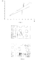
- Fig. 1 shows two lines 11, 13 obtained by fitting, by the method of least squares, data from the experimental results for dielectric breakdown potentials (in kV) measured in composite parts of different thicknesses (in micrometres) on which primer Z12.129 was applied, using the aforementioned equipment.
- Line 11 relates to results obtained a month after application of the paint and line 12 relates to results obtained 8 months after application of the paint. It can be seen that ageing of the paint alters its dielectric resistance and consequently it is necessary to take account of the possible margin of error.
- This test specimen contains several separate zones:
- zones A the potential was applied gradually up to the maximum potential without jumping of an electric arc on the glass fibre.
- the electrode was applied in zones C, verifying that electric arcs were not produced.
- the electrode was passed over zone D. Numerous electric arcs were produced, but not in the zones adjacent to where the glass fibre was maintained.
- said potential was also applied in the openings, where a protective layer of glass fibre has been placed.
- the result was that the glass fibre withstood said electric potential, but not the edges, where jumping of the electric arc occurred.
Landscapes
- Chemical & Material Sciences (AREA)
- Chemical Kinetics & Catalysis (AREA)
- Electrochemistry (AREA)
- Physics & Mathematics (AREA)
- Health & Medical Sciences (AREA)
- Life Sciences & Earth Sciences (AREA)
- Analytical Chemistry (AREA)
- Biochemistry (AREA)
- General Health & Medical Sciences (AREA)
- General Physics & Mathematics (AREA)
- Immunology (AREA)
- Pathology (AREA)
- Investigating Or Analyzing Materials By The Use Of Electric Means (AREA)
- Application Of Or Painting With Fluid Materials (AREA)
Abstract
Description
- The invention relates to the field of manufacture of composite parts, i.e. parts manufactured from a composite material made up of a discontinuous fibre reinforcement and a continuous matrix of thermosetting resin and, more particularly, to a method of quality control of said parts and especially of those used in the aviation industry.
- The intensive introduction of advanced composites or composite materials in the primary structures of aircraft has become one of the priorities in the design and manufacture of a new generation of aircraft owing to the possibilities they provide for their structural optimization.
- Without aiming to be exhaustive, the advantages of composites can be specified in three fundamental aspects:
- Their high specific strength relative to metallic materials which is reflected in an advantageous strength/weight ratio.
- Their excellent behaviour under fatigue loading.
- The possibilities of structural optimization provided by the anisotropy of the material and the possibility of combining fibres with different orientations, permitting the design of elements with various mechanical properties, adapted to varying requirements in terms of applied loads.
- One of the main advantages from the introduction of composites is the cost saving in assembly operations on account of the high degree of integration of structural elements that it permits. However, this high degree of integration demands adequate quality control.
- One of the requirements that arises in the quality control of composite parts used in particular in the aviation industry is the detection of the existence of insulating materials in specific localizations of the parts when these materials are not visible because they are covered by paint or any other non-conductive organic coating.
- In the prior art, destructive methods are used for this, such as abrasive methods for removing the organic coating and some of the non-conductive material to permit visual detection of the presence of said insulating materials.
- In this specific aspect, as in many others, industry demands non-destructive methods, and the present invention is geared to meeting this demand.
- The following terminology will be used in the description of the invention:
- Part: Structural element to which the non-destructive method according to the present invention is applied, such as a structural element of an aircraft.
- Conductive composite: The basic material used for the manufacture of the part, such as a carbon fibre composite.
- Non-conductive material: Material used in the manufacture of the part to provide it with electrically insulating zones in some very precise localizations and of small combined dimension relative to the overall dimension of the whole part. An example of non-conductive material is a glass fibre composite.
- Organic coating: protective layer applied to the part, after manufacture, such as a layer of paint.
- One aim of the present invention is to provide a non-destructive method for detecting non-conductive materials in specific zones of parts made of a conductive composite, when these non-conductive materials are not visible because they are covered by a non-conductive organic coating.
- Another aim of the present invention is to provide a method of quality control in the manufacture of parts from a conductive composite when the existence of electrically insulating zones is required in precise localizations of the part.
- Another aim of the present invention is to provide a method capable of distinguishing between conductive composites and non-conductive materials and, in particular, capable of locating actual areas of non-conductive materials on conductive composites.
- These and other aims are achieved with a non-destructive method for detecting zones with non-conductive materials in a part made of a conductive composite provided with an organic coating, that comprises the following stages:
- a) Provide a device for applying an electric potential to said part.
- b) Determine the dielectric breakdown potential Pr corresponding to the thickness of the coating.
- c) Apply said dielectric breakdown potential Pr with said device to the part for the purpose of identifying those zones that have non-conductive materials when dielectric breakdown does not occur in them.
- Other characteristics and advantages of the present invention will become clear from the following detailed description of an application illustrating its object, referring to the accompanying drawings.
-
-
Fig. 1 is a graph showing the variation in dielectric breakdown potential of a given coating as a function of its thickness. -
Fig. 2 shows schematically a test specimen used for testing the method according to the present invention. - The method according to the present invention uses a technique based on the application of a potential and observation of the dielectric breakdown of the air or of a coating, with known uses for measuring thicknesses or detecting defects in organic coatings on metallic substrates and, in particular, for detecting defects in paint applied to metallic substrates, especially paint on pipes.
- Now, as will be shown below, the method according to the present invention focuses on solving a problem very different from those that arise in the known methods: detection of the presence of a non-conductive material (such as a glass fibre composite), hidden under another different non-conductive material (the coating on the part to which the method is applied) when both are on a third conductive material (the basic component of the part to which the method is applied, typically a carbon fibre composite).
- For application of the method, equipment is used that consists of a direct current source capable of supplying voltages in a predetermined range such as the Compact DC15 detector made by PCWI Technology Pty Ltd which has a sampling electrode formed from a brush of metal wires which are passed over the surface of the part to be tested.
- A fundamental step in the method according to the invention is previous determination of the voltage to apply, i.e. the voltage that produces dielectric breakdown in the coating. When this voltage is applied in a zone in which there is glass fibre or some other non-conductive material underneath the coating, dielectric breakdown will not occur, and consequently an electric arc will not be observed. Accordingly, absence of an electric arc identifies the presence of non-conductive material.
- It was demonstrated in experiments that the dielectric breakdown potential Pr for a given coating is a linear function of its thickness E. In this connection,
Fig. 1 shows twolines 11, 13 obtained by fitting, by the method of least squares, data from the experimental results for dielectric breakdown potentials (in kV) measured in composite parts of different thicknesses (in micrometres) on which primer Z12.129 was applied, using the aforementioned equipment. Line 11 relates to results obtained a month after application of the paint and line 12 relates to results obtained 8 months after application of the paint. It can be seen that ageing of the paint alters its dielectric resistance and consequently it is necessary to take account of the possible margin of error. - In the following we describe a test carried out on the composite test specimen shown schematically in
Fig. 2 with the aforementioned equipment, the results of which confirm the effectiveness of the method of the present invention. Primer Z12.129 was used as the coating. - This test specimen contains several separate zones:
- Zone A: Zone with glass fibre but without coating (delimiting its boundary with insulating tape).
- Zone B: Zone without glass fibre but with coating.
- Zone C: Zone with glass fibre and with coating.
- Zone D: Zone in which glass fibre had been removed by sanding before priming.
- In zones A, the potential was applied gradually up to the maximum potential without jumping of an electric arc on the glass fibre.
- Next, on a zone B, the voltage was increased gradually until dielectric breakdown of the coating was produced, which occurred with a voltage of 4.5 kV.
- Having fixed this potential as reference of the breakdown potential Pr for the thickness E of the coating on the test specimen, the electrode was applied in zones C, verifying that electric arcs were not produced.
- Then, with this potential of 4.5 kV, the electrode was passed over zone D. Numerous electric arcs were produced, but not in the zones adjacent to where the glass fibre was maintained.
- Moreover, said potential was also applied in the openings, where a protective layer of glass fibre has been placed. The result was that the glass fibre withstood said electric potential, but not the edges, where jumping of the electric arc occurred.
- Modifications that are within the scope defined by the following claims can be made to the preferred embodiment that we have just described.
Claims (5)
- Non-destructive method for detecting zones with non-conductive materials in a part made of a conductive composite provided with an organic coating, characterized in that it comprises the following stages:a) providing a device for applying an electric potential on the surface of said part;b) determining the dielectric breakdown potential Pr corresponding to thickness E of the coating;c) applying said dielectric breakdown potential Pr with said device to the part for the purpose of identifying those zones that have non-conductive materials when dielectric breakdown does not occur in them.
- Method according to Claim 1, characterized in that said dielectric breakdown potential Pr is obtained by applying, for each specific coating, a function that depends on the thickness E of the coating, established on the basis of data obtained in tests.
- Method according to either of Claims 1 and 2, characterized in that said conductive composite is a composite whose reinforcing fibres are carbon fibres.
- Method according to any one of Claims 1-3, characterized in that said non-conductive material is a material that includes glass fibres.
- Method according to any one of Claims 1-4, characterized in that said part is a structural element of an aircraft.
Applications Claiming Priority (2)
| Application Number | Priority Date | Filing Date | Title |
|---|---|---|---|
| ES200801523A ES2340457B1 (en) | 2008-05-23 | 2008-05-23 | NON-DESTRUCTIVE METHOD FOR DETECTION OF ZONES WITH NON-CONDUCTING MATERIALS IN A COMPOSITE PIECE. |
| PCT/ES2009/070175 WO2009141483A1 (en) | 2008-05-23 | 2009-05-21 | Non-destructive method for the detection of zones with non-conductive materials in a composite part |
Publications (2)
| Publication Number | Publication Date |
|---|---|
| EP2293057A1 true EP2293057A1 (en) | 2011-03-09 |
| EP2293057B1 EP2293057B1 (en) | 2011-11-09 |
Family
ID=41212203
Family Applications (1)
| Application Number | Title | Priority Date | Filing Date |
|---|---|---|---|
| EP09749967A Not-in-force EP2293057B1 (en) | 2008-05-23 | 2009-05-21 | Non-destructive method for the detection of zones with non-conductive materials in a composite part |
Country Status (8)
| Country | Link |
|---|---|
| US (1) | US7893698B2 (en) |
| EP (1) | EP2293057B1 (en) |
| CN (1) | CN102124325B (en) |
| AT (1) | ATE533047T1 (en) |
| BR (1) | BRPI0915528A2 (en) |
| CA (1) | CA2725025C (en) |
| ES (2) | ES2340457B1 (en) |
| WO (1) | WO2009141483A1 (en) |
Families Citing this family (3)
| Publication number | Priority date | Publication date | Assignee | Title |
|---|---|---|---|---|
| RU169885U1 (en) * | 2016-06-14 | 2017-04-05 | Российская Федерация, от имени которой выступает Министерство промышленности и торговли Российской Федерации (Минпромторг России) | A device for automatically controlling the volumetric electrical resistivity of carbon fiber during its production |
| CN107782235A (en) * | 2017-10-26 | 2018-03-09 | 内蒙古航天红峡化工有限公司 | A kind of measuring method of carbon fiber storepipe face coat thickness |
| FR3122498B1 (en) * | 2021-04-29 | 2023-06-09 | Epsilon Composite | DISCRIMINANT CONTROL METHOD OF A MULTI-MATERIAL COMPOSITE ASSEMBLY |
Family Cites Families (7)
| Publication number | Priority date | Publication date | Assignee | Title |
|---|---|---|---|---|
| JPS58105057A (en) * | 1981-12-17 | 1983-06-22 | Hitachi Ltd | Flitting voltage measuring apparatus |
| JP3456544B2 (en) * | 1993-11-19 | 2003-10-14 | 出光興産株式会社 | Styrene resin composition |
| JPH0862229A (en) * | 1994-08-22 | 1996-03-08 | Ryoden Semiconductor Syst Eng Kk | Thin film quality measuring device, thin film quality measuring method, and semiconductor device manufacturing method |
| US6284373B1 (en) * | 1999-09-10 | 2001-09-04 | Lexmark International, Inc. | Electrostatic fuser rolls and belts |
| JP3940311B2 (en) * | 2002-04-15 | 2007-07-04 | ジョーベン電機株式会社 | Pinhole inspection method for insulation coating |
| US6967499B1 (en) * | 2004-06-21 | 2005-11-22 | Texas Instruments Incorporated | Dual ramp rate dielectric breakdown testing methodology |
| CN101017153A (en) * | 2006-03-13 | 2007-08-15 | 信息产业部电子第五研究所 | Method for estimating and monitoring dielectric film quality and reliability |
-
2008
- 2008-05-23 ES ES200801523A patent/ES2340457B1/en not_active Expired - Fee Related
- 2008-07-30 US US12/182,373 patent/US7893698B2/en not_active Expired - Fee Related
-
2009
- 2009-05-21 CA CA2725025A patent/CA2725025C/en not_active Expired - Fee Related
- 2009-05-21 AT AT09749967T patent/ATE533047T1/en active
- 2009-05-21 ES ES09749967T patent/ES2381618T3/en active Active
- 2009-05-21 WO PCT/ES2009/070175 patent/WO2009141483A1/en not_active Ceased
- 2009-05-21 EP EP09749967A patent/EP2293057B1/en not_active Not-in-force
- 2009-05-21 CN CN200980118778.XA patent/CN102124325B/en not_active Expired - Fee Related
- 2009-05-21 BR BRPI0915528A patent/BRPI0915528A2/en not_active IP Right Cessation
Non-Patent Citations (1)
| Title |
|---|
| See references of WO2009141483A1 * |
Also Published As
| Publication number | Publication date |
|---|---|
| CN102124325B (en) | 2014-05-21 |
| BRPI0915528A2 (en) | 2016-01-26 |
| ATE533047T1 (en) | 2011-11-15 |
| US20090289642A1 (en) | 2009-11-26 |
| ES2340457B1 (en) | 2011-05-26 |
| ES2381618T3 (en) | 2012-05-30 |
| EP2293057B1 (en) | 2011-11-09 |
| ES2340457A1 (en) | 2010-06-02 |
| CA2725025A1 (en) | 2009-11-26 |
| CA2725025C (en) | 2016-10-18 |
| WO2009141483A1 (en) | 2009-11-26 |
| US7893698B2 (en) | 2011-02-22 |
| CN102124325A (en) | 2011-07-13 |
Similar Documents
| Publication | Publication Date | Title |
|---|---|---|
| Liu et al. | Study of the failure mechanism of an epoxy coating system under high hydrostatic pressure | |
| Razin et al. | Detecting and estimating the extent of automotive coating delamination and damage indexes after stone chipping using electrochemical impedance spectroscopy | |
| CA2725025C (en) | Non-destructive method for detecting zones with non-conductive materials in a composite part | |
| Pissolato Filho et al. | The effects of lightning currents in aircraft cfc structures | |
| CN104833870A (en) | Determination of anisotropic conduction characteristics | |
| US10989680B2 (en) | Systems and methods for assessing the quality of adhesive bonds | |
| Tordonato et al. | Adhesion Testing, How Much Is Sufficient? | |
| Walker et al. | Why Voltage Matters for High Voltage Holiday Testing on Steel | |
| Walker | Changes to Holiday Testing Standards and the Risks to Your Coating Projects | |
| Bernhardt et al. | Microstructural and chemical investigation of dielectric breakdown areas in engineering plastics | |
| Huelsbusch et al. | Damage detection and fatigue strength estimation of carbon fibre reinforced polymers (CFRP) using combined electrical and high-frequency impulse measurements | |
| Gamboa et al. | Hydrothermal ageing of X65 steel specimens coated with 100% solids epoxy | |
| Rodiсhev et al. | Comparative analysis of methods for studying the adhesion of antifriction coatings for automotive friction units | |
| Attar et al. | Investigation on the effect of various surface preparations on corrosion performance of powder coated steel by EIS | |
| Banerjee et al. | The role of constraint in the fields of a crack normal to the interface between elastically and plastically mismatched solids | |
| Wels et al. | Dielectric strength and aging performance of polybutylene terephthalate (PBT) under the influence of temperature and humidity | |
| Mercier et al. | Assessment of residual performances of Al–CFRP cocured hybrid samples subjected to galvanic corrosion | |
| El Naggar | Importance of Conducting Holiday Testing on Protective Coatings | |
| Kramer et al. | Effect of Mechanical Stress and Environmental Conditions on Degradation of Aerospace Coatings That Guard Against Atmospheric Corrosion | |
| Latter | Testing and control of coated aluminium and aluminium alloys | |
| Cavallo | Failures from Improper Use of High-Voltage Holiday Detectors | |
| Seneviratne et al. | Seven-Point Bend Test Method to Evaluate Skin-Stringer Post-buckling Separation: Surface Preparations and Moisture Conditioning Effects | |
| Rodichev et al. | The influence of surface preparation methods on the adhesion of film antifriction coatings | |
| Gadallah et al. | Measurement of Residual Stress Distribution at the Weld Root for a U-rib Specimen Using the Contour Method | |
| Francis | Confusion and delusion in coating documentation |
Legal Events
| Date | Code | Title | Description |
|---|---|---|---|
| PUAI | Public reference made under article 153(3) epc to a published international application that has entered the european phase |
Free format text: ORIGINAL CODE: 0009012 |
|
| 17P | Request for examination filed |
Effective date: 20101222 |
|
| AK | Designated contracting states |
Kind code of ref document: A1 Designated state(s): AT BE BG CH CY CZ DE DK EE ES FI FR GB GR HR HU IE IS IT LI LT LU LV MC MK MT NL NO PL PT RO SE SI SK TR |
|
| AX | Request for extension of the european patent |
Extension state: AL BA RS |
|
| GRAP | Despatch of communication of intention to grant a patent |
Free format text: ORIGINAL CODE: EPIDOSNIGR1 |
|
| DAX | Request for extension of the european patent (deleted) | ||
| GRAS | Grant fee paid |
Free format text: ORIGINAL CODE: EPIDOSNIGR3 |
|
| GRAA | (expected) grant |
Free format text: ORIGINAL CODE: 0009210 |
|
| AK | Designated contracting states |
Kind code of ref document: B1 Designated state(s): AT BE BG CH CY CZ DE DK EE ES FI FR GB GR HR HU IE IS IT LI LT LU LV MC MK MT NL NO PL PT RO SE SI SK TR |
|
| REG | Reference to a national code |
Ref country code: GB Ref legal event code: FG4D |
|
| REG | Reference to a national code |
Ref country code: CH Ref legal event code: EP |
|
| REG | Reference to a national code |
Ref country code: IE Ref legal event code: FG4D |
|
| REG | Reference to a national code |
Ref country code: DE Ref legal event code: R096 Ref document number: 602009003634 Country of ref document: DE Effective date: 20120105 |
|
| REG | Reference to a national code |
Ref country code: NL Ref legal event code: VDEP Effective date: 20111109 |
|
| LTIE | Lt: invalidation of european patent or patent extension |
Effective date: 20111109 |
|
| PG25 | Lapsed in a contracting state [announced via postgrant information from national office to epo] |
Ref country code: LT Free format text: LAPSE BECAUSE OF FAILURE TO SUBMIT A TRANSLATION OF THE DESCRIPTION OR TO PAY THE FEE WITHIN THE PRESCRIBED TIME-LIMIT Effective date: 20111109 Ref country code: IS Free format text: LAPSE BECAUSE OF FAILURE TO SUBMIT A TRANSLATION OF THE DESCRIPTION OR TO PAY THE FEE WITHIN THE PRESCRIBED TIME-LIMIT Effective date: 20120309 Ref country code: NO Free format text: LAPSE BECAUSE OF FAILURE TO SUBMIT A TRANSLATION OF THE DESCRIPTION OR TO PAY THE FEE WITHIN THE PRESCRIBED TIME-LIMIT Effective date: 20120209 |
|
| REG | Reference to a national code |
Ref country code: ES Ref legal event code: FG2A Ref document number: 2381618 Country of ref document: ES Kind code of ref document: T3 Effective date: 20120530 |
|
| PG25 | Lapsed in a contracting state [announced via postgrant information from national office to epo] |
Ref country code: PL Free format text: LAPSE BECAUSE OF FAILURE TO SUBMIT A TRANSLATION OF THE DESCRIPTION OR TO PAY THE FEE WITHIN THE PRESCRIBED TIME-LIMIT Effective date: 20111109 Ref country code: NL Free format text: LAPSE BECAUSE OF FAILURE TO SUBMIT A TRANSLATION OF THE DESCRIPTION OR TO PAY THE FEE WITHIN THE PRESCRIBED TIME-LIMIT Effective date: 20111109 Ref country code: PT Free format text: LAPSE BECAUSE OF FAILURE TO SUBMIT A TRANSLATION OF THE DESCRIPTION OR TO PAY THE FEE WITHIN THE PRESCRIBED TIME-LIMIT Effective date: 20120309 Ref country code: HR Free format text: LAPSE BECAUSE OF FAILURE TO SUBMIT A TRANSLATION OF THE DESCRIPTION OR TO PAY THE FEE WITHIN THE PRESCRIBED TIME-LIMIT Effective date: 20111109 Ref country code: LV Free format text: LAPSE BECAUSE OF FAILURE TO SUBMIT A TRANSLATION OF THE DESCRIPTION OR TO PAY THE FEE WITHIN THE PRESCRIBED TIME-LIMIT Effective date: 20111109 Ref country code: GR Free format text: LAPSE BECAUSE OF FAILURE TO SUBMIT A TRANSLATION OF THE DESCRIPTION OR TO PAY THE FEE WITHIN THE PRESCRIBED TIME-LIMIT Effective date: 20120210 Ref country code: SI Free format text: LAPSE BECAUSE OF FAILURE TO SUBMIT A TRANSLATION OF THE DESCRIPTION OR TO PAY THE FEE WITHIN THE PRESCRIBED TIME-LIMIT Effective date: 20111109 Ref country code: SE Free format text: LAPSE BECAUSE OF FAILURE TO SUBMIT A TRANSLATION OF THE DESCRIPTION OR TO PAY THE FEE WITHIN THE PRESCRIBED TIME-LIMIT Effective date: 20111109 Ref country code: BE Free format text: LAPSE BECAUSE OF FAILURE TO SUBMIT A TRANSLATION OF THE DESCRIPTION OR TO PAY THE FEE WITHIN THE PRESCRIBED TIME-LIMIT Effective date: 20111109 |
|
| PG25 | Lapsed in a contracting state [announced via postgrant information from national office to epo] |
Ref country code: CY Free format text: LAPSE BECAUSE OF FAILURE TO SUBMIT A TRANSLATION OF THE DESCRIPTION OR TO PAY THE FEE WITHIN THE PRESCRIBED TIME-LIMIT Effective date: 20111109 |
|
| PG25 | Lapsed in a contracting state [announced via postgrant information from national office to epo] |
Ref country code: EE Free format text: LAPSE BECAUSE OF FAILURE TO SUBMIT A TRANSLATION OF THE DESCRIPTION OR TO PAY THE FEE WITHIN THE PRESCRIBED TIME-LIMIT Effective date: 20111109 Ref country code: DK Free format text: LAPSE BECAUSE OF FAILURE TO SUBMIT A TRANSLATION OF THE DESCRIPTION OR TO PAY THE FEE WITHIN THE PRESCRIBED TIME-LIMIT Effective date: 20111109 Ref country code: BG Free format text: LAPSE BECAUSE OF FAILURE TO SUBMIT A TRANSLATION OF THE DESCRIPTION OR TO PAY THE FEE WITHIN THE PRESCRIBED TIME-LIMIT Effective date: 20120209 Ref country code: CZ Free format text: LAPSE BECAUSE OF FAILURE TO SUBMIT A TRANSLATION OF THE DESCRIPTION OR TO PAY THE FEE WITHIN THE PRESCRIBED TIME-LIMIT Effective date: 20111109 Ref country code: SK Free format text: LAPSE BECAUSE OF FAILURE TO SUBMIT A TRANSLATION OF THE DESCRIPTION OR TO PAY THE FEE WITHIN THE PRESCRIBED TIME-LIMIT Effective date: 20111109 |
|
| PG25 | Lapsed in a contracting state [announced via postgrant information from national office to epo] |
Ref country code: RO Free format text: LAPSE BECAUSE OF FAILURE TO SUBMIT A TRANSLATION OF THE DESCRIPTION OR TO PAY THE FEE WITHIN THE PRESCRIBED TIME-LIMIT Effective date: 20111109 |
|
| PLBE | No opposition filed within time limit |
Free format text: ORIGINAL CODE: 0009261 |
|
| STAA | Information on the status of an ep patent application or granted ep patent |
Free format text: STATUS: NO OPPOSITION FILED WITHIN TIME LIMIT |
|
| REG | Reference to a national code |
Ref country code: AT Ref legal event code: MK05 Ref document number: 533047 Country of ref document: AT Kind code of ref document: T Effective date: 20111109 |
|
| 26N | No opposition filed |
Effective date: 20120810 |
|
| REG | Reference to a national code |
Ref country code: DE Ref legal event code: R097 Ref document number: 602009003634 Country of ref document: DE Effective date: 20120810 |
|
| PG25 | Lapsed in a contracting state [announced via postgrant information from national office to epo] |
Ref country code: MC Free format text: LAPSE BECAUSE OF NON-PAYMENT OF DUE FEES Effective date: 20120531 |
|
| PG25 | Lapsed in a contracting state [announced via postgrant information from national office to epo] |
Ref country code: AT Free format text: LAPSE BECAUSE OF FAILURE TO SUBMIT A TRANSLATION OF THE DESCRIPTION OR TO PAY THE FEE WITHIN THE PRESCRIBED TIME-LIMIT Effective date: 20111109 |
|
| REG | Reference to a national code |
Ref country code: IE Ref legal event code: MM4A |
|
| PG25 | Lapsed in a contracting state [announced via postgrant information from national office to epo] |
Ref country code: MK Free format text: LAPSE BECAUSE OF FAILURE TO SUBMIT A TRANSLATION OF THE DESCRIPTION OR TO PAY THE FEE WITHIN THE PRESCRIBED TIME-LIMIT Effective date: 20111109 |
|
| PG25 | Lapsed in a contracting state [announced via postgrant information from national office to epo] |
Ref country code: IE Free format text: LAPSE BECAUSE OF NON-PAYMENT OF DUE FEES Effective date: 20120521 |
|
| PG25 | Lapsed in a contracting state [announced via postgrant information from national office to epo] |
Ref country code: FI Free format text: LAPSE BECAUSE OF FAILURE TO SUBMIT A TRANSLATION OF THE DESCRIPTION OR TO PAY THE FEE WITHIN THE PRESCRIBED TIME-LIMIT Effective date: 20111109 |
|
| PG25 | Lapsed in a contracting state [announced via postgrant information from national office to epo] |
Ref country code: MT Free format text: LAPSE BECAUSE OF FAILURE TO SUBMIT A TRANSLATION OF THE DESCRIPTION OR TO PAY THE FEE WITHIN THE PRESCRIBED TIME-LIMIT Effective date: 20111109 |
|
| REG | Reference to a national code |
Ref country code: CH Ref legal event code: PL |
|
| PG25 | Lapsed in a contracting state [announced via postgrant information from national office to epo] |
Ref country code: CH Free format text: LAPSE BECAUSE OF NON-PAYMENT OF DUE FEES Effective date: 20130531 Ref country code: LI Free format text: LAPSE BECAUSE OF NON-PAYMENT OF DUE FEES Effective date: 20130531 |
|
| PG25 | Lapsed in a contracting state [announced via postgrant information from national office to epo] |
Ref country code: TR Free format text: LAPSE BECAUSE OF FAILURE TO SUBMIT A TRANSLATION OF THE DESCRIPTION OR TO PAY THE FEE WITHIN THE PRESCRIBED TIME-LIMIT Effective date: 20111109 |
|
| PG25 | Lapsed in a contracting state [announced via postgrant information from national office to epo] |
Ref country code: LU Free format text: LAPSE BECAUSE OF NON-PAYMENT OF DUE FEES Effective date: 20120521 |
|
| PG25 | Lapsed in a contracting state [announced via postgrant information from national office to epo] |
Ref country code: HU Free format text: LAPSE BECAUSE OF FAILURE TO SUBMIT A TRANSLATION OF THE DESCRIPTION OR TO PAY THE FEE WITHIN THE PRESCRIBED TIME-LIMIT Effective date: 20090521 |
|
| REG | Reference to a national code |
Ref country code: FR Ref legal event code: PLFP Year of fee payment: 8 |
|
| REG | Reference to a national code |
Ref country code: FR Ref legal event code: PLFP Year of fee payment: 9 |
|
| REG | Reference to a national code |
Ref country code: FR Ref legal event code: PLFP Year of fee payment: 10 |
|
| PGFP | Annual fee paid to national office [announced via postgrant information from national office to epo] |
Ref country code: ES Payment date: 20190621 Year of fee payment: 11 |
|
| PGFP | Annual fee paid to national office [announced via postgrant information from national office to epo] |
Ref country code: GB Payment date: 20190521 Year of fee payment: 11 |
|
| PGFP | Annual fee paid to national office [announced via postgrant information from national office to epo] |
Ref country code: DE Payment date: 20200520 Year of fee payment: 12 Ref country code: FR Payment date: 20200522 Year of fee payment: 12 |
|
| PGFP | Annual fee paid to national office [announced via postgrant information from national office to epo] |
Ref country code: IT Payment date: 20200528 Year of fee payment: 12 |
|
| GBPC | Gb: european patent ceased through non-payment of renewal fee |
Effective date: 20200521 |
|
| PG25 | Lapsed in a contracting state [announced via postgrant information from national office to epo] |
Ref country code: GB Free format text: LAPSE BECAUSE OF NON-PAYMENT OF DUE FEES Effective date: 20200521 |
|
| REG | Reference to a national code |
Ref country code: ES Ref legal event code: FD2A Effective date: 20211004 |
|
| PG25 | Lapsed in a contracting state [announced via postgrant information from national office to epo] |
Ref country code: ES Free format text: LAPSE BECAUSE OF NON-PAYMENT OF DUE FEES Effective date: 20200522 |
|
| REG | Reference to a national code |
Ref country code: DE Ref legal event code: R119 Ref document number: 602009003634 Country of ref document: DE |
|
| PG25 | Lapsed in a contracting state [announced via postgrant information from national office to epo] |
Ref country code: DE Free format text: LAPSE BECAUSE OF NON-PAYMENT OF DUE FEES Effective date: 20211201 |
|
| PG25 | Lapsed in a contracting state [announced via postgrant information from national office to epo] |
Ref country code: FR Free format text: LAPSE BECAUSE OF NON-PAYMENT OF DUE FEES Effective date: 20210531 |
|
| PG25 | Lapsed in a contracting state [announced via postgrant information from national office to epo] |
Ref country code: IT Free format text: LAPSE BECAUSE OF NON-PAYMENT OF DUE FEES Effective date: 20200521 |
|
| PG25 | Lapsed in a contracting state [announced via postgrant information from national office to epo] |
Ref country code: IT Free format text: LAPSE BECAUSE OF NON-PAYMENT OF DUE FEES Effective date: 20210521 |