EP2293041A2 - A test specimen for testing through-thickness properties - Google Patents
A test specimen for testing through-thickness properties Download PDFInfo
- Publication number
- EP2293041A2 EP2293041A2 EP10172598A EP10172598A EP2293041A2 EP 2293041 A2 EP2293041 A2 EP 2293041A2 EP 10172598 A EP10172598 A EP 10172598A EP 10172598 A EP10172598 A EP 10172598A EP 2293041 A2 EP2293041 A2 EP 2293041A2
- Authority
- EP
- European Patent Office
- Prior art keywords
- loading
- test specimen
- test
- portions
- axis
- Prior art date
- Legal status (The legal status is an assumption and is not a legal conclusion. Google has not performed a legal analysis and makes no representation as to the accuracy of the status listed.)
- Granted
Links
- 238000012360 testing method Methods 0.000 title claims abstract description 62
- 239000011208 reinforced composite material Substances 0.000 claims abstract description 7
- 239000002131 composite material Substances 0.000 claims description 26
- 238000004519 manufacturing process Methods 0.000 claims description 5
- 238000000034 method Methods 0.000 claims description 5
- 238000010998 test method Methods 0.000 claims description 4
- 238000003754 machining Methods 0.000 claims description 3
- 230000007704 transition Effects 0.000 claims description 3
- 239000002184 metal Substances 0.000 claims description 2
- 239000000853 adhesive Substances 0.000 description 10
- 230000001070 adhesive effect Effects 0.000 description 10
- 229910000831 Steel Inorganic materials 0.000 description 4
- 239000010959 steel Substances 0.000 description 4
- 229920002430 Fibre-reinforced plastic Polymers 0.000 description 3
- 239000011151 fibre-reinforced plastic Substances 0.000 description 3
- 239000000463 material Substances 0.000 description 3
- 230000002787 reinforcement Effects 0.000 description 3
- 230000003014 reinforcing effect Effects 0.000 description 3
- 230000000704 physical effect Effects 0.000 description 2
- 239000011165 3D composite Substances 0.000 description 1
- 238000005452 bending Methods 0.000 description 1
- 230000005540 biological transmission Effects 0.000 description 1
- 230000015572 biosynthetic process Effects 0.000 description 1
- 238000012512 characterization method Methods 0.000 description 1
- 230000006835 compression Effects 0.000 description 1
- 238000007906 compression Methods 0.000 description 1
- 239000000470 constituent Substances 0.000 description 1
- 239000000835 fiber Substances 0.000 description 1
- 239000011159 matrix material Substances 0.000 description 1
- 230000004048 modification Effects 0.000 description 1
- 238000012986 modification Methods 0.000 description 1
- 238000010526 radical polymerization reaction Methods 0.000 description 1
- HBMJWWWQQXIZIP-UHFFFAOYSA-N silicon carbide Chemical compound [Si+]#[C-] HBMJWWWQQXIZIP-UHFFFAOYSA-N 0.000 description 1
- 229910010271 silicon carbide Inorganic materials 0.000 description 1
- 239000007858 starting material Substances 0.000 description 1
Images


Classifications
-
- G—PHYSICS
- G01—MEASURING; TESTING
- G01N—INVESTIGATING OR ANALYSING MATERIALS BY DETERMINING THEIR CHEMICAL OR PHYSICAL PROPERTIES
- G01N3/00—Investigating strength properties of solid materials by application of mechanical stress
- G01N3/02—Details
-
- G—PHYSICS
- G01—MEASURING; TESTING
- G01N—INVESTIGATING OR ANALYSING MATERIALS BY DETERMINING THEIR CHEMICAL OR PHYSICAL PROPERTIES
- G01N2203/00—Investigating strength properties of solid materials by application of mechanical stress
- G01N2203/02—Details not specific for a particular testing method
- G01N2203/026—Specifications of the specimen
- G01N2203/0262—Shape of the specimen
- G01N2203/0272—Cruciform specimens
-
- G—PHYSICS
- G01—MEASURING; TESTING
- G01N—INVESTIGATING OR ANALYSING MATERIALS BY DETERMINING THEIR CHEMICAL OR PHYSICAL PROPERTIES
- G01N2203/00—Investigating strength properties of solid materials by application of mechanical stress
- G01N2203/02—Details not specific for a particular testing method
- G01N2203/026—Specifications of the specimen
- G01N2203/0298—Manufacturing or preparing specimens
-
- Y—GENERAL TAGGING OF NEW TECHNOLOGICAL DEVELOPMENTS; GENERAL TAGGING OF CROSS-SECTIONAL TECHNOLOGIES SPANNING OVER SEVERAL SECTIONS OF THE IPC; TECHNICAL SUBJECTS COVERED BY FORMER USPC CROSS-REFERENCE ART COLLECTIONS [XRACs] AND DIGESTS
- Y10—TECHNICAL SUBJECTS COVERED BY FORMER USPC
- Y10T—TECHNICAL SUBJECTS COVERED BY FORMER US CLASSIFICATION
- Y10T29/00—Metal working
- Y10T29/49—Method of mechanical manufacture
- Y10T29/49995—Shaping one-piece blank by removing material
Definitions
- the present invention relates to a test specimen, and a method of testing a specimen - in particular, a composite test specimen - and a method of manufacturing such a specimen.
- Fiber-Reinforced-Polymer (FRP) composites comprising fibres embedded in a polymeric matrix system, are commonly used for many engineering applications. They can be classified into uni-directional (UD), two-dimensional (2D) and three-dimensional (3D) composites. Composites can offer certain advantages over conventional materials such as a high strength to weight ratio. However, physical properties of FRPs tend not to be isotropic. It is therefore necessary to be able to characterise the various physical properties of fibre-reinforced composites in a number of directions.
- FRP Fibre-Reinforced-Polymer
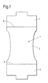
- Figure 1 shows a previously considered method of testing the tensile strength of UD and 2D FRP plates in the through-thickness direction.
- a test specimen 1 is provided that has a gauge section 2 having a reduced cross-sectional area.
- Metal end caps 3 are bonded to the ends of the specimen using an adhesive 4.
- a tensile force is then applied between the end caps 3 and this force is transmitted to the specimen through the adhesive bond 4.
- the adhesive bond 4 may be weaker then the composite. It is therefore necessary to produce a test specimen 1 that has a gauge section 2 having a cross-sectional area that is sufficiently smaller than the area of the adhesive bonds so as to ensure that the gauge section 2 fails in tension, not the adhesive bond 4.
- Embodiments of the present invention aim to address at least some of the above problems.
- test specimen for testing the through-thickness properties of a fibre-reinforced composite material, a method of manufacturing such a specimen, and a method of testing such a specimen, as set out in the claims.
- the invention may comprise any combination of the features and/or limitations referred to herein, except combinations of such features as are mutually exclusive.
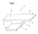
- a test specimen 6 comprises a generally cruciform, single piece of fibre-reinforced composite material.
- the piece of composite material comprises a first upper loading portion 10, a second lower loading portion 20 and a test gauge portion 30 that are integral.
- the first and second loading portions 10, 20 are in the form of elongate rectangular planar portions.
- the loading portions 10, 20 are planar and parallel to one another and are orientated perpendicular to one another such that they overlap at a mid-point.
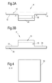
- the test gauge portion 30 has a square cross-section in a plane parallel to the loading portions 10, 20, that has dimensions equal to the width of the loading portions 10, 20.
- the transition between the loading portions 10, 20 and the test gauge portion 30 is filleted in order to reduce stress concentrations.
- the first and second loading portions 10, 20 extend either side of the gauge portion 30 along first and second perpendicular axes respectively. This provides first and second loading surfaces 12, 14 on the first loading portion 10 and third and fourth loading surfaces 22, 24 on the second loading portion 20.
- the test specimen is manufactured from a small thin rectangular composite plate 40.
- two prismatic side pieces 42, 44 are machined from the top surface of the plate 40, either side of the plate 40. These pieces 42, 44 are substantially rectangular and have a thickness that is less than that of the plate 40. This means that a lower loading portion 20 is formed which extends either side of a central portion 46 ( Figure 5C ).
- two prismatic side pieces 48, 50 are then machined from the lower surface of the plate 40, either side of the plate 40. These pieces 48, 50 are of a similar dimension to the prismatic side pieces 42, 44 but extend in a direction perpendicular to the prismatic side pieces 42, 44.
- the above steps result in the formation of a cruciform test specimen 6 as described above having first and second loading portions 10, 20 and a test gauge portion 30.
- Any suitable machining method can be used such as grinding using a silicon carbide wheel.
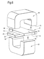
- Figure 6 shows an apparatus for testing the tensile strength of the composite test specimen 6.
- a lower U-shaped rig 60 and an upper U-shaped rig 66 are used to apply a tensile force to the test gauge portion 30 of the specimen 6.
- the lower U-shaped rig 60 applies an upwards force to the first upper loading portion 10 and the upper U-shaped rig 66 is used to apply a downwards force to the second lower loading portion 20.
- the end faces 62, 64 of the lower rig 60 apply equal forces to the first and second loading surfaces 12, 14 of the first upper loading portion 10 and the end faces 68, 70 of the upper rig 66 apply equal forces to the loading surfaces 22, 24 of the second lower loading portion 20.
- These forces can be achieved by applying a compressive force between the upper and lower rigs 60, 66, which generates a tensile stress state in the test gauge portion 30.
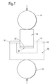
- Figure 7 shows schematically an experimental assembly using the apparatus of Figure 5 .
- Steel balls 72, 74 are placed above and below the rigs 60, 66 and a compressive force is applied between them.
- the steel balls 72, 74 ensure that the force is applied perpendicular to the face of the upper and lower rigs 60, 66.
- the composite can then be tested to failure to determine the tensile strength of the composite.
- Figure 8 shows an embodiment in which steel beams (or plates) 76, 78 are adhesively bonded to the upper surface of the first upper loading portion 10 and to the lower surface of the second lower loading portion 20. This reduces the tendency of the loading portions 10, 20 to bend.
- the incidence of stress concentrations, in the region of the transition from the loading portions 10, 20 to the gauge portion 30, is reduced as compared to the above-described embodiment.
- the disadvantage of such bending and stress concentrations is that they can give rise to peeling in the loading portions of the test specimen, so that the test result will not accurately reflect the through-thickness properties of the test specimen.
- test specimen 6 When the test specimen 6 is loaded in the through-thickness direction in tension, it fails in the gauge section 30.
- the tensile force is transmitted into the gauge section 30 through the crossing of the loading portions 10, 20 without using an adhesive bond, therefore preserving the reinforcing effect of the through-thickness reinforcement.
- test specimen 6 can be tested to tensile failure in the through-thickness direction, even if the composite is highly reinforced.
- test specimen 6 can also be produced with ease using the manufacturing technique described above. This requires only a small amount of composite material, so a large number of test specimens can be manufactured from a small amount of starting material.
- test specimen 6 can be easily used with split Hopkinson compression bars; this enables the characterisation of the through-thickness properties of the composite at high strain rates.
Landscapes
- Physics & Mathematics (AREA)
- Health & Medical Sciences (AREA)
- Life Sciences & Earth Sciences (AREA)
- Chemical & Material Sciences (AREA)
- Analytical Chemistry (AREA)
- Biochemistry (AREA)
- General Health & Medical Sciences (AREA)
- General Physics & Mathematics (AREA)
- Immunology (AREA)
- Pathology (AREA)
- Investigating Strength Of Materials By Application Of Mechanical Stress (AREA)
- Sampling And Sample Adjustment (AREA)
Abstract
Description
- The present invention relates to a test specimen, and a method of testing a specimen - in particular, a composite test specimen - and a method of manufacturing such a specimen.
- Composite materials (otherwise known as 'composites') are materials that are made from two or more constituent materials. Fibre-Reinforced-Polymer (FRP) composites, comprising fibres embedded in a polymeric matrix system, are commonly used for many engineering applications. They can be classified into uni-directional (UD), two-dimensional (2D) and three-dimensional (3D) composites. Composites can offer certain advantages over conventional materials such as a high strength to weight ratio. However, physical properties of FRPs tend not to be isotropic. It is therefore necessary to be able to characterise the various physical properties of fibre-reinforced composites in a number of directions.
- Testing the properties of fibre-reinforced composite plates in the through-thickness direction can be especially difficult. This is because composite plates are usually thin which means that it is difficult to transmit the load into the specimen. If the composite is reinforced in the through-thickness direction, as in the case of 3D composites, it becomes even more difficult to test the through-thickness properties because the composite is particularly strong in this direction, and the force needs to be transmitted in a way that allows the 3D reinforcement to maintain its reinforcing effect.
-
Figure 1 shows a previously considered method of testing the tensile strength of UD and 2D FRP plates in the through-thickness direction. A test specimen 1 is provided that has agauge section 2 having a reduced cross-sectional area.Metal end caps 3 are bonded to the ends of the specimen using an adhesive 4. A tensile force is then applied between theend caps 3 and this force is transmitted to the specimen through theadhesive bond 4. However, theadhesive bond 4 may be weaker then the composite. It is therefore necessary to produce a test specimen 1 that has agauge section 2 having a cross-sectional area that is sufficiently smaller than the area of the adhesive bonds so as to ensure that thegauge section 2 fails in tension, not theadhesive bond 4. However, it can be difficult to reduce sufficiently the cross-sectional area of thegauge section 2 because composite plates are usually relatively thin. - This becomes even more problematic if the composite plate is reinforced in the through-thickness direction because it is then even more difficult to produce an
adhesive bond 4 of a sufficient strength such that in tension, thegauge section 2 always fails, and not theadhesive bond 4. Furthermore, force transmission into 3D reinforcing fibre tows oriented in the through-thickness direction using an adhesive bond is impractical, as the typical strength of the 3D reinforcement exceeds the strength of typically available adhesives by an order of magnitude. - Embodiments of the present invention aim to address at least some of the above problems.
- According to the present invention there is provided a test specimen for testing the through-thickness properties of a fibre-reinforced composite material, a method of manufacturing such a specimen, and a method of testing such a specimen, as set out in the claims.
- The invention may comprise any combination of the features and/or limitations referred to herein, except combinations of such features as are mutually exclusive.
- Embodiments of the present invention will now be described, by way of example, with reference to the accompanying drawings, in which:
-
Figure 1 schematically shows a previously considered arrangement for testing a composite plate; -
Figure 2 schematically shows a perspective view of a test specimen according to the present invention; -
Figures 3A and 3B schematically show a front and side view of the test specimen ofFigure 2 ; -
Figure 4 schematically shows the section A-A ofFigure 3 ; -
Figures 5A-E schematically illustrate the steps of manufacturing a test specimen according to the present invention; -
Figure 6 schematically shows a test specimen in a test rig; -
Figure 7 schematically shows an experimental set-up for testing a test specimen according to the present invention; and -
Figure 8 schematically shows a modification of the test specimen ofFigure 1 . - As shown in
Figures 2 and3 atest specimen 6 according to the present invention comprises a generally cruciform, single piece of fibre-reinforced composite material. The piece of composite material comprises a firstupper loading portion 10, a secondlower loading portion 20 and atest gauge portion 30 that are integral. The first andsecond loading portions loading portions loading portions test gauge portion 30. As shown inFigure 4 , thetest gauge portion 30 has a square cross-section in a plane parallel to theloading portions loading portions loading portions test gauge portion 30 is filleted in order to reduce stress concentrations. - The first and
second loading portions gauge portion 30 along first and second perpendicular axes respectively. This provides first andsecond loading surfaces first loading portion 10 and third andfourth loading surfaces second loading portion 20. - With reference to
Figure 5A the test specimen is manufactured from a small thinrectangular composite plate 40. As shown inFigure 5B , twoprismatic side pieces plate 40, either side of theplate 40. Thesepieces plate 40. This means that alower loading portion 20 is formed which extends either side of a central portion 46 (Figure 5C ). As shown inFigure 5D , twoprismatic side pieces plate 40, either side of theplate 40. Thesepieces prismatic side pieces prismatic side pieces Figure 5E , the above steps result in the formation of acruciform test specimen 6 as described above having first andsecond loading portions test gauge portion 30. Any suitable machining method can be used such as grinding using a silicon carbide wheel. -
Figure 6 shows an apparatus for testing the tensile strength of thecomposite test specimen 6. Alower U-shaped rig 60 and anupper U-shaped rig 66 are used to apply a tensile force to thetest gauge portion 30 of thespecimen 6. Thelower U-shaped rig 60 applies an upwards force to the firstupper loading portion 10 and theupper U-shaped rig 66 is used to apply a downwards force to the secondlower loading portion 20. More specifically, the end faces 62, 64 of thelower rig 60 apply equal forces to the first andsecond loading surfaces upper loading portion 10 and the end faces 68, 70 of theupper rig 66 apply equal forces to theloading surfaces lower loading portion 20. These forces can be achieved by applying a compressive force between the upper andlower rigs test gauge portion 30. -
Figure 7 shows schematically an experimental assembly using the apparatus ofFigure 5 .Steel balls rigs steel balls lower rigs -
Figure 8 shows an embodiment in which steel beams (or plates) 76, 78 are adhesively bonded to the upper surface of the firstupper loading portion 10 and to the lower surface of the secondlower loading portion 20. This reduces the tendency of theloading portions specimen 6 is tested using the steel beams of this embodiment, the incidence of stress concentrations, in the region of the transition from theloading portions gauge portion 30, is reduced as compared to the above-described embodiment. The disadvantage of such bending and stress concentrations is that they can give rise to peeling in the loading portions of the test specimen, so that the test result will not accurately reflect the through-thickness properties of the test specimen. - When the
test specimen 6 is loaded in the through-thickness direction in tension, it fails in thegauge section 30. The tensile force is transmitted into thegauge section 30 through the crossing of theloading portions - This means that the
test specimen 6 can be tested to tensile failure in the through-thickness direction, even if the composite is highly reinforced. - The
test specimen 6 can also be produced with ease using the manufacturing technique described above. This requires only a small amount of composite material, so a large number of test specimens can be manufactured from a small amount of starting material. - Furthermore, because a compressive load is used to apply a tensile force to the
gauge section 30, thetest specimen 6 can be easily used with split Hopkinson compression bars; this enables the characterisation of the through-thickness properties of the composite at high strain rates.
Claims (13)
- A test specimen (6) for testing the through-thickness properties of a fibre-reinforced composite material comprising:a single piece of fibre-reinforced composite material comprising:a first loading portion (10) having a first longitudinal axis in a first plane and a second loading portion (20) having a second longitudinal axis in a second plane, wherein the first and second planes are substantially parallel; the first and second axes are oblique; and the first and second loading portions (10, 20) partially overlap to form a test gauge portion (30) that is integral with the first and second loading portions (10, 20); andwherein the first loading portion (10) extends beyond the test gauge portion in opposite directions along the first axis and the second loading portion (20) extends beyond the test gauge portion in opposite directions along the second axis, such that a force can be applied to the test gauge portion (30) through the first and second loading portions (10, 20).
- A test specimen (6) according to claim 1, wherein the fibre-reinforced composite material is a three-dimension reinforced composite material.
- A test specimen (6) according to claim 1 or 2, wherein the test specimen is of a generally cruciform shape.
- A test specimen (6) according to any preceding claim, wherein the first axis is perpendicular to the second axis.
- A test specimen (6) according to any preceding claim, wherein the transition between the first and second loading portions (10, 20) and the test gauge portion (30) is filleted.
- A test specimen (6) according to any preceding claim, wherein a plate (76, 78) is attached to each of the first and second loading portions.
- A test specimen (6) according to claim 6, wherein the plates (76, 78) are metal.
- A test specimen (6) according to claim 6 or 7, wherein the plate (76, 78) is glued to the first and second loading portions (10, 20).
- A method of manufacturing the test specimen (6) according to any of claims 1-5, comprising:machining first and second side portions (42, 44) from a first surface of a fibre-reinforced composite plate (40) along a first axis; andmachining third and fourth side portions (48, 50) off a second surface of the fibre-reinforced composite plate (40) along a second axis that is oblique to the first axis, wherein the second surface is opposed to the first surface.
- A method according to claim 9, wherein the first and second axes are perpendicular.
- A method according to claim 9 or 10, wherein the first, second, third and fourth portions (42, 44, 46, 48) are prismatic.
- A method according to claim 11, wherein the prismatic portions (42, 44, 46, 48) are substantially rectangular.
- A method of testing the test specimen according to any of claims 1-8, comprising:applying a first force to the first loading portion (10) and a second force to the second loading portion (20) so as to transmit a force to the test gauge section (30).
Applications Claiming Priority (1)
| Application Number | Priority Date | Filing Date | Title |
|---|---|---|---|
| GBGB0914365.2A GB0914365D0 (en) | 2009-08-18 | 2009-08-18 | Test speciment and method of manufacturing testing |
Publications (3)
| Publication Number | Publication Date |
|---|---|
| EP2293041A2 true EP2293041A2 (en) | 2011-03-09 |
| EP2293041A3 EP2293041A3 (en) | 2013-01-09 |
| EP2293041B1 EP2293041B1 (en) | 2015-02-18 |
Family
ID=41171508
Family Applications (1)
| Application Number | Title | Priority Date | Filing Date |
|---|---|---|---|
| EP10172598.4A Not-in-force EP2293041B1 (en) | 2009-08-18 | 2010-08-12 | A test specimen for testing through-thickness properties |
Country Status (4)
| Country | Link |
|---|---|
| US (1) | US8650975B2 (en) |
| EP (1) | EP2293041B1 (en) |
| CN (1) | CN102004050B (en) |
| GB (1) | GB0914365D0 (en) |
Cited By (2)
| Publication number | Priority date | Publication date | Assignee | Title |
|---|---|---|---|---|
| CN110779799A (en) * | 2019-11-20 | 2020-02-11 | 青岛滨海学院 | Thermal management composite material tensile test sample and preparation method thereof |
| WO2020087102A1 (en) * | 2018-10-31 | 2020-05-07 | Technische Universität Wien | Method and means for testing the strength of a bonding between two specimen elements |
Families Citing this family (6)
| Publication number | Priority date | Publication date | Assignee | Title |
|---|---|---|---|---|
| CN102252896A (en) * | 2011-04-21 | 2011-11-23 | 西北工业大学 | Test sample with two straight waist-shaped side faces and for testing tension and compression property of composite material laminated thick plate |
| ITSA20120008A1 (en) * | 2012-05-16 | 2012-08-15 | Univ Degli Studi Salerno | DEVICE FOR FRACTURE RESISTANCE TESTING FOR WAY III ON GLUED JOINTS |
| NL2010556C2 (en) * | 2013-04-03 | 2014-10-06 | Onderzoekscentrum Voor Aanwending Van Staal N V | Fatigue testing of a test specimen. |
| USD722900S1 (en) * | 2013-11-04 | 2015-02-24 | King Tester Corporation | Metal hardness tester block having an alphanumeric platted grid |
| CN106153476B (en) * | 2016-08-09 | 2018-09-11 | 宁波中加低碳新技术研究院有限公司 | Timber rolls the test method of modulus of shearing and intensity |
| CN109297811A (en) * | 2018-09-28 | 2019-02-01 | 西北工业大学 | Biaxial bidirectional compression loading device and method thereof |
Family Cites Families (9)
| Publication number | Priority date | Publication date | Assignee | Title |
|---|---|---|---|---|
| JPS58173450A (en) | 1982-04-06 | 1983-10-12 | Taiyo Kogyo Kk | Biaxial tension tester |
| FR2579327B1 (en) | 1985-03-22 | 1987-06-26 | Centre Nat Rech Scient | IMPROVED BIAXIAL TRACTION TEST DEVICE |
| SU1415124A1 (en) | 1986-12-15 | 1988-08-07 | Ленинградский инженерно-строительный институт | Installation for two-axes tension of cross-shaped specimens made of composite materials |
| US4850715A (en) * | 1987-09-01 | 1989-07-25 | Gaffin Norman H | Dual material test specimen |
| US4895027A (en) * | 1988-01-19 | 1990-01-23 | Battelle Development Corporation | Determining plane strain fracture toughness and the J-Integral for solid materials using stress field modified miniature specimens |
| DE3914966C2 (en) * | 1989-05-03 | 1996-01-11 | Inpro Innovations Gmbh | Cross-shaped, flat sample, especially made of sheet metal for a two-axis material test in the area of high elongation |
| EP0660100A3 (en) | 1993-12-10 | 1996-02-21 | Inst Michanikis Ylikon Kai Geo | Specimen design for uniform triaxial tensile stress-strain distribution under high/low temperatures. |
| JP4150383B2 (en) * | 2004-04-13 | 2008-09-17 | 新日本製鐵株式会社 | Fracture prediction apparatus, method, computer program, and computer-readable recording medium for spot welds |
| GB0713047D0 (en) * | 2007-07-06 | 2007-08-15 | Airbus Uk Ltd | Method and apparatus for testing composite materials |
-
2009
- 2009-08-18 GB GBGB0914365.2A patent/GB0914365D0/en not_active Ceased
-
2010
- 2010-08-12 EP EP10172598.4A patent/EP2293041B1/en not_active Not-in-force
- 2010-08-12 US US12/854,963 patent/US8650975B2/en not_active Expired - Fee Related
- 2010-08-18 CN CN201010504134.9A patent/CN102004050B/en not_active Expired - Fee Related
Non-Patent Citations (1)
| Title |
|---|
| None |
Cited By (5)
| Publication number | Priority date | Publication date | Assignee | Title |
|---|---|---|---|---|
| WO2020087102A1 (en) * | 2018-10-31 | 2020-05-07 | Technische Universität Wien | Method and means for testing the strength of a bonding between two specimen elements |
| US20210372896A1 (en) * | 2018-10-31 | 2021-12-02 | Technische Universitat Wien | Method and means for testing the strength of a bonding between two specimen elements |
| US12013375B2 (en) * | 2018-10-31 | 2024-06-18 | Technische Universitat Wien | Method and means for testing the strength of a bonding between two specimen elements |
| CN110779799A (en) * | 2019-11-20 | 2020-02-11 | 青岛滨海学院 | Thermal management composite material tensile test sample and preparation method thereof |
| CN110779799B (en) * | 2019-11-20 | 2022-08-19 | 青岛滨海学院 | Thermal management composite material tensile test sample and preparation method thereof |
Also Published As
| Publication number | Publication date |
|---|---|
| CN102004050A (en) | 2011-04-06 |
| EP2293041A3 (en) | 2013-01-09 |
| GB0914365D0 (en) | 2009-09-30 |
| CN102004050B (en) | 2015-08-12 |
| US8650975B2 (en) | 2014-02-18 |
| EP2293041B1 (en) | 2015-02-18 |
| US20110041627A1 (en) | 2011-02-24 |
Similar Documents
| Publication | Publication Date | Title |
|---|---|---|
| US8650975B2 (en) | Test specimen for testing through-thickness properties | |
| Kazemianfar et al. | Response of 3D woven composites under low velocity impact with different impactor geometries | |
| Sharaky et al. | An experimental study of different factors affecting the bond of NSM FRP bars in concrete | |
| Lim et al. | Failure modes of foam core sandwich beams under static and impact loads | |
| Gerlach et al. | In-plane and through-thickness properties, failure modes, damage and delamination in 3D woven carbon fibre composites subjected to impact loading | |
| Bizindavyi et al. | Experimental investigation of bonded fiber reinforced polymer-concrete joints under cyclic loading | |
| US8343294B2 (en) | Method for enhancing the fatigue life of a structure | |
| Qiu et al. | Anisotropic bilinear flexural behavior and failure mechanism of parallel bamboo strand lumber plates | |
| Babukiran et al. | Influence of resin and thickness of laminate on flexural properties of laminated composites | |
| Subhani et al. | Effect of grain orientation on the CFRP-to-LVL bond | |
| Liu et al. | Stress around the hole of single lapped and single bolted joint plates with fitting clearance | |
| Mohamed et al. | Numerical analysis of RC slab with opening strengthened with CFRP laminates | |
| Hwang et al. | A study on the fracture behavior of CFRP specimen with bonding interface under mode 1 fatigue load according to laminate angle | |
| Bandelt et al. | Monotonic and cyclic bond-slip behavior of ductile high-performance fiber-reinforced cement-based composites | |
| Flaig et al. | A new test configuration to determine the slip modulus of connections between crosswise bonded boards | |
| Hassan et al. | Innovative 3-D FRP sandwich panels for bridge decks | |
| Jeon et al. | Evaluation of tension-compression and tension-tension fatigue life of woven fabric glass/epoxy laminate composites used in railway vehicle | |
| Rajkumar et al. | Experimental and finite-element analysis of tee joint’s stiffness characteristics of A3003 honeycomb core sandwich panels | |
| Awadhani et al. | Analytical and experimental investigation of Effect of geometric parameters on the failure modes in a single lap single bolted metal to GFRP composite bolted joints subjected to axial tensile loading | |
| Abbas | Non–linear analysis of reinforced concrete beams strengthened with steel and CFRP plates | |
| İşcan | Strength of lap joints with embedded cover plate | |
| Raghavan | Industrial looks at ways of manufacturing defects of fiber reinforced polymer composites. | |
| Slivanský | Theoretical verification of the reinforced glass beams | |
| Pathan et al. | Experimental characterisation of rate-dependent compression behaviour of fibre reinforced composites | |
| Jasieńko et al. | Numerical analysis of CFRP-reinforced wooden beams under bending |
Legal Events
| Date | Code | Title | Description |
|---|---|---|---|
| PUAI | Public reference made under article 153(3) epc to a published international application that has entered the european phase |
Free format text: ORIGINAL CODE: 0009012 |
|
| AK | Designated contracting states |
Kind code of ref document: A2 Designated state(s): AL AT BE BG CH CY CZ DE DK EE ES FI FR GB GR HR HU IE IS IT LI LT LU LV MC MK MT NL NO PL PT RO SE SI SK SM TR |
|
| AX | Request for extension of the european patent |
Extension state: BA ME RS |
|
| PUAL | Search report despatched |
Free format text: ORIGINAL CODE: 0009013 |
|
| AK | Designated contracting states |
Kind code of ref document: A3 Designated state(s): AL AT BE BG CH CY CZ DE DK EE ES FI FR GB GR HR HU IE IS IT LI LT LU LV MC MK MT NL NO PL PT RO SE SI SK SM TR |
|
| AX | Request for extension of the european patent |
Extension state: BA ME RS |
|
| RIC1 | Information provided on ipc code assigned before grant |
Ipc: G01N 3/02 20060101AFI20121206BHEP |
|
| 17P | Request for examination filed |
Effective date: 20130709 |
|
| RBV | Designated contracting states (corrected) |
Designated state(s): AL AT BE BG CH CY CZ DE DK EE ES FI FR GB GR HR HU IE IS IT LI LT LU LV MC MK MT NL NO PL PT RO SE SI SK SM TR |
|
| 17Q | First examination report despatched |
Effective date: 20131029 |
|
| GRAP | Despatch of communication of intention to grant a patent |
Free format text: ORIGINAL CODE: EPIDOSNIGR1 |
|
| GRAS | Grant fee paid |
Free format text: ORIGINAL CODE: EPIDOSNIGR3 |
|
| INTG | Intention to grant announced |
Effective date: 20141203 |
|
| GRAA | (expected) grant |
Free format text: ORIGINAL CODE: 0009210 |
|
| AK | Designated contracting states |
Kind code of ref document: B1 Designated state(s): AL AT BE BG CH CY CZ DE DK EE ES FI FR GB GR HR HU IE IS IT LI LT LU LV MC MK MT NL NO PL PT RO SE SI SK SM TR |
|
| REG | Reference to a national code |
Ref country code: GB Ref legal event code: FG4D |
|
| REG | Reference to a national code |
Ref country code: CH Ref legal event code: EP |
|
| REG | Reference to a national code |
Ref country code: AT Ref legal event code: REF Ref document number: 710844 Country of ref document: AT Kind code of ref document: T Effective date: 20150315 |
|
| REG | Reference to a national code |
Ref country code: IE Ref legal event code: FG4D |
|
| REG | Reference to a national code |
Ref country code: DE Ref legal event code: R096 Ref document number: 602010022282 Country of ref document: DE Effective date: 20150402 |
|
| REG | Reference to a national code |
Ref country code: NL Ref legal event code: VDEP Effective date: 20150218 |
|
| REG | Reference to a national code |
Ref country code: AT Ref legal event code: MK05 Ref document number: 710844 Country of ref document: AT Kind code of ref document: T Effective date: 20150218 |
|
| REG | Reference to a national code |
Ref country code: LT Ref legal event code: MG4D |
|
| RAP2 | Party data changed (patent owner data changed or rights of a patent transferred) |
Owner name: ROLLS-ROYCE PLC |
|
| PG25 | Lapsed in a contracting state [announced via postgrant information from national office to epo] |
Ref country code: LT Free format text: LAPSE BECAUSE OF FAILURE TO SUBMIT A TRANSLATION OF THE DESCRIPTION OR TO PAY THE FEE WITHIN THE PRESCRIBED TIME-LIMIT Effective date: 20150218 Ref country code: NO Free format text: LAPSE BECAUSE OF FAILURE TO SUBMIT A TRANSLATION OF THE DESCRIPTION OR TO PAY THE FEE WITHIN THE PRESCRIBED TIME-LIMIT Effective date: 20150518 Ref country code: HR Free format text: LAPSE BECAUSE OF FAILURE TO SUBMIT A TRANSLATION OF THE DESCRIPTION OR TO PAY THE FEE WITHIN THE PRESCRIBED TIME-LIMIT Effective date: 20150218 Ref country code: ES Free format text: LAPSE BECAUSE OF FAILURE TO SUBMIT A TRANSLATION OF THE DESCRIPTION OR TO PAY THE FEE WITHIN THE PRESCRIBED TIME-LIMIT Effective date: 20150218 Ref country code: SE Free format text: LAPSE BECAUSE OF FAILURE TO SUBMIT A TRANSLATION OF THE DESCRIPTION OR TO PAY THE FEE WITHIN THE PRESCRIBED TIME-LIMIT Effective date: 20150218 Ref country code: FI Free format text: LAPSE BECAUSE OF FAILURE TO SUBMIT A TRANSLATION OF THE DESCRIPTION OR TO PAY THE FEE WITHIN THE PRESCRIBED TIME-LIMIT Effective date: 20150218 |
|
| PG25 | Lapsed in a contracting state [announced via postgrant information from national office to epo] |
Ref country code: LV Free format text: LAPSE BECAUSE OF FAILURE TO SUBMIT A TRANSLATION OF THE DESCRIPTION OR TO PAY THE FEE WITHIN THE PRESCRIBED TIME-LIMIT Effective date: 20150218 Ref country code: AT Free format text: LAPSE BECAUSE OF FAILURE TO SUBMIT A TRANSLATION OF THE DESCRIPTION OR TO PAY THE FEE WITHIN THE PRESCRIBED TIME-LIMIT Effective date: 20150218 Ref country code: NL Free format text: LAPSE BECAUSE OF FAILURE TO SUBMIT A TRANSLATION OF THE DESCRIPTION OR TO PAY THE FEE WITHIN THE PRESCRIBED TIME-LIMIT Effective date: 20150218 Ref country code: GR Free format text: LAPSE BECAUSE OF FAILURE TO SUBMIT A TRANSLATION OF THE DESCRIPTION OR TO PAY THE FEE WITHIN THE PRESCRIBED TIME-LIMIT Effective date: 20150519 Ref country code: IS Free format text: LAPSE BECAUSE OF FAILURE TO SUBMIT A TRANSLATION OF THE DESCRIPTION OR TO PAY THE FEE WITHIN THE PRESCRIBED TIME-LIMIT Effective date: 20150618 |
|
| PG25 | Lapsed in a contracting state [announced via postgrant information from national office to epo] |
Ref country code: RO Free format text: LAPSE BECAUSE OF FAILURE TO SUBMIT A TRANSLATION OF THE DESCRIPTION OR TO PAY THE FEE WITHIN THE PRESCRIBED TIME-LIMIT Effective date: 20150218 Ref country code: SK Free format text: LAPSE BECAUSE OF FAILURE TO SUBMIT A TRANSLATION OF THE DESCRIPTION OR TO PAY THE FEE WITHIN THE PRESCRIBED TIME-LIMIT Effective date: 20150218 Ref country code: EE Free format text: LAPSE BECAUSE OF FAILURE TO SUBMIT A TRANSLATION OF THE DESCRIPTION OR TO PAY THE FEE WITHIN THE PRESCRIBED TIME-LIMIT Effective date: 20150218 Ref country code: DK Free format text: LAPSE BECAUSE OF FAILURE TO SUBMIT A TRANSLATION OF THE DESCRIPTION OR TO PAY THE FEE WITHIN THE PRESCRIBED TIME-LIMIT Effective date: 20150218 Ref country code: CZ Free format text: LAPSE BECAUSE OF FAILURE TO SUBMIT A TRANSLATION OF THE DESCRIPTION OR TO PAY THE FEE WITHIN THE PRESCRIBED TIME-LIMIT Effective date: 20150218 |
|
| REG | Reference to a national code |
Ref country code: DE Ref legal event code: R097 Ref document number: 602010022282 Country of ref document: DE |
|
| PG25 | Lapsed in a contracting state [announced via postgrant information from national office to epo] |
Ref country code: PL Free format text: LAPSE BECAUSE OF FAILURE TO SUBMIT A TRANSLATION OF THE DESCRIPTION OR TO PAY THE FEE WITHIN THE PRESCRIBED TIME-LIMIT Effective date: 20150218 |
|
| PLBE | No opposition filed within time limit |
Free format text: ORIGINAL CODE: 0009261 |
|
| STAA | Information on the status of an ep patent application or granted ep patent |
Free format text: STATUS: NO OPPOSITION FILED WITHIN TIME LIMIT |
|
| PG25 | Lapsed in a contracting state [announced via postgrant information from national office to epo] |
Ref country code: IT Free format text: LAPSE BECAUSE OF FAILURE TO SUBMIT A TRANSLATION OF THE DESCRIPTION OR TO PAY THE FEE WITHIN THE PRESCRIBED TIME-LIMIT Effective date: 20150218 |
|
| 26N | No opposition filed |
Effective date: 20151119 |
|
| PG25 | Lapsed in a contracting state [announced via postgrant information from national office to epo] |
Ref country code: SI Free format text: LAPSE BECAUSE OF FAILURE TO SUBMIT A TRANSLATION OF THE DESCRIPTION OR TO PAY THE FEE WITHIN THE PRESCRIBED TIME-LIMIT Effective date: 20150218 |
|
| PG25 | Lapsed in a contracting state [announced via postgrant information from national office to epo] |
Ref country code: LU Free format text: LAPSE BECAUSE OF FAILURE TO SUBMIT A TRANSLATION OF THE DESCRIPTION OR TO PAY THE FEE WITHIN THE PRESCRIBED TIME-LIMIT Effective date: 20150812 Ref country code: MC Free format text: LAPSE BECAUSE OF FAILURE TO SUBMIT A TRANSLATION OF THE DESCRIPTION OR TO PAY THE FEE WITHIN THE PRESCRIBED TIME-LIMIT Effective date: 20150218 |
|
| REG | Reference to a national code |
Ref country code: CH Ref legal event code: PL |
|
| PG25 | Lapsed in a contracting state [announced via postgrant information from national office to epo] |
Ref country code: LI Free format text: LAPSE BECAUSE OF NON-PAYMENT OF DUE FEES Effective date: 20150831 Ref country code: CH Free format text: LAPSE BECAUSE OF NON-PAYMENT OF DUE FEES Effective date: 20150831 |
|
| REG | Reference to a national code |
Ref country code: DE Ref legal event code: R082 Ref document number: 602010022282 Country of ref document: DE Representative=s name: HERNANDEZ, YORCK, DIPL.-ING., DE |
|
| PG25 | Lapsed in a contracting state [announced via postgrant information from national office to epo] |
Ref country code: BE Free format text: LAPSE BECAUSE OF FAILURE TO SUBMIT A TRANSLATION OF THE DESCRIPTION OR TO PAY THE FEE WITHIN THE PRESCRIBED TIME-LIMIT Effective date: 20150218 |
|
| REG | Reference to a national code |
Ref country code: IE Ref legal event code: MM4A |
|
| PG25 | Lapsed in a contracting state [announced via postgrant information from national office to epo] |
Ref country code: IE Free format text: LAPSE BECAUSE OF NON-PAYMENT OF DUE FEES Effective date: 20150812 |
|
| REG | Reference to a national code |
Ref country code: FR Ref legal event code: PLFP Year of fee payment: 7 |
|
| PG25 | Lapsed in a contracting state [announced via postgrant information from national office to epo] |
Ref country code: MT Free format text: LAPSE BECAUSE OF FAILURE TO SUBMIT A TRANSLATION OF THE DESCRIPTION OR TO PAY THE FEE WITHIN THE PRESCRIBED TIME-LIMIT Effective date: 20150218 |
|
| PG25 | Lapsed in a contracting state [announced via postgrant information from national office to epo] |
Ref country code: HU Free format text: LAPSE BECAUSE OF FAILURE TO SUBMIT A TRANSLATION OF THE DESCRIPTION OR TO PAY THE FEE WITHIN THE PRESCRIBED TIME-LIMIT; INVALID AB INITIO Effective date: 20100812 Ref country code: SM Free format text: LAPSE BECAUSE OF FAILURE TO SUBMIT A TRANSLATION OF THE DESCRIPTION OR TO PAY THE FEE WITHIN THE PRESCRIBED TIME-LIMIT Effective date: 20150218 Ref country code: BG Free format text: LAPSE BECAUSE OF FAILURE TO SUBMIT A TRANSLATION OF THE DESCRIPTION OR TO PAY THE FEE WITHIN THE PRESCRIBED TIME-LIMIT Effective date: 20150218 |
|
| PG25 | Lapsed in a contracting state [announced via postgrant information from national office to epo] |
Ref country code: CY Free format text: LAPSE BECAUSE OF FAILURE TO SUBMIT A TRANSLATION OF THE DESCRIPTION OR TO PAY THE FEE WITHIN THE PRESCRIBED TIME-LIMIT Effective date: 20150218 |
|
| REG | Reference to a national code |
Ref country code: FR Ref legal event code: PLFP Year of fee payment: 8 |
|
| PG25 | Lapsed in a contracting state [announced via postgrant information from national office to epo] |
Ref country code: TR Free format text: LAPSE BECAUSE OF FAILURE TO SUBMIT A TRANSLATION OF THE DESCRIPTION OR TO PAY THE FEE WITHIN THE PRESCRIBED TIME-LIMIT Effective date: 20150218 |
|
| PG25 | Lapsed in a contracting state [announced via postgrant information from national office to epo] |
Ref country code: PT Free format text: LAPSE BECAUSE OF FAILURE TO SUBMIT A TRANSLATION OF THE DESCRIPTION OR TO PAY THE FEE WITHIN THE PRESCRIBED TIME-LIMIT Effective date: 20150218 Ref country code: MK Free format text: LAPSE BECAUSE OF FAILURE TO SUBMIT A TRANSLATION OF THE DESCRIPTION OR TO PAY THE FEE WITHIN THE PRESCRIBED TIME-LIMIT Effective date: 20150218 |
|
| REG | Reference to a national code |
Ref country code: FR Ref legal event code: PLFP Year of fee payment: 9 |
|
| PG25 | Lapsed in a contracting state [announced via postgrant information from national office to epo] |
Ref country code: AL Free format text: LAPSE BECAUSE OF FAILURE TO SUBMIT A TRANSLATION OF THE DESCRIPTION OR TO PAY THE FEE WITHIN THE PRESCRIBED TIME-LIMIT Effective date: 20150218 |
|
| PGFP | Annual fee paid to national office [announced via postgrant information from national office to epo] |
Ref country code: DE Payment date: 20201029 Year of fee payment: 11 |
|
| REG | Reference to a national code |
Ref country code: DE Ref legal event code: R119 Ref document number: 602010022282 Country of ref document: DE |
|
| PG25 | Lapsed in a contracting state [announced via postgrant information from national office to epo] |
Ref country code: DE Free format text: LAPSE BECAUSE OF NON-PAYMENT OF DUE FEES Effective date: 20220301 |
|
| PGFP | Annual fee paid to national office [announced via postgrant information from national office to epo] |
Ref country code: GB Payment date: 20220823 Year of fee payment: 13 |
|
| PGFP | Annual fee paid to national office [announced via postgrant information from national office to epo] |
Ref country code: FR Payment date: 20220824 Year of fee payment: 13 |
|
| P01 | Opt-out of the competence of the unified patent court (upc) registered |
Effective date: 20230528 |
|
| GBPC | Gb: european patent ceased through non-payment of renewal fee |
Effective date: 20230812 |
|
| PG25 | Lapsed in a contracting state [announced via postgrant information from national office to epo] |
Ref country code: GB Free format text: LAPSE BECAUSE OF NON-PAYMENT OF DUE FEES Effective date: 20230812 |
|
| PG25 | Lapsed in a contracting state [announced via postgrant information from national office to epo] |
Ref country code: GB Free format text: LAPSE BECAUSE OF NON-PAYMENT OF DUE FEES Effective date: 20230812 Ref country code: FR Free format text: LAPSE BECAUSE OF NON-PAYMENT OF DUE FEES Effective date: 20230831 |