EP2292135A1 - A control panel for a domestic appliance - Google Patents
A control panel for a domestic appliance Download PDFInfo
- Publication number
- EP2292135A1 EP2292135A1 EP09011335A EP09011335A EP2292135A1 EP 2292135 A1 EP2292135 A1 EP 2292135A1 EP 09011335 A EP09011335 A EP 09011335A EP 09011335 A EP09011335 A EP 09011335A EP 2292135 A1 EP2292135 A1 EP 2292135A1
- Authority
- EP
- European Patent Office
- Prior art keywords
- control panel
- control
- domestic appliance
- elements
- panel
- Prior art date
- Legal status (The legal status is an assumption and is not a legal conclusion. Google has not performed a legal analysis and makes no representation as to the accuracy of the status listed.)
- Granted
Links
Images


Classifications
-
- A—HUMAN NECESSITIES
- A47—FURNITURE; DOMESTIC ARTICLES OR APPLIANCES; COFFEE MILLS; SPICE MILLS; SUCTION CLEANERS IN GENERAL
- A47L—DOMESTIC WASHING OR CLEANING; SUCTION CLEANERS IN GENERAL
- A47L15/00—Washing or rinsing machines for crockery or tableware
- A47L15/42—Details
- A47L15/4293—Arrangements for programme selection, e.g. control panels; Indication of the selected programme, programme progress or other parameters of the programme, e.g. by using display panels
-
- H—ELECTRICITY
- H01—ELECTRIC ELEMENTS
- H01H—ELECTRIC SWITCHES; RELAYS; SELECTORS; EMERGENCY PROTECTIVE DEVICES
- H01H2221/00—Actuators
- H01H2221/09—Flexible integral part of housing
-
- H—ELECTRICITY
- H01—ELECTRIC ELEMENTS
- H01H—ELECTRIC SWITCHES; RELAYS; SELECTORS; EMERGENCY PROTECTIVE DEVICES
- H01H2223/00—Casings
- H01H2223/002—Casings sealed
-
- H—ELECTRICITY
- H01—ELECTRIC ELEMENTS
- H01H—ELECTRIC SWITCHES; RELAYS; SELECTORS; EMERGENCY PROTECTIVE DEVICES
- H01H2229/00—Manufacturing
- H01H2229/044—Injection moulding
- H01H2229/046—Multi-colour or double shot injection moulding
-
- H—ELECTRICITY
- H01—ELECTRIC ELEMENTS
- H01H—ELECTRIC SWITCHES; RELAYS; SELECTORS; EMERGENCY PROTECTIVE DEVICES
- H01H2231/00—Applications
- H01H2231/012—Household appliance
Definitions
- the present invention relates to a control panel for a domestic appliance. Further, the present invention relates to a domestic appliance with a control panel.
- domestic appliances are controlled by one or more mechanical push-buttons. Said push-buttons are moveable within a cut-out of a control panel. An electronic device is arranged behind the control panel. The push-buttons are independent form each other.
- the external alignment of the push-buttons is not always perfect, since the push-buttons are fixed on a flexible part of the electronic device.
- the push-buttons have a big height and require a big space above the control panel. It is difficult to clean such kinds of push-buttons. Further, the possibilities for creating the design of the control panel are restricted.
- the core of the present invention is the combination of the control element formed as the flexible tongue at the basic panel and the elastic sealing member connected to free sides of the control element. This constellation allows a flat and compact arrangement of the control panel.
- control panel comprises at least two control elements formed as flexible tongues and arranged in series, wherein the sealing member is connected to proximal free sides of two neighbouring control elements.
- the series of control elements allows an elongated control panel.
- the sealing member may fill an intermediate space between two proximal free sides of two neighbouring control elements.
- the sealing member may enclose circumferentially the proximal free sides and a distal free side of at least one control element.
- At least a part of the basic panel with the control elements is formed as an elongated single-piece sheet.
- Such a control panel may be attached at narrow surfaces of the domestic appliance.
- the basic panel includes at least one recess including the at least one intermediate space between the proximal free sides of neighbouring control elements and a space besides the distal free side of the control elements, wherein the sealing member fills at least partially said recess. This allows a continuous surface of the control panel.
- the basic panel and/or at least one control element may comprise at least one cut-out provided for receiving a transparent element.
- a light source element may be arranged behind the control panel. Said light source element can give information of the status of the domestic appliance.
- At least a part of the transparent elements are formed as at least one transparent skeleton part.
- the transparent skeleton part allows an easy production of the control panel.
- At least a part of the basic panel with the control elements may be made of plastics, in particular by an injection moulding.
- at least a part of the sealing member may be made by an over-injection moulding of a rubber material. This contributes also to an easy production by low costs.
- an elastic sheet may be arranged at the front side of the basic panel, wherein said elastic sheet is partially transparent and partially printed.
- control panel is provided for a narrow side of a door at the domestic appliance.
- the object of the present invention is further achieved by a domestic appliance with at least one control panel, wherein the domestic appliance includes at least one control panel as described above.
- control panel may be arranged on a narrow side of a door at the domestic appliance, in particular on an upper narrow side of a front door at the domestic appliance.
- the domestic appliance may be a dish washer.
- the inventive control panel allows a compact arrangement of the dishwasher, in particular of the dishwasher door.
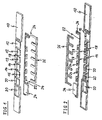
- FIG 1 shows a schematic perspective front view of a control panel in a demounted state according to a preferred embodiment of the present invention.
- the control panel is provided for a domestic appliance.
- the control panel comprises a basic panel 10, a transparent part 22 and a sealing member 26.
- the basic panel 10 is formed as an elongated sheet.
- the basic panel 10 is a single-piece part.
- the basic panel 10 is made of plastics.
- the basic panel 10 is made by an injection moulding.
- the basic panel 10 includes control elements 12 arranged in series.
- the basic panel 10 includes six control elements 12.
- the control elements 12 are formed as flexible tongues. Said flexible tongues are aligned into the same direction.
- the control elements 12 include three free sides, namely two proximal free sides 14 and one distal free side 16.
- the basic panel 10 includes a recess 18.
- Said recess 18 comprises intermediate spaces between neighbouring control elements 12.
- the intermediate space extends between two proximal free sides 14 of the neighbouring control elements 12.
- the recess 18 comprises the space besides the distal free sides 16 of the control elements 12.
- the basic panel 10 comprises a number of cut-outs 20.
- five of the six control elements 12 comprise a medium-sized cut-out 20 in each case. Further one bigger cut-out 20 and three smaller cut-outs 20 are arranged within the proper basic panel 10.
- the transparent part 22 is formed as a skeleton and includes a plurality of transparent elements 24.
- the transparent elements 24 correspond with the cut-outs 20 of the basic panel 10 in respect of their sizes and positions.
- the transparent elements 24 are complementary with the cut-outs 20 of the basic panel 10.
- the transparent part 22 is made of transparent plastics.
- the transparent part 22 can be made by an injection moulding.
- the cut-outs 20 and the corresponding transparent elements 24 are provided to be arranged in front of a light source element in each case. Said light source elements may give information about the status of an appliance controlled by the control panel.
- the sealing member 26 has the form of a rake and is complementary with the recess 18 of the basic panel 10.
- the sealing member 26 is made of an elastic material.
- the sealing member 26 is made of a rubber material.
- the sealing member 26 is made by an over-injection moulding of the rubber material.
- control elements 12 and the elastic rubber material of the sealing member 26 allow a flat control panel. Said control panel can easily be cleaned by wiping. Further, the inventive control panel allows the creation of an advantageous design of said control panel.
- FIG 2 shows a schematic perspective rear view of the control panel in the demounted state according to the preferred embodiment of the present invention.
- the rear sides of the basic panel 10, the transparent part 22 and the sealing member 26 are shown.
- the basic panel 10 includes the control elements 12, the recess 18 and the cut-outs 20.
- the transparent part 22 is formed as the skeleton and includes the plurality of transparent elements 24.
- the sealing member 26 has the formed of the rake and is complementary with the recess 18 of the basic panel 10.
- control elements 12 comprise a fixing element 28 in each case.
- Said fixing element 28 is formed as a cross-shaped salient.
- the fixing element 28 is provided for fastening an electric contact element, which is one part of a pair of electric contact elements.
- the corresponding electric contact elements are arranged at another part of the domestic appliance, at which also the control panel may be attached.
- the control element 12 and the pair of electric contact elements form an electric switch.
- the electric contact elements are arranged behind the basic panel 10, so that the pair of the electric contact elements contacts by pressing against the front side of the corresponding control element 12.
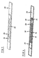
- FIG 3 shows a schematic perspective front view of the control panel in a mounted state according to the preferred embodiment of the present invention.
- the transparent part 22 and the sealing member 26 are inserted within the basic panel 10.
- the transparent elements 24 of the transparent part 22 fill the cut-outs 20 of the basic panel 10.
- the sealing member 26 fills the recess 18 of the basic panel 10.
- FIG 3 clarifies that the control panel has a smooth surface at its front side.
- FIG 4 shows a schematic perspective rear view of the control panel in the mounted state according to the preferred embodiment of the present invention.
- FIG 4 clarifies that the control panel in the mounted state is very flat.
- FIG 5 shows a detailed rear view of a central portion of the control panel in the mounted state according to the preferred embodiment of the present invention.
- FIG 5 clarifies that the sealing member 26 fills completely the recess 18 of the basic panel 10.
- the transparent elements 24 of the transparent part 22 fill completely the cut-outs 20 of the basic panel 10.
- FIG 6 shows a schematic perspective view of a section of a dishwasher door 30 with the control panel according to the preferred embodiment of the present invention.
- the dishwasher is a preferred application of the inventive control panel.
- the control panel is arranged within the upper narrow side of the dishwasher door 30.
- the surfaces of the basic panel 10, the transparent elements 24 and the sealing member 26 are substantially within the same level as the surface of the upper narrow side of the dishwasher door 30.
- a front panel 32 is attached at the front side of the dishwasher door 30.
- the inventive control panel allows a compact arrangement of the control elements 12 at a narrow side of the door of a domestic appliance.
- FIG 7 shows a schematic top view of the section of the dish washer door with the control panel according to the preferred embodiment of the present invention.
- FIG 7 clarifies the dimensions of the basic panel 10, the transparent elements 24 and the sealing member 26 compared with the upper narrow side of the dishwasher door 30.
- an elastic sheet may be arranged at the front side of the basic panel 10.
- said elastic sheet is at least partially transparent.
- the elastic sheet may be printed with symbols describing the functions of the control elements 12.
Landscapes
- Casings For Electric Apparatus (AREA)
- Washing And Drying Of Tableware (AREA)
Abstract
Description
- The present invention relates to a control panel for a domestic appliance. Further, the present invention relates to a domestic appliance with a control panel.
- Domestic appliances are controlled by one or more mechanical push-buttons. Said push-buttons are moveable within a cut-out of a control panel. An electronic device is arranged behind the control panel. The push-buttons are independent form each other.
- However, the external alignment of the push-buttons is not always perfect, since the push-buttons are fixed on a flexible part of the electronic device. The push-buttons have a big height and require a big space above the control panel. It is difficult to clean such kinds of push-buttons. Further, the possibilities for creating the design of the control panel are restricted.
- It is the object of the present invention to provide an improved control panel for a domestic appliance and a corresponding domestic appliance with a control panel, wherein the control panel has a compact design and can easily be cleaned.
- This object is achieved by the control panel for the domestic appliance according to claim 1.
- According to the present invention:
- the control panel comprises at least one basic panel,
- the control panel comprises at least one control element,
- at least one control element is formed as a flexible tongue connected to the basic panel,
- the control element corresponds with at least one pair of electric contact elements,
- the pair of the electric contact elements is arranged behind the basic panel, so that the pair of the electric contact elements contacts by pressing against a front side of the corresponding control element, and
- the control panel comprises at least one elastic sealing member connected to at least one free side of the control element.
- The core of the present invention is the combination of the control element formed as the flexible tongue at the basic panel and the elastic sealing member connected to free sides of the control element. This constellation allows a flat and compact arrangement of the control panel.
- According to the preferred embodiment of the present invention the control panel comprises at least two control elements formed as flexible tongues and arranged in series, wherein the sealing member is connected to proximal free sides of two neighbouring control elements. The series of control elements allows an elongated control panel.
- Further, the sealing member may fill an intermediate space between two proximal free sides of two neighbouring control elements. In a similar way, the sealing member may enclose circumferentially the proximal free sides and a distal free side of at least one control element.
- Preferably, at least a part of the basic panel with the control elements is formed as an elongated single-piece sheet. Such a control panel may be attached at narrow surfaces of the domestic appliance.
- According to the preferred embodiment of the present invention the basic panel includes at least one recess including the at least one intermediate space between the proximal free sides of neighbouring control elements and a space besides the distal free side of the control elements, wherein the sealing member fills at least partially said recess. This allows a continuous surface of the control panel.
- Further, the basic panel and/or at least one control element, respectively, may comprise at least one cut-out provided for receiving a transparent element. Thus, a light source element may be arranged behind the control panel. Said light source element can give information of the status of the domestic appliance.
- Preferably, at least a part of the transparent elements are formed as at least one transparent skeleton part. The transparent skeleton part allows an easy production of the control panel.
- At least a part of the basic panel with the control elements may be made of plastics, in particular by an injection moulding. In a similar way, at least a part of the sealing member may be made by an over-injection moulding of a rubber material. This contributes also to an easy production by low costs.
- Additionally, an elastic sheet may be arranged at the front side of the basic panel, wherein said elastic sheet is partially transparent and partially printed.
- In particular, the control panel is provided for a narrow side of a door at the domestic appliance.
- The object of the present invention is further achieved by a domestic appliance with at least one control panel, wherein the domestic appliance includes at least one control panel as described above.
- For example, the control panel may be arranged on a narrow side of a door at the domestic appliance, in particular on an upper narrow side of a front door at the domestic appliance.
- At last, the domestic appliance may be a dish washer. The inventive control panel allows a compact arrangement of the dishwasher, in particular of the dishwasher door.
- The invention will be explained in more detail below by means of an exemplary embodiment. Reference is thereby made to the accompanied drawings, wherein
- FIG 1
- shows a schematic perspective front view of a control panel in a demounted state according to a preferred embodiment of the present invention,
- FIG 2
- shows a schematic perspective rear view of the control panel in the demounted state according to the pre- ferred embodiment of the present invention,
- FIG 3
- shows a schematic perspective front view of the con- trol panel in a mounted state according to the pre- ferred embodiment of the present invention,
- FIG 4
- shows a schematic perspective rear view of the control panel in the mounted state according to the preferred embodiment of the present invention,
- FIG 5
- shows a detailed rear view of a central portion of the control panel in the mounted state according to the preferred embodiment of the present invention,
- FIG 6
- shows a schematic perspective view of a section of a dish washer door with the control panel according to the preferred embodiment of the present invention, and
- FIG 7
- shows a schematic top view of the section of the dish washer door with the control panel according to the preferred embodiment of the present invention.
-
FIG 1 shows a schematic perspective front view of a control panel in a demounted state according to a preferred embodiment of the present invention. The control panel is provided for a domestic appliance. The control panel comprises abasic panel 10, atransparent part 22 and asealing member 26. - The
basic panel 10 is formed as an elongated sheet. In this example thebasic panel 10 is a single-piece part. Thebasic panel 10 is made of plastics. For example, thebasic panel 10 is made by an injection moulding. - The
basic panel 10 includescontrol elements 12 arranged in series. In this example thebasic panel 10 includes sixcontrol elements 12. Thecontrol elements 12 are formed as flexible tongues. Said flexible tongues are aligned into the same direction. Thecontrol elements 12 include three free sides, namely two proximalfree sides 14 and one distalfree side 16. - The
basic panel 10 includes arecess 18. Saidrecess 18 comprises intermediate spaces between neighbouringcontrol elements 12. The intermediate space extends between two proximalfree sides 14 of the neighbouringcontrol elements 12. Further, therecess 18 comprises the space besides the distalfree sides 16 of thecontrol elements 12. - The
basic panel 10 comprises a number of cut-outs 20. In this example, five of the sixcontrol elements 12 comprise a medium-sized cut-out 20 in each case. Further one bigger cut-out 20 and three smaller cut-outs 20 are arranged within the properbasic panel 10. - The
transparent part 22 is formed as a skeleton and includes a plurality oftransparent elements 24. Thetransparent elements 24 correspond with the cut-outs 20 of thebasic panel 10 in respect of their sizes and positions. Thetransparent elements 24 are complementary with the cut-outs 20 of thebasic panel 10. For example, thetransparent part 22 is made of transparent plastics. Thetransparent part 22 can be made by an injection moulding. - The cut-
outs 20 and the correspondingtransparent elements 24 are provided to be arranged in front of a light source element in each case. Said light source elements may give information about the status of an appliance controlled by the control panel. - The sealing
member 26 has the form of a rake and is complementary with therecess 18 of thebasic panel 10. The sealingmember 26 is made of an elastic material. In particular, the sealingmember 26 is made of a rubber material. For example, the sealingmember 26 is made by an over-injection moulding of the rubber material. - The flexible tongues as
control elements 12 and the elastic rubber material of the sealingmember 26 allow a flat control panel. Said control panel can easily be cleaned by wiping. Further, the inventive control panel allows the creation of an advantageous design of said control panel. -
FIG 2 shows a schematic perspective rear view of the control panel in the demounted state according to the preferred embodiment of the present invention. The rear sides of thebasic panel 10, thetransparent part 22 and the sealingmember 26 are shown. - The
basic panel 10 includes thecontrol elements 12, therecess 18 and the cut-outs 20. Thetransparent part 22 is formed as the skeleton and includes the plurality oftransparent elements 24. The sealingmember 26 has the formed of the rake and is complementary with therecess 18 of thebasic panel 10. - Further, at their rear sides the
control elements 12 comprise a fixingelement 28 in each case. Said fixingelement 28 is formed as a cross-shaped salient. The fixingelement 28 is provided for fastening an electric contact element, which is one part of a pair of electric contact elements. The corresponding electric contact elements are arranged at another part of the domestic appliance, at which also the control panel may be attached. Thecontrol element 12 and the pair of electric contact elements form an electric switch. The electric contact elements are arranged behind thebasic panel 10, so that the pair of the electric contact elements contacts by pressing against the front side of thecorresponding control element 12. -
FIG 3 shows a schematic perspective front view of the control panel in a mounted state according to the preferred embodiment of the present invention. Thetransparent part 22 and the sealingmember 26 are inserted within thebasic panel 10. Thetransparent elements 24 of thetransparent part 22 fill the cut-outs 20 of thebasic panel 10. The sealingmember 26 fills therecess 18 of thebasic panel 10.FIG 3 clarifies that the control panel has a smooth surface at its front side. -
FIG 4 shows a schematic perspective rear view of the control panel in the mounted state according to the preferred embodiment of the present invention.FIG 4 clarifies that the control panel in the mounted state is very flat. -
FIG 5 shows a detailed rear view of a central portion of the control panel in the mounted state according to the preferred embodiment of the present invention.FIG 5 clarifies that the sealingmember 26 fills completely therecess 18 of thebasic panel 10. In a similar way, thetransparent elements 24 of thetransparent part 22 fill completely the cut-outs 20 of thebasic panel 10.FIG 6 shows a schematic perspective view of a section of adishwasher door 30 with the control panel according to the preferred embodiment of the present invention. The dishwasher is a preferred application of the inventive control panel. - The control panel is arranged within the upper narrow side of the
dishwasher door 30. The surfaces of thebasic panel 10, thetransparent elements 24 and the sealingmember 26 are substantially within the same level as the surface of the upper narrow side of thedishwasher door 30. Further, a front panel 32 is attached at the front side of thedishwasher door 30. - The inventive control panel allows a compact arrangement of the
control elements 12 at a narrow side of the door of a domestic appliance. -
FIG 7 shows a schematic top view of the section of the dish washer door with the control panel according to the preferred embodiment of the present invention.FIG 7 clarifies the dimensions of thebasic panel 10, thetransparent elements 24 and the sealingmember 26 compared with the upper narrow side of thedishwasher door 30. - At last, an elastic sheet may be arranged at the front side of the
basic panel 10. Preferably, said elastic sheet is at least partially transparent. Additionally, the elastic sheet may be printed with symbols describing the functions of thecontrol elements 12. - Although illustrative embodiments of the present invention have been described herein with reference to the accompanying drawings, it is to be understood that the present invention is not limited to this precise embodiment, and that various other changes and modifications may be affected therein by one skilled in the art without departing from the scope or spirit of the invention. All such changes and modifications are intended to be included within the scope of the invention as defined by the appended claims.
-
- 10
- basic panel
- 12
- control element
- 14
- proximate free side
- 16
- distal free side
- 18
- recess
- 20
- cut-out
- 22
- transparent part, skeleton part
- 24
- transparent element
- 26
- sealing member
- 28
- fixing element
- 30
- dishwasher door
- 32
- front panel
Claims (15)
- A control panel for a domestic appliance, wherein:- the control panel comprises at least one basic panel (10),- the control panel comprises at least one control element (12),- at least one control element (12) is formed as a flexible tongue connected to the basic panel (10),- the control element (12) corresponds with at least one pair of electric contact elements,- the pair of the electric contact elements is arranged behind the basic panel (10), so that the pair of the electric contact elements contacts by pressing against a front side of the corresponding control element (12), and- the control panel comprises at least one elastic sealing member (26) connected to at least one free side of the control element (12).
- The control panel according to claim 1,
characterized in that
the control panel comprises at least two control elements (12) formed as flexible tongues and arranged in series, wherein the sealing member (26) is connected to proximal free sides (14) of two neighbouring control elements (12). - The control panel according to claim 2,
characterized in that
the sealing member (26) fills an intermediate space between two proximal free sides (14) of two neighbouring control elements (12). - The control panel according to any one of the preceding claims,
characterized in that
the sealing member (22) encloses circumferentially the proximal free sides (14) and a distal free side (16) of at least one control element (12). - The control panel according to any one of the preceding claims,
characterized in that
at least a part of the basic panel (10) with the control elements (12) is formed as an elongated single-piece sheet. - The control panel according to any one of the preceding claims,
characterized in that
the basic panel (10) includes at least one recess (18) including the at least one intermediate space between the proximal free sides (14) of neighbouring control elements (12) and a space besides the distal free side (16) of the control elements (12), wherein the sealing member (22) fills at least partially said recess (18). - The control panel according to any one of the preceding claims,
characterized in that
the basic panel (10) and/or at least one control element (12), respectively, comprise at least one cut-out (20) provided for receiving a transparent element (26). - The control panel according to any one of the preceding claims,
characterized in that
at least a part of the transparent elements (24) are formed as at least one transparent skeleton part (22). - The control panel according to any one of the preceding claims,
characterized in that
at least a part of the basic panel (10) with the control elements (12) is made of plastics, in particular by an injection moulding. - The control panel according to any one of the preceding claims,
characterized in that
at least a part of the sealing member (26) is made by an over-injection moulding of a rubber material. - The control panel according to any one of the preceding claims,
characterized in that
an elastic sheet is arranged at the front side of the basic panel (10), wherein said elastic sheet is partially transparent and partially printed. - The control panel according to any one of the preceding claims,
characterized in that
the control panel is provided for a narrow side of a door (30) at the domestic appliance. - A domestic appliance with at least one control panel, characterized in that
the domestic appliance includes at least one control panel according to any one of the preceding claims 1 to 12. - The domestic appliance according to claim 13, characterized in that
the control panel is arranged on a narrow side of a door (30) at the domestic appliance, in particular on an upper narrow side of a front door (30) at the domestic appliance. - A domestic appliance according to any one of the claims 12 to 14,
characterized in that
the domestic appliance is a dish washer.
Priority Applications (2)
| Application Number | Priority Date | Filing Date | Title |
|---|---|---|---|
| PL09011335T PL2292135T3 (en) | 2009-09-03 | 2009-09-03 | A control panel for a domestic appliance |
| EP09011335.8A EP2292135B1 (en) | 2009-09-03 | 2009-09-03 | A control panel for a domestic appliance |
Applications Claiming Priority (1)
| Application Number | Priority Date | Filing Date | Title |
|---|---|---|---|
| EP09011335.8A EP2292135B1 (en) | 2009-09-03 | 2009-09-03 | A control panel for a domestic appliance |
Publications (2)
| Publication Number | Publication Date |
|---|---|
| EP2292135A1 true EP2292135A1 (en) | 2011-03-09 |
| EP2292135B1 EP2292135B1 (en) | 2020-06-17 |
Family
ID=41506561
Family Applications (1)
| Application Number | Title | Priority Date | Filing Date |
|---|---|---|---|
| EP09011335.8A Active EP2292135B1 (en) | 2009-09-03 | 2009-09-03 | A control panel for a domestic appliance |
Country Status (2)
| Country | Link |
|---|---|
| EP (1) | EP2292135B1 (en) |
| PL (1) | PL2292135T3 (en) |
Citations (8)
| Publication number | Priority date | Publication date | Assignee | Title |
|---|---|---|---|---|
| DE3305556C1 (en) * | 1983-02-18 | 1984-09-13 | Philips Patentverwaltung Gmbh, 2000 Hamburg | Keyboard switch panel for an electrical apparatus |
| DE29715337U1 (en) * | 1997-08-27 | 1997-12-11 | Schwarzbich, Jörg, 33615 Bielefeld | Key unit |
| US20040026222A1 (en) * | 2002-06-27 | 2004-02-12 | Yazaki Corporation | Slim switch |
| US20060001648A1 (en) * | 2004-06-01 | 2006-01-05 | Lg Electronics Inc. | Button assembly of control panel assembly |
| EP1662207A1 (en) * | 2004-11-30 | 2006-05-31 | Diehl AKO Stiftung & Co. KG | Control device for a household appliance |
| DE102006026910A1 (en) * | 2006-06-09 | 2007-12-13 | BSH Bosch und Siemens Hausgeräte GmbH | Operating unit for a household appliance |
| US20080273016A1 (en) * | 2007-05-04 | 2008-11-06 | Electrolux Home Products, Inc. | Integrated touch-screen control panel for a washing appliance and method for producing the same |
| EP2012334A1 (en) * | 2007-07-06 | 2009-01-07 | Electrolux Home Products Corporation N.V. | Integrated control panel for household appliances |
-
2009
- 2009-09-03 PL PL09011335T patent/PL2292135T3/en unknown
- 2009-09-03 EP EP09011335.8A patent/EP2292135B1/en active Active
Patent Citations (8)
| Publication number | Priority date | Publication date | Assignee | Title |
|---|---|---|---|---|
| DE3305556C1 (en) * | 1983-02-18 | 1984-09-13 | Philips Patentverwaltung Gmbh, 2000 Hamburg | Keyboard switch panel for an electrical apparatus |
| DE29715337U1 (en) * | 1997-08-27 | 1997-12-11 | Schwarzbich, Jörg, 33615 Bielefeld | Key unit |
| US20040026222A1 (en) * | 2002-06-27 | 2004-02-12 | Yazaki Corporation | Slim switch |
| US20060001648A1 (en) * | 2004-06-01 | 2006-01-05 | Lg Electronics Inc. | Button assembly of control panel assembly |
| EP1662207A1 (en) * | 2004-11-30 | 2006-05-31 | Diehl AKO Stiftung & Co. KG | Control device for a household appliance |
| DE102006026910A1 (en) * | 2006-06-09 | 2007-12-13 | BSH Bosch und Siemens Hausgeräte GmbH | Operating unit for a household appliance |
| US20080273016A1 (en) * | 2007-05-04 | 2008-11-06 | Electrolux Home Products, Inc. | Integrated touch-screen control panel for a washing appliance and method for producing the same |
| EP2012334A1 (en) * | 2007-07-06 | 2009-01-07 | Electrolux Home Products Corporation N.V. | Integrated control panel for household appliances |
Also Published As
| Publication number | Publication date |
|---|---|
| PL2292135T3 (en) | 2020-11-16 |
| EP2292135B1 (en) | 2020-06-17 |
Similar Documents
| Publication | Publication Date | Title |
|---|---|---|
| EP2997660B1 (en) | Touch and/or proximity-sensitive actuation element | |
| EP2390577B1 (en) | Method of mounting a user interface for an appliance of household or industrial type | |
| US20060114128A1 (en) | Operating device for a domestic electrical appliance | |
| PL1664415T3 (en) | Household appliance with a panel assembly | |
| RU2685992C2 (en) | Electronic user interface with separate control panel and home appliance with such user interface | |
| US8937261B2 (en) | Operator control apparatus for an electrical household appliance | |
| CN105304369A (en) | Button switch | |
| EP2292135B1 (en) | A control panel for a domestic appliance | |
| EP2360308B1 (en) | A control panel for a household appliance | |
| WO2003044955A3 (en) | Electric domestic appliance | |
| RU2479010C2 (en) | Household electric appliance integrated control panel | |
| EP2375204B1 (en) | Display panel assembly for electrical appliances | |
| WO2012032007A1 (en) | A domestic appliance comprising top plate | |
| CN106574423B (en) | Display device with display and the household appliance with such display device | |
| EP1321090A2 (en) | Electric household appliance, in particular a dishwashing machine, with an improved access door | |
| EP2541771B1 (en) | Method of manufacturing an electrical switching element | |
| CN2505972Y (en) | Pushbutton structure of household electric appliance control board | |
| DE202013004775U1 (en) | Touch and / or proximity sensitive actuator | |
| KR102715406B1 (en) | Remote control button assembly | |
| KR200429935Y1 (en) | Fixed structure of button switch for electronics | |
| EP2733715B1 (en) | Operating device | |
| CN210004471U (en) | cooking utensils | |
| ITPN990059A1 (en) | HOUSEHOLD APPLIANCE, IN PARTICULAR REFRIGERATOR AND / OR FREEZER WITH A CONTROL PANEL | |
| AU2018274879B2 (en) | Button assembly for push-button switch, push-button switch, and electronic device | |
| KR200388971Y1 (en) | A mechanical membrane switch |
Legal Events
| Date | Code | Title | Description |
|---|---|---|---|
| PUAI | Public reference made under article 153(3) epc to a published international application that has entered the european phase |
Free format text: ORIGINAL CODE: 0009012 |
|
| AK | Designated contracting states |
Kind code of ref document: A1 Designated state(s): AT BE BG CH CY CZ DE DK EE ES FI FR GB GR HR HU IE IS IT LI LT LU LV MC MK MT NL NO PL PT RO SE SI SK SM TR |
|
| AX | Request for extension of the european patent |
Extension state: AL BA RS |
|
| RAP1 | Party data changed (applicant data changed or rights of an application transferred) |
Owner name: ELECTROLUX HOME PRODUCTS CORPORATION N.V. |
|
| RAP1 | Party data changed (applicant data changed or rights of an application transferred) |
Owner name: ELECTROLUX HOME PRODUCTS CORPORATION N.V. |
|
| 17P | Request for examination filed |
Effective date: 20110826 |
|
| 17Q | First examination report despatched |
Effective date: 20110913 |
|
| STAA | Information on the status of an ep patent application or granted ep patent |
Free format text: STATUS: EXAMINATION IS IN PROGRESS |
|
| GRAP | Despatch of communication of intention to grant a patent |
Free format text: ORIGINAL CODE: EPIDOSNIGR1 |
|
| STAA | Information on the status of an ep patent application or granted ep patent |
Free format text: STATUS: GRANT OF PATENT IS INTENDED |
|
| INTG | Intention to grant announced |
Effective date: 20200131 |
|
| GRAS | Grant fee paid |
Free format text: ORIGINAL CODE: EPIDOSNIGR3 |
|
| GRAA | (expected) grant |
Free format text: ORIGINAL CODE: 0009210 |
|
| STAA | Information on the status of an ep patent application or granted ep patent |
Free format text: STATUS: THE PATENT HAS BEEN GRANTED |
|
| AK | Designated contracting states |
Kind code of ref document: B1 Designated state(s): AT BE BG CH CY CZ DE DK EE ES FI FR GB GR HR HU IE IS IT LI LT LU LV MC MK MT NL NO PL PT RO SE SI SK SM TR |
|
| REG | Reference to a national code |
Ref country code: GB Ref legal event code: FG4D |
|
| REG | Reference to a national code |
Ref country code: CH Ref legal event code: EP |
|
| REG | Reference to a national code |
Ref country code: DE Ref legal event code: R096 Ref document number: 602009062242 Country of ref document: DE |
|
| REG | Reference to a national code |
Ref country code: IE Ref legal event code: FG4D |
|
| REG | Reference to a national code |
Ref country code: AT Ref legal event code: REF Ref document number: 1280338 Country of ref document: AT Kind code of ref document: T Effective date: 20200715 |
|
| PG25 | Lapsed in a contracting state [announced via postgrant information from national office to epo] |
Ref country code: FI Free format text: LAPSE BECAUSE OF FAILURE TO SUBMIT A TRANSLATION OF THE DESCRIPTION OR TO PAY THE FEE WITHIN THE PRESCRIBED TIME-LIMIT Effective date: 20200617 Ref country code: LT Free format text: LAPSE BECAUSE OF FAILURE TO SUBMIT A TRANSLATION OF THE DESCRIPTION OR TO PAY THE FEE WITHIN THE PRESCRIBED TIME-LIMIT Effective date: 20200617 Ref country code: NO Free format text: LAPSE BECAUSE OF FAILURE TO SUBMIT A TRANSLATION OF THE DESCRIPTION OR TO PAY THE FEE WITHIN THE PRESCRIBED TIME-LIMIT Effective date: 20200917 Ref country code: GR Free format text: LAPSE BECAUSE OF FAILURE TO SUBMIT A TRANSLATION OF THE DESCRIPTION OR TO PAY THE FEE WITHIN THE PRESCRIBED TIME-LIMIT Effective date: 20200918 Ref country code: SE Free format text: LAPSE BECAUSE OF FAILURE TO SUBMIT A TRANSLATION OF THE DESCRIPTION OR TO PAY THE FEE WITHIN THE PRESCRIBED TIME-LIMIT Effective date: 20200617 |
|
| PGFP | Annual fee paid to national office [announced via postgrant information from national office to epo] |
Ref country code: DE Payment date: 20200925 Year of fee payment: 12 Ref country code: GB Payment date: 20200922 Year of fee payment: 12 |
|
| REG | Reference to a national code |
Ref country code: LT Ref legal event code: MG4D |
|
| REG | Reference to a national code |
Ref country code: NL Ref legal event code: MP Effective date: 20200617 |
|
| PG25 | Lapsed in a contracting state [announced via postgrant information from national office to epo] |
Ref country code: BG Free format text: LAPSE BECAUSE OF FAILURE TO SUBMIT A TRANSLATION OF THE DESCRIPTION OR TO PAY THE FEE WITHIN THE PRESCRIBED TIME-LIMIT Effective date: 20200917 Ref country code: HR Free format text: LAPSE BECAUSE OF FAILURE TO SUBMIT A TRANSLATION OF THE DESCRIPTION OR TO PAY THE FEE WITHIN THE PRESCRIBED TIME-LIMIT Effective date: 20200617 Ref country code: LV Free format text: LAPSE BECAUSE OF FAILURE TO SUBMIT A TRANSLATION OF THE DESCRIPTION OR TO PAY THE FEE WITHIN THE PRESCRIBED TIME-LIMIT Effective date: 20200617 |
|
| REG | Reference to a national code |
Ref country code: AT Ref legal event code: MK05 Ref document number: 1280338 Country of ref document: AT Kind code of ref document: T Effective date: 20200617 |
|
| PG25 | Lapsed in a contracting state [announced via postgrant information from national office to epo] |
Ref country code: NL Free format text: LAPSE BECAUSE OF FAILURE TO SUBMIT A TRANSLATION OF THE DESCRIPTION OR TO PAY THE FEE WITHIN THE PRESCRIBED TIME-LIMIT Effective date: 20200617 |
|
| PG25 | Lapsed in a contracting state [announced via postgrant information from national office to epo] |
Ref country code: EE Free format text: LAPSE BECAUSE OF FAILURE TO SUBMIT A TRANSLATION OF THE DESCRIPTION OR TO PAY THE FEE WITHIN THE PRESCRIBED TIME-LIMIT Effective date: 20200617 Ref country code: AT Free format text: LAPSE BECAUSE OF FAILURE TO SUBMIT A TRANSLATION OF THE DESCRIPTION OR TO PAY THE FEE WITHIN THE PRESCRIBED TIME-LIMIT Effective date: 20200617 Ref country code: RO Free format text: LAPSE BECAUSE OF FAILURE TO SUBMIT A TRANSLATION OF THE DESCRIPTION OR TO PAY THE FEE WITHIN THE PRESCRIBED TIME-LIMIT Effective date: 20200617 Ref country code: ES Free format text: LAPSE BECAUSE OF FAILURE TO SUBMIT A TRANSLATION OF THE DESCRIPTION OR TO PAY THE FEE WITHIN THE PRESCRIBED TIME-LIMIT Effective date: 20200617 Ref country code: CZ Free format text: LAPSE BECAUSE OF FAILURE TO SUBMIT A TRANSLATION OF THE DESCRIPTION OR TO PAY THE FEE WITHIN THE PRESCRIBED TIME-LIMIT Effective date: 20200617 Ref country code: PT Free format text: LAPSE BECAUSE OF FAILURE TO SUBMIT A TRANSLATION OF THE DESCRIPTION OR TO PAY THE FEE WITHIN THE PRESCRIBED TIME-LIMIT Effective date: 20201019 Ref country code: SM Free format text: LAPSE BECAUSE OF FAILURE TO SUBMIT A TRANSLATION OF THE DESCRIPTION OR TO PAY THE FEE WITHIN THE PRESCRIBED TIME-LIMIT Effective date: 20200617 |
|
| PGFP | Annual fee paid to national office [announced via postgrant information from national office to epo] |
Ref country code: IT Payment date: 20201013 Year of fee payment: 12 |
|
| PG25 | Lapsed in a contracting state [announced via postgrant information from national office to epo] |
Ref country code: IS Free format text: LAPSE BECAUSE OF FAILURE TO SUBMIT A TRANSLATION OF THE DESCRIPTION OR TO PAY THE FEE WITHIN THE PRESCRIBED TIME-LIMIT Effective date: 20201017 Ref country code: SK Free format text: LAPSE BECAUSE OF FAILURE TO SUBMIT A TRANSLATION OF THE DESCRIPTION OR TO PAY THE FEE WITHIN THE PRESCRIBED TIME-LIMIT Effective date: 20200617 |
|
| PGFP | Annual fee paid to national office [announced via postgrant information from national office to epo] |
Ref country code: PL Payment date: 20201005 Year of fee payment: 12 |
|
| REG | Reference to a national code |
Ref country code: DE Ref legal event code: R097 Ref document number: 602009062242 Country of ref document: DE |
|
| PLBE | No opposition filed within time limit |
Free format text: ORIGINAL CODE: 0009261 |
|
| STAA | Information on the status of an ep patent application or granted ep patent |
Free format text: STATUS: NO OPPOSITION FILED WITHIN TIME LIMIT |
|
| PG25 | Lapsed in a contracting state [announced via postgrant information from national office to epo] |
Ref country code: DK Free format text: LAPSE BECAUSE OF FAILURE TO SUBMIT A TRANSLATION OF THE DESCRIPTION OR TO PAY THE FEE WITHIN THE PRESCRIBED TIME-LIMIT Effective date: 20200617 Ref country code: MC Free format text: LAPSE BECAUSE OF FAILURE TO SUBMIT A TRANSLATION OF THE DESCRIPTION OR TO PAY THE FEE WITHIN THE PRESCRIBED TIME-LIMIT Effective date: 20200617 |
|
| REG | Reference to a national code |
Ref country code: CH Ref legal event code: PL |
|
| 26N | No opposition filed |
Effective date: 20210318 |
|
| PG25 | Lapsed in a contracting state [announced via postgrant information from national office to epo] |
Ref country code: SI Free format text: LAPSE BECAUSE OF FAILURE TO SUBMIT A TRANSLATION OF THE DESCRIPTION OR TO PAY THE FEE WITHIN THE PRESCRIBED TIME-LIMIT Effective date: 20200617 |
|
| REG | Reference to a national code |
Ref country code: BE Ref legal event code: MM Effective date: 20200930 |
|
| PG25 | Lapsed in a contracting state [announced via postgrant information from national office to epo] |
Ref country code: LU Free format text: LAPSE BECAUSE OF NON-PAYMENT OF DUE FEES Effective date: 20200903 |
|
| PG25 | Lapsed in a contracting state [announced via postgrant information from national office to epo] |
Ref country code: FR Free format text: LAPSE BECAUSE OF NON-PAYMENT OF DUE FEES Effective date: 20200930 |
|
| PG25 | Lapsed in a contracting state [announced via postgrant information from national office to epo] |
Ref country code: CH Free format text: LAPSE BECAUSE OF NON-PAYMENT OF DUE FEES Effective date: 20200930 Ref country code: BE Free format text: LAPSE BECAUSE OF NON-PAYMENT OF DUE FEES Effective date: 20200930 Ref country code: LI Free format text: LAPSE BECAUSE OF NON-PAYMENT OF DUE FEES Effective date: 20200930 Ref country code: IE Free format text: LAPSE BECAUSE OF NON-PAYMENT OF DUE FEES Effective date: 20200903 |
|
| REG | Reference to a national code |
Ref country code: DE Ref legal event code: R119 Ref document number: 602009062242 Country of ref document: DE |
|
| GBPC | Gb: european patent ceased through non-payment of renewal fee |
Effective date: 20210903 |
|
| PG25 | Lapsed in a contracting state [announced via postgrant information from national office to epo] |
Ref country code: TR Free format text: LAPSE BECAUSE OF FAILURE TO SUBMIT A TRANSLATION OF THE DESCRIPTION OR TO PAY THE FEE WITHIN THE PRESCRIBED TIME-LIMIT Effective date: 20200617 Ref country code: MT Free format text: LAPSE BECAUSE OF FAILURE TO SUBMIT A TRANSLATION OF THE DESCRIPTION OR TO PAY THE FEE WITHIN THE PRESCRIBED TIME-LIMIT Effective date: 20200617 Ref country code: CY Free format text: LAPSE BECAUSE OF FAILURE TO SUBMIT A TRANSLATION OF THE DESCRIPTION OR TO PAY THE FEE WITHIN THE PRESCRIBED TIME-LIMIT Effective date: 20200617 |
|
| PG25 | Lapsed in a contracting state [announced via postgrant information from national office to epo] |
Ref country code: MK Free format text: LAPSE BECAUSE OF FAILURE TO SUBMIT A TRANSLATION OF THE DESCRIPTION OR TO PAY THE FEE WITHIN THE PRESCRIBED TIME-LIMIT Effective date: 20200617 |
|
| PG25 | Lapsed in a contracting state [announced via postgrant information from national office to epo] |
Ref country code: GB Free format text: LAPSE BECAUSE OF NON-PAYMENT OF DUE FEES Effective date: 20210903 Ref country code: DE Free format text: LAPSE BECAUSE OF NON-PAYMENT OF DUE FEES Effective date: 20220401 |
|
| PG25 | Lapsed in a contracting state [announced via postgrant information from national office to epo] |
Ref country code: IT Free format text: LAPSE BECAUSE OF NON-PAYMENT OF DUE FEES Effective date: 20210903 |
|
| PG25 | Lapsed in a contracting state [announced via postgrant information from national office to epo] |
Ref country code: PL Free format text: LAPSE BECAUSE OF NON-PAYMENT OF DUE FEES Effective date: 20210903 |