EP2291317B1 - Cable transport device - Google Patents
Cable transport device Download PDFInfo
- Publication number
- EP2291317B1 EP2291317B1 EP09750251.2A EP09750251A EP2291317B1 EP 2291317 B1 EP2291317 B1 EP 2291317B1 EP 09750251 A EP09750251 A EP 09750251A EP 2291317 B1 EP2291317 B1 EP 2291317B1
- Authority
- EP
- European Patent Office
- Prior art keywords
- cable
- pressure rollers
- transporter
- transport device
- plate
- Prior art date
- Legal status (The legal status is an assumption and is not a legal conclusion. Google has not performed a legal analysis and makes no representation as to the accuracy of the status listed.)
- Active
Links
Images


Classifications
-
- B—PERFORMING OPERATIONS; TRANSPORTING
- B65—CONVEYING; PACKING; STORING; HANDLING THIN OR FILAMENTARY MATERIAL
- B65H—HANDLING THIN OR FILAMENTARY MATERIAL, e.g. SHEETS, WEBS, CABLES
- B65H51/00—Forwarding filamentary material
- B65H51/02—Rotary devices, e.g. with helical forwarding surfaces
- B65H51/04—Rollers, pulleys, capstans, or intermeshing rotary elements
- B65H51/08—Rollers, pulleys, capstans, or intermeshing rotary elements arranged to operate in groups or in co-operation with other elements
- B65H51/10—Rollers, pulleys, capstans, or intermeshing rotary elements arranged to operate in groups or in co-operation with other elements with opposed coacting surfaces, e.g. providing nips
-
- B—PERFORMING OPERATIONS; TRANSPORTING
- B65—CONVEYING; PACKING; STORING; HANDLING THIN OR FILAMENTARY MATERIAL
- B65H—HANDLING THIN OR FILAMENTARY MATERIAL, e.g. SHEETS, WEBS, CABLES
- B65H51/00—Forwarding filamentary material
- B65H51/32—Supporting or driving arrangements for forwarding devices
-
- B—PERFORMING OPERATIONS; TRANSPORTING
- B65—CONVEYING; PACKING; STORING; HANDLING THIN OR FILAMENTARY MATERIAL
- B65H—HANDLING THIN OR FILAMENTARY MATERIAL, e.g. SHEETS, WEBS, CABLES
- B65H57/00—Guides for filamentary materials; Supports therefor
- B65H57/04—Guiding surfaces within slots or grooves
-
- H—ELECTRICITY
- H01—ELECTRIC ELEMENTS
- H01R—ELECTRICALLY-CONDUCTIVE CONNECTIONS; STRUCTURAL ASSOCIATIONS OF A PLURALITY OF MUTUALLY-INSULATED ELECTRICAL CONNECTING ELEMENTS; COUPLING DEVICES; CURRENT COLLECTORS
- H01R43/00—Apparatus or processes specially adapted for manufacturing, assembling, maintaining, or repairing of line connectors or current collectors or for joining electric conductors
- H01R43/04—Apparatus or processes specially adapted for manufacturing, assembling, maintaining, or repairing of line connectors or current collectors or for joining electric conductors for forming connections by deformation, e.g. crimping tool
- H01R43/048—Crimping apparatus or processes
- H01R43/052—Crimping apparatus or processes with wire-feeding mechanism
-
- B—PERFORMING OPERATIONS; TRANSPORTING
- B65—CONVEYING; PACKING; STORING; HANDLING THIN OR FILAMENTARY MATERIAL
- B65H—HANDLING THIN OR FILAMENTARY MATERIAL, e.g. SHEETS, WEBS, CABLES
- B65H2404/00—Parts for transporting or guiding the handled material
- B65H2404/10—Rollers
- B65H2404/14—Roller pairs
- B65H2404/142—Roller pairs arranged on movable frame
- B65H2404/1421—Roller pairs arranged on movable frame rotating, pivoting or oscillating around an axis, e.g. parallel to the roller axis
-
- B—PERFORMING OPERATIONS; TRANSPORTING
- B65—CONVEYING; PACKING; STORING; HANDLING THIN OR FILAMENTARY MATERIAL
- B65H—HANDLING THIN OR FILAMENTARY MATERIAL, e.g. SHEETS, WEBS, CABLES
- B65H2701/00—Handled material; Storage means
- B65H2701/30—Handled filamentary material
- B65H2701/39—Other types of filamentary materials or special applications
- B65H2701/3911—Chains
Definitions
- the invention relates to a cable transport device having a pivotably mounted cable transporter for a cable to be drawn in and to be transported, a first drive means connected in a stationary manner to a base frame and intended for achieving an exactly defined pivot movement of the cable transporter around a pivot axis and a second drive means for synchronously driving at least two cooperating pressure rollers, at least one pressure roller being arranged so as to be laterally adjustable, according to the preamble of claim 1 and/or claim 2.
- Cable transport devices are known, for example from a CrimpCenter of the applicant. Such cable transport devices are fixed in a stationary manner on a base frame. A first gripper is arranged in the cable transport axis on the base frame on a pivot device having a moveable guide carriage, this gripper cooperating with processing stations, for example with a cutting and insulation stripping station arranged in the cable transport axis and with a crimping device arranged outside the cable transport axis.
- the electric cable is led from a store, for example from a cable drum, through a guide sleeve and two alignment units to a cable transporter. In the cable transporter, the cable is clamped between two coated toothed belts.
- the toothed belts are each driven by drive and deflection belt sprockets and supported several times by smaller belt sprockets in the region between the drive and deflection belt sprockets.
- the two toothed belts are pressed by a suitable pressing device, for example pneumatically, with a force against one another so that there is sufficient frictional force between the coated toothed belts and the cable to be transported between the toothed belt coatings.
- the cable transporter is driven by a controlled servo drive motor. In this way, the clamped cable present between the toothed belts is transported in the longitudinal direction.
- a measuring wheel of a longitudinal measuring device which measuring wheel rests with spring force outside the transport system against the cable, detects the required cable length with the aid of an encoder.
- the signals of this encoder are fed into the control of the servo motor so that the process for cutting the cable to length is controlled in this way.
- the cable is led through guide sleeves and a guide tube from the cable transporter into the working region of a cutting and insulation stripping station and is gripped by the first gripper at the cable beginning.
- the zero cut is now carried out at the cable beginning in the cutting and insulation stripping station and is detected by the measuring wheel. This is followed by the stripping of insulation from the cable beginning.
- the pivot device then pivots the gripper to the laterally arranged processing stations where, for example, a seal and/or a crimp contact is mounted on the cable end stripped of insulation.
- the gripper arranged on a pivot device could be omitted if the cable transport device was mounted on a pivot device. In this way, the distance between the cable transport device and the processing stations was considerably reduced.
- a disadvantage of this device is, however, the complicated design for force transmission via a plurality of axes of rotation.
- Another disadvantage is that the drive motor responsible for the cable transport is arranged directly on the pivot device and must be concomitantly swiveled by the drive motor responsible for the pivoting process.
- EP 0 708 050 B1 provides, on the cable feed side, an entry cable guide connected to a flexible guide tube and, on the cable delivery side, an exit cable guide.
- a guide sleeve in the form of a tube has the disadvantage that it too has to be replaced when changing to a cable having a different cross-section and the cable has to be threaded again. Such a procedure is complicated and considerably increases the changeover times.
- the second drive means is having a drive axle for the pressure rollers of the cable conveyor that is connected in a stationary manner to the base frame, and the drive axle of the second drive means coincides with the pivot axis for the cable transporter.
- the second drive means is having a drive axle for the pressure rollers of the cable conveyor likewise connected in a stationary manner to the base frame, the axes of rotation are parallel to one another and parallel to a common pitch axis, and the transmission of the pivot movement takes place via a toothed belt which is clamped symmetrically relative to the center of rotation of the pivot axis of the first drive means between a first intermediate shaft arranged on a base plate of the cable transporter and a second intermediate shaft fixed to the machine frame, the pitch axis of the cable transporter being identical to the axis of the first intermediate shaft.
- a pivotable cable transport device is also substantially more material- and space-saving than comparable cable devices of the prior art.
- At least two pressure rollers are rotatably mounted on the base plate of the cable transporter on one axis of rotation each and in that at least two pressure rollers are likewise rotatably mounted on an adjustable plate on one axis of rotation each, the respective axes of rotation of the pressure rollers being arranged opposite one another, and that, between two pressure rollers, a measuring wheel for measuring the required cable length rests directly against the transported cable and, between two pressure rollers, a counter-wheel rests directly against the transported cable, or vice versa.
- belt sprockets which have a drive connection via a double-sided toothed belt to a second drive belt sprocket arranged on the drive axle of the second drive means are arranged on the axes of rotation of the pressure rollers on the underside of the cable transporter, the toothed belt transmitting the rotation of the drive belt sprocket to the pressure rollers arranged on the adjustable plate and that the toothed belt is clamped diagonally between the belt sprockets of the pressure rollers and the belt sprockets of the pressure rollers, resulting in the counter clockwise movement of the pressure rollers and the clockwise movement of the pressure rollers.
- a further advantageous embodiment of the device according to any of the preceding paragraphs is characterized in that the adjustable plate moves away from the base plate of the cable transporter for the purpose of inserting the cable to be transported and, after insertion of the cable between the pressure rollers, the adjustable plate moves by means of compressed air or by means of the pressure of a mechanical energy accumulator to a position in which the pressure rollers and the measuring wheel and the counter-wheel press with a defined force onto the cable to be transported and that the base plate of the cable transporter together with the adjustable plate on the drive axle and/or on the pitch axis are mounted so as to be pivotable together.
- a pressure mechanism controls the pressure on the cable to be transported, by the pressure rollers mounted in a fixed manner on the adjustable plate relative to the pressure rollers mounted on the base plate of the cable transporter.
- the pressure mechanism consists of a pneumatic cylinder with recuperating spring or a pressure spring which is connected via a displaceably guided connecting part to an eccentric lever, the lever geometry being chosen so that the pressure likewise decreases with decreasing distance between the pressure rollers.
- Further features can comprise for avoiding forward and backward transport of the cable during the pivot movement a the second drive belt sprocket, which is responsible for the rotation of the pressure rollers of the cable transporter, concomitantly rotates in the same direction with a first drive belt sprocket of the first drive means via a control.
- Preferred embodiments are characterized in that the pressure rollers are in the form of belt sprockets, two pressure rollers forming a first pressure roller pair and two pressure rollers forming a second pressure roller pair, and a first toothed belt being tensioned over the first pressure roller pair and a second toothed belt being tensioned over the second pressure roller pair, and the cable being clamped and guided between the first and the second toothed belts and the transport of the cable being effected by means of frictional contact.
- the cable transport device has a guide sleeve for the cable, and that the guide sleeve is composed of a grooved plate and a cover plate and that these plates can be replaced for adaptation to different cable diameters and for correction of the position of the cable and are equipped for this purpose with different groove geometries.
- Such guide sleeves are not limited to pivotable cable transport devices but can also be used in stationary systems.
- the cover plate and/or the grooved plate have openings which permit a cable inscriber access to the cables.
- the cable transport device can further comprise a guide sleeve for the cable, the guide sleeve being formed from two channel elements, a first channel element being fixed to the base plate of the cable transporter and a second channel element being fixed to the adjustable plate, a guide channel which is adapted to the respective cable in width being formed by the distance between base plate and adjustable plate, which distance is determined by the cable.
- the cable transport device has a guide sleeve for the cable, the guide sleeve being formed from two channel elements, a first channel element being fixed to the adjustable plate and a second channel element being fixed to the base plate of the cable transporter, a guide channel which is adapted to the respective cable in width being formed by the distance between base plate and adjustable plate, which distance is determined by the cable.
- the preceding two embodiments of the invention can further be characterized in that the adjustable plate and the base plate of the cable transporter move relative to one another, i.e. both can also be moved onto the cable.
- a further embodiment is characterized in that the base plate of the cable transporter is connected to the pivot axis via a semicircular pivot plate and the rotary bearing of a pitch axis, the pitch axis intersecting the pivot axis.
- the preceding features can be further developed by a semicircular pivot plate mounted horizontally around the pivot axis, the semicircular pivot plate being connected via the rotary bearing of the pitch axis to the base plate of the cable transporter.
- a cable transport device can be further characterized in that a semicircular pivot plate is mounted horizontally around the pivot axis, the semicircular pivot plate being connected via the rotary bearing of a pitch axis to the base plate of the cable transporter, and that in each case one end of a toothed belt is held on the two outsides of the semicircular pivot plate by clamping in a stationary manner, the toothed belt being led directly from its first end via a deflection belt sprocket and a drive belt sprocket mounted on a first drive axle of the drive means, via the outer surface of the semicircular pivot plate, to the second end of the clamping of the toothed belt.
- a preferred embodiment is characterized in that the pitch axis intersects the pivot axis.
- the cable transport device has a pivotably mounted cable transporter 1 for a cable 21 to be drawn in and to be transported, and a first drive means 3 connected in a stationary manner to a base frame 2 and intended for achieving an exactly defined pivot movement of the cable transporter 1 about a pivot axis 4.
- a second drive means 5 ensures synchronous driving of two cooperating pressure rollers 6 with two cooperating pressure rollers 7, whose axes 8, 9 of rotation are parallel to one another and parallel to the common pivot axis 4.
- the two pressure rollers 7 are, as shown in Fig.2 , arranged so as to be laterally adjustable.
- the second drive means 5 with its drive axle 10 is connected in a stationary manner to the base frame 2.
- a semicircular pivot plate 11 is mounted horizontally around the pivot axis 4.
- the semicircular pivot plate 11 is connected via the rotary bearing of the pitch axis 31 to a base plate 13 of the cable transporter 1.
- one end 14, 15 of a toothed belt 16 is held on the two outsides of the semicircular pivot plate 11 by clamping in a stationary manner, the toothed belt 16 being led directly from its first end 14 via a deflection belt sprocket 17 and a drive belt sprocket 19 mounted on a first drive axle 18 of the drive means 3, via the outer surface of the semicircular pivot plate 11, to the second end 15 of the clamping of the toothed belt 16.
- the cable transport device shown in Figures 3 , 4 and 7 likewise has a pivotably mounted cable transporter 1 for a cable 21 to be drawn in and to be transported and a first drive means 3 connected in a stationary manner to the base frame 2 and intended for achieving an exactly defined pivot movement of the cable transporter 1 around the pivot axis 4.
- the cable transport device has a second drive means 5 for synchronous driving of at least two cooperating pressure rollers 6, 7, whose axes 8, 9 of rotation are parallel to one another and perpendicular to the common pivot axis 4.
- two pressure rollers 7 are arranged in a laterally adjustable manner, although the adjustability is not shown in the schematic diagrams according to Figures 3 , 4 and 7 .
- Fig.3 shows the front view of the schematic diagram of the cable transport device with four pressure rollers 6, 7, the back view of Fig.3 is shown in Fig.4 .
- the second drive means 5 is likewise connected with a drive axle 10 for the pressure rollers 6, 7 of the cable transporter 1 in a stationary manner to the base frame 2.
- the base plate 13 is arranged horizontally, the base plate 13 in the embodiments according to Figures 3 , 4 and 7 is oriented vertically.
- the axes 8, 9 of rotation are parallel to one another and parallel to a common pitch axis 31.
- the transmission of the pivot movement takes place via a toothed belt 32, which is clamped symmetrically to the center 33 of rotation of the pivot axis 4 of the first drive means between a first intermediate shaft 34 arranged on a base plate 13 of the cable transporter 1 and a second intermediate shaft 35 fixed to the machine frame.
- the pitch axis 31 of the cable transporter 1 is identical to the axis of the first intermediate shaft 34.
- an adjustable plate 20 In order to control the pressure on the cable 21 to be transported, an adjustable plate 20 according to Fig.2 is mounted so as to be transversely displaceable relative to the base plate 13 of the cable transporter 1 for the purpose of adjusting the pressure. Pressure rollers 6 rotating counterclockwise are arranged on the base plate 13 and pressure rollers 7 rotating clockwise are arranged on the adjustable plate 20, or vice versa.
- two pressure rollers 6 are rotatably mounted on one axis 8 of rotation each on the base plate 13 of the cable transporter 1 and likewise two pressure rollers are rotatably mounted on one axis 9 each on the adjustable plate 20, the respective axes 8, 9 of rotation of the pressure rollers 6, 7 being arranged opposite one another.
- a measuring wheel 22 for measuring the required cable length is located between two pressure rollers 7, and a counter-wheel 23 is arranged between two pressure rollers 6, or vice versa, directly against the cable 21 transported.
- Belt sprockets (6', 7') which have a drive connection via a double-sided toothed belt 25 to a second drive sprocket arranged on the drive axle 10 of the second drive means 5 are arranged on the axes 8, 9 of rotation of the pressure rollers 6, 7, on the underside of the cable transporter 1 ( Fig.4 ), the toothed belt 25 transmitting the rotation of the drive belt sprocket 24 to the pressure rollers 7 arranged on the adjustable plate 20.
- the toothed belt 25 between the belt sprockets (6') of the pressure rollers 6 and the belt sprockets (7') of the pressure roller 7 is clamped diagonally, resulting in the counterclockwise movement of the pressure rollers 6 and the clockwise movement of the pressure rollers 7.
- the base plate 13 of the cable transporter 1 can, according to Fig.2 , be mounted together with the adjustable plate 20 on the drive axle 10 or, according to Figure 3 , on the pitch axis 31 so as to be pivotable together.
- the adjustable plate 20 moves away from the base plate 13 of the cable transporter 1 and, after insertion of the cable 21 between the pressure rollers 6, 7, the adjustable plate 20 travels by means of compressed air or by means of the pressure of another mechanical energy accumulator 28, for example of a pneumatic cylinder, or a spring, to a position in which the pressure rollers 6, 7 and the measuring wheel 22 and the counter-wheel 23 press with a defined force onto the cable 21 to be transported.
- a pressure mechanism 27 controls the pressure on the cable 21 to be transported, by the pressure rollers 7 mounted in a fixed manner on the adjustable plate 20 relative to the pressure rollers 6 mounted on the base plate 13 of the cable transporter 1.
- Such a non linear pressure mechanism is shown in Fig.5 .
- the pressure mechanism 27 consists, according to the invention, of a mechanical energy accumulator 28 or a pneumatic cylinder with recuperating spring, which are connected via a displaceably guided connecting part to an eccentric lever 30 displaceably guided on a carriage 29.
- the lever geometry is chosen so that the pressure likewise decreases with decreasing distance between the pressure rollers 6, 7.
- the pressure rollers 6, 7 are in the form of belt sprockets, two pressure rollers 6 forming a first pressure roller pair 36 and two pressure rollers 7 forming a second pressure roller pair 37, and a first toothed belt 38 being tensioned over the first pressure roller pair 36 and a second toothed belt 39 being tensioned over the second pressure roller pair 37, and the cable being clamped and guided between the first and the second toothed belts 38, 39 and the transport of the cable 21 taking place by means of frictional contact.
- the cable transporter 1 has a guide sleeve 26 for the cable 21.
- the guide sleeve 26 is composed of a grooved plate 41 and a cover plate 40. These plates can be replaced for adaptation to different cable diameters and for correction of the position of the cable 21 and are equipped for this purpose with different groove geometries.
- cover plate 40 and/or the grooved plate 41 may have openings which permit a cable inscriber, e.g. a printer, access to the cables 21.
- Fig.9 and Fig.10 show that the guide sleeve 26 is formed from two channel elements, a first channel element 44 being fixed to the base plate 13 of the cable transporter 1 and a second channel element 45 being fixed to the adjustable plate 20.
- a guide channel 43 which is adapted to the respective cable in width is formed by the distance between base plate and adjustable plate, which distance is determined by the cable.
- first channel element 44 is fixed on the adjustable plate 20 and the second channel element 45 is fixed on the base plate 13 of the cable transporter 1.
- the adjustable plate 20 and base plate 13 of the cable transporter 1 move relative to one another so that both can also be moved onto the cable 21.
- pressure roller 6, 7 each depending on the cable to be transported and to be processed. More than two pressure rollers 6, 7 each are also conceivable and, under certain conditions, can even replace an upstream orientation station.
- measuring wheel 22 and the counter-wheel 23 are arranged upstream or downstream of the pressure rollers 6, 7. This will be required in particular in the case of cable transport devices according to Figures 6 and/or 7.
Description
- The invention relates to a cable transport device having a pivotably mounted cable transporter for a cable to be drawn in and to be transported, a first drive means connected in a stationary manner to a base frame and intended for achieving an exactly defined pivot movement of the cable transporter around a pivot axis and a second drive means for synchronously driving at least two cooperating pressure rollers, at least one pressure roller being arranged so as to be laterally adjustable, according to the preamble of
claim 1 and/or claim 2. - Cable transport devices are known, for example from a CrimpCenter of the applicant. Such cable transport devices are fixed in a stationary manner on a base frame. A first gripper is arranged in the cable transport axis on the base frame on a pivot device having a moveable guide carriage, this gripper cooperating with processing stations, for example with a cutting and insulation stripping station arranged in the cable transport axis and with a crimping device arranged outside the cable transport axis. The electric cable is led from a store, for example from a cable drum, through a guide sleeve and two alignment units to a cable transporter. In the cable transporter, the cable is clamped between two coated toothed belts. The toothed belts are each driven by drive and deflection belt sprockets and supported several times by smaller belt sprockets in the region between the drive and deflection belt sprockets. The two toothed belts are pressed by a suitable pressing device, for example pneumatically, with a force against one another so that there is sufficient frictional force between the coated toothed belts and the cable to be transported between the toothed belt coatings. The cable transporter is driven by a controlled servo drive motor. In this way, the clamped cable present between the toothed belts is transported in the longitudinal direction. A measuring wheel of a longitudinal measuring device, which measuring wheel rests with spring force outside the transport system against the cable, detects the required cable length with the aid of an encoder. The signals of this encoder are fed into the control of the servo motor so that the process for cutting the cable to length is controlled in this way.
- The cable is led through guide sleeves and a guide tube from the cable transporter into the working region of a cutting and insulation stripping station and is gripped by the first gripper at the cable beginning. The zero cut is now carried out at the cable beginning in the cutting and insulation stripping station and is detected by the measuring wheel. This is followed by the stripping of insulation from the cable beginning. The pivot device then pivots the gripper to the laterally arranged processing stations where, for example, a seal and/or a crimp contact is mounted on the cable end stripped of insulation.
- With a cable transport and pivot device according to
EP 0 708 050 B1 , the gripper arranged on a pivot device could be omitted if the cable transport device was mounted on a pivot device. In this way, the distance between the cable transport device and the processing stations was considerably reduced. A disadvantage of this device is, however, the complicated design for force transmission via a plurality of axes of rotation. Another disadvantage is that the drive motor responsible for the cable transport is arranged directly on the pivot device and must be concomitantly swiveled by the drive motor responsible for the pivoting process. - For controlled guidance of the cable to be transported,
EP 0 708 050 B1 provides, on the cable feed side, an entry cable guide connected to a flexible guide tube and, on the cable delivery side, an exit cable guide. A guide sleeve in the form of a tube has the disadvantage that it too has to be replaced when changing to a cable having a different cross-section and the cable has to be threaded again. Such a procedure is complicated and considerably increases the changeover times. - It is an object of the invention considerably to simplify the design of a cable transport device having a pivotable cable transporter and in this way to produce said design more economically and nevertheless to ensure the necessary precision for the cable processing.
- It is also an object of the present invention to provide a cable transport device having a guide sleeve, which does not have the disadvantages described and can be adapted to the cable according to the cable cross-section to be processed in each case.
- This object is achieved by the features mentioned in
patent claims 1 and/or 2. Advantageous further developments of the invention form the subject of the subclaims. - According to the invention, the second drive means is having a drive axle for the pressure rollers of the cable conveyor that is connected in a stationary manner to the base frame, and the drive axle of the second drive means coincides with the pivot axis for the cable transporter.
- With such a design of the cable transport device according to the invention, a very great deal of material can be saved. The number of moving parts is reduced and hence also the susceptibility to faults and the required maintenance.
- In a second embodiment of the invention, the second drive means is having a drive axle for the pressure rollers of the cable conveyor likewise connected in a stationary manner to the base frame, the axes of rotation are parallel to one another and parallel to a common pitch axis, and the transmission of the pivot movement takes place via a toothed belt which is clamped symmetrically relative to the center of rotation of the pivot axis of the first drive means between a first intermediate shaft arranged on a base plate of the cable transporter and a second intermediate shaft fixed to the machine frame, the pitch axis of the cable transporter being identical to the axis of the first intermediate shaft.
- A pivotable cable transport device according to the above paragraph is also substantially more material- and space-saving than comparable cable devices of the prior art.
- According to a further embodiment of the inventions defined above, at least two pressure rollers are rotatably mounted on the base plate of the cable transporter on one axis of rotation each and in that at least two pressure rollers are likewise rotatably mounted on an adjustable plate on one axis of rotation each, the respective axes of rotation of the pressure rollers being arranged opposite one another, and that, between two pressure rollers, a measuring wheel for measuring the required cable length rests directly against the transported cable and, between two pressure rollers, a counter-wheel rests directly against the transported cable, or vice versa.
- Preferably, belt sprockets which have a drive connection via a double-sided toothed belt to a second drive belt sprocket arranged on the drive axle of the second drive means are arranged on the axes of rotation of the pressure rollers on the underside of the cable transporter, the toothed belt transmitting the rotation of the drive belt sprocket to the pressure rollers arranged on the adjustable plate and that the toothed belt is clamped diagonally between the belt sprockets of the pressure rollers and the belt sprockets of the pressure rollers, resulting in the counter clockwise movement of the pressure rollers and the clockwise movement of the pressure rollers.
- A further advantageous embodiment of the device according to any of the preceding paragraphs is characterized in that the adjustable plate moves away from the base plate of the cable transporter for the purpose of inserting the cable to be transported and, after insertion of the cable between the pressure rollers, the adjustable plate moves by means of compressed air or by means of the pressure of a mechanical energy accumulator to a position in which the pressure rollers and the measuring wheel and the counter-wheel press with a defined force onto the cable to be transported and that the base plate of the cable transporter together with the adjustable plate on the drive axle and/or on the pitch axis are mounted so as to be pivotable together.
- In a preferred embodiment a pressure mechanism controls the pressure on the cable to be transported, by the pressure rollers mounted in a fixed manner on the adjustable plate relative to the pressure rollers mounted on the base plate of the cable transporter.
- For this embodiment it is of advantage if the pressure mechanism consists of a pneumatic cylinder with recuperating spring or a pressure spring which is connected via a displaceably guided connecting part to an eccentric lever, the lever geometry being chosen so that the pressure likewise decreases with decreasing distance between the pressure rollers.
- Further features can comprise for avoiding forward and backward transport of the cable during the pivot movement a the second drive belt sprocket, which is responsible for the rotation of the pressure rollers of the cable transporter, concomitantly rotates in the same direction with a first drive belt sprocket of the first drive means via a control.
- Preferred embodiments are characterized in that the pressure rollers are in the form of belt sprockets, two pressure rollers forming a first pressure roller pair and two pressure rollers forming a second pressure roller pair, and a first toothed belt being tensioned over the first pressure roller pair and a second toothed belt being tensioned over the second pressure roller pair, and the cable being clamped and guided between the first and the second toothed belts and the transport of the cable being effected by means of frictional contact.
- Preferred, the cable transport device has a guide sleeve for the cable, and that the guide sleeve is composed of a grooved plate and a cover plate and that these plates can be replaced for adaptation to different cable diameters and for correction of the position of the cable and are equipped for this purpose with different groove geometries. Such guide sleeves are not limited to pivotable cable transport devices but can also be used in stationary systems. For the above defined embodiment it is of advantage that the cover plate and/or the grooved plate have openings which permit a cable inscriber access to the cables.
- The cable transport device according to the invention can further comprise a guide sleeve for the cable, the guide sleeve being formed from two channel elements, a first channel element being fixed to the base plate of the cable transporter and a second channel element being fixed to the adjustable plate, a guide channel which is adapted to the respective cable in width being formed by the distance between base plate and adjustable plate, which distance is determined by the cable.
- Preferred, the cable transport device has a guide sleeve for the cable, the guide sleeve being formed from two channel elements, a first channel element being fixed to the adjustable plate and a second channel element being fixed to the base plate of the cable transporter, a guide channel which is adapted to the respective cable in width being formed by the distance between base plate and adjustable plate, which distance is determined by the cable.
- The preceding two embodiments of the invention can further be characterized in that the adjustable plate and the base plate of the cable transporter move relative to one another, i.e. both can also be moved onto the cable.
- A further embodiment is characterized in that the base plate of the cable transporter is connected to the pivot axis via a semicircular pivot plate and the rotary bearing of a pitch axis, the pitch axis intersecting the pivot axis.
- The preceding features can be further developed by a semicircular pivot plate mounted horizontally around the pivot axis, the semicircular pivot plate being connected via the rotary bearing of the pitch axis to the base plate of the cable transporter.
- A cable transport device according to any of the preceding paragraphs can be further characterized in that a semicircular pivot plate is mounted horizontally around the pivot axis, the semicircular pivot plate being connected via the rotary bearing of a pitch axis to the base plate of the cable transporter, and that in each case one end of a toothed belt is held on the two outsides of the semicircular pivot plate by clamping in a stationary manner, the toothed belt being led directly from its first end via a deflection belt sprocket and a drive belt sprocket mounted on a first drive axle of the drive means, via the outer surface of the semicircular pivot plate, to the second end of the clamping of the toothed belt.
- A preferred embodiment is characterized in that the pitch axis intersects the pivot axis.
- Following, a plurality of working examples of the invention are explained in more detail and are illustrated with reference to
Figures 1 to 7 . -
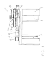
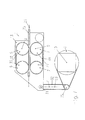
Fig.1 shows a front view of a cable transport device according to the invention in a first embodiment according topatent claim 1. -
Fig.2 shows a plan view ofFig.1 in a 90° pivot position. -
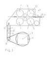
Fig.3 shows a schematic diagram of a front view of a cable transport device according to the invention in a second embodiment according to patent claim 2 in a 90° pivot position. -
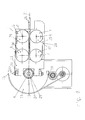
Fig.4 shows a schematic diagram of a back view ofFig.3 . -
Fig.5 shows a schematic diagram of the device according to the invention for regulating the pressure for cable draw-in, -
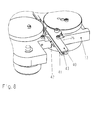
Fig.6 shows a plan view ofFig.1 in a 90° pivot position in a further embodiment. -
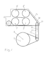
Fig.7 shows a schematic diagram of a front view similar toFig.3 and an embodiment according toFig.6 . -
Fig.8 shows a diagram of a guide sleeve according to the invention in plate design for a cable. -
Fig.9 shows a schematic diagram of a first variant of a divided, adjustable guide sleeve. -
Fig.10 shows a schematic diagram of a second variant of a divided adjustable guide sleeve. - The cable transport device according to
Figures 1 ,2 and6 has a pivotably mountedcable transporter 1 for acable 21 to be drawn in and to be transported, and a first drive means 3 connected in a stationary manner to a base frame 2 and intended for achieving an exactly defined pivot movement of thecable transporter 1 about apivot axis 4. A second drive means 5 ensures synchronous driving of two cooperatingpressure rollers 6 with two cooperatingpressure rollers 7, whoseaxes common pivot axis 4. The twopressure rollers 7 are, as shown inFig.2 , arranged so as to be laterally adjustable. - According to the invention, the second drive means 5 with its
drive axle 10 is connected in a stationary manner to the base frame 2. Thedrive axle 10 of the second drive means 5 for thepressure rollers cable transporter 1, coincides with thepivot axis 4 for thecable transporter 1. - In the embodiments of the invention according to
Figures 1 ,2 and6 , asemicircular pivot plate 11 is mounted horizontally around thepivot axis 4. Thesemicircular pivot plate 11 is connected via the rotary bearing of thepitch axis 31 to abase plate 13 of thecable transporter 1. In each case oneend toothed belt 16 is held on the two outsides of thesemicircular pivot plate 11 by clamping in a stationary manner, thetoothed belt 16 being led directly from itsfirst end 14 via adeflection belt sprocket 17 and adrive belt sprocket 19 mounted on afirst drive axle 18 of the drive means 3, via the outer surface of thesemicircular pivot plate 11, to thesecond end 15 of the clamping of thetoothed belt 16. - The cable transport device shown in
Figures 3 ,4 and7 likewise has a pivotably mountedcable transporter 1 for acable 21 to be drawn in and to be transported and a first drive means 3 connected in a stationary manner to the base frame 2 and intended for achieving an exactly defined pivot movement of thecable transporter 1 around thepivot axis 4. In these embodiments, too, the cable transport device has a second drive means 5 for synchronous driving of at least two cooperatingpressure rollers axes common pivot axis 4. Moreover, twopressure rollers 7 are arranged in a laterally adjustable manner, although the adjustability is not shown in the schematic diagrams according toFigures 3 ,4 and7 . - While
Fig.3 shows the front view of the schematic diagram of the cable transport device with fourpressure rollers Fig.3 is shown inFig.4 . According to the invention, according toFigures 3 and4 , the second drive means 5 is likewise connected with adrive axle 10 for thepressure rollers cable transporter 1 in a stationary manner to the base frame 2. While in the embodiments according toFigures 1 ,2 and6 thebase plate 13 is arranged horizontally, thebase plate 13 in the embodiments according toFigures 3 ,4 and7 is oriented vertically. Theaxes common pitch axis 31. The transmission of the pivot movement takes place via atoothed belt 32, which is clamped symmetrically to thecenter 33 of rotation of thepivot axis 4 of the first drive means between a firstintermediate shaft 34 arranged on abase plate 13 of thecable transporter 1 and a secondintermediate shaft 35 fixed to the machine frame. Thepitch axis 31 of thecable transporter 1 is identical to the axis of the firstintermediate shaft 34. - In order to control the pressure on the
cable 21 to be transported, anadjustable plate 20 according toFig.2 is mounted so as to be transversely displaceable relative to thebase plate 13 of thecable transporter 1 for the purpose of adjusting the pressure.Pressure rollers 6 rotating counterclockwise are arranged on thebase plate 13 andpressure rollers 7 rotating clockwise are arranged on theadjustable plate 20, or vice versa. - As further shown in
Fig.2 , twopressure rollers 6 are rotatably mounted on oneaxis 8 of rotation each on thebase plate 13 of thecable transporter 1 and likewise two pressure rollers are rotatably mounted on oneaxis 9 each on theadjustable plate 20, therespective axes pressure rollers pressure rollers 7, and a counter-wheel 23 is arranged between twopressure rollers 6, or vice versa, directly against thecable 21 transported. - Belt sprockets (6', 7') which have a drive connection via a double-sided
toothed belt 25 to a second drive sprocket arranged on thedrive axle 10 of the second drive means 5 are arranged on theaxes pressure rollers Fig.4 ), thetoothed belt 25 transmitting the rotation of thedrive belt sprocket 24 to thepressure rollers 7 arranged on theadjustable plate 20. Thetoothed belt 25 between the belt sprockets (6') of thepressure rollers 6 and the belt sprockets (7') of thepressure roller 7 is clamped diagonally, resulting in the counterclockwise movement of thepressure rollers 6 and the clockwise movement of thepressure rollers 7. - The
base plate 13 of thecable transporter 1 can, according toFig.2 , be mounted together with theadjustable plate 20 on thedrive axle 10 or, according toFigure 3 , on thepitch axis 31 so as to be pivotable together. - For the purpose of inserting the
cable 21 to be transported, theadjustable plate 20 moves away from thebase plate 13 of thecable transporter 1 and, after insertion of thecable 21 between thepressure rollers adjustable plate 20 travels by means of compressed air or by means of the pressure of anothermechanical energy accumulator 28, for example of a pneumatic cylinder, or a spring, to a position in which thepressure rollers cable 21 to be transported. Apressure mechanism 27 controls the pressure on thecable 21 to be transported, by thepressure rollers 7 mounted in a fixed manner on theadjustable plate 20 relative to thepressure rollers 6 mounted on thebase plate 13 of thecable transporter 1. Such a non linear pressure mechanism is shown inFig.5 . Thepressure mechanism 27 consists, according to the invention, of amechanical energy accumulator 28 or a pneumatic cylinder with recuperating spring, which are connected via a displaceably guided connecting part to aneccentric lever 30 displaceably guided on acarriage 29. The lever geometry is chosen so that the pressure likewise decreases with decreasing distance between thepressure rollers - For avoiding forward and return transport of the
cable 21 during the pivot movement, the seconddrive belt sprocket 24, which is responsible for the rotation of thepressure rollers cable transporter 1, rotates in the same direction with the firstdrive belt sprocket 19 of the first drive means 3 via a control.
In a further working example according toFigures 6 and7 , thepressure rollers pressure rollers 6 forming a firstpressure roller pair 36 and twopressure rollers 7 forming a secondpressure roller pair 37, and a firsttoothed belt 38 being tensioned over the firstpressure roller pair 36 and a secondtoothed belt 39 being tensioned over the secondpressure roller pair 37, and the cable being clamped and guided between the first and the secondtoothed belts cable 21 taking place by means of frictional contact. - According to
Fig.8 , thecable transporter 1 has aguide sleeve 26 for thecable 21. Theguide sleeve 26 is composed of agrooved plate 41 and acover plate 40. These plates can be replaced for adaptation to different cable diameters and for correction of the position of thecable 21 and are equipped for this purpose with different groove geometries. - In addition, the
cover plate 40 and/or thegrooved plate 41 may have openings which permit a cable inscriber, e.g. a printer, access to thecables 21. -
Fig.9 and Fig.10 show that theguide sleeve 26 is formed from two channel elements, afirst channel element 44 being fixed to thebase plate 13 of thecable transporter 1 and asecond channel element 45 being fixed to theadjustable plate 20. Aguide channel 43 which is adapted to the respective cable in width is formed by the distance between base plate and adjustable plate, which distance is determined by the cable. - Alternatively, the
first channel element 44 is fixed on theadjustable plate 20 and thesecond channel element 45 is fixed on thebase plate 13 of thecable transporter 1. - The
adjustable plate 20 andbase plate 13 of thecable transporter 1 move relative to one another so that both can also be moved onto thecable 21. - It is within the scope of the invention to use one
pressure roller pressure rollers - It is also within the scope of the invention for the measuring wheel 22 and the counter-wheel 23 to be arranged upstream or downstream of the
pressure rollers Figures 6 and/or 7. - It is also within the scope of the invention if a pressure mechanism differing from the disclosure is used.
-
- 1
- - Cable transporter
- 2
- - Base frame
- 3
- - First drive means
- 4
- - Pivot axis
- 5
- - Second drive means
- 6
- - Pressure rollers, counterclockwise, arranged on the
base plate 13 - 6'
- - Belt sprocket
- 7
- - Pressure rollers, clockwise, arranged on the
adjustable plate 20 - 7'
- - Belt sprocket
- 8
- - Axis of rotation of the
pressure rollers 6 - 9
- - Axis of rotation of the
pressure rollers 7 - 10
- - Drive axle of the second drive means 5
- 11
- - Semicircular pivot plate
- 12
- - Straight lateral surface
- 13
- - Base plate of the
cable transporter 1 - 14
- - First end of the
toothed belt 16 - 15
- - Second end of the
toothed belt 16 - 16
- - Toothed belt
- 17
- - Deflection belt sprocket
- 18
- - First drive axle of the first drive means 3
- 19
- - Drive sprocket of the first drive means 3
- 20
- - Adjustable plate
- 21
- - Cable
- 22
- - Measuring wheel
- 23
- - Counter-wheel
- 24
- - Drive belt sprocket of the second drive means 5
- 25
- - Toothed belt
- 26
- - Guide sleeve
- 27
- - Pressure mechanism
- 28
- - Mechanical energy accumulator, e.g. pneumatic cylinder, or spring
- 29
- - Carriage
- 30
- - Eccentric
- 31
- - Pitch axis
- 32
- - Toothed belt
- 33
- - Center of rotation
- 34
- - First intermediate shaft, top
- 35
- - Second intermediate shaft, bottom
- 36
- - First pressure roller pair
- 37
- - Second pressure roller pair
- 38
- - First toothed belt
- 39
- - Second toothed belt
- 40
- - Cover plate
- 41
- - Grooved plate
- 42
- - Holder
- 43
- - Guide channel
- 44
- - First channel element
- 45
- - Second channel element
Claims (18)
- Cable transport device having- a pivotably mounted cable transporter (1) for a cable (21) to be drawn in and to be transported,- a first drive means (3) connected in a stationary manner to a base frame (2) and intended for achieving an exactly defined pivot movement of the cable transporter (1) around a pivot axis (4) and- a second drive means (5) for synchronously driving at least two cooperating pressure rollers (6, 7) whose axes (8, 9) of rotation are parallel to one another and parallel to the common pivot axis (4), at least one pressure roller (7) being arranged so as to be laterally adjustable, whereby- the second drive means (5) with a drive axle (10) for the pressure rollers (6, 7) of the cable transporter (1) is connected in a stationary manner to the base frame (2) and characterized by- that the drive axle (10) of the second drive means (5) coincides with the pivot axis (4) for the cable transporter (1).
- Cable transport device having- a pivotably mounted cable transporter (1) for a cable (21) to be drawn in and to be transported,- a first drive means (3) connected in a stationary manner to a base frame (2) and intended for achieving an exactly defined pivot movement of the cable transporter (1) around a pivot axis (4) and- a second drive means (5) for synchronously driving at least two cooperating pressure rollers (6, 7) with axes (8, 9) of rotation, at least one pressure roller (7) being arranged so as to be laterally displaceable, whereby- the second drive means (5) having a drive axle (10) for the pressure rollers (6, 7) of the cable transporter (1) is connected in a stationary manner to the base frame (2),- that the axes (8, 9) of rotation are parallel to one another and parallel to a common pitch axis (31) and
characterized by- that the transmission of the pivot movement takes place via a toothed belt (32) which is tensioned symmetrically to the centre (33) of rotation of the pivot axis (4) of the first drive means between a first intermediate shaft (34) arranged on a base plate (13) of the cable transporter (1) and a second intermediate shaft (35) fixed to the machine frame, the pitch axis (31) of the cable transporter (1) being identical to the axis of the first intermediate shaft (34). - Cable transport device according to claims 1 or 2, characterized in that at least two pressure rollers (6) are rotatably mounted on the base plate (13) of the cable transporter (1) on one axis (8) of rotation each and in that at least two pressure rollers (7) are likewise rotatably mounted on an adjustable plate (20) on one axis (9) of rotation each, the respective axes (8, 9) of rotation of the pressure rollers (6, 7) being arranged opposite one another, and that, between two pressure rollers (7), a measuring wheel (22) for measuring the required cable length rests directly against the transported cable and, between two pressure rollers (6), a counter-wheel (23) rests directly against the transported cable, or vice versa.
- Cable transport device according to any of the preceding claims, characterized in that belt sprockets (6', 7') which have a drive connection via a double-sided toothed belt (25) to a second drive belt sprocket (24) arranged on the drive axle (10) of the second drive means (5) are arranged on the axes (8, 9) of rotation of the pressure rollers (6, 7) on the underside of the cable transporter (1), the toothed belt (25) transmitting the rotation of the drive belt sprocket (24) to the pressure rollers (7) arranged on the adjustable plate (20) and that the toothed belt (25) is clamped diagonally between the belt sprockets (6') of the pressure rollers (6) and the belt sprockets (7') of the pressure rollers (7), resulting in the counter clockwise movement of the pressure rollers (6) and the clockwise movement of the pressure rollers (7).
- Cable transport device according to any of the preceding claims, characterized in that the adjustable plate (20) moves away from the base plate (13) of the cable transporter (1) for the purpose of inserting the cable (21) to be transported and, after insertion of the cable (21) between the pressure rollers (6, 7), the adjustable plate (20) moves by means of compressed air or by means of the pressure of a mechanical energy accumulator (28) to a position in which the pressure rollers (6, 7) and the measuring wheel (22) and the counter-wheel (23) press with a defined force onto the cable (21) to be transported and that the base plate (13) of the cable transporter (1) together with the adjustable plate (20) on the drive axle (10) and/or on the pitch axis (31) are mounted so as to be pivotable together.
- Cable transport device according to any of the preceding claims, characterized in that a pressure mechanism (27) controls the pressure on the cable (21) to be transported, by the pressure rollers (7) mounted in a fixed manner on the adjustable plate (20) relative to the pressure rollers (6) mounted on the base plate (13) of the cable transporter (1).
- Cable transport device according to claim 6, characterized in that the pressure mechanism (27) consists of a pneumatic cylinder with recuperating spring or a pressure spring which is connected via a displaceably guided connecting part to an eccentric lever (30), the lever geometry being chosen so that the pressure likewise decreases with decreasing distance between the pressure rollers (6, 7).
- Cable transport device according to any of the claims 4 and 5 to 7 when dependent on claim 4, characterized in that, for avoiding forward and backward transport of the cable (21) during the pivot movement, the second drive belt sprocket (24), which is responsible for the rotation of the pressure rollers (6, 7) of the cable transporter (1), concomitantly rotates in the same direction with a first drive belt sprocket (19) of the first drive means (3) via a control.
- Cable transport device according to any of the claims 1 to 3 and 5 to 8, characterized in that the pressure rollers (6, 7) are in the form of belt sprockets, two pressure rollers (6) forming a first pressure roller pair (36) and two pressure rollers (7) forming a second pressure roller pair (37), and a first toothed belt (38) being tensioned over the first pressure roller pair (36) and a second toothed belt (39) being tensioned over the second pressure roller pair (37), and the cable being clamped and guided between the first and the second toothed belts (38, 39) and the transport of the cable (21) being effected by means of frictional contact.
- Cable transport device according to any of the preceding claims characterized in, that the cable transport device has a guide sleeve (26) for the cable (21), and that the guide sleeve (26) is composed of a grooved plate (41) and a cover plate (40) and that these plates can be replaced for adaptation to different cable diameters and for correction of the position of the cable (21) and are equipped for this purpose with different groove geometries.
- Cable transport device according to claim 10, characterized in that the cover plate (40) and/or the grooved plate (41) have openings which permit a cable inscriber access to the cables (21).
- Cable transport device according to any of the claims 3 to 9, characterized in that the cable transport device has a guide sleeve (26) for the cable (21), the guide sleeve (26) being formed from two channel elements, a first channel element (44) being fixed to the base plate (13) of the cable transporter (1) and a second channel element (45) being fixed to the adjustable plate (20), a guide channel (43) which is adapted to the respective cable in width being formed by the distance between base plate and adjustable plate, which distance is determined by the cable.
- Cable transport device according to any of the claims 3 to 9, characterized in that the cable transport device has a guide sleeve (26) for the cable (21), the guide sleeve (26) being formed from two channel elements, a first channel element (44) being fixed to the adjustable plate (20) and a second channel element (45) being fixed to the base plate (13) of the cable transporter, a guide channel (43) which is adapted to the respective cable in width being formed by the distance between base plate and adjustable plate, which distance is determined by the cable.
- Cable transport device according to claims 12 and 13, characterized in that the adjustable plate (20) and the base plate (13) of the cable transporter (1) move relative to one another, i.e. both can also be moved onto the cable (21).
- Cable transport device according to any of the preceding claims, characterized in that the base plate (13) of the cable transporter (1) is connected to the pivot axis (4) via a semicircular pivot plate (11) and the rotary bearing of a pitch axis (31), the pitch axis (31) intersecting the pivot axis (4).
- Cable transport device according to claim 15, characterized in that a semicircular pivot plate (11) is mounted horizontally around the pivot axis (4), the semicircular pivot plate (11) being connected via the rotary bearing of the pitch axis (31) to the base plate (13) of the cable transporter (1).
- Cable transport device according to any of the claims 1 to 14, characterized in that a semicircular pivot plate (11) is mounted horizontally around the pivot axis (4), the semicircular pivot plate (11) being connected via the rotary bearing of a pitch axis (31) to the base plate (13) of the cable transporter (1), and that in each case one end (14, 15) of a toothed belt (16) is held on the two outsides of the semicircular pivot plate (11) by clamping in a stationary manner, the toothed belt (16) being led directly from its first end (14) via a deflection belt sprocket (17) and a drive belt sprocket (19) mounted on a first drive axle (18) of the drive means (3), via the outer surface of the semicircular pivot plate (11), to the second end (15) of the clamping of the toothed belt (16).
- Cable transport device according to claim 17, characterized in that the pitch axis (31) intersects the pivot axis (4).
Priority Applications (1)
| Application Number | Priority Date | Filing Date | Title |
|---|---|---|---|
| PL09750251T PL2291317T3 (en) | 2008-05-20 | 2009-05-20 | Cable transport device |
Applications Claiming Priority (3)
| Application Number | Priority Date | Filing Date | Title |
|---|---|---|---|
| CH7572008 | 2008-05-20 | ||
| US11718908P | 2008-11-23 | 2008-11-23 | |
| PCT/IB2009/052125 WO2009141794A2 (en) | 2008-05-20 | 2009-05-20 | Cable transport device |
Publications (2)
| Publication Number | Publication Date |
|---|---|
| EP2291317A2 EP2291317A2 (en) | 2011-03-09 |
| EP2291317B1 true EP2291317B1 (en) | 2016-01-06 |
Family
ID=40093032
Family Applications (1)
| Application Number | Title | Priority Date | Filing Date |
|---|---|---|---|
| EP09750251.2A Active EP2291317B1 (en) | 2008-05-20 | 2009-05-20 | Cable transport device |
Country Status (11)
| Country | Link |
|---|---|
| US (2) | US20110049211A1 (en) |
| EP (1) | EP2291317B1 (en) |
| JP (1) | JP5528433B2 (en) |
| KR (1) | KR101569544B1 (en) |
| CN (1) | CN102036895B (en) |
| BR (1) | BRPI0912745A2 (en) |
| CA (1) | CA2724421A1 (en) |
| ES (1) | ES2564084T3 (en) |
| MX (1) | MX2010012083A (en) |
| PL (1) | PL2291317T3 (en) |
| WO (1) | WO2009141794A2 (en) |
Families Citing this family (31)
| Publication number | Priority date | Publication date | Assignee | Title |
|---|---|---|---|---|
| CA2724421A1 (en) | 2008-05-20 | 2009-11-26 | Schleuniger Holding Ag | Cable transport device |
| CN102195226B (en) * | 2010-03-12 | 2014-09-03 | 库迈思控股股份公司 | Cable supplying and rotating system |
| ITTO20110288A1 (en) * | 2011-03-31 | 2012-10-01 | Cometo S N C | POWER SUPPLY UNIT FOR WIRES OR CABLES, IN PARTICULAR FOR WIRES OR CABLES |
| CN104053620B (en) * | 2011-11-11 | 2017-05-03 | 施洛伊尼格控股有限公司 | Line transport device |
| ES2582331T3 (en) | 2011-11-11 | 2016-09-12 | Schleuniger Holding Ag | Line Conveyor Device |
| JP6072054B2 (en) | 2011-11-11 | 2017-02-01 | シュロニガー ホールディング アーゲー | Cable receiving device (wire stacker) |
| EP2777053B1 (en) | 2011-11-11 | 2015-12-30 | Schleuniger Holding AG | Twisting device |
| CN103022854B (en) * | 2012-12-31 | 2015-08-19 | 慈溪市宏晟机械设备有限公司 | A kind of automatic tangent peeling loose end press |
| EP2801984B1 (en) | 2013-05-08 | 2018-11-14 | Schleuniger Holding AG | Gripper, twisting head and twisting head device |
| CN104030082B (en) * | 2014-06-19 | 2017-02-15 | 国网四川省电力公司成都市新都供电分公司 | High-power cable output machine |
| CN104930997A (en) * | 2015-06-28 | 2015-09-23 | 无锡锡洲电磁线有限公司 | Enameled flat wire online detection device |
| EP3165487A1 (en) * | 2015-11-08 | 2017-05-10 | Schleuniger Holding AG | Conduit transportation device, in particular for cables to be processed in cable processing machines |
| CN105977751A (en) * | 2016-05-19 | 2016-09-28 | 李传慧 | Intelligent wire grooved wheel trimming machine |
| US10003183B2 (en) | 2016-09-01 | 2018-06-19 | Terrapower, Llc | Cable management systems |
| CN106253023A (en) * | 2016-10-05 | 2016-12-21 | 王杨 | Formula periodically sheave electric wire finishing machine turned round by a kind of gripping slide rail that swings |
| CN109279444B (en) * | 2018-01-25 | 2023-12-26 | 成都九系机器人科技有限公司 | Automatic winding displacement equipment |
| RS61477B1 (en) * | 2018-03-23 | 2021-03-31 | Komax Holding Ag | Cable processing machine with movable guiding elements and method of inserting a cable into a cable processing machine |
| US11196238B2 (en) * | 2018-07-11 | 2021-12-07 | Schleuniger Ag | Device for detecting contact with an electrical conductor, method for identifying contact with an electrical conductor, insulation stripping machine comprising a device of this kind |
| CN109290243B (en) * | 2018-09-29 | 2020-12-22 | 天长市运成电缆辅料有限公司 | Efficient cleaning device for cable recovery |
| EP3648270A1 (en) * | 2018-11-02 | 2020-05-06 | Komax Holding Ag | Cable treating device |
| IT201900001845A1 (en) | 2019-02-08 | 2020-08-08 | Tesmec Spa | CABLE RECOVERY MACHINE |
| IT201900001841A1 (en) * | 2019-02-08 | 2020-08-08 | Tesmec Spa | CABLE RECOVERY MACHINE |
| US11258223B1 (en) | 2019-08-15 | 2022-02-22 | Design Ready Controls, Inc. | Automated flexible strand feeder assembly |
| CN110759166B (en) * | 2019-10-29 | 2022-08-26 | 国网山东省电力公司聊城供电公司 | Speed-adjustable cable rack for bypass operation of power distribution network |
| CN112758770B (en) * | 2021-01-20 | 2022-09-16 | 河南省鼎鼎实业有限公司 | Reinforcing bar production is with feeding location guider |
| CN112897210B (en) * | 2021-03-01 | 2022-01-04 | 陈旭军 | Communication cable's book covers device |
| US11766699B1 (en) * | 2021-06-24 | 2023-09-26 | Amazon Technologies, Inc. | Interconnected sortation systems with multiple inputs and destinations |
| CN113562534B (en) * | 2021-07-29 | 2023-07-21 | 福建省顺天亿建设有限公司 | Tool conveying device for engineering building and use method |
| CN113872004A (en) * | 2021-09-07 | 2021-12-31 | 和田工业精密电子(常熟)有限公司 | On-vehicle connector metal terminal assembly devices |
| CN115583534B (en) * | 2022-10-31 | 2024-04-05 | 华能澜沧江水电股份有限公司 | Cable pulling and winding device |
| KR102546785B1 (en) * | 2023-02-08 | 2023-06-22 | 주식회사 크린텍 | apparatus for controlling cable |
Family Cites Families (61)
| Publication number | Priority date | Publication date | Assignee | Title |
|---|---|---|---|---|
| US831729A (en) * | 1906-01-04 | 1906-09-25 | Ernest B Merry | Cable-gripper. |
| NL262283A (en) | 1962-05-09 | 1900-01-01 | ||
| US3198220A (en) * | 1962-12-07 | 1965-08-03 | Bendix Corp | Twisting machine for stranded wire |
| US3540110A (en) * | 1968-04-12 | 1970-11-17 | Thomas & Betts Corp | Guide device |
| US3839777A (en) * | 1973-10-26 | 1974-10-08 | E Puzio | Wire guide assembly |
| US4095497A (en) * | 1977-04-06 | 1978-06-20 | Gte Sylvania Incorporated | Article handling apparatus |
| EP0007473B1 (en) * | 1978-07-28 | 1982-01-13 | Siemens Aktiengesellschaft | Device for sz stranding power current cable cores with a sector-shaped conductor cross-section |
| CH660093A5 (en) * | 1982-12-03 | 1987-03-13 | Megomat Ag | CABLE ASSEMBLY MACHINE. |
| US4655107A (en) * | 1984-05-04 | 1987-04-07 | Bernhard Juergenhake | Transport system for an automatic cable processing machine |
| DE3630359A1 (en) | 1986-09-05 | 1988-03-17 | Dunkel Otto Gmbh | Magazine for supplying an automatic pin setting machine for flat cable connectors |
| CH673858A5 (en) | 1986-12-03 | 1990-04-12 | Megomat Ag | Cable sections make-up set - consisting of two grippers, two auxiliary grippers, and cutting stripping unit for cable press |
| US5010797A (en) * | 1987-06-30 | 1991-04-30 | Jiri Stepan | Arrangement for cutting and/or stripping apparatuses |
| EP0303724A1 (en) | 1987-08-19 | 1989-02-22 | Hans Hackner | Apparatus for cutting and stripping wires and for applying crimp, plug and screw terminals, as well as for manufacturing chain structures |
| DD292103A5 (en) | 1990-02-19 | 1991-07-18 | Kabelwerk Plauen,De | RECEPTACLE DEVICE FOR THE MANUFACTURE OF ELECTRICALLY TRANSMITTED CABLES |
| US5350101A (en) * | 1990-11-20 | 1994-09-27 | Interventional Technologies Inc. | Device for advancing a rotatable tube |
| EP0496049B1 (en) * | 1991-01-21 | 1995-05-17 | Ttc Technology Trading Company | Improvement to the device for feeding a cable into an automatic cable manufacturing machine |
| GB9107431D0 (en) * | 1991-04-09 | 1991-05-22 | British Aerospace | Cable handling and preparation apparatus |
| EP0525364A1 (en) * | 1991-08-01 | 1993-02-03 | Löhr & Herrmann GmbH | Device for storing and transporting circuit boards with delicate surfaces |
| SE500526C2 (en) | 1991-09-25 | 1994-07-11 | Peter Hoyaukin | Method and apparatus for feeding straight wire sections to a fixed position and a web-shaped material for use in the method |
| CH684374A5 (en) * | 1992-11-17 | 1994-08-31 | Komax Holding Ag | Kabelzuführungs- and -wechseleinrichtung for a wire processing machine. |
| US5650181A (en) * | 1993-06-17 | 1997-07-22 | Kotaki; Daizo | Injection molding die for producing plastic filter |
| US5497928A (en) * | 1994-05-12 | 1996-03-12 | Rockford Manufacturing Group, Inc. | Apparatus for feeding wire having a linearly movable roller pinch pair with guide rod |
| CH689278A5 (en) * | 1994-10-21 | 1999-01-29 | Komax Holding Ag | Kabeltransport- and pivoting device. |
| KR100284380B1 (en) * | 1995-01-30 | 2001-03-02 | 사이카와 시코오 | Wire processing device |
| US6910256B2 (en) * | 1995-11-06 | 2005-06-28 | Schleuniger Holding Ag | Continuous cable processing apparatus |
| EP0788200B1 (en) | 1996-01-30 | 2007-01-03 | komax Holding AG | Device for laying cables |
| US5820008A (en) * | 1996-01-31 | 1998-10-13 | The Whitaker Corporation | Machine for processing electrical wires having improved wire guide |
| DE19624973A1 (en) | 1996-06-22 | 1998-01-02 | Telegaertner Geraetebau Gmbh | Electrical cable sections automated handling method e.g. for manufacturing cable looms/harnesses |
| DE19631770C2 (en) * | 1996-08-06 | 1998-08-27 | Gluth Systemtechnik Gmbh | Method for twisting at least two individual lines |
| AU4234397A (en) * | 1996-08-30 | 1998-03-19 | Whitaker Corporation, The | Wire feed and positioning unit |
| US5816384A (en) * | 1996-11-04 | 1998-10-06 | Hsu; Chiu-Lin | Cut type wire receiver |
| JP4085185B2 (en) * | 1997-02-14 | 2008-05-14 | モレックス インコーポレーテッド | Wire length measuring device in multi-electric harness manufacturing equipment |
| CH691682A5 (en) * | 1997-03-10 | 2001-09-14 | Komax Holding Ag | Cable transport unit. |
| JP3409643B2 (en) | 1997-06-05 | 2003-05-26 | 住友電装株式会社 | Twisted wire manufacturing equipment |
| US6135164A (en) | 1997-09-29 | 2000-10-24 | Komax Holding Ag | Apparatus and method for preparing wires in a harness making machine |
| FI103613B (en) * | 1998-03-26 | 1999-07-30 | Nextrom Holding Sa | Device in belt draw device |
| EP0984530B1 (en) | 1998-08-31 | 2007-05-30 | komax Holding AG | Device for bringing conductors together |
| JP2000173368A (en) * | 1998-12-09 | 2000-06-23 | Harness Syst Tech Res Ltd | Wire harness manufacturing device |
| EP1032095B1 (en) | 1999-02-23 | 2013-05-22 | Komax Holding AG | Method and device for processing and twisting a conductor pair |
| US6289944B1 (en) * | 1999-02-23 | 2001-09-18 | Komax Holding Ag | Method and equipment for the treatment and twisting together of a conductor pair |
| DE50102842D1 (en) | 2000-12-08 | 2004-08-19 | Komax Holding Ag Dierikon | Cable processing device with cable changer |
| EP1213800B1 (en) | 2000-12-08 | 2004-07-14 | Komax Holding Ag | Cable processing assembly with cable changer |
| DE10107670B4 (en) | 2001-02-19 | 2005-11-10 | Gluth Systemtechnik Gmbh | Method and device for twisting at least two individual lines |
| SE519712C2 (en) * | 2001-03-22 | 2003-04-01 | Ericsson Telefon Ab L M | Optical fiber feeding method and apparatus |
| EP1387449B1 (en) * | 2002-07-22 | 2005-04-27 | komax Holding AG | Apparatus and method for coiling of cable material |
| JP2004071237A (en) * | 2002-08-02 | 2004-03-04 | Yazaki Corp | Wire crimping device |
| JP4216154B2 (en) * | 2003-02-04 | 2009-01-28 | 新明和工業株式会社 | Electric wire processing machine |
| EP1447888B1 (en) * | 2003-02-17 | 2014-12-10 | Komax Holding AG | Gripper for a cable treating device |
| CN100399648C (en) * | 2003-09-19 | 2008-07-02 | 新明和工业株式会社 | Wire process machine |
| DE502006000776D1 (en) * | 2005-02-11 | 2008-07-03 | Komax Holding Ag | Method and device for processing a cable |
| CN201044320Y (en) * | 2007-05-08 | 2008-04-02 | 倪君权 | Full-automatic crimping machine tread mechanism |
| CA2724421A1 (en) | 2008-05-20 | 2009-11-26 | Schleuniger Holding Ag | Cable transport device |
| CH700897B1 (en) | 2009-04-24 | 2014-02-14 | Schleuniger Holding Ag | Apparatus and method for merging conductors for producing a double crimp. |
| US20120204792A1 (en) | 2009-11-06 | 2012-08-16 | Schleuniger Holding Ag | Cable inscription device and method for inscribing cables |
| CN201594421U (en) | 2009-12-04 | 2010-09-29 | 富港电子(东莞)有限公司 | Automatic wire cutting and stranding machine |
| EP2777053B1 (en) | 2011-11-11 | 2015-12-30 | Schleuniger Holding AG | Twisting device |
| JP6072054B2 (en) | 2011-11-11 | 2017-02-01 | シュロニガー ホールディング アーゲー | Cable receiving device (wire stacker) |
| CN104053620B (en) | 2011-11-11 | 2017-05-03 | 施洛伊尼格控股有限公司 | Line transport device |
| WO2013068981A1 (en) | 2011-11-11 | 2013-05-16 | Schleuniger Holding Ag | Twisting head and twisting device |
| ES2582331T3 (en) | 2011-11-11 | 2016-09-12 | Schleuniger Holding Ag | Line Conveyor Device |
| EP2801984B1 (en) | 2013-05-08 | 2018-11-14 | Schleuniger Holding AG | Gripper, twisting head and twisting head device |
-
2009
- 2009-05-20 CA CA2724421A patent/CA2724421A1/en not_active Abandoned
- 2009-05-20 BR BRPI0912745A patent/BRPI0912745A2/en not_active IP Right Cessation
- 2009-05-20 ES ES09750251.2T patent/ES2564084T3/en active Active
- 2009-05-20 WO PCT/IB2009/052125 patent/WO2009141794A2/en active Application Filing
- 2009-05-20 PL PL09750251T patent/PL2291317T3/en unknown
- 2009-05-20 KR KR1020107024792A patent/KR101569544B1/en active IP Right Grant
- 2009-05-20 MX MX2010012083A patent/MX2010012083A/en active IP Right Grant
- 2009-05-20 CN CN2009801179355A patent/CN102036895B/en active Active
- 2009-05-20 US US12/990,116 patent/US20110049211A1/en not_active Abandoned
- 2009-05-20 JP JP2011510082A patent/JP5528433B2/en active Active
- 2009-05-20 EP EP09750251.2A patent/EP2291317B1/en active Active
-
2014
- 2014-12-31 US US14/587,495 patent/US9475669B2/en active Active
Also Published As
| Publication number | Publication date |
|---|---|
| BRPI0912745A2 (en) | 2015-10-13 |
| EP2291317A2 (en) | 2011-03-09 |
| MX2010012083A (en) | 2010-12-07 |
| CN102036895B (en) | 2012-10-24 |
| US9475669B2 (en) | 2016-10-25 |
| KR20110011610A (en) | 2011-02-08 |
| WO2009141794A3 (en) | 2010-12-29 |
| WO2009141794A2 (en) | 2009-11-26 |
| CN102036895A (en) | 2011-04-27 |
| KR101569544B1 (en) | 2015-11-16 |
| WO2009141794A4 (en) | 2011-02-24 |
| CA2724421A1 (en) | 2009-11-26 |
| PL2291317T3 (en) | 2016-06-30 |
| JP2011523391A (en) | 2011-08-11 |
| ES2564084T3 (en) | 2016-03-17 |
| US20150115013A1 (en) | 2015-04-30 |
| JP5528433B2 (en) | 2014-06-25 |
| US20110049211A1 (en) | 2011-03-03 |
Similar Documents
| Publication | Publication Date | Title |
|---|---|---|
| EP2291317B1 (en) | Cable transport device | |
| CA2645172C (en) | Stamping apparatus with feed device | |
| US20150008245A1 (en) | Line transport device | |
| US6533104B1 (en) | Device for receiving and transporting objects | |
| US9265261B2 (en) | Oven transfer apparatus with laterally displaceable conveyor belt | |
| EP2511213B1 (en) | Transport system for transporting a cable | |
| JP6358849B2 (en) | Feeder for wireless binding machine and wireless binding machine | |
| US5188213A (en) | Apparatus for transporting cable lengths or sections | |
| US7249993B2 (en) | Machining apparatus for skis having a binding | |
| CZ52989A3 (en) | Device for producing flaky paste | |
| US7124877B2 (en) | Method and device for the conversion of a conveyed stream of flat articles | |
| CN218602491U (en) | Feeding mechanism, feeding device and winding equipment | |
| CN218602517U (en) | Feeding device and winding equipment | |
| CN109128846B (en) | Pipe fitting production facility | |
| US6158940A (en) | Device for the back rounding of book blocks | |
| CN116247266A (en) | Feeding device, winding equipment and winding method | |
| WO2013001163A1 (en) | Method and apparatus for transferring a leader from a first processing apparatus to a second processing apparatus | |
| KR101587229B1 (en) | Apparatus for transferring trapezoid wire | |
| KR100413064B1 (en) | apparatus for folding arc-shaped band blade | |
| CN117161597B (en) | Welding production line of strip steel for automobile | |
| KR20190063399A (en) | Substrate conveying apparatus and substrate processing apparatus | |
| CN216834455U (en) | Automatic edge bonding machine | |
| CN111989220A (en) | Drive device for stamping foil, stamping station and stamping machine and method for controlling drive of stamping foil | |
| EP0201120B2 (en) | Device to feed a multiple-feed straightening machine automatically downstream of a cooling plate | |
| JP2008004556A (en) | Cable-measuring device in electric wire processing machine |
Legal Events
| Date | Code | Title | Description |
|---|---|---|---|
| PUAI | Public reference made under article 153(3) epc to a published international application that has entered the european phase |
Free format text: ORIGINAL CODE: 0009012 |
|
| AK | Designated contracting states |
Kind code of ref document: A2 Designated state(s): AT BE BG CH CY CZ DE DK EE ES FI FR GB GR HR HU IE IS IT LI LT LU LV MC MK MT NL NO PL PT RO SE SI SK TR |
|
| AX | Request for extension of the european patent |
Extension state: AL BA RS |
|
| RIC1 | Information provided on ipc code assigned before grant |
Ipc: H01R 43/052 20060101ALI20110310BHEP Ipc: H01R 43/058 20060101ALI20110310BHEP Ipc: B65H 51/10 20060101AFI20110310BHEP Ipc: B65H 51/32 20060101ALI20110310BHEP Ipc: B65H 57/04 20060101ALI20110310BHEP |
|
| 17P | Request for examination filed |
Effective date: 20110629 |
|
| RBV | Designated contracting states (corrected) |
Designated state(s): AT BE BG CH CY CZ DE DK EE ES FI FR GB GR HR HU IE IS IT LI LT LU LV MC MK MT NL NO PL PT RO SE SI SK TR |
|
| DAX | Request for extension of the european patent (deleted) | ||
| 17Q | First examination report despatched |
Effective date: 20131210 |
|
| GRAP | Despatch of communication of intention to grant a patent |
Free format text: ORIGINAL CODE: EPIDOSNIGR1 |
|
| INTG | Intention to grant announced |
Effective date: 20150819 |
|
| GRAS | Grant fee paid |
Free format text: ORIGINAL CODE: EPIDOSNIGR3 |
|
| GRAA | (expected) grant |
Free format text: ORIGINAL CODE: 0009210 |
|
| AK | Designated contracting states |
Kind code of ref document: B1 Designated state(s): AT BE BG CH CY CZ DE DK EE ES FI FR GB GR HR HU IE IS IT LI LT LU LV MC MK MT NL NO PL PT RO SE SI SK TR |
|
| REG | Reference to a national code |
Ref country code: GB Ref legal event code: FG4D |
|
| REG | Reference to a national code |
Ref country code: CH Ref legal event code: EP |
|
| REG | Reference to a national code |
Ref country code: IE Ref legal event code: FG4D |
|
| REG | Reference to a national code |
Ref country code: AT Ref legal event code: REF Ref document number: 768661 Country of ref document: AT Kind code of ref document: T Effective date: 20160215 Ref country code: CH Ref legal event code: NV Representative=s name: ROSENICH PAUL; KUENSCH JOACHIM PATENTBUERO PAU, LI |
|
| REG | Reference to a national code |
Ref country code: DE Ref legal event code: R096 Ref document number: 602009035612 Country of ref document: DE |
|
| REG | Reference to a national code |
Ref country code: ES Ref legal event code: FG2A Ref document number: 2564084 Country of ref document: ES Kind code of ref document: T3 Effective date: 20160317 |
|
| REG | Reference to a national code |
Ref country code: PT Ref legal event code: SC4A Free format text: AVAILABILITY OF NATIONAL TRANSLATION Effective date: 20160330 |
|
| REG | Reference to a national code |
Ref country code: LT Ref legal event code: MG4D |
|
| REG | Reference to a national code |
Ref country code: NL Ref legal event code: MP Effective date: 20160106 |
|
| REG | Reference to a national code |
Ref country code: FR Ref legal event code: PLFP Year of fee payment: 8 |
|
| REG | Reference to a national code |
Ref country code: AT Ref legal event code: MK05 Ref document number: 768661 Country of ref document: AT Kind code of ref document: T Effective date: 20160106 |
|
| PG25 | Lapsed in a contracting state [announced via postgrant information from national office to epo] |
Ref country code: NL Free format text: LAPSE BECAUSE OF FAILURE TO SUBMIT A TRANSLATION OF THE DESCRIPTION OR TO PAY THE FEE WITHIN THE PRESCRIBED TIME-LIMIT Effective date: 20160106 |
|
| PG25 | Lapsed in a contracting state [announced via postgrant information from national office to epo] |
Ref country code: GR Free format text: LAPSE BECAUSE OF FAILURE TO SUBMIT A TRANSLATION OF THE DESCRIPTION OR TO PAY THE FEE WITHIN THE PRESCRIBED TIME-LIMIT Effective date: 20160407 Ref country code: FI Free format text: LAPSE BECAUSE OF FAILURE TO SUBMIT A TRANSLATION OF THE DESCRIPTION OR TO PAY THE FEE WITHIN THE PRESCRIBED TIME-LIMIT Effective date: 20160106 Ref country code: HR Free format text: LAPSE BECAUSE OF FAILURE TO SUBMIT A TRANSLATION OF THE DESCRIPTION OR TO PAY THE FEE WITHIN THE PRESCRIBED TIME-LIMIT Effective date: 20160106 Ref country code: NO Free format text: LAPSE BECAUSE OF FAILURE TO SUBMIT A TRANSLATION OF THE DESCRIPTION OR TO PAY THE FEE WITHIN THE PRESCRIBED TIME-LIMIT Effective date: 20160406 |
|
| PG25 | Lapsed in a contracting state [announced via postgrant information from national office to epo] |
Ref country code: LV Free format text: LAPSE BECAUSE OF FAILURE TO SUBMIT A TRANSLATION OF THE DESCRIPTION OR TO PAY THE FEE WITHIN THE PRESCRIBED TIME-LIMIT Effective date: 20160106 Ref country code: LT Free format text: LAPSE BECAUSE OF FAILURE TO SUBMIT A TRANSLATION OF THE DESCRIPTION OR TO PAY THE FEE WITHIN THE PRESCRIBED TIME-LIMIT Effective date: 20160106 Ref country code: BE Free format text: LAPSE BECAUSE OF NON-PAYMENT OF DUE FEES Effective date: 20160531 Ref country code: IS Free format text: LAPSE BECAUSE OF FAILURE TO SUBMIT A TRANSLATION OF THE DESCRIPTION OR TO PAY THE FEE WITHIN THE PRESCRIBED TIME-LIMIT Effective date: 20160506 Ref country code: SE Free format text: LAPSE BECAUSE OF FAILURE TO SUBMIT A TRANSLATION OF THE DESCRIPTION OR TO PAY THE FEE WITHIN THE PRESCRIBED TIME-LIMIT Effective date: 20160106 Ref country code: AT Free format text: LAPSE BECAUSE OF FAILURE TO SUBMIT A TRANSLATION OF THE DESCRIPTION OR TO PAY THE FEE WITHIN THE PRESCRIBED TIME-LIMIT Effective date: 20160106 |
|
| REG | Reference to a national code |
Ref country code: DE Ref legal event code: R097 Ref document number: 602009035612 Country of ref document: DE |
|
| PG25 | Lapsed in a contracting state [announced via postgrant information from national office to epo] |
Ref country code: EE Free format text: LAPSE BECAUSE OF FAILURE TO SUBMIT A TRANSLATION OF THE DESCRIPTION OR TO PAY THE FEE WITHIN THE PRESCRIBED TIME-LIMIT Effective date: 20160106 Ref country code: DK Free format text: LAPSE BECAUSE OF FAILURE TO SUBMIT A TRANSLATION OF THE DESCRIPTION OR TO PAY THE FEE WITHIN THE PRESCRIBED TIME-LIMIT Effective date: 20160106 |
|
| PLBE | No opposition filed within time limit |
Free format text: ORIGINAL CODE: 0009261 |
|
| STAA | Information on the status of an ep patent application or granted ep patent |
Free format text: STATUS: NO OPPOSITION FILED WITHIN TIME LIMIT |
|
| PG25 | Lapsed in a contracting state [announced via postgrant information from national office to epo] |
Ref country code: SK Free format text: LAPSE BECAUSE OF FAILURE TO SUBMIT A TRANSLATION OF THE DESCRIPTION OR TO PAY THE FEE WITHIN THE PRESCRIBED TIME-LIMIT Effective date: 20160106 Ref country code: RO Free format text: LAPSE BECAUSE OF FAILURE TO SUBMIT A TRANSLATION OF THE DESCRIPTION OR TO PAY THE FEE WITHIN THE PRESCRIBED TIME-LIMIT Effective date: 20160106 |
|
| 26N | No opposition filed |
Effective date: 20161007 |
|
| PG25 | Lapsed in a contracting state [announced via postgrant information from national office to epo] |
Ref country code: BE Free format text: LAPSE BECAUSE OF FAILURE TO SUBMIT A TRANSLATION OF THE DESCRIPTION OR TO PAY THE FEE WITHIN THE PRESCRIBED TIME-LIMIT Effective date: 20160106 Ref country code: LU Free format text: LAPSE BECAUSE OF FAILURE TO SUBMIT A TRANSLATION OF THE DESCRIPTION OR TO PAY THE FEE WITHIN THE PRESCRIBED TIME-LIMIT Effective date: 20160520 |
|
| GBPC | Gb: european patent ceased through non-payment of renewal fee |
Effective date: 20160520 |
|
| REG | Reference to a national code |
Ref country code: IE Ref legal event code: MM4A |
|
| PG25 | Lapsed in a contracting state [announced via postgrant information from national office to epo] |
Ref country code: SI Free format text: LAPSE BECAUSE OF FAILURE TO SUBMIT A TRANSLATION OF THE DESCRIPTION OR TO PAY THE FEE WITHIN THE PRESCRIBED TIME-LIMIT Effective date: 20160106 Ref country code: BG Free format text: LAPSE BECAUSE OF FAILURE TO SUBMIT A TRANSLATION OF THE DESCRIPTION OR TO PAY THE FEE WITHIN THE PRESCRIBED TIME-LIMIT Effective date: 20160406 |
|
| REG | Reference to a national code |
Ref country code: FR Ref legal event code: PLFP Year of fee payment: 9 |
|
| PG25 | Lapsed in a contracting state [announced via postgrant information from national office to epo] |
Ref country code: IE Free format text: LAPSE BECAUSE OF NON-PAYMENT OF DUE FEES Effective date: 20160520 Ref country code: GB Free format text: LAPSE BECAUSE OF NON-PAYMENT OF DUE FEES Effective date: 20160520 |
|
| REG | Reference to a national code |
Ref country code: FR Ref legal event code: PLFP Year of fee payment: 10 |
|
| PG25 | Lapsed in a contracting state [announced via postgrant information from national office to epo] |
Ref country code: CY Free format text: LAPSE BECAUSE OF FAILURE TO SUBMIT A TRANSLATION OF THE DESCRIPTION OR TO PAY THE FEE WITHIN THE PRESCRIBED TIME-LIMIT Effective date: 20160106 Ref country code: HU Free format text: LAPSE BECAUSE OF FAILURE TO SUBMIT A TRANSLATION OF THE DESCRIPTION OR TO PAY THE FEE WITHIN THE PRESCRIBED TIME-LIMIT; INVALID AB INITIO Effective date: 20090520 |
|
| PG25 | Lapsed in a contracting state [announced via postgrant information from national office to epo] |
Ref country code: MK Free format text: LAPSE BECAUSE OF FAILURE TO SUBMIT A TRANSLATION OF THE DESCRIPTION OR TO PAY THE FEE WITHIN THE PRESCRIBED TIME-LIMIT Effective date: 20160106 Ref country code: MC Free format text: LAPSE BECAUSE OF FAILURE TO SUBMIT A TRANSLATION OF THE DESCRIPTION OR TO PAY THE FEE WITHIN THE PRESCRIBED TIME-LIMIT Effective date: 20160106 Ref country code: MT Free format text: LAPSE BECAUSE OF NON-PAYMENT OF DUE FEES Effective date: 20160531 Ref country code: TR Free format text: LAPSE BECAUSE OF FAILURE TO SUBMIT A TRANSLATION OF THE DESCRIPTION OR TO PAY THE FEE WITHIN THE PRESCRIBED TIME-LIMIT Effective date: 20160106 |
|
| PGFP | Annual fee paid to national office [announced via postgrant information from national office to epo] |
Ref country code: SK Payment date: 20181018 Year of fee payment: 12 Ref country code: PL Payment date: 20190426 Year of fee payment: 11 Ref country code: CZ Payment date: 20190502 Year of fee payment: 11 |
|
| PGFP | Annual fee paid to national office [announced via postgrant information from national office to epo] |
Ref country code: FR Payment date: 20190524 Year of fee payment: 11 |
|
| REG | Reference to a national code |
Ref country code: CH Ref legal event code: PCAR Free format text: NEW ADDRESS: ROTENBODENSTRASSE 12, 9497 TRIESENBERG (LI) |
|
| REG | Reference to a national code |
Ref country code: DE Ref legal event code: R082 Ref document number: 602009035612 Country of ref document: DE Representative=s name: PATENTBUERO PAUL ROSENICH AG, LI Ref country code: DE Ref legal event code: R081 Ref document number: 602009035612 Country of ref document: DE Owner name: SCHLEUNIGER AG, CH Free format text: FORMER OWNER: SCHLEUNIGER HOLDING AG, THUN, CH |
|
| PG25 | Lapsed in a contracting state [announced via postgrant information from national office to epo] |
Ref country code: PT Free format text: LAPSE BECAUSE OF NON-PAYMENT OF DUE FEES Effective date: 20201120 Ref country code: CZ Free format text: LAPSE BECAUSE OF NON-PAYMENT OF DUE FEES Effective date: 20200520 |
|
| REG | Reference to a national code |
Ref country code: CH Ref legal event code: PFA Owner name: SCHLEUNIGER AG, CH Free format text: FORMER OWNER: SCHLEUNIGER HOLDING AG, CH |
|
| PG25 | Lapsed in a contracting state [announced via postgrant information from national office to epo] |
Ref country code: FR Free format text: LAPSE BECAUSE OF NON-PAYMENT OF DUE FEES Effective date: 20200531 |
|
| PGFP | Annual fee paid to national office [announced via postgrant information from national office to epo] |
Ref country code: PL Payment date: 20190426 Year of fee payment: 11 |
|
| REG | Reference to a national code |
Ref country code: ES Ref legal event code: FD2A Effective date: 20211004 |
|
| PG25 | Lapsed in a contracting state [announced via postgrant information from national office to epo] |
Ref country code: ES Free format text: LAPSE BECAUSE OF NON-PAYMENT OF DUE FEES Effective date: 20200521 |
|
| PG25 | Lapsed in a contracting state [announced via postgrant information from national office to epo] |
Ref country code: PL Free format text: LAPSE BECAUSE OF NON-PAYMENT OF DUE FEES Effective date: 20200520 |
|
| P01 | Opt-out of the competence of the unified patent court (upc) registered |
Effective date: 20230606 |
|
| PGFP | Annual fee paid to national office [announced via postgrant information from national office to epo] |
Ref country code: IT Payment date: 20230529 Year of fee payment: 15 Ref country code: DE Payment date: 20230531 Year of fee payment: 15 Ref country code: CH Payment date: 20230602 Year of fee payment: 15 |