EP2291009A1 - Gateway device, method for controlling radio transmission, and radio communication system - Google Patents
Gateway device, method for controlling radio transmission, and radio communication system Download PDFInfo
- Publication number
- EP2291009A1 EP2291009A1 EP08777222A EP08777222A EP2291009A1 EP 2291009 A1 EP2291009 A1 EP 2291009A1 EP 08777222 A EP08777222 A EP 08777222A EP 08777222 A EP08777222 A EP 08777222A EP 2291009 A1 EP2291009 A1 EP 2291009A1
- Authority
- EP
- European Patent Office
- Prior art keywords
- femto
- radio
- base station
- mobile subscriber
- message
- Prior art date
- Legal status (The legal status is an assumption and is not a legal conclusion. Google has not performed a legal analysis and makes no representation as to the accuracy of the status listed.)
- Withdrawn
Links
Images









Classifications
-
- H—ELECTRICITY
- H04—ELECTRIC COMMUNICATION TECHNIQUE
- H04W—WIRELESS COMMUNICATION NETWORKS
- H04W52/00—Power management, e.g. Transmission Power Control [TPC] or power classes
- H04W52/02—Power saving arrangements
- H04W52/0203—Power saving arrangements in the radio access network or backbone network of wireless communication networks
- H04W52/0206—Power saving arrangements in the radio access network or backbone network of wireless communication networks in access points, e.g. base stations
-
- H—ELECTRICITY
- H04—ELECTRIC COMMUNICATION TECHNIQUE
- H04W—WIRELESS COMMUNICATION NETWORKS
- H04W76/00—Connection management
- H04W76/30—Connection release
-
- H—ELECTRICITY
- H04—ELECTRIC COMMUNICATION TECHNIQUE
- H04W—WIRELESS COMMUNICATION NETWORKS
- H04W36/00—Hand-off or reselection arrangements
- H04W36/08—Reselecting an access point
-
- H—ELECTRICITY
- H04—ELECTRIC COMMUNICATION TECHNIQUE
- H04W—WIRELESS COMMUNICATION NETWORKS
- H04W68/00—User notification, e.g. alerting and paging, for incoming communication, change of service or the like
- H04W68/02—Arrangements for increasing efficiency of notification or paging channel
-
- H—ELECTRICITY
- H04—ELECTRIC COMMUNICATION TECHNIQUE
- H04W—WIRELESS COMMUNICATION NETWORKS
- H04W84/00—Network topologies
- H04W84/02—Hierarchically pre-organised networks, e.g. paging networks, cellular networks, WLAN [Wireless Local Area Network] or WLL [Wireless Local Loop]
- H04W84/04—Large scale networks; Deep hierarchical networks
- H04W84/042—Public Land Mobile systems, e.g. cellular systems
- H04W84/045—Public Land Mobile systems, e.g. cellular systems using private Base Stations, e.g. femto Base Stations, home Node B
-
- Y—GENERAL TAGGING OF NEW TECHNOLOGICAL DEVELOPMENTS; GENERAL TAGGING OF CROSS-SECTIONAL TECHNOLOGIES SPANNING OVER SEVERAL SECTIONS OF THE IPC; TECHNICAL SUBJECTS COVERED BY FORMER USPC CROSS-REFERENCE ART COLLECTIONS [XRACs] AND DIGESTS
- Y02—TECHNOLOGIES OR APPLICATIONS FOR MITIGATION OR ADAPTATION AGAINST CLIMATE CHANGE
- Y02D—CLIMATE CHANGE MITIGATION TECHNOLOGIES IN INFORMATION AND COMMUNICATION TECHNOLOGIES [ICT], I.E. INFORMATION AND COMMUNICATION TECHNOLOGIES AIMING AT THE REDUCTION OF THEIR OWN ENERGY USE
- Y02D30/00—Reducing energy consumption in communication networks
- Y02D30/70—Reducing energy consumption in communication networks in wireless communication networks
Definitions
- the present invention relates to a gateway device using a base station (hereinafter, simply referred to as BS) radio-accommodating a mobile subscriber (hereinafter, simply referred to as MS), a radio transmission control method, and a radio communication system.
- BS base station
- MS mobile subscriber
- femto base station femto base station
- P-MP point-to-multipoint
- IEEE802.16 working group uses of two kinds of an 802.16d specification (802.16-2004) for fixed communication and an 802.16e specification (802.16e-2005) for mobile communication are mainly defined.
- a technology such as an orthogonal frequency division multiplex (OFDM) scheme or an orthogonal frequency division multiplexing access (OFDMA) scheme, is mainly adopted.
- OFDM orthogonal frequency division multiplex
- OFDMA orthogonal frequency division multiplexing access
- FIG. 30 is a block diagram illustrating the schematic internal configuration of a radio communication system where the IEEE802.16d/e is adopted.
- a radio communication system 100 illustrated in FIG. 30 has the Internet 101, an access service network (hereinafter, simply referred to as ASN) 104 that accommodates and connects plural BSs 103 radio-accommodating plural MSs 102, and a connectivity service network (hereinafter, simply referred to as CSN) 105 that connects the Internet 101 and the ASN 104 for communication.
- ASN access service network
- CSN connectivity service network
- the ASN 104 disposes an ASN gateway (hereinafter, simply referred to as ASN-GW) 106 that functions as a communication interface between the CSN 105 and the ASN 104 in addition to the plural BSs 103 and transmits packets with a layer 2.
- ASN-GW ASN gateway
- the CSN 105 routes and transmits the packets with a layer 3.
- ISP Internet service provider
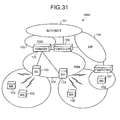
- FIG. 31 is a block diagram illustrating the schematic internal configuration of a radio communication system using the femto BS.
- the same components as those of the radio communication system 100 illustrated in FIG. 30 are denoted by the same reference numerals and the overlapped description of the configuration and the operation will be omitted.
- a radio communication system 100A illustrated in FIG. 31 includes a femto BS 107 that is disposed at home or an office and radio-accommodates the MS 102.
- the femto BS 107 is connected to an ISP 108 through an asymmetric digital subscriber line (hereinafter, simply referred to as ADSL line) or an optical fiber line, and is connected directly from the ISP 108 to the ASN 104 or is connected to the ASN 104 through the Internet 101, for communication.
- ADSL line asymmetric digital subscriber line
- optical fiber line an optical fiber line
- the ASN 104 disposes a femto GW 109 that functions as a communication interface with the femto BS 107 through the ISP 108 or the Internet 101.
- the femto GW 109 realizes encryption communication to prevent wiretapping and falsification of data with the femto BS 107, using IP security (hereinafter, simply referred to as IPsec), and secures security of the ASN 104.
- IPsec IP security
- the MS 102 that is radio-accommodated in the femto BS 107 is limited to the MS 102 of a specific user, such as a household member at home where the femto BS 107 is disposed or a visitor.
- radio communication system 100A regardless of a user using the MS 102 being absent from a place, that is, the MS 102 not existing in a calling area of the femto BS 107, radio communication of the femto BS 107 with respect to the MS 102 is continued. For this reason, a radio transmission output may lead to a factor of waste of useless transmission power or unnecessary radio wave interference for adjacent cells.
- the present invention has been made in view of the above circumstances and it is an object of the present invention to avoid waste of useless transmission power or unnecessary interference for adjacent cells.
- a device disclosed includes a network connection providing unit that provides network connection to a mobile subscriber radio-accommodated in a specific base station among base stations each radio-accommodating mobile subscribers in a corresponding calling area; a receiving unit that receives a message related to movement or position registration of the mobile subscriber; a first subscriber existence determining unit that determines whether the mobile subscriber radio-accommodated in the base station in a specific calling area including a calling area of the specific base station withdraws, when the message is received in the receiving unit; and a command control unit that transmits a transmission stop command that instructs to stop radio transmission to the mobile subscriber, to the specific base station, when it is determined by the first subscriber existence determining unit that the mobile subscriber radio-accommodated in the base station in the specific calling area withdraws.
- a device disclosed includes a network connection providing unit that provides network connection to a mobile subscriber radio-accommodated in a specific base station among base stations each radio-accommodating mobile subscribers in a corresponding calling area; a receiving unit that receives a message related to movement or position registration of the mobile subscriber; a second subscriber existence determining unit that determines whether the mobile subscriber radio-accommodated in the base station in the specific calling area exists, when the message is received in the receiving unit; and a command control unit that transmits a transmission restart command that instructs to restart radio transmission to the mobile subscriber, to the specific base station, when it is determined by the second subscriber existence determining unit that the mobile subscriber radio-accommodated in the base station in the specific calling area exists.
- a method disclosed includes a network connection providing step of providing network connection to a mobile subscriber radio-accommodated in a specific base station among base stations each radio-accommodating mobile subscribers in a corresponding calling area; a receiving step of receiving a message related to movement or position registration of the mobile subscriber; a first subscriber existence determining step of determining whether the mobile subscriber radio-accommodated in the base station in a specific calling area including a calling area of the specific base station withdraws, when the message is received at the receiving step; and a command control step of transmitting a transmission stop command that instructs to stop radio transmission to the mobile subscriber, to the specific base station, when it is determined at the first subscriber existence determining step that the mobile subscriber radio-accommodated in the base station in the specific calling area withdraws.
- a method disclosed includes a network connection providing step of providing network connection to a mobile subscriber radio-accommodated in a specific base station among base stations each radio-accommodating mobile subscribers in a corresponding calling area; a receiving step of receiving a message related to movement or position registration of the mobile subscriber; a second subscriber existence determining step of determining whether the mobile subscriber radio-accommodated in the base station in the specific calling area exists, when the message is received at the receiving step; and a command control step of transmitting a transmission restart command that instructs to restart radio transmission to the mobile subscriber, to the specific base station, when it is determined by the second subscriber existence determining step that the mobile subscriber radio-accommodated in the base station in the specific calling area exists.
- a system disclosed includes base stations each radio-accommodating mobile subscribers in a corresponding calling area; and a gateway device that provides network connection to the mobile subscriber radio-accommodated in a specific base station among the base stations, wherein the gateway device includes a receiving unit that receives a message related to movement or position registration of the mobile subscriber, a first subscriber existence determining unit that determines whether the mobile subscriber radio-accommodated in the base station in a specific calling area including a calling area of the specific base station withdraws, when the message is received in the receiving unit, and a command control unit that transmits a transmission stop command that instructs to stop radio transmission to the mobile subscriber, to the specific base station, when it is determined by the first subscriber existence determining unit that the mobile subscriber radio-accommodated in the base station in the specific calling area withdraws, and the specific base station stops radio transmission to the mobile subscriber, when receiving the transmission stop command.
- a system disclosed includes base stations each radio-accommodating mobile subscribers in a corresponding calling area; and a gateway device that provides network connection to a mobile subscriber radio-accommodated in a specific base station among the base stations, wherein the gateway device includes a receiving unit that receives a message related to movement or position registration of the mobile subscriber, a second subscriber existence determining unit that determines whether the mobile subscriber radio-accommodated in the base station in the specific calling area exists, when the message is received in the receiving unit, and a command control unit that transmits a transmission restart command that instructs to restart radio transmission to the mobile subscriber, to the specific base station, when it is determined by the second subscriber existence determining unit that the mobile subscriber radio-accommodated in the base station in the specific calling area exists, and the specific base station restarts radio transmission to the mobile subscriber, when receiving the transmission restart command.
- a radio transmission state of a specific base station is managed and controlled on the basis of whether a mobile subscriber is radio-accommodated in the specific base station, thereby avoiding waste of useless transmission power or unnecessary interference for adjacent cells in the specific base station.
- the embodiments relate to a radio communication system that has a BS that radio-accommodates a MS for each calling area and a femto GW that provides network connection to the MS radio-accommodated in the femto BS in the BS.
- the femto GW If the femto GW receives a message related to movement or position registration of the MS, when it is determined that an MS radio-accommodated in a BS in a specific calling area including a calling area of a femto BS withdraws, the femto GW transmits a transmission stop command, which instructs to stop radio transmission to the MS, to the femto BS.
- the femto BS if the femto BS receives a transmission stop command, the femto BS stops the radio transmission to the MS. Therefore, waste of useless transmission power or unnecessary interference for adjacent cells in the femto BS can be avoided.
- the femto GW If the femto GW receives a message related to movement or position registration of the MS, when there exists an MS that is radio-accommodated in a BS in a specific calling area, the femto GW transmits a transmission restart command, which instructs to restart radio transmission to the MS, to the femto BS.
- the femto BS receives the transmission restart command, the femto BS restarts the radio transmission to the MS. Therefore, the radio transmission in a stop state can be restarted.
- FIG. 1 is a block diagram illustrating the schematic internal configuration of a radio communication system according to a first embodiment.
- a radio communication system 1 illustrated in FIG. 1 has an ASN 4 that accommodates and connects plural BSs 3 to radio-accommodate plural MSs 2, an Internet 5, a CSN 6 that connects the ASN 4 and the Internet 5, a femto BS 7 that is disposed at home or an office and radio-accommodates the plural MSs 2, and an ISP 8 that is connected to the femto BS 7 and is connected to the Internet 5 through an optical fiber line or an ADSL line.
- the MS 2 corresponds to a personal computer including a radio function, a mobile terminal or a mobile phone terminal.
- Each BS 3 includes a calling area for radio accommodation, and radio-accommodates the MS 2 that exists in the calling area.
- each femto BS 7 includes a calling area for radio accommodation, and radio-accommodates the MS 2 that exists in the calling area and can be connected.
- the BS 3 and the femto BS 7 in the radio communication system 1 are managed in a calling group unit of #1 or #2, for example, and the radio communication system 1 manages a calling group ID (hereinafter, simply referred to as PGID) to identify each calling group and a BSID to identify the BS 3 or the femto BS 7 belonging to the calling group.
- PGID calling group ID
- BSID BSID
- the ASN 4 has plural BSs 3, an ASN-GW 11 that functions as a communication interface between the BS 3 and the CSN 6, a femto GW 12 that functions as a communication interface between the femto BS 7 and the ASN 4 through the ISP 8, and an authentication, authorization, and accounting (hereinafter, simply referred to as AAA) server 13.
- AAA authentication, authorization, and accounting
- FIG. 2 is a block diagram illustrating the schematic internal configuration of the femto BS 7.
- the femto BS 7 illustrated in FIG. 2 has an antenna unit 21 that transmits and receives a radio signal, a duplexer 22 that enables common use of the antenna unit 21 by a transmitting/receiving system, a radio signal receiving unit 23 that receives and demodulates a radio signal from a counterpart destination and decodes an error correcting code, a radio signal transmitting unit 24 that executes error correcting code processing on data transmitted to the counterpart destination, modulates the data, and transmits a radio signal through the antenna unit 21, and a radio transmission/reception control unit 25 that controls the radio signal receiving unit 23 and the radio signal transmitting unit 24.
- the femto BS 7 has a communication interface 26 that functions as an interface with the ISP 8, a femto BS-side encryption/decryption processing unit 27 that encrypts or decrypts an IP packet, a femto BS-side storage unit 28 that stores a variety of information, and a femto BS-side control unit 29 that wholly controls the femto BS 7.
- the communication interface 26 can be directly connected to the femto GW 12 without passing through the ISP 8.
- the femto BS-side storage unit 28 has a state managing unit 31 that manages a self state (active state/idle state) and an access list 33 that manages the MS 2 that can be connected to the femto BS-side storage unit.
- the idle state of the femto BS 7 corresponds to a stop state where radio transmission such as control information with respect to the radio-accommodated MS 2 is stopped and the active state corresponds to an operation state where the stop of radio transmission such as control information with respect to the radio-accommodated MS 2 is released.
- the femto BS-side control unit 29 is relayed or terminated through a radio link protocol and a network-side protocol and enables data communication or authentication of the MS 2.
- FIG. 3 is a block diagram illustrating the schematic internal configuration of the femto GW 12.
- the femto GW 12 illustrated in FIG. 3 has a first communication interface 41 that functions as an interface with the femto BS 7, for example, through the ISP 8 or the Internet 5 and a second communication interface 42 that functions as an interface with the internal device of the ASN 4, such as the ASN-GW 11 or the BS 3.
- the femto GW 12 has a femto GW-side encryption/decryption processing unit 43 that encrypts or decrypts an IP packet exchanged with the femto BS 7 through the first communication interface 41, a femto GW-side storage unit 44 that stores a variety of information, and a femto GW-side control unit 45 that wholly controls the femto GW 12.
- the femto GW-side control unit 45 has an authenticating unit 51 that communicates with the AAA server 13 to execute authentication of the BS 3, the femto BS 7 or the MS 2 and sets a data transmitting path between the femto BS 7 and the femto GW-side control unit 45, and a calling controller (hereinafter, simply referred to as PC) 52 that controls calling with respect to each MS 2.
- PC calling controller
- the authenticating unit 51 is connected to the AAA server 13 for communication, according to necessity, and executes authentication of the femto BS 7.
- the femto BS 7 previously acquires an electronic certificate with respect to the AAA server 13, and the authenticating unit 51 uses the electronic certificate through the AAA server 13 to authenticate the femto BS 7, and obtains the authentication result.
- the authenticating unit 51 When the MS 2 is newly connected to the femto BS 7, the authenticating unit 51 is connected to the AAA server 13 for communication, and obtains a connection authentication result that confirms whether connection of the MS 2 and the femto BS 7 is permitted on the basis of the identification information of the MS 2 and the BSID included in an EAP message from the femto BS 7, through the AAA server 13.
- the AAA server 13 Since the AAA server 13 manages a list of the MSs 2 where connection with the femto BS 7 is permitted, on the basis of information at the time of new arrangement contract of the femto BS 7, the AAA server 13 confirms whether connection of the MS 2 and the femto BS 7 is permitted on the basis of the management contents and the identification information of the MS 2 and the BSID included in the EAP message from the femto BS 7.
- the femto BS 7 can acquire the list of the MSs 2 where connection with the femto BS 7 is permitted as setting information from the AAA server 13, at the time of new connection of the femto BS 7.
- the femto GW-side storage unit 44 has a surrounding BS list management table 61 that manages the BS 3 adjacent for each femto BS 7, for example, the BS 3 belonging to the same PGID as a surrounding BS, a position registration database 62 that manages position information of the MS 2 managed by the femto GW 12, and a femto BS management table 63 that manages state information (active state/idle state) of the femto BS 7 to be self managed.
- a surrounding BS list management table 61 that manages the BS 3 adjacent for each femto BS 7, for example, the BS 3 belonging to the same PGID as a surrounding BS
- a position registration database 62 that manages position information of the MS 2 managed by the femto GW 12
- a femto BS management table 63 that manages state information (active state/idle state) of the femto BS 7 to be self
- the femto GW-side control unit 45 executes a femto BS transmission control determining process to be described below, on the basis of the contents of the surrounding BS list management table 61, the position registration database 62, and the femto BS management table 63.
- the femto GW-side control unit 45 has a pre-movement determining unit 53 that determines whether a first condition where the position registration updated MS 2 exists within the coverage of the femto BS 7 or the BS 3 in the vicinity of the femto BS 7 before moving to the coverage of the movement destination BS is satisfied, on the basis of the surrounding BS list management table 61 and the position registration database 62, when a message of movement or position registration from the MS 2, for example, position registration confirmation is received.
- the femto GW-side control unit 45 has a first connection existence/non-existence determining unit 54 that determines whether a second condition where all of the MSs 2 that can be connected to the femto BS 7 withdraw from the femto BS 7 and the BS 3 belonging to the same PGID as the femto BS 7 is satisfied, when it is determined by the pre-movement determining unit 53 that the first condition is satisfied.
- the femto GW-side control unit 45 has an active state determining unit 55 that determines whether a third condition where a state of the femto BS 7 is an active state is satisfied, when it is determined by the first connection existence/non-existence determining unit 54 that the second condition is satisfied.
- the femto GW-side control unit 45 has a command control unit 56 that determines that the first, second, and third conditions are satisfied, when it is determined by the active state determining unit 55 that the third condition is satisfied, and transmits a transmission stop command (Dormant Command) to the femto BS 7 to stop the radio transmission of the femto BS 7 to the MS 2.
- a transmission stop command Dormant Command
- the femto GW-side control unit 45 also has a second connection existence/non-existence determining unit 57 that determines that a fourth condition where the position registration updated MS 2 does not exist within the coverage of the femto BS 7 or the BS 3 in the vicinity of the femto BS 7 before moving to the coverage of the movement destination BS 3 is satisfied, when it is determined by the pre-movement determining unit 53 that the first condition is not satisfied, and determines whether a fifth condition where the MS 2 that can be connected to the femto BS 7 exists in the femto BS 7 or the BS 3 belonging to the same PGID as the femto BS 7 is satisfied.
- the femto GW-side control unit 45 has an idle state determining unit 58 that determines whether a sixth condition where a state of the femto BS 7 is an idle state is satisfied, when it is determined by the second connection existence/non-existence determining unit 57 that the fifth condition is satisfied.
- the command control unit 56 determines that the fourth, fifth, and sixth conditions are satisfied, when it is determined by the idle state determining unit 58 that the sixth condition is satisfied, and transmits a transmission restart command (Wake-up Command) to the femto BS 7 to restart the stopped radio transmission of the femto BS 7 to the MS 2.
- a transmission restart command (Wake-up Command)
- FIG. 4 is a diagram illustrating contents of the surrounding BS list management table 61 in the femto GW 12.
- the femto GW 12 manages the BS 3 adjacent for each femto BS 7, for example, the BS 3 belonging to the same PGID as the surrounding BS in the surrounding BS list management table 61.
- the setting information of the surrounding BS list management table 61 is obtained by generating a list of the BSs 3 adjacent to an arrangement place applied at the time of new arrangement contract of the femto BS 7 from cell design information.
- the setting information of the surrounding BS list management table 61 can be dynamically set according to movement of the MS 2. That is, when handover of the MS 2 is performed from the femto BS 7 to the movement destination BS 3 or when the MS 2 moves from the femto BS 7 to the movement destination BS 3 and the position thereof is registered, the movement destination BS 3 may be added as the surrounding BS of the femto BS 7 to the surrounding BS list management table 61.
- the femto BS 7 may receive the radio signal of the peripheral BS 3, and add the peripheral BS 3 of the femto BS 7 as the surrounding BS to the surrounding BS list management table 61, on the basis of the radio signal.
- FIG. 5 is a diagram simply illustrating the data configuration of information that is managed by an internal position registration database 62 of the femto GW 12.
- the position registration database 62 manages position information of the MS 2 that is managed by the femto GW 12.
- the position information has a MAC address 62A to identify the MS 2, a PGID 62B to identify a calling group which the MS 2 belongs to, a BSID 62C to identify the BS 3 or the femto BS 7 radio-accommodating the MS 2, a calling period 62D to transmit a calling notification message indicating whether a signal is transmitted to the MS 2 during the idle mode, and a calling offset 62E to manage an offset of timing of the calling period 62D.
- FIG. 6 is a sequence illustrating an internal processing operation of the radio communication system 1 related to initial setting of the femto BS.
- the initial setting of the femto BS corresponds to a setting operation until communication with the MS 2 that can be connected to the femto BS 7 starts through the femto BS 7, from new arrangement of the femto BS 7 in the radio communication system 1.
- the femto BS 7 is newly disposed in a home and is connected to the ISP 8 through an ADSL line or an optical fiber line.
- the femto BS 7 illustrated in FIG. 6 sets an IPsec tunnel to secure communication confidentiality with the femto GW 12 (step S11).
- the femto GW 12 is connected to the AAA server 13 for communication, according to necessity, and executes authentication of the femto BS 7 (step S12). Since the femto BS 7 previously acquires the electronic certificate with respect to the AAA server 13, the AAA server 13 authenticates the femto BS 7 using the electronic certificate.
- the AAA server 13 transmits setting information (Configuration Information) of the femto BS 7 to the femto BS 7 (step S13). If the authentication is succeeded, the femto BS 7 can acquire setting information of the femto BS 7 from servers other than the AAA server 13.
- the femto BS 7 starts a basic operation as a base station (step S14).
- the basic operation as the base station is to radio-transmit control information, such as a preamble, a downlink (hereinafter, simply referred to as DL)/uplink (hereinafter, simply referred to as UL) MAP information (hereinafter, simply referred to as DL/UL-MAP), a down-channel descriptor (hereinafter, simply referred to as DCD)/up-channel descriptor (hereinafter, simply referred to as UCD), to the radio-accommodated MS 2.
- DL downlink
- UL uplink
- DCD down-channel descriptor
- UCD up-channel descriptor
- the femto BS 7 executes an authentication operation of the MS 2 to determine whether connection of the MS 2 is permitted.
- the MS 2 and the femto BS 7 adjust transmission parameters (frequency, timing, and transmission power) through a ranging process (step S15), and negotiate SBC (SS Basic Capability) (step S16).
- SBC SS Basic Capability
- the MS 2 uses a privacy key management (hereinafter, simply referred to as PKM) protocol, and transmits an extensible authentication protocol (hereinafter, simply referred to as EAP) message to authenticate the MS 2 to the femto BS 7 (step S17).
- PKM privacy key management
- EAP extensible authentication protocol
- the PKM is used to transmit the EAP message between the femto BS 7 and the MS 2.
- the EAP message includes identification information of the MS 2 to authenticate the MS 2.
- the femto BS 7 uses an EAP-transfer protocol to transmit the EAP message including its own BSID as well as the identification information of the MS 2 to the femto GW 12 (step S18).
- the authenticating unit 51 in the femto GW 12 uses a RADIUS protocol to transmit the EAP message received from the femto BS 7 to the AAA server 13.
- the AAA server 13 executes connection authentication to confirm whether connection of the MS 2 and the femto BS 7 is permitted, on the basis of management contents related to the connection permission of the femto BS 7 and the MS 2 and the identification information of the MS 2 and the BSID of the femto BS 7 included in the EAP message, and transmits the connection authentication result to the femto GW 12 (step S19).
- the femto GW 12 uses the EAP-transfer protocol to transmit the EAP message of the authentication success to the femto BS 7 (step S20).
- the femto BS 7 adds a MAC (Media Access Control) address to identify the MS 2 of the authentication success to the access list 33 (step S21).
- MAC Media Access Control
- the femto BS 7 transmits the EAP message of the authentication success of the MS 2 to the MS 2 (step S22).
- the femto BS 7 executes a registration (REG) operation (step S23) and starts communication with the MS 2 (step S24).
- REG registration
- the femto GW 12 transmits the authentication failure to the MS 2 through the femto BS 7 and urges the MS 2 to perform reconnection with another femto BS 7 or another BS 3.
- the femto BS 7 transmits the authentication failure to the MS 2 and urges the MS 2 to perform reconnection with another femto BS 7 or another BS 3.
- the case where the MS 2 is newly connected to the newly disposed femto BS 7 is exemplified.
- the MS 2 is connected to the movement destination femto BS 7 according to handover or when the MS 2 during the idle mode returns to the active mode and is connected to the femto BS 7, if the MAC address of the MS 2 does not exist in the access list 33 in the femto BS 7, the connection authentication between the MS 2 and the femto BS 7 in steps S17 to S20 is executed.
- the authentication is succeeded, the MAC address of the MS 2 is added to the access list 33 in the femto BS 7.
- FIG. 7 is a sequence illustrating an internal processing operation of the radio communication system 1 according to movement between calling groups from the femto BS 7 to another BS 3 by the MS 2 during the idle mode.
- the MS 2 illustrated in FIG. 7 transmits a withdrawal request (DREG-REQ) message to the femto BS 7, when the MS 2 transits from the active mode to the idle mode (step S31).
- DREG-REQ withdrawal request
- the femto BS 7 transmits an idle transition request (IM Entry State Change-Request) to the femto GW 12 as a preparation step of when the MS 2 transits to the idle mode (step S32).
- the idle transition request includes information (various registration information, security information, and service flow information) of the MS 2, a PGID of the MS 2, and a BSID to specify a transmission source BS, that is, the femto BS 7.
- the femto GW 12 Since the femto GW 12 manages the PGID, the PCID to identify the PC unit 52 of the femto GW 12, and the calling period as information needed for the MS 2, if the idle transition request is received, the femto GW 12 transmits an idle transition request response (IM Entry State Change-Response) including the PGID, the PCID, and the calling period to the femto BS 7 (step S33).
- IM Entry State Change-Response IM Entry State Change-Response
- the femto BS 7 transmits the withdrawal command (DERG-CMD) message including the calling period to the MS 2 (step S34). If the withdrawal command message is received, the MS 2 transits to the idle mode (step S35).
- the femto BS 7 transmits a calling notification (Paging Advertisement: PAG-ADV) message indicating whether a signal is transmitted to the MS 2, on the basis of the calling period included in the idle transition request response (step S36).
- PAG-ADV a calling notification
- the MS 2 When the MS 2 during the idle mode moves to the BS 3 away from the coverage of the femto BS 7, for example, the BS 3 of #2 (step S37), the MS 2 exists in a calling area of the BS 3 of #2. For this reason, the MS 2 receives the calling notification message from the BS 3 of #2.
- the MS 2 recognizes that the MS 2 moves from the femto BS 7 to the calling area of the BS 3 of #2 and starts the position registration update operation thereof.
- the MS 2 transmits a ranging request (RNG-REQ) message including a PCID and a position registration update flag (hereinafter, simply referred to as LU flag) to the BS 3 of #2 (step S38).
- the LU flag indicates that the ranging request message is a message requesting to register the position.
- the BS 3 of #2 transmits a position registration request (LU Req) including a PGID and a BSID to identify the BS 3 of #2 to the PC unit 52 in the femto GW 12 through the ASN-GW 11 (step S39), on the basis of the PCID from the MS 2, that is, the PCID of the PC unit 52 of the femto GW 12 (step S40).
- LU Req position registration request
- the PC unit 52 in the femto GW 12 transmits a position registration request response (LU Rsp) to the BS 3 of #2 (step S42), through the ASN-GW 11 (step S41).
- LU Rsp position registration request response
- the position registration request response includes key information that is needed to calculate a cipher-based message authentication code (hereinafter, simply referred to as CMAC) to check the validity of the ranging request message received from the MS 2 in step S38 at the side of the BS 3 of #2.
- CMAC cipher-based message authentication code
- the BS 3 of #2 calculates the CMAC of the ranging request message, on the basis of the key information of the CMAC included in the position registration request response, compares the CMAC of the calculation result and the CMAC attached to the ranging request message, and confirms the validity of the ranging request message.
- the BS 3 of #2 transmits the ranging request response (RNG-RSP) message including the confirmation of the validity to the MS 2 (step S43).
- the BS 3 of #2 further transmits the position registration confirmation (LU Confirm) with respect to the position registration request response of step S42 to the PC unit 52 in the femto GW 12 (step S45), through the ASN-GW 11 (step S44).
- the PC unit 52 in the femto GW 12 updates and registers the position information of the MS 2 in the position registration database 62, on the basis of the PGID or the BSID of the BS 3 of #2 included in the position registration request received in step S40 (step S46).
- the femto GW 12 executes a femto BS transmission control determining process (step S47).
- the pre-movement determining unit 53 determines whether a first condition where the position registration updated MS 2 exists within the coverage of the femto BS 7 or the BS 3 in the vicinity of the femto BS 7 before moving to the coverage of the BS 3 of #2 is satisfied, the first connection existence/non-existence determining unit 54 determines whether a second condition where all of the MSs 2 that can be connected to the femto BS 7 withdraw from the femto BS 7 and the BS 3 belonging to the same PGID as the femto BS 7 is satisfied, and the active state determining unit 55 determines whether a third condition where a state of the femto BS 7 is an active state is satisfied.
- the command control unit 56 in the femto GW 12 transmits the transmission stop command to the femto BS 7 to instruct the idle state, that is, the radio transmission stop of the control information with respect to the femto BS 7 (step S48).
- the femto BS 7 transits to the idle state where the radio transmission of the control information is stopped (step S49). As a result, the femto BS 7 can avoid waste of useless transmission power or unnecessary radio wave interference for adjacent cells.
- the femto BS 7 transmits a confirmation response (Ack) indicating the transition of the femto BS 7 to the idle state to the femto GW 12 (step S50).
- Ack confirmation response
- the femto GW 12 updates state information of the femto BS 7 as an idle state in the femto BS management table 63.
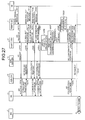
- FIG. 8 is a sequence illustrating an internal processing operation of the radio communication system 1 according to movement between calling groups from another BS 3 to the BS 3 in the vicinity of the femto BS 7 by the MS 2 during an idle mode.
- the MS 2 When the MS 2 during the idle mode moves from the BS 3 of #2 to the BS 3 of #1, the PGID included in the calling notification message received from the BS 3 of #1 and the PGID included in the calling notification message received from the BS 3 of #2 are different from each other. For this reason, the MS 2 recognizes that the MS 2 moves from the femto BS 7 to the calling area of the BS 3 of #1 and starts the position registration update operation thereof.
- the MS 2 during the idle mode transmits a ranging request message including a PCID and a LU flag to the BS 3 of #1 (step S61).
- the BS 3 of #1 transmits a position registration request including the PGID and the BSID to identify the BS 3 of #1 to the PC unit 52 in the femto GW 12, on the basis of the PCID included in the ranging request message (step S63), through the ASN-GW 11 (step S62).
- the PC unit 52 in the femto GW 12 transmits a position registration request response including key information of the CMAC to authenticate the validity of the ranging request message to the BS 3 of #1 (step S65), through the ASN-GW 11 (step S64).
- the BS 3 of #1 calculates the CMAC of the ranging request message, on the basis of the key information of the CMAC included in the position registration request response, compares the CMAC of the calculation result and the CMAC attached to the ranging request message, and confirms the validity of the ranging request message.
- the BS 3 of #1 transmits the ranging request response message including the confirmation of the validity to the MS 2 (step S66).
- the BS 3 of #1 also transmits the position registration confirmation with respect to the position registration request to the PC unit 52 in the femto GW 12 (step S68), through the ASN-GW 11 (step S67).
- the PC unit 52 in the femto GW 12 updates and registers the position information of the MS 2 in the position registration database 62, on the basis of the PGID or the BSID of the BS 3 of #1 included in the position registration request received in step S63 (step S69).
- the femto GW 12 then executes a femto BS transmission control determining process (step S70).
- the pre-movement determining unit 53 determines whether a first condition where the position registration updated MS 2 exists within the coverage of the femto BS 7 or the BS 3 in the vicinity of the femto BS 7 before moving to the BS 3 of #1 is not satisfied, that is the fourth condition is satisfied, the second connection existence/non-existence determining unit 57 determines whether a fifth condition where the current MS 2 is within the coverage of the femto BS 7 or the BS 3 belonging to the same PGID as the femto BS 7 is satisfied, and the idle state determining unit 58 determines whether a sixth condition where a state of the femto BS 7 is an idle state is satisfied.
- the command control unit 56 in the femto GW 12 transmits the transmission restart command to the femto BS 7 to instruct the active state, that is, the radio transmission restart of the control information with respect to the femto BS 7 (step S71).
- the femto BS 7 transits to the idle state where the radio transmission of the control information restarts (step S72). As a result, the femto BS 7 can restart the basis operation as the base station with respect to the MS 2.
- the femto BS 7 transits to the active state where the radio transmission restarts, the femto BS 7 transmits a confirmation response indicating the active state to the femto GW 12 (step S73).
- the femto GW 12 updates state information of the femto BS 7 as the active state in the femto BS management table 63.
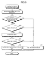
- FIG. 9 is a flowchart illustrating an internal processing operation of the BS 3 (femto BS 7) related to a ranging request receiving process.
- the BS 3 determines whether the MAC address of the MS 2 of the ranging request message exists in the access list 33 (step S82).
- the BS 3 determines whether the CMAC is attached to the ranging request message (step S83).
- the ranging request message to which the CMAC is attached is a ranging request message from the MS 2 moved from the adjacent BS 3 by the handover or the MS 2 whose state returns from the idle mode to the active mode.
- the ranging request message to which the CMAC is not attached is a message that is transmitted from the MS 2 by such as a start process of an initial step after power is supplied.
- the BS 3 acquires the key information to confirm the validity of the CMAC from the femto GW 12, calculates the CMAC on the basis of the acquired key information, and compares the CMAC of the calculation result and the CMAC attached to the ranging request message (step S84).
- the BS 3 determines whether the CMAC of the calculation result and the CMAC attached to the ranging request message are matched with each other, on the basis of the comparison result (step S85).
- the BS 3 determines that the ranging request message has the validity, permits connection with the MS 2 that the ranging request message transmits (step S86), and ends the processing operation illustrated in FIG. 9 .
- step S82: NO When it is determined that the MAC address of the MS 2 does not exist in the access list 33 (step S82: NO), when it is determined that the CMAC is not attached to the ranging request message (step S83: NO) or when it is determined that the CMAC of the calculation result and the CMAC attached to the ranging request message are not matched with each other (step S85: NO), the BS 3 (femto BS 7) determines that the ranging request message received in step S81 does not have the validity, executes full authentication on the femto GW 12 and the AAA server 13 to start authentication of the MS 2 of the ranging request message (step S87), and ends the processing operation illustrated in FIG. 9 .
- the full authentication corresponds to EAP authentication in which the MS 2 uses the PKM protocol to transmit the EAP message including the electronic certificate to the AAA server 13 through the femto BS 7 and the femto GW 12, and the AAA server 13 authenticates the MS 2.
- the femto BS and the femto GW 12 exchange the EAP message with each other, using an EAP transfer protocol, and the femto BS 7 and the AAA server 13 exchange the EAP message with each other, using the authentication protocol, such as the RADIUS.
- the BS 3 uses the EAP transfer protocol to acquire the authentication result of the MS 2 of the AAA server 13 side from the femto GW 12.
- the BS 3 (femto BS 7) permits connection with the MS 2 that sends the ranging request message. Therefore, unjust connection of the MS 2 with respect to the BS 3 (femto BS 7) can be prevented.
- the BS 3 executes the full authentication on the MS 2 that sends the ranging request message. Therefore, unjust connection of the MS 2 with respect to the BS 3 (femto BS 7) can be prevented.
- FIG. 10 is a flowchart illustrating an internal processing operation of the femto BS 7 related to an access list adding process.
- the femto BS 7 illustrated in FIG. 10 determines whether the authentication of the MS 2 is succeeded, on the basis of the EAP message (step S92).
- step S92 When the authentication of the MS 2 is succeeded (step S92: YES), the femto BS 7 adds the MAC address of the MS 2 to the access list 33 (step S93) and ends the processing operation illustrated in FIG. 10 .
- step S92 NO
- the femto BS 7 ends the processing operation illustrated in FIG. 10 .
- the femto BS 7 transmits the EAP message of the authentication success or the authentication failure, which is received using the EAP transfer protocol, to the MS 2.
- the MAC address of the MS 2 that is added to the access list 33 may be automatically erased after a constant time passes or erased according to a command.
- the femto BS 7 can recognize the connectable MS 2 on the basis of the contents of the access list 33.
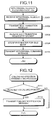
- FIG. 11 is a flowchart illustrating an internal processing operation of the femto BS 7 related to a withdrawal request receiving process.
- the femto BS 7 illustrated in FIG. 11 transmits the idle transition request of the MS 2 to the PC unit 52 in the femto GW 12 (step S102).
- the femto GW 12 registers information of the MS 2 and the BSID included in the idle transition request.
- the femto BS 12 stores the PCID to identify the PC unit 52 thereof and an idle mode parameter (calling period) in the idle transition request response, and transmits the idle transition request response to the femto BS 7.
- the femto GW 12 sets a system timer and monitors whether the position registration update of the MS 2 is performed before the system timer times up.
- the femto GW 12 can erase the association information of the MS 2.
- the PC unit 52 in the femto GW 12 updates and registers the idle mode parameter (calling period or the like) as the position information of the MS 2 in the position registration database 62.
- the femto BS 7 stores the idle mode parameter (calling period or the like) that is included in the idle transition request response (step S104), transmits the withdrawal command message including the parameter to the MS 2 (step S105), and ends the processing operation illustrated in FIG. 11 .
- the MS 2 transits to the idle mode according to the withdrawal command message and stores the idle mode parameter (calling period or the like) that is included in the withdrawal command message.
- the MS 2 regularly receives a calling notification message indicating whether a signal is transmitted from the femto BS 7, on the basis of the stored idle mode parameter (calling period or the like).
- the MS 2 can transit to the idle mode.
- the MS 2 can regularly receive the calling notification message indicating whether a signal is transmitted from the femto BS 7, on the basis of the calling period, even during the idle mode, and recognize whether a signal is transmitted.
- FIG. 12 is a flowchart illustrating an internal processing operation of the femto BS 7 related to a calling notification transmitting process.
- the femto BS 7 determines whether the calling period reaches the calling period of the idle mode parameter (step S111).
- step S111 YES
- the femto BS 7 transmits the calling notification message to the MS 2 (step S112) and proceeds to step S111.
- step S111 NO
- the femto BS 7 continuously executes the determining operation of step S111, until the calling period reaches the calling period of the idle mode parameter.
- the MS 2 can recognize whether a signal is transmitted.
- FIG. 13 is a flowchart illustrating an internal processing operation of the femto BS 7 (BS 3) related to a position registering ranging request receiving process.
- the MS 2 starts the position registration update operation to register the current position thereof regularly or when the MS 2 moves to the coverage of the BS 3 belonging to a new calling group.
- the regular position registration update is to transmit the position registering ranging request message to the BS 3 or the femto BS 7, using a point of time when an internal timer of the MS 2 times up as start timing.
- the position registering ranging request message is transmitted to the BS 3 or the femto BS 7, using a point of time when the PGID of the calling notification message to be received changes as start timing.
- the MS 2 transmits the ranging request message (position registering ranging request message) including the PCID and the LU flag to the movement destination femto BS 7 (BS 3).
- the PCID corresponds to a newest PCID in the PCIDs notified at the time of transiting to the idle mode or immediately previous position registration update.
- the femto BS 7 (BS 3) illustrated in FIG. 13 transmits the position registration request including the PCID and the BSID from the MS 2 to the PC unit 52 in the femto GW 12 through the ASN-GW 11, on the basis of the PCID included in the ranging request message (step S122).
- the femto GW 12 updates the position information of the MS 2 in the position registration database 62, on the basis of the BSID closest to the MS 2 and the PGID related to the MS 2 included in the position registration request.
- the femto GW 12 transmits the position registration request response to the femto BS 7 (BS 3), and resets the system timer.
- the timer time of the system timer is set to be slightly longer than the timer time of the internal timer of the MS 2.
- the femto BS 7 calculates the CMAC of the ranging request message, on the basis of the key information of the CMAC included in the position registration request response, compares the CMAC of the calculation result and the CMAC attached to the ranging request message, and confirms the validity of the ranging request message received in step S121 (step S124).
- the femto BS 7 (BS 3) transmits the ranging request response message including the confirmation of the validity to the MS 2, transmits the position registration confirmation with respect to the position registration request to the femto GW 12 through the ASN-GW 11 (step S125), and ends the processing operation illustrated in FIG. 13 .
- the femto BS 7 (BS 3) transmits the ranging request response message including validity confirmation impossibility to the MS 2 in step S125 and ends the processing operation illustrated in FIG. 13 .
- the ranging request response message is transmitted to the MS 2 and the position registration confirmation is transmitted to the femto GW 12. Therefore, the position registration can be notified to the MS 2 and the femto GW 12.
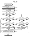
- FIG. 14 is a flowchart illustrating an internal processing operation of the femto GW 12 related to a transmission stop process.
- the femto GW 12 transmits the position registration request response including the key information to check the CMAC of the ranging request message at the side of the movement destination BS 3 (femto BS 7) to the movement destination BS 3 (femto BS 7) (step S132).
- the femto GW 12 updates the position information of the MS 2 in the position registration database 62, on the basis of the BSID and the PGID included in the previously received position registration request (step S134).
- the pre-movement determining unit 53 of the femto GW 12 determines whether a first condition where the position registration updated MS 2 exists within the coverage of the femto BS 7 or the BS 3 in the vicinity of the femto BS 7 before moving to the coverage of the movement destination BS 3 is satisfied, on the basis of the contents of the position registration database 62 (step S135).
- the first connection existence/non-existence determining unit 54 of the femto GW 12 determines whether a second condition where all of the MSs 2 that can be connected to the femto BS 7 withdraw from the femto BS 7 and the BS 3 belonging to the same PGID as the femto BS 7 is satisfied (step S136).
- step S136 When it is determined by the first connection existence/non-existence determining unit 54 that the second condition is satisfied (step S136: YES), the active state determining unit 55 of the femto GW 12 determines whether a third condition where a state of the femto BS 7 is an active state is satisfied (step S137).
- step S137 When it is determined by the active state determining unit 55 that the third condition is satisfied (step S137: YES), the command control unit 56 of the femto GW 12 transmits a transmission stop command to the femto BS 7 to instruct the idle state, that is, the radio transmission stop of the control information, with respect to the femto BS 7 (step S138).
- the femto BS 7 transits to the idle state where the radio transmission of the control information is stopped. As a result, the femto BS 7 can avoid waste of useless transmission power or unnecessary interference for adjacent cells.
- the femto GW 12 transits to a state in which the femto GW 12 waits for receiving the confirmation response indicating the transition to the idle state from the femto BS 7 (step S139).
- step S140 If the confirmation response of the idle state is received (step S140), the femto GW 12 updates state information of the femto BS 7 as an idle state in the femto BS management table 63 (step S141), and ends the processing operation illustrated in FIG. 14 .
- step S135 When it is determined by the pre-movement determining unit 53 that the first condition is not satisfied (step S135: NO), it is determined by the first connection existence/non-existence determining unit 54 that the second condition is not satisfied (step S136: NO), or it is determined by the active state determining unit 55 that the third condition is not satisfied (step S137: NO), the femto GW 12 ends the processing operation illustrated in FIG. 14 .
- the transmission stop process of the femto GW 12 side illustrated in FIG. 14 if the position registration confirmation of the MS 2 is received, when the contents of the position registration database 62 are updated and the first, second, and third conditions are satisfied on the basis of the contents of the position registration database 62, the transmission stop command is transmitted to the femto BS 7. Therefore, the femto BS 7 side can avoid waste of useless transmission power or unnecessary interference for adjacent cells.
- FIG. 15 is a flowchart illustrating an internal processing operation of the femto BS 7 related to a transmission stop command receiving process.
- the femto BS 7 illustrated in FIG. 15 determines whether the MS 2 exists within the coverage of the femto BS 7 (step S152).
- the femto BS 7 transits to the idle state where the radio communication is stopped (step S153), and transmits the confirmation response indicating the transition of the femto BS 7 to the idle state to the femto GW 12 (step S154).
- the femto BS 7 ends the processing operation illustrated in FIG. 15 while maintaining a reception waiting state of the transmission restart command.
- the femto BS 7 side During the transmission stop command receiving process of the femto BS 7 side illustrated in FIG. 15 , if the reception stop command is received from the femto GW 12, the femto BS 7 transits to the idle state where the radio transmission of the control information is stopped. As a result, the femto BS 7 side can avoid waste of useless transmission power or unnecessary interference for adjacent cells.
- FIG. 16 is a flowchart illustrating an internal processing operation of the femto GW 12 related to a transmission control process.
- the femto GW 12 illustrated in FIG. 16 updates the position information of the MS 2 in the position registration database 62, on the basis of the BSID and the PGID included in the previously received position registration request (step S162).
- the pre-movement determining unit 53 of the femto GW 12 determines whether a first condition where the position registration updated MS 2 exists within the coverage of the femto BS 7 or the BS 3 in the vicinity of the femto BS 7 before moving to the coverage of the movement destination BS 3 is satisfied, on the basis of the contents of the position registration database 62 (step S163).
- the first connection existence/non-existence determining unit 54 of the femto GW 12 determines whether a second condition where all of the MSs 2 that can be connected to the femto BS 7 withdraw from the femto BS 7 and the BS 3 belonging to the same PGID as the femto BS 7 is satisfied (step S164).
- step S164 When it is determined by the first connection existence/non-existence determining unit 54 that the second condition is satisfied (step S164: YES), the active state determining unit 55 of the femto GW 12 determines whether a third condition where a state of the femto BS 7 is an active state is satisfied (step S165).
- step S165 When it is determined by the active state determining unit 55 that the third condition is satisfied (step S165: YES), the command control unit 56 of the femto GW 12 transmits a transmission stop command to the femto BS 7 to instruct the idle state, that is, the radio transmission stop of the control information, with respect to the femto BS 7 (step S166).
- the femto BS 7 transits to the idle state where the radio transmission of the control information is stopped. As a result, the femto BS 7 can avoid waste of useless transmission power or unnecessary interference for adjacent cells.
- the femto GW 12 transits to a state in which the femto GW 12 waits for receiving the confirmation response indicating the state of the femto BS 7 from the femto BS 7 (step S167). If the transmission stop command is received, the femto BS 7 transits from the active state to the idle state. For this reason, the femto BS 7 transmits the confirmation response of the idle state to the femto GW 12.
- step S168 If the confirmation response indicating the state of the femto BS 7 is received (step S168), the femto GW 12 updates state information of the femto BS 7 in the femto BS management table 63 (step S169), and ends the processing operation illustrated in FIG. 16 .
- step S163 NO
- the pre-movement determining unit 53 in the femto GW 12 determines that a fourth condition is satisfied.
- the second connection existence/non-existence determining unit 57 in the femto GW 12 determines whether a fifth condition where the current MS 2 exists in the femto BS 7 or the BS 3 belonging to the same PGID as the femto BS 7 is satisfied (step S170).
- step S170 When it is determined by the second connection existence/non-existence determining unit 57 that the fifth condition is satisfied (step S170: YES), the idle state determining unit 58 in the femto GW 12 determines whether a sixth condition where the femto BS 7 is in an idle state is satisfied (step S171).
- step S171 When it is determined by the idle state determining unit 58 that the sixth condition is satisfied (step S171: YES), the command control unit 56 in the femto GW 12 transmits the transmission restart command to the femto BS 7 to instruct the femto BS 7 to transit to the active state, that is, restart the radio transmission of the control information (step S172).
- the femto BS 7 transits to the active state where the radio transmission of the control information restarts. As a result, the femto BS 7 restarts the basic operation as the base station with respect to the MS 2.
- the femto GW 12 transits to step S167 to transit to a state in which the femto GW 12 waits for receiving the confirmation response indicating the state information from the femto BS 7. If the transmission restart command is received, the femto BS 7 transits from the idle state to the active state. Therefore, the femto BS 7 transits to step S167 to transmit the confirmation response of the active state to the femto GW 12.
- the femto GW 12 updates the state information of the femto BS 7 as the active state in the femto BS management table 63 in step S168, and ends the processing operation illustrated in FIG. 16 .
- step S164: NO When it is determined by the first connection existence/non-existence determining unit 54 that the second condition is not satisfied (step S164: NO), it is determined by the active state determining unit 55 that the third condition is not satisfied (step S165: NO), it is determined by the second connection existence/non-existence determining unit 57 that the fifth condition is not satisfied (step S170: NO), or it is determined by the idle state determining unit 58 that the sixth condition is not satisfied (step S171: NO), the femto GW 12 ends the processing operation illustrated in FIG. 16 .
- the transmission stop command is transmitted to the femto BS 7. Therefore, the femto BS 7 side can avoid waste of useless transmission power or unnecessary interference for adjacent cells.
- the transmission restart command is transmitted to the femto BS 7. Therefore, the femto BS 7 side can restart the radio transmission of the control information.
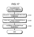
- FIG. 17 is a flowchart illustrating an internal processing operation of the femto BS 7 related to a transmission restart command receiving process.
- the femto BS 7 illustrated in FIG. 17 transits to the active state where the radio transmission of the control information restarts (step S182), and transmits the confirmation response indicating the active state to the femto GW 12 (step S183).
- the femto BS 7 ends the processing operation illustrated in FIG. 17 while maintaining a reception waiting state of the transmission stop command.
- the femto BS 7 During the transmission restart command receiving process of the femto BS 7 side illustrated in FIG. 17 , if the transmission restart command is received from the femto GW 12, the femto BS 7 transits to the active state where the radio transmission of the control information in the stop state restarts. As a result, the femto BS 7 side can restart the radio transmission of the control information.
- the transmission stop command is transmitted to the femto BS 7. Therefore, the femto BS 7 side can avoid waste of useless transmission power or unnecessary interference for adjacent cells.
- the transmission restart command is transmitted to the femto BS 7. Therefore, the femto BS 7 side can restart the radio transmission of the control information.
- the PC unit 52 with respect to the MS 2 can be provided in the femto GW 12, the PC unit 52 in the femto GW 12 can always acquire the newest position information of the MS 2, and the active/idle state of the femto BS 7 can be managed.
- it has less e expansibility of the system to dispose the PC unit 52 in the femto GW 12 at all times.
- a radio communication system 1A according to an embodiment that corresponds to the case where the PC unit 52 is provided in the ASN-GW 11 other than the femto GW 12 will be described below as a second embodiment.
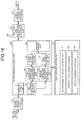
- FIG. 18 is a block diagram illustrating the schematic internal configuration of the femto GW 12 according to a second embodiment.
- FIG. 19 is a block diagram illustrating the schematic internal configuration of an ASN-GW 11A according to the second embodiment.
- the same components as those of the first embodiment are denoted by the same reference numerals and the overlapped description of the configuration and operation is omitted.
- a femto GW-side control unit 45A in a femto GW 12A illustrated in FIG. 18 does not include the PC unit 52 having a calling control function but the authenticating unit 51, the pre-movement determining unit 53, the first connection existence/non-existence determining unit 54, the active state determining unit 55, the command control unit 56, the second connection existence/non-existence determining unit 57, and the idle state determining unit 58.
- the ASN-GW 11A illustrated in FIG. 19 has a third communication interface 71 that functions as a communication interface connected to a BS 3 or an internal device of an ASN 4 such as the femto GW 12, a fourth communication interface 72 that functions as a communication interface with a CSN 6, an ASN-GW-side storage unit 73 that stores a variety of information, and an ASN-GW-side control unit 74 that wholly controls the ASN-GW 11A.
- a PC unit 52A that has a calling controller function is incorporated.
- the AAA server 13 manages the list of the PCID of the ASN-GW 11A and the BSID of the femto BS 7 connected to the MS 2 together with the identification information related to the MS 2 that permits connection with the femto BS 7, on the basis of the information at the time of new arrangement contract of the femto BS 7.
- FIG. 20 is a sequence illustrating an internal processing operation of the radio communication system 1A when the MS 2 starts to be newly connected to the femto BS 7.
- the MS 2 and the femto BS 7 illustrated in FIG. 20 adjust transmission parameters (frequency, timing, and transmission power) through a ranging process (step S191), and negotiate SBC (step S192).
- the MS 2 uses a PKM protocol to transmit an EAP message to authenticate the MS 2 to the femto BS 7 (step S193).
- the EAP message includes identification information of the MS 2 to authenticate the MS 2.
- the femto BS 7 uses an EAP transfer protocol to transmit the EAP message including its own BSID as well as the identification information of the MS 2 to the femto GW 12A (step S194).
- the authenticating unit 51 in the femto GW 12A uses a RADIUS protocol to transmit the EAP message received from the femto BS 7 to the AAA server 13.
- the AAA server 13 executes connection authentication to confirm whether connection of the MS 2 and the femto BS 7 is permitted, on the basis of management contents related to the connection permission of the femto BS 7 and the MS 2 and the identification information of the MS 2 and the BSID of the femto BS 7 included in the EAP message, and transmits the connection authentication result to the femto GW 12A (step S195).
- the femto GW 12A uses the EAP transfer protocol to transmit the EAP message of the authentication success to the femto BS 7 (step S196).
- the femto BS 7 adds a MAC address of the MS 2 of the authentication success to the access list 33 (step S197).
- the femto BS 7 transmits the EAP message of the authentication success of the MS 2 to the MS 2 (step S198).
- the femto BS 7 executes a registration operation (step S199), and starts communication with the MS 2 (step S200).
- the femto GW 12A transmits the authentication failure to the MS 2 through the femto BS 7 and urges the MS 2 to perform reconnection with another femto BS 7 or another BS 3.
- the femto BS 7 transmits the authentication failure to the MS 2 and urges the MS 2 to perform reconnection with another femto BS 7 or another BS 3.
- FIG. 21 is a sequence illustrating an internal processing operation of the radio communication system 1A when idle mode transition is performed, after handover according to movement between calling groups from the femto BS 7 to another BS 3.
- the MS 2 illustrated in FIG. 21 transits to the idle mode after the handover from the femto BS 7 to the movement destination BS 3 (step S211), the MS 2 transmits a withdrawal request message to the movement destination BS 3 (step S212).
- the movement destination BS 3 transmits an idle transition request to the PC unit 52A in the ASN-GW 11A as a preparation step of when the MS 2 transits to the idle mode (step S213).
- the idle transition request includes a BSID to specify a transmission source BS, that is, the movement destination BS, a PCID to identify the PC unit 52 in the ASN-GW 11A, and information (various registration information, security information, service flow information, and the like) of the MS 2.
- the PC unit 52 in the ASN-GW 11A manages the PGID, the PCID to identify the PC unit 52 in the ASN-GW 11A, and the calling period as information needed for the MS 2. For this reason, if the idle transition request is received, the PC unit 52 in the ASN-GW 11A transmits an idle transition request to the AAA server 13 (step S214).
- the AAA server 13 acquires the MS associated information related to the femto GW 12 and the femto BS 7 connected to the MS 2 during the management according to the information of the MS 2 included in the idle transition request, and transmits an idle transition request response including the MS associated information to the ASN-GW 11A (step S215).
- the ASN-GW 11A transmits the idle transition request response to the movement destination BS 3 (step S216).
- the movement destination BS 3 transmits a withdrawal command message including the calling period with respect to the withdrawal request message from the MS 2, to the MS 2 (step S217). As a result, if the withdrawal command message is received, the MS 2 transits to the idle mode (step S218).
- the ASN-GW 11A specifies the femto GW 12A of the femto BS 7 that the MS 2 can be connected, from the information of the MS 2 obtained from the idle transition request response.
- the ASN-GW 11A transmits the position information of the MS 2 to the femto GW 12A (step S219).
- the position information of the MS 2 includes the PGID of the calling group where the MS 2 exists and the BSID of the movement destination BS 3 where the MS 2 is covered.
- the femto GW 12A updates the position information of the MS 2 in the position registration database 62, on the basis of the position information of the MS 2 (step S220) and transmits the confirmation response with respect to the position information of step S219 to the ASN-GW 11A (step S220A).
- the femto GW 12A executes the femto BS transmission control determining process, on the basis of the contents of the position registration database 62 (step S221).
- the command control unit 56 in the femto GW 12A transmits a transmission stop command to the femto BS 7 to instruct the idle state, that is, the radio transmission stop of the control information, with respect to the femto BS 7 (step S222).
- the femto BS 7 transits to the idle state where the radio transmission of the control information is stopped (step S223). As a result, the femto BS 7 can avoid waste of useless transmission power or unnecessary radio wave interference for adjacent cells.
- the femto BS 7 transits to the idle state where the radio transmission is stopped, the femto BS 7 further transmits a confirmation response indicating the idle state to the femto GW 12 (step S224).
- the femto GW 12A updates state information of the femto BS 7 as an idle state in the femto BS management table 63.
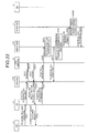
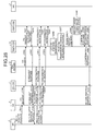
- FIG. 22 is a sequence illustrating an internal processing operation of the radio communication system 1A according to movement between calling groups from another BS 3 to the BS 3 in the vicinity of the femto BS 7.
- the MS 2 moves from the another BS 3 to the BS 3 in the vicinity of the femto BS 7, the MS 2 starts the position registration update operation thereof.
- the MS 2 illustrated in FIG. 22 transmits a ranging request message (position registering ranging request message) including a PCID and a LU flag to the movement destination BS 3 (step S231).
- the movement destination BS 3 transmits a position registration request including a PGID and a BSID to identify the BS 3 to the ASN-GW 11A, on the basis of the PCID included in the ranging request message (step S232).
- the PC unit 52A in the ASN-GW 11A determines whether the movement destination BS 3 side holds MS associated information (security information) related to the MS 2 including key information of the CMAC to authenticate the validity of the ranging request message from the MS 2.
- MS associated information security information
- the PC unit 52A in the ASN-GW 11A transmits a text request (Context-Req) requesting to transmit the key information to the AAA server 13 (step S233).
- the AAA server 13 transmits the key information to authenticate the validity of the ranging request message of the MS 2 and the MS associated information, that is, a text report (Context-Rpt) including information of the femto BS 7 and the femto GW 12A to the PC unit 52A in the ASN-GW 11A (step S234).
- a text report Context-Rpt
- the PC unit 52A in the ASN-GW 11A stores the key information of the CMAC included in the text report in a position registration request response, and transmits the position registration request response to the movement destination BS 3 (step S235).
- the movement destination BS 3 calculates the CMAC of the ranging request message on the basis of the key information of the CMAC included in the position registration request response, compares the CMAC of the calculation result and the CMAC attached to the ranging request message, and confirms the validity of the ranging request message.
- the movement destination BS 3 transmits the ranging request response message including the confirmation of the validity, which responses to the ranging request message, to the MS 2 (step S236).
- the movement destination BS 3 also transmits a position registration confirmation with respect to the position registration request of step S235 to the PC unit 52A in the ASN-GW 11A (step S237).
- the PC unit 52A in the ASN-GW 11A updates and registers the position information of the MS 2, on the basis of the PGID or the BSID of the movement destination BS 3 included in the position registration request previously received in step S232.
- the ASN-GW 11A specifies the femto GW 12A of the femto BS 7 that the MS 2 can be connected, from the information of the MS 2 obtained from the position registration request of step S232.
- the ASN-GW 11A transmits the position information of the MS 2 to the femto GW 12A (step S238).
- the position information of the MS 2 includes the PGID where the MS 2 exists and the BSID of the movement destination BS 3 or the movement destination femto BS 7 where the MS 2 is covered.
- the femto GW 12A updates the contents of the position registration database 62 on the basis of the position information of the MS 2 (step S239), and transmits the confirmation response with respect to the position information to the ASN-GW 11A (step S240).
- the femto GW 12A executes the femto BS transmission control determining process, on the basis of the contents of the position registration database 62 (step S241).
- the femto GW 12A transmits a transmission restart command to the femto BS 7 to instruct the idle state, that is, the radio transmission restart of the control information with respect to the femto BS 7 (step S242).
- the femto BS 7 transits to the active state where the radio transmission of the control information restarts (step S242A). As a result, the femto BS 7 restarts the basic operation as a base station with respect to the MS 2.
- the femto BS 7 transits to the active state where the radio transmission restarts, the femto BS 7 further transmits a confirmation response indicating the active state to the femto GW 12A (step S243).
- the femto GW 12A updates an active state of the femto BS 7 as state information in the femto BS management table 63.
- the PC unit 52A in the ASN-GW 11A transmits the position registration request response including the key information of the CMAC to the movement destination BS 3 in step S235.
- the MS 2 When the MS 2 transits to the idle mode, the MS 2 transmits the withdrawal request message to the BS 3 where the MS 2 currently belongs.
- the BS 3 transmits the idle transition request of the MS 2 to the PC unit 52A in the ASN-GW 11A.
- the idle transition request includes the BSID to specify the transmission source BS and the information (various registration information, security information, service flow information, and the like) of the MS 2.
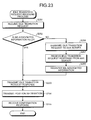
- FIG. 23 is a flowchart illustrating an internal processing operation of the ASN-GW 11A related to an idle transition request receiving process.
- the ASN-GW 11A illustrated in FIG. 23 determines whether the MS associated information related to the MS 2 of the idle transition request is held (step S252).
- the MS associated information includes the key information of the CMAC in addition to the information of the femto BS 7 and the femto GW 12A that can be connected to the MS 2.
- the ASN-GW 11A transmits the idle transition request response including the key information of the CMAC in the MS associated information to the movement destination BS 3 (step S253).
- the ASN-GW 11A specifies the femto GW 12A of the femto BS 7 that the MS 2 can be connected, from the held MS associated information or the MS associated information obtained from the idle transition request response to be described below.
- the ASN-GW 11A transmits the position information of the MS 2 to the femto GW 12A (step S254).
- the position information of the MS 2 includes the PGID and the BSID where the MS 2 exists.
- step S255 If the confirmation response from the femto GW 12A with respect the position information is received (step S255), the ASN-GW 11A ends the processing operation illustrated in FIG. 23 .
- step S252 NO
- the ASN-GW 11A transmits the idle transition request to the AAA server 13 (step S256).
- the AAA server 13 acquires the MS associated information related to the MS 2, on the basis of the information of the MS 2 included in the idle transition request, and transmits the idle transition request response including the acquired MS associated information to the ASN-GW 11A.
- the ASN-GW 11A acquires the MS associated information related to the MS 2 that is included in the idle transition request response, registers the MS associated information related to the MS 2 (step S258), and transits to step S253 to transmit the idle transition request response to the BS 3.
- the idle transition request receiving process of the ASN-GW 11A side illustrated in FIG. 23 if the idle transition request is received from the movement destination BS 3, when it is determined whether the MS associated information related to the MS 2 is held and the MS associated information related to the MS 2 is held, the idle transition request response that includes the key information of the CMAC in the MS associated information is transmitted to the movement destination BS 3. Therefore, the ASN-GW 11A side can provide the key information of the CMAC to confirm the validity of the ranging request message of the MS 2 to the movement destination BS 3.
- the ASN-GW 11A side can provide the key information of the CMAC to confirm the validity of the ranging request message of the MS 2 to the movement destination BS 3.
- FIG. 24 is a flowchart illustrating an internal processing operation of the femto GW 12A related to a transmission stop process according to position information reception.
- step S261 If the position information of the MS 2 is received from the ASN-GW 11A (step S261), the femto GW 12A illustrated in FIG. 24 updates the position information of the MS 2 in the position registration database 62 on the basis of the position information (step S262), and transmits the confirmation response with respect to the position information to the ASN-GW 11A (step S263).
- the pre-movement determining unit 53 in the femto GW 12A determines whether a first condition where the position registration updated MS 2 exists within the coverage of the femto BS 7 or the BS 3 in the vicinity of the femto BS 7 before moving to the coverage of the movement destination BS 3 is satisfied, on the basis of the contents of the position registration database 62 (step S264).
- the first connection existence/non-existence determining unit 54 in the femto GW 12A determines whether a second condition where all of the MSs 2 that can be connected to the femto BS 7 withdraw from the femto BS 7 and the BS 3 belonging to the same PGID as the femto BS 7 is satisfied (step S265).
- step S265 When it is determined by the first connection existence/non-existence determining unit 54 that the second condition is satisfied (step S265: YES), the active state determining unit 55 in the femto GW 12A determines whether a third condition where a state of the femto BS 7 is an active state is satisfied (step S266).
- step S266 When it is determined by the active state determining unit 55 that the third condition is satisfied (step S266: YES), the command control unit 56 in the femto GW 12A transmits the transmission stop command to the femto BS 7 to instruct the idle state, that is, the radio transmission stop of the control information, with respect to the femto BS 7 (step S267).
- the femto GW 12A updates the state information of the femto BS 7 as the idle state in the femto BS management table 63.
- step S264 NO
- step S265 NO
- step S265 NO
- step S266 NO
- the transmission stop process of the femto GW 12 side illustrated in FIG. 24 if the position information of the MS 2 is received through the ASN-GW 11A, when the contents of the position registration database 62 are updated and the first, second, and third condition are satisfied on the basis of the contents of the position registration database 62, the transmission stop command is transmitted to the femto BS 7. Therefore, the femto BS 7 side can avoid waste of useless transmission power or unnecessary interference for adjacent cells.
- the MS 2 When the MS 2 moves to the BS 3 in the vicinity of the femto BS 7, the MS 2 transmits the ranging request message including the PCID and the LU flag to the movement destination BS 3. If the ranging request message is received from the MS 2, the movement destination BS 3 transmits the position registration request including the PGID and the BSID to identify the BS 3 to the ASN-GW 11A.
- FIG. 25 is a flowchart illustrating an internal processing operation of the ASN-GW 11A related to a position registration request receiving process.
- step S271 If the position registration request of the MS 2 is received from the movement destination BS 3 (step S271), the ASN-GW 11A illustrated in FIG. 25 determines whether the MS associated information related to the MS 2 is held (step S272).
- step S272 When the MS associated information related to the MS 2 is held (step S272: YES), the ASN-GW 11A transmits the position registration request response with respect to the position registration request to the movement destination BS 3 (step S273).
- step S274 If the position registration confirmation with respect to the position registration request response is received from the movement destination BS 3 (step S274), the ASN-GW 11A executes the position registration update of the MS 2, on the basis of the PGID or the BSID of the movement destination BS 3 included in the position registration request previously received in step S271 (step S275), and ends the processing operation illustrated in FIG. 25 .
- the ASN-GW 11A specifies the femto GW 12A of the femto BS 7 that the MS 2 can be connected, from the information of the MS 2 obtained from the position registration request, and transmits the position information of the MS 2 to the femto GW 12 (step S276).
- step S277 If the confirmation response with respect to the position information from the femto GW 12 is received (step S277), the ASN-GW 11A ends the processing operation illustrated in FIG. 25 .
- the ASN-GW 11A transmits the text request requesting to transmit the key information of the CMAC to confirm the validity of the ranging request message from the MS 2 to the AAA server 13 (step S278).
- the ASN-GW 11A registers the MS associated information that is included in the text report (step S280), and transits to step S273 to transmit the position registration request response including the key information of the CMAC to confirm the validity of the ranging request message to the movement destination BS.
- the ASN-GW 11A side can provide the key information of the CMAC to confirm the validity of the ranging request message of the MS 2 to the movement destination BS 3.
- the ASN-GW 11A side can provide the key information of the CMAC to confirm the validity of the ranging request message of the MS 2 to the movement destination BS 3.
- FIG. 26 is a flowchart illustrating an internal processing operation of the femto GW 12A related to a transmission control process according to position information reception.
- step S291 If the position information is received from the ASN-GW 11A (step S291), the femto GW 12A illustrated in FIG. 26 updates the position information of the MS 2 in the position registration database 62 on the basis of the position information (step S292).
- the femto GW 12A transmits the confirmation response with respect the position information from the ASN-GW 11A to the ASN-GW 11A (step S293).
- the pre-movement determining unit 53 in the femto GW 12A determines whether a first condition where the position registration updated MS 2 exists within the coverage of the femto BS 7 or the BS 3 in the vicinity of the femto BS 7 before moving to the movement destination BS is satisfied, on the basis of the contents of the position registration database 62 (step S294).
- the first connection existence/non-existence determining unit 54 in the femto GW 12A determines whether a second condition where all of the MSs 2 that can be connected to the femto BS 7 withdraw from the femto BS 7 and the BS 3 belonging to the same PGID as the femto BS 7 is satisfied (step S295).
- the active state determining unit 55 in the femto GW 12A determines whether a third condition where a state of the femto BS 7 is an active state is satisfied (step S296).
- step S296 When it is determined by the active state determining unit 55 that the third condition is satisfied (step S296: YES), the command control unit 56 in the femto GW 12A transmits the transmission stop command to the femto BS 7 to instruct the idle state, that is, the radio transmission stop of the control information, with respect to the femto BS 7 (step S297).
- the femto BS 7 transits to the idle state where the radio transmission of the control information is stopped. As a result, the femto BS 7 stops the basic operation as the base station with respect to the MS 2.
- step S298 If the confirmation response with respect to the command from the femto BS 7 is received (step S298), for example, the confirmation response indicating the idle state with respect to the transmission stop command is received, the femto GW 12A updates the state information of the femto BS 7 as the idle state in the femto BS management table 63.
- the second connection existence/non-existence determining unit 57 in the femto GW 12A determines that a fourth condition where the position registration updated MS 2 does not exist within the coverage of the femto BS 7 or the BS 3 in the vicinity of the femto BS 7 before moving to the coverage of the movement destination BS 3 is satisfied, and determines whether a fifth condition where the current MS 2 exists in the femto BS 7 or the BS 3 belonging to the same PGID as the femto BS 7 is satisfied (step S299).
- the idle state determining unit 58 in the femto GW 12A determines that a sixth condition where the femto BS 7 is in the idle state is satisfied (step S300).
- step S300 When it is determined by the idle state determining unit 58 that the sixth condition is satisfied (step S300: YES), the command control unit 56 in the femto GW 12A transmits the transmission restart command to the femto BS 7 to instruct the active state, that is, the radio transmission restart of the control information, with respect to the femto BS 7 (step S301), and transits to step S298.
- the femto BS 7 transits to the active state where the radio transmission of the control information restarts. As a result, the femto BS 7 restarts the basic operation as the base station with respect to the MS 2.
- the femto GW 12A updates the state information of the femto BS 7 as the active state in the femto BS management table 63.
- step S295: NO When it is determined by the first connection existence/non-existence determining unit 54 that the second condition is not satisfied (step S295: NO), it is determined by the active state determining unit 55 that the third condition is not satisfied (step S296: NO), it is determined by the second connection existence/non-existence determining unit 57 that the fifth condition is not satisfied (step S299: NO), or it is determined by the idle state determining unit 58 that the sixth condition is not satisfied (step S300: NO), the femto GW 12A ends the processing operation illustrated in FIG. 26 .
- the transmission control process of the femto GW 12 side illustrated in FIG. 26 if the position information of the MS 2 is received through the ASN-GW 11A, when the contents of the position registration database 62 are updated and the first, second, and third conditions are satisfied on the basis of the contents of the position registration database 62, the transmission control command is transmitted to the femto BS 7. Therefore, the femto BS 7 side can avoid waste of useless transmission power or unnecessary interference for adjacent cells.
- the transmission restart command is transmitted to the femto BS 7. Therefore, the femto BS 7 side can restart the radio transmission of the control information.
- the transmission stop command is transmitted to the femto BS 7. Therefore, the femto BS 7 side can avoid waste of useless transmission power or unnecessary interference for adjacent cells.
- the transmission restart command is transmitted to the femto BS 7. Therefore, the femto BS 7 side can restart the radio transmission of the control information.
- the ASN-GW 11A requests the AAA server 13 to transmit the MS associated information, for example, the information of the femto GW 12A and the femto BS 7 related to the MS 2, and acquires the MS associated information from the AAA server 13. Meanwhile, it is needless to say that even though the MS associated information is held in the MS 2 and the ranging request message including the MS associated information is transmitted to the BS 3 and the ASN-GW 11A, the same effects can be obtained.
- the femto GW 12A holds the surrounding BS of the femto BS 7 in the surrounding BS list management table 61, the femto GW 12A acquires the position information of the MS 2 from the ASN-GW 11A, and the femto GW 12A executes the femto BS transmission control determining process, on the basis of the surrounding BS and the position information.
- the ASN-GW 11A acquires the surrounding BS of the femto BS 7 held in the femto GW 12A and the ASN-GW 11A executes the femto BS transmission control determining process on the basis of the surrounding BS of the femto BS 7 and the position information of the MS 2, the same effect can be obtained.
- the MS 2 during the idle mode is monitored and the active state/idle state of the femto BS 7 is controlled.
- FIG. 27 is a sequence illustrating an internal processing operation of a radio communication system 1B according to handover from the femto BS 7 to another BS 3.
- the MS 2 When reception quality of a radio signal received from the femto BS 7 is less than a predetermined threshold value, the MS 2 starts handover (hereinafter, simply referred to as HO) to switch connection from the femto BS 7 to another BS 3 where reception quality of a radio signal received is superior.
- HO handover
- the MS 2 If the MS 2 detects the start of the HO, the MS 2 transmits an MSHO request (MOB MSHO-REQ) message to the femto BS 7 (step S311).
- the MS 2 executes a radio scan operation to previously measure reception quality of the radio signal with respect to the BS 3 or the femto BS 7 around the MS 2, to regularly detect the femto BS 7 (target BS) or the connection destination BS 3.
- the MSHO request message includes a BSID that indicates the target BS.
- the femto BS 7 transmits an HO request (HO-Req) to confirm an available state of a resource of the connection destination BS 3 or the like to the connection destination BS 3 through the femto GW 12 (step S312) and the ASN-GW 11 (step S313) (step S314), on the basis of the BSID of the connection destination BS 3 included in the MSHO request message.
- HO-Req HO request
- the connection destination BS 3 determines existence or non-existence of a band to secure a communication quality (Quality of Service: hereinafter, simply referred to as QoS) of connection of the MS 2, and transmits an HO request response (HO-Rsq) including the determination result to the femto BS 7 through the ASN-GW 11 (step S315) and the femto GW 12 (step S316) (step S317).
- QoS Quality of Service
- the femto BS 7 transmits an MSHO request response (MOB BSHO-RSP) message, which includes information included in the HO request response, to the MS 2 (step S318).
- MOB BSHO-RSP MSHO request response
- the femto BS 7 also transmits an HO confirmation response (HO-Ack) with respect to the HO request response of step S317 to the BS 3 through the femto GW 12 (step S319) and the ASN-GW 11 (step S320) (step S321).
- HO-Ack HO confirmation response
- the MS 2 fixes HO execution with respect to the connection destination BS 3, and transmits an MSHO execution instruction (HOB HO-IND) message including a BSID of new connection destination BS 3 to the femto BS 7 (step S322).
- MSHO execution instruction HOB HO-IND
- the femto BS 7 transmits an HO confirmation notification (HO-Cnf (Confirm)) indicating that the MS 2 starts HO to the new connection destination BS 3 through the femto GW 12 (step S323) and the ASN-GW 11 (step S324) (step S325).
- HO-Cnf Confirm
- the femto GW 12 updates the position information of the MS 2 in the position registration database 62, on the basis of the HO confirmation notification (step S326), and executes a femto BS transmission control determining process, on the basis of the contents of the position registration database 62 (step S327).
- the femto GW 12 transmits a transmission stop command to the femto BS 7 to instruct the idle state, that is, the radio transmission stop of the control information, with respect to the femto BS 7 (step S328).
- the determination on whether the second condition where all of the MSs 2 that ca be connected to the femto BS 7 withdraw from the femto BS 7 and the BS 3 belonging to the same PGID as the femto BS 7 is satisfied by the first connection existence/non-existence determining unit 54 may be performed on the basis of whether all connections set for MS communication between the femto GW 12 and the femto BS 7 are switched into other BS 3, that is, existence or non-existence of connection.
- the femto BS 7 transits to the idle state where the radio transmission of the control information is stopped (step S329). As a result, the femto BS 7 can avoid waste of useless transmission power or unnecessary radio wave interference for adjacent cells.
- the femto BS 7 transits to the idle state where the radio transmission is stopped in step S329, the femto BS 7 transmits a confirmation response indicating the idle state to the femto GW 12 (step S330). As a result, the femto GW 12 updates state information of the femto BS 7 as an idle state in the femto BS management table 63.
- the movement destination BS 3 transmits the HO confirmation response with respect to the HO confirmation notification to the femto BS 7 through the ASN-GW 11 (step S331) and the femto GW 12 (step S332) (step S333).
- the MS 2 moves completely from the femto BS 7 to the movement destination BS 3 (step S334) and is then connected to the movement destination BS 3.
- the femto GW 12 detects existence or non-existence of the MS 2 within the coverage of the femto BS 7, on the basis of the existence or non-existence of the connection for the MS communication.
- the femto BS 7 may detect existence or non-existence of the connection and independently transit to the idle state or request the femto GW 12 to transit to the idle state, on the basis of the existence or non-existence of the connection.
- FIG. 28 is a sequence illustrating an internal processing operation of a radio communication system B1 with handover according to movement between calling groups from another BS to the femto BS 7.
- the MS 2 When reception quality of a radio signal received from the BS 3 is less than a predetermined threshold value, the MS 2 starts HO to switch connection from the BS 3 to the femto BS 7 where reception quality of a radio signal received is superior.
- the MS 2 If the MS 2 detects the start of the HO, the MS 2 transmits an MSHO request message to the BS 3 (step S341).
- the BS 3 transmits an HO request to confirm an available state of a resource of the connection destination femto BS 7 or the like to the connection destination femto BS 7 through the ASN-GW 11 (step S342) and the femto GW 12 (step S343) (step S344), on the basis of the connection destination femto BS 7 included in the MSHO request massage.
- the femto BS 7 determines existence or non-existence of a band to secure the QoS of connection of the MS 2, and transmits an HO request response including the determination result to the BS 3 through the femto GW 12 (step S345) and the ASN-GW 11 (step S346) (step S347).
- the BS 3 transmits an MSHO request response message, which includes information included in the HO request response, to the MS 2 (step S348), and transmits an HO confirmation response with respect to the HO request response to the femto BS 7 through the ASN-GW 11 (step S349) and the femto GW 12 (step S350) (step S351).
- the MS 2 fixes HO execution with respect to the connection destination femto BS 7, and transmits an MSHO execution instruction message including a BSID of new connection destination femto BS 7 to the BS 3 (step S352).
- the BS 3 transmits an HO confirmation notification indicating that the MS 2 starts HO to the new connection destination femto BS 7 through the ASN-GW 11 (step S353) and the femto GW 12 (step S354) (step S355).
- the femto GW 12 updates the position information of the MS 2 in the position registration database 62, on the basis of the HO confirmation notification (step S356), and executes a femto BS transmission control determining process (step S357).
- the femto GW 12 transmits the transmission stop command to the femto BS 7 to instruct the active state, that is, the radio transmission restart of the control information with respect to the femto BS 7 (step S358).
- the femto BS 7 transits to the active state where the radio transmission of the control information restarts (step S359). As a result, the femto BS 7 can restart the radio transmission.
- the femto BS 7 transits to the active state where the radio transmission restarts, the femto BS 7 transmits a confirmation response indicating the active state to the femto GW 12 (step S360).
- the femto GW 12 updates state information of the femto BS 7 as an active state in the femto BS management table 63.
- the femto BS 7 transmits the HO confirmation response with respect to the HO confirmation notification to the BS 3 through the femto GW (step S361) and the ASN-GW 11 (step S362) (step S363).
- FIG. 28 the sequence in which the femto BS 7 transits from the idle state to the active state at the time of handover from the BS 3 to the femto BS 7 is described. However, it is needless to say that the femto BS 7 may transit from the idle state to the active state, when the MS 2 performs the scan measurement to measure reception quality of the radio signal of another BS 3.
- FIG. 29 is a flowchart illustrating an internal processing operation of the femto GW 12 related to a transmission control process according to handover (HO) confirmation notification reception.
- the femto GW 12 receives the HO confirmation notification from the ASN-GW 11 or the femto BS 7 (step S371).
- the femto GW 12 transfers the HO confirmation notification to the BS 3 through the ASN-GW 11 (step 5372).
- the femto GW 12 transfers the HO confirmation notification to the femto BS 7 in step S372.
- the pre-movement determining unit 53 in the femto GW 12 determines whether a first condition where the MS 2 of the HO exists within the coverage of the femto BS 7 or the BS in the vicinity of the femto BS 7 before moving to the coverage of the movement destination BS 3 is satisfied, on the basis of the managed connection information of the MS 2 (step S373).
- the first connection existence/non-existence determining unit 54 in the femto GW 12 determines whether a second condition where all of the MSs 2 that can be connected to the femto BS 7 withdraw from the femto BS 7 and the BS 3 belonging to the same PGID as the femto BS 7 is satisfied (step S374).
- step S374 When it is determined by the first connection existence/non-existence determining unit 54 that the second condition is satisfied (step S374: YES), the active state determining unit 55 in the femto GW 12 determines whether a third condition where a state of the femto BS 7 is an active state is satisfied (step S375).
- the command control unit 56 in the femto GW 12 transmits the transmission stop command to the femto BS 7 to instruct the idle state, that is, the radio transmission stop of the control information, with respect to the femto BS 7 (step S376).
- the femto BS 7 transits to the idle state where the radio transmission of the control information is stopped. As a result, the femto BS 7 can avoid waste of useless transmission power or unnecessary interference for adjacent cells.
- the femto GW 12 updates the state information of the femto BS 7 as the idle state in the femto BS management table 63, and ends the processing operation illustrated in FIG. 12 .
- the second connection existence/non-existence determining unit 57 in the femto GW 12 determines that a fourth condition where the position registration updated MS 2 does not exist within the coverage of the femto BS 7 or the BS 3 in the vicinity of the femto BS 7 before moving to the coverage of the movement destination BS 3 is satisfied, and determines whether a fifth condition where the current MS 2 exists in the femto BS 7 or the BS 3 belonging to the same PGID as the femto BS 7 is satisfied (step S378).
- step S378 When it is determined that the fifth condition is satisfied (step S378: YES), the idle state determining unit 58 in the femto GW 12 determines whether a sixth condition where the femto BS 7 is in the idle state is satisfied (step S379).
- step S379 When it is determined by the idle state determining unit 58 that the sixth condition is satisfied (step S379: YES), the command control unit 56 in the femto GW 12 transmits the transmission restart command to the femto BS 7 to instruct the active state, that is, the radio transmission restart of the control information, with respect to the femto BS 7 (step S380), and transits to step S377.
- the femto BS 7 transits to the active state where the radio transmission of the control information restarts. As a result, the femto BS 7 restarts the basic operation as the base station with respect to the MS 2.
- the femto GW 12 updates the state information of the femto BS 7 as the active state in the femto BS management table 63.
- step S374 When it is determined by the first connection existence/non-existence determining unit 54 that the second condition is not satisfied (step S374: NO), it is determined by the active state determining unit 55 that the third condition is not satisfied (step S375: NO), it is determined by the second connection existence/non-existence determining unit 57 that the fifth condition is not satisfied (step S378: NO), or it is determined by the idle state determining unit 58 that the sixth condition is not satisfied (step S379: NO), the femto GW 12 ends the processing operation illustrated in FIG. 29 .
- the transmission stop command is transmitted to the femto BS 7. Therefore, the femto BS 7 side can avoid waste of useless transmission power or unnecessary interference for adjacent cells.
- the transmission restart command is transmitted to the femto BS 7. Therefore, the femto BS 7 side can restart the radio transmission of the control information.
- the transmission stop command is transmitted to the femto BS 7. Therefore, the femto BS 7 side can avoid waste of useless transmission power or unnecessary interference for adjacent cells.
- the transmission restart command is transmitted to the femto BS 7. Therefore, the femto BS 7 side can restart the radio transmission of the control information.
- the transmission stop command when it is determined by the pre-movement determining unit 53 that the first condition is satisfied, it is determined by the first connection existence/non-existence determining unit 54 that the second condition is satisfied, and it is determined by the active state determining unit 55 that the third condition is satisfied, the transmission stop command is transmitted to the femto BS 7.
- the transmission stop command may be transmitted.
- the femto BS 7 that receives the transmission stop command may intermittently radio-transmit the control information, instead of completely stopping the radio transmission of the control information, until the transmission restart command is received.
- the transmission restart command when it is determined by the pre-movement determining unit 53 that the fourth condition is satisfied, it is determined by the second connection existence/non-existence determining unit 57 that the fifth condition is satisfied, and it is determined by the idle state determining unit 58 that the sixth condition is satisfied, the transmission restart command is transmitted to the femto BS 7. However, when the fourth and sixth conditions are not satisfied but the fifth condition is satisfied, the transmission restart command may be transmitted.
- All or part of the various processing functions that are executed in the individual apparatuses may be executed on a CPU (Central Processing Unit) (or a microcomputer, such as an MPU (Micro Processing Unit) or an MCU (Micro Controller Unit)), a program that is analyzed and executed by the CPU (or the microcomputer, such as the MPU or the MCU), or hardware based on wired logic.
- a CPU Central Processing Unit
- MPU Micro Processing Unit
- MCU Micro Controller Unit
Landscapes
- Engineering & Computer Science (AREA)
- Computer Networks & Wireless Communication (AREA)
- Signal Processing (AREA)
- Mobile Radio Communication Systems (AREA)
Abstract
Description
- The present invention relates to a gateway device using a base station (hereinafter, simply referred to as BS) radio-accommodating a mobile subscriber (hereinafter, simply referred to as MS), a radio transmission control method, and a radio communication system. As an application example of the base station, a femto base station (hereinafter, simply referred to as femto BS) can be exemplified.
- In recent years, in an IEEE802.16 working group, a point-to-multipoint (hereinafter, simply referred to as P-MP) type communication method that enables connection of plural MSs to a BS is defined.
- In the IEEE802.16 working group, uses of two kinds of an 802.16d specification (802.16-2004) for fixed communication and an 802.16e specification (802.16e-2005) for mobile communication are mainly defined.
- In a radio communication system where the IEEE802.16d/e is adopted, a technology, such as an orthogonal frequency division multiplex (OFDM) scheme or an orthogonal frequency division multiplexing access (OFDMA) scheme, is mainly adopted.
-
FIG. 30 is a block diagram illustrating the schematic internal configuration of a radio communication system where the IEEE802.16d/e is adopted. - A
radio communication system 100 illustrated inFIG. 30 has the Internet 101, an access service network (hereinafter, simply referred to as ASN) 104 that accommodates and connectsplural BSs 103 radio-accommodatingplural MSs 102, and a connectivity service network (hereinafter, simply referred to as CSN) 105 that connects the Internet 101 and the ASN 104 for communication. - The ASN 104 disposes an ASN gateway (hereinafter, simply referred to as ASN-GW) 106 that functions as a communication interface between the CSN 105 and the ASN 104 in addition to the
plural BSs 103 and transmits packets with alayer 2. The CSN 105 routes and transmits the packets with alayer 3. - In recent years, with the development of the femto BS obtained by reducing the
BS 103, a technology for disposing the femto BS at home or an office having a poor radio wave environment and connecting the femto BS to the ASN 104 through the Internet 101 provided by an Internet service provider (hereinafter, simply referred to as ISP) is devised. -
FIG. 31 is a block diagram illustrating the schematic internal configuration of a radio communication system using the femto BS. The same components as those of theradio communication system 100 illustrated inFIG. 30 are denoted by the same reference numerals and the overlapped description of the configuration and the operation will be omitted. - A
radio communication system 100A illustrated inFIG. 31 includes afemto BS 107 that is disposed at home or an office and radio-accommodates theMS 102. - The femto BS 107 is connected to an
ISP 108 through an asymmetric digital subscriber line (hereinafter, simply referred to as ADSL line) or an optical fiber line, and is connected directly from theISP 108 to the ASN 104 or is connected to the ASN 104 through the Internet 101, for communication. - The ASN 104 disposes a femto GW 109 that functions as a communication interface with the femto BS 107 through the ISP 108 or the Internet 101.
- The femto GW 109 realizes encryption communication to prevent wiretapping and falsification of data with the femto
BS 107, using IP security (hereinafter, simply referred to as IPsec), and secures security of the ASN 104. -
- Nonpatent Literature 1: IEEE Std 802.16TM-2004
- Nonpatent Literature 2: IEEE Std 802.16eTM-2005
- In the conventional
radio communication system 100A, when the femto BS 107 is disposed in a limited place like home, the MS 102 that is radio-accommodated in the femto BS 107 is limited to theMS 102 of a specific user, such as a household member at home where the femto BS 107 is disposed or a visitor. - However, according to the conventional
radio communication system 100A, regardless of a user using the MS 102 being absent from a place, that is, the MS 102 not existing in a calling area of thefemto BS 107, radio communication of thefemto BS 107 with respect to the MS 102 is continued. For this reason, a radio transmission output may lead to a factor of waste of useless transmission power or unnecessary radio wave interference for adjacent cells. - The present invention has been made in view of the above circumstances and it is an object of the present invention to avoid waste of useless transmission power or unnecessary interference for adjacent cells.
- A device disclosed includes a network connection providing unit that provides network connection to a mobile subscriber radio-accommodated in a specific base station among base stations each radio-accommodating mobile subscribers in a corresponding calling area; a receiving unit that receives a message related to movement or position registration of the mobile subscriber; a first subscriber existence determining unit that determines whether the mobile subscriber radio-accommodated in the base station in a specific calling area including a calling area of the specific base station withdraws, when the message is received in the receiving unit; and a command control unit that transmits a transmission stop command that instructs to stop radio transmission to the mobile subscriber, to the specific base station, when it is determined by the first subscriber existence determining unit that the mobile subscriber radio-accommodated in the base station in the specific calling area withdraws.
- A device disclosed includes a network connection providing unit that provides network connection to a mobile subscriber radio-accommodated in a specific base station among base stations each radio-accommodating mobile subscribers in a corresponding calling area; a receiving unit that receives a message related to movement or position registration of the mobile subscriber; a second subscriber existence determining unit that determines whether the mobile subscriber radio-accommodated in the base station in the specific calling area exists, when the message is received in the receiving unit; and a command control unit that transmits a transmission restart command that instructs to restart radio transmission to the mobile subscriber, to the specific base station, when it is determined by the second subscriber existence determining unit that the mobile subscriber radio-accommodated in the base station in the specific calling area exists.
- A method disclosed includes a network connection providing step of providing network connection to a mobile subscriber radio-accommodated in a specific base station among base stations each radio-accommodating mobile subscribers in a corresponding calling area; a receiving step of receiving a message related to movement or position registration of the mobile subscriber; a first subscriber existence determining step of determining whether the mobile subscriber radio-accommodated in the base station in a specific calling area including a calling area of the specific base station withdraws, when the message is received at the receiving step; and a command control step of transmitting a transmission stop command that instructs to stop radio transmission to the mobile subscriber, to the specific base station, when it is determined at the first subscriber existence determining step that the mobile subscriber radio-accommodated in the base station in the specific calling area withdraws.
- A method disclosed includes a network connection providing step of providing network connection to a mobile subscriber radio-accommodated in a specific base station among base stations each radio-accommodating mobile subscribers in a corresponding calling area; a receiving step of receiving a message related to movement or position registration of the mobile subscriber; a second subscriber existence determining step of determining whether the mobile subscriber radio-accommodated in the base station in the specific calling area exists, when the message is received at the receiving step; and a command control step of transmitting a transmission restart command that instructs to restart radio transmission to the mobile subscriber, to the specific base station, when it is determined by the second subscriber existence determining step that the mobile subscriber radio-accommodated in the base station in the specific calling area exists.
- A system disclosed includes base stations each radio-accommodating mobile subscribers in a corresponding calling area; and a gateway device that provides network connection to the mobile subscriber radio-accommodated in a specific base station among the base stations, wherein the gateway device includes a receiving unit that receives a message related to movement or position registration of the mobile subscriber, a first subscriber existence determining unit that determines whether the mobile subscriber radio-accommodated in the base station in a specific calling area including a calling area of the specific base station withdraws, when the message is received in the receiving unit, and a command control unit that transmits a transmission stop command that instructs to stop radio transmission to the mobile subscriber, to the specific base station, when it is determined by the first subscriber existence determining unit that the mobile subscriber radio-accommodated in the base station in the specific calling area withdraws, and the specific base station stops radio transmission to the mobile subscriber, when receiving the transmission stop command.
- A system disclosed includes base stations each radio-accommodating mobile subscribers in a corresponding calling area; and a gateway device that provides network connection to a mobile subscriber radio-accommodated in a specific base station among the base stations, wherein the gateway device includes a receiving unit that receives a message related to movement or position registration of the mobile subscriber, a second subscriber existence determining unit that determines whether the mobile subscriber radio-accommodated in the base station in the specific calling area exists, when the message is received in the receiving unit, and a command control unit that transmits a transmission restart command that instructs to restart radio transmission to the mobile subscriber, to the specific base station, when it is determined by the second subscriber existence determining unit that the mobile subscriber radio-accommodated in the base station in the specific calling area exists, and the specific base station restarts radio transmission to the mobile subscriber, when receiving the transmission restart command.
- According to the disclosed device, method, and system, a radio transmission state of a specific base station is managed and controlled on the basis of whether a mobile subscriber is radio-accommodated in the specific base station, thereby avoiding waste of useless transmission power or unnecessary interference for adjacent cells in the specific base station.
-
-
FIG. 1 is a block diagram illustrating the schematic internal configuration of a radio communication system according to an embodiment. -
FIG. 2 is a block diagram illustrating the schematic internal configuration of a femto BS. -
FIG. 3 is a block diagram illustrating the schematic internal configuration of a femto GW. -
FIG. 4 is a diagram illustrating contents of a surrounding BS list management table in the femto GW. -
FIG. 5 is a diagram simply illustrating the data configuration of information that is managed by an internal position registration database of the femto GW. -
FIG. 6 is a sequence illustrating an internal processing operation of a radio communication system related to initial setting of the femto BS. -
FIG. 7 is a sequence illustrating an internal processing operation of a radio communication system according to movement between calling groups from a femto BS to another BS by an MS during an idle mode. -
FIG. 8 is a sequence illustrating an internal processing operation of a radio communication system according to movement between calling groups from a BS to a BS in the vicinity of a femto BS by an MS during an idle mode. -
FIG. 9 is a flowchart illustrating an internal processing operation of a BS (femto BS) related to a ranging request receiving process. -
FIG. 10 is a flowchart illustrating an internal processing operation of a femto BS related to an access list adding process. -
FIG. 11 is a flowchart illustrating an internal processing operation of a femto BS related to a withdrawal request receiving process. -
FIG. 12 is a flowchart illustrating an internal processing operation of a femto BS related to a calling notification transmitting process. -
FIG. 13 is a flowchart illustrating an internal processing operation of a femto BS related to a position registering ranging request receiving process. -
FIG. 14 is a flowchart illustrating an internal processing operation of a femto GW related to a transmission stop process. -
FIG. 15 is a flowchart illustrating an internal processing operation of a femto BS related to a transmission stop command receiving process. -
FIG. 16 is a flowchart illustrating an internal processing operation of a femto GW related to a transmission control process. -
FIG. 17 is a flowchart illustrating an internal processing operation of a femto BS related to a transmission restart command receiving process. -
FIG. 18 is a block diagram illustrating the schematic internal configuration of a femto GW according to a second embodiment. -
FIG. 19 is a block diagram illustrating the schematic internal configuration of an ASN-GW according to the second embodiment. -
FIG. 20 is a sequence illustrating an internal processing operation of a radio communication system when an MS starts to be newly connected to a femto BS. -
FIG. 21 is a sequence illustrating an internal processing operation of a radio communication system according to idle mode transition after handover according to movement between calling groups from a femto BS to another BS. -
FIG. 22 is a sequence illustrating an internal processing operation of a radio communication system according to movement between calling groups from another BS to a BS in the vicinity of a femto BS. -
FIG. 23 is a flowchart illustrating an internal processing operation of an ASN-GW related to an idle transition request receiving process. -
FIG. 24 is a flowchart illustrating an internal processing operation of a femto GW related to a transmission stop process according to position information reception. -
FIG. 25 is a flowchart illustrating an internal processing operation of an ASN-GW related to a position registration request receiving process. -
FIG. 26 is a flowchart illustrating an internal processing operation of a femto GW related to a transmission control process according to position information reception. -
FIG. 27 is a sequence illustrating an internal processing operation of a radio communication system according to handover from a femto BS to another BS. -
FIG. 28 is a sequence illustrating an internal processing operation of a radio communication system according to handover from another BS to a femto BS. -
FIG. 29 is a flowchart illustrating an internal processing operation of a femto GW related to a transmission control process according to handover (HO) confirmation notification reception. -
FIG. 30 is a block diagram illustrating the schematic internal configuration of a radio communication system where IEEE802.16d/e is adopted. -
FIG. 31 is a block diagram illustrating the schematic internal configuration of a radio communication system using a femto BS. -
- 1, 1A, 1B
- Radio communication system
- 2
- MS
- 3
- BS
- 5
- Internet
- 7
- Femto BS
- 8
- ISP
- 11,
- 11A ASN-GW
- 12,
- 12A Femto GW
- 13
- AAA server
- 52,
- 52A PC unit
- 53
- Pre-movement determining unit
- 54
- First connection existence/non-existence determining unit
- 55
- Active state determining unit
- 56
- Command control unit
- 57
- Second connection existence/non-existence determining unit
- 58
- Idle state determining unit
- 61
- Surrounding BS list management table
- 62
- Position registration database
- 63
- Femto BS management table
- Hereinafter, embodiments of a gateway device, a radio communication control method, and a radio communication system according to the present invention will be described on the basis of the drawings.
- The embodiments relate to a radio communication system that has a BS that radio-accommodates a MS for each calling area and a femto GW that provides network connection to the MS radio-accommodated in the femto BS in the BS.
- If the femto GW receives a message related to movement or position registration of the MS, when it is determined that an MS radio-accommodated in a BS in a specific calling area including a calling area of a femto BS withdraws, the femto GW transmits a transmission stop command, which instructs to stop radio transmission to the MS, to the femto BS.
- As a result, if the femto BS receives a transmission stop command, the femto BS stops the radio transmission to the MS. Therefore, waste of useless transmission power or unnecessary interference for adjacent cells in the femto BS can be avoided.
- If the femto GW receives a message related to movement or position registration of the MS, when there exists an MS that is radio-accommodated in a BS in a specific calling area, the femto GW transmits a transmission restart command, which instructs to restart radio transmission to the MS, to the femto BS.
- As a result, if the femto BS receives the transmission restart command, the femto BS restarts the radio transmission to the MS. Therefore, the radio transmission in a stop state can be restarted.
-
FIG. 1 is a block diagram illustrating the schematic internal configuration of a radio communication system according to a first embodiment. - A
radio communication system 1 illustrated inFIG. 1 has anASN 4 that accommodates and connectsplural BSs 3 to radio-accommodateplural MSs 2, anInternet 5, aCSN 6 that connects theASN 4 and theInternet 5, afemto BS 7 that is disposed at home or an office and radio-accommodates theplural MSs 2, and anISP 8 that is connected to thefemto BS 7 and is connected to theInternet 5 through an optical fiber line or an ADSL line. - The
MS 2 corresponds to a personal computer including a radio function, a mobile terminal or a mobile phone terminal. - Each
BS 3 includes a calling area for radio accommodation, and radio-accommodates theMS 2 that exists in the calling area. Likewise, eachfemto BS 7 includes a calling area for radio accommodation, and radio-accommodates theMS 2 that exists in the calling area and can be connected. - The
BS 3 and thefemto BS 7 in theradio communication system 1 are managed in a calling group unit of #1 or #2, for example, and theradio communication system 1 manages a calling group ID (hereinafter, simply referred to as PGID) to identify each calling group and a BSID to identify theBS 3 or thefemto BS 7 belonging to the calling group. - The
ASN 4 hasplural BSs 3, an ASN-GW 11 that functions as a communication interface between theBS 3 and theCSN 6, afemto GW 12 that functions as a communication interface between thefemto BS 7 and theASN 4 through theISP 8, and an authentication, authorization, and accounting (hereinafter, simply referred to as AAA)server 13. -
FIG. 2 is a block diagram illustrating the schematic internal configuration of thefemto BS 7. - The
femto BS 7 illustrated inFIG. 2 has anantenna unit 21 that transmits and receives a radio signal, aduplexer 22 that enables common use of theantenna unit 21 by a transmitting/receiving system, a radiosignal receiving unit 23 that receives and demodulates a radio signal from a counterpart destination and decodes an error correcting code, a radiosignal transmitting unit 24 that executes error correcting code processing on data transmitted to the counterpart destination, modulates the data, and transmits a radio signal through theantenna unit 21, and a radio transmission/reception control unit 25 that controls the radiosignal receiving unit 23 and the radiosignal transmitting unit 24. - The
femto BS 7 has acommunication interface 26 that functions as an interface with theISP 8, a femto BS-side encryption/decryption processing unit 27 that encrypts or decrypts an IP packet, a femto BS-side storage unit 28 that stores a variety of information, and a femto BS-side control unit 29 that wholly controls thefemto BS 7. Thecommunication interface 26 can be directly connected to thefemto GW 12 without passing through theISP 8. - The femto BS-
side storage unit 28 has astate managing unit 31 that manages a self state (active state/idle state) and anaccess list 33 that manages theMS 2 that can be connected to the femto BS-side storage unit. The idle state of thefemto BS 7 corresponds to a stop state where radio transmission such as control information with respect to the radio-accommodatedMS 2 is stopped and the active state corresponds to an operation state where the stop of radio transmission such as control information with respect to the radio-accommodatedMS 2 is released. - The femto BS-
side control unit 29 is relayed or terminated through a radio link protocol and a network-side protocol and enables data communication or authentication of theMS 2. -
FIG. 3 is a block diagram illustrating the schematic internal configuration of thefemto GW 12. - The
femto GW 12 illustrated inFIG. 3 has afirst communication interface 41 that functions as an interface with thefemto BS 7, for example, through theISP 8 or theInternet 5 and asecond communication interface 42 that functions as an interface with the internal device of theASN 4, such as the ASN-GW 11 or theBS 3. - The
femto GW 12 has a femto GW-side encryption/decryption processing unit 43 that encrypts or decrypts an IP packet exchanged with thefemto BS 7 through thefirst communication interface 41, a femto GW-side storage unit 44 that stores a variety of information, and a femto GW-side control unit 45 that wholly controls thefemto GW 12. - The femto GW-
side control unit 45 has an authenticatingunit 51 that communicates with theAAA server 13 to execute authentication of theBS 3, thefemto BS 7 or theMS 2 and sets a data transmitting path between thefemto BS 7 and the femto GW-side control unit 45, and a calling controller (hereinafter, simply referred to as PC) 52 that controls calling with respect to eachMS 2. - At the time of initial setting of the
femto BS 7, the authenticatingunit 51 is connected to theAAA server 13 for communication, according to necessity, and executes authentication of thefemto BS 7. Thefemto BS 7 previously acquires an electronic certificate with respect to theAAA server 13, and the authenticatingunit 51 uses the electronic certificate through theAAA server 13 to authenticate thefemto BS 7, and obtains the authentication result. - When the
MS 2 is newly connected to thefemto BS 7, the authenticatingunit 51 is connected to theAAA server 13 for communication, and obtains a connection authentication result that confirms whether connection of theMS 2 and thefemto BS 7 is permitted on the basis of the identification information of theMS 2 and the BSID included in an EAP message from thefemto BS 7, through theAAA server 13. - Since the
AAA server 13 manages a list of theMSs 2 where connection with thefemto BS 7 is permitted, on the basis of information at the time of new arrangement contract of thefemto BS 7, theAAA server 13 confirms whether connection of theMS 2 and thefemto BS 7 is permitted on the basis of the management contents and the identification information of theMS 2 and the BSID included in the EAP message from thefemto BS 7. - The
femto BS 7 can acquire the list of theMSs 2 where connection with thefemto BS 7 is permitted as setting information from theAAA server 13, at the time of new connection of thefemto BS 7. - The femto GW-
side storage unit 44 has a surrounding BS list management table 61 that manages theBS 3 adjacent for eachfemto BS 7, for example, theBS 3 belonging to the same PGID as a surrounding BS, aposition registration database 62 that manages position information of theMS 2 managed by thefemto GW 12, and a femto BS management table 63 that manages state information (active state/idle state) of thefemto BS 7 to be self managed. - The femto GW-
side control unit 45 executes a femto BS transmission control determining process to be described below, on the basis of the contents of the surrounding BS list management table 61, theposition registration database 62, and the femto BS management table 63. - The femto GW-
side control unit 45 has a pre-movement determiningunit 53 that determines whether a first condition where the position registration updatedMS 2 exists within the coverage of thefemto BS 7 or theBS 3 in the vicinity of thefemto BS 7 before moving to the coverage of the movement destination BS is satisfied, on the basis of the surrounding BS list management table 61 and theposition registration database 62, when a message of movement or position registration from theMS 2, for example, position registration confirmation is received. - The femto GW-
side control unit 45 has a first connection existence/non-existence determining unit 54 that determines whether a second condition where all of theMSs 2 that can be connected to thefemto BS 7 withdraw from thefemto BS 7 and theBS 3 belonging to the same PGID as thefemto BS 7 is satisfied, when it is determined by the pre-movement determiningunit 53 that the first condition is satisfied. - The femto GW-
side control unit 45 has an activestate determining unit 55 that determines whether a third condition where a state of thefemto BS 7 is an active state is satisfied, when it is determined by the first connection existence/non-existence determining unit 54 that the second condition is satisfied. - The femto GW-
side control unit 45 has acommand control unit 56 that determines that the first, second, and third conditions are satisfied, when it is determined by the activestate determining unit 55 that the third condition is satisfied, and transmits a transmission stop command (Dormant Command) to thefemto BS 7 to stop the radio transmission of thefemto BS 7 to theMS 2. - The femto GW-
side control unit 45 also has a second connection existence/non-existence determining unit 57 that determines that a fourth condition where the position registration updatedMS 2 does not exist within the coverage of thefemto BS 7 or theBS 3 in the vicinity of thefemto BS 7 before moving to the coverage of themovement destination BS 3 is satisfied, when it is determined by the pre-movement determiningunit 53 that the first condition is not satisfied, and determines whether a fifth condition where theMS 2 that can be connected to thefemto BS 7 exists in thefemto BS 7 or theBS 3 belonging to the same PGID as thefemto BS 7 is satisfied. - The femto GW-
side control unit 45 has an idlestate determining unit 58 that determines whether a sixth condition where a state of thefemto BS 7 is an idle state is satisfied, when it is determined by the second connection existence/non-existence determining unit 57 that the fifth condition is satisfied. - The
command control unit 56 determines that the fourth, fifth, and sixth conditions are satisfied, when it is determined by the idlestate determining unit 58 that the sixth condition is satisfied, and transmits a transmission restart command (Wake-up Command) to thefemto BS 7 to restart the stopped radio transmission of thefemto BS 7 to theMS 2. -
FIG. 4 is a diagram illustrating contents of the surrounding BS list management table 61 in thefemto GW 12. - The
femto GW 12 manages theBS 3 adjacent for eachfemto BS 7, for example, theBS 3 belonging to the same PGID as the surrounding BS in the surrounding BS list management table 61. The setting information of the surrounding BS list management table 61 is obtained by generating a list of theBSs 3 adjacent to an arrangement place applied at the time of new arrangement contract of thefemto BS 7 from cell design information. - The setting information of the surrounding BS list management table 61 can be dynamically set according to movement of the
MS 2. That is, when handover of theMS 2 is performed from thefemto BS 7 to themovement destination BS 3 or when theMS 2 moves from thefemto BS 7 to themovement destination BS 3 and the position thereof is registered, themovement destination BS 3 may be added as the surrounding BS of thefemto BS 7 to the surrounding BS list management table 61. - The
femto BS 7 may receive the radio signal of theperipheral BS 3, and add theperipheral BS 3 of thefemto BS 7 as the surrounding BS to the surrounding BS list management table 61, on the basis of the radio signal. -
FIG. 5 is a diagram simply illustrating the data configuration of information that is managed by an internalposition registration database 62 of thefemto GW 12. - The
position registration database 62 manages position information of theMS 2 that is managed by thefemto GW 12. - The position information has a
MAC address 62A to identify theMS 2, aPGID 62B to identify a calling group which theMS 2 belongs to, aBSID 62C to identify theBS 3 or thefemto BS 7 radio-accommodating theMS 2, acalling period 62D to transmit a calling notification message indicating whether a signal is transmitted to theMS 2 during the idle mode, and a calling offset 62E to manage an offset of timing of thecalling period 62D. - Next, the operation of the
radio communication system 1 according to the first embodiment will be described.FIG. 6 is a sequence illustrating an internal processing operation of theradio communication system 1 related to initial setting of the femto BS. - The initial setting of the femto BS corresponds to a setting operation until communication with the
MS 2 that can be connected to thefemto BS 7 starts through thefemto BS 7, from new arrangement of thefemto BS 7 in theradio communication system 1. - For example, in the initial setting, assume that the
femto BS 7 is newly disposed in a home and is connected to theISP 8 through an ADSL line or an optical fiber line. - If connection with the
ISP 8 is fixed, thefemto BS 7 illustrated inFIG. 6 sets an IPsec tunnel to secure communication confidentiality with the femto GW 12 (step S11). - The
femto GW 12 is connected to theAAA server 13 for communication, according to necessity, and executes authentication of the femto BS 7 (step S12). Since thefemto BS 7 previously acquires the electronic certificate with respect to theAAA server 13, theAAA server 13 authenticates thefemto BS 7 using the electronic certificate. - If the authentication of the
femto BS 7 is succeeded, theAAA server 13 transmits setting information (Configuration Information) of thefemto BS 7 to the femto BS 7 (step S13). If the authentication is succeeded, thefemto BS 7 can acquire setting information of thefemto BS 7 from servers other than theAAA server 13. - If the setting information is received, the
femto BS 7 starts a basic operation as a base station (step S14). - The basic operation as the base station is to radio-transmit control information, such as a preamble, a downlink (hereinafter, simply referred to as DL)/uplink (hereinafter, simply referred to as UL) MAP information (hereinafter, simply referred to as DL/UL-MAP), a down-channel descriptor (hereinafter, simply referred to as DCD)/up-channel descriptor (hereinafter, simply referred to as UCD), to the radio-accommodated
MS 2. - Next, when the
MS 2 starts to be newly connected to the newly disposedfemto BS 7, thefemto BS 7 executes an authentication operation of theMS 2 to determine whether connection of theMS 2 is permitted. - That is, the
MS 2 and thefemto BS 7 adjust transmission parameters (frequency, timing, and transmission power) through a ranging process (step S15), and negotiate SBC (SS Basic Capability) (step S16). - The
MS 2 uses a privacy key management (hereinafter, simply referred to as PKM) protocol, and transmits an extensible authentication protocol (hereinafter, simply referred to as EAP) message to authenticate theMS 2 to the femto BS 7 (step S17). The PKM is used to transmit the EAP message between thefemto BS 7 and theMS 2. The EAP message includes identification information of theMS 2 to authenticate theMS 2. - If the EAP message to authenticate the
MS 2 is received, thefemto BS 7 uses an EAP-transfer protocol to transmit the EAP message including its own BSID as well as the identification information of theMS 2 to the femto GW 12 (step S18). - The authenticating
unit 51 in thefemto GW 12 uses a RADIUS protocol to transmit the EAP message received from thefemto BS 7 to theAAA server 13. - The
AAA server 13 executes connection authentication to confirm whether connection of theMS 2 and thefemto BS 7 is permitted, on the basis of management contents related to the connection permission of thefemto BS 7 and theMS 2 and the identification information of theMS 2 and the BSID of thefemto BS 7 included in the EAP message, and transmits the connection authentication result to the femto GW 12 (step S19). - When connection of the
MS 2 and thefemto BS 7 is permitted through theAAA server 13, thefemto GW 12 uses the EAP-transfer protocol to transmit the EAP message of the authentication success to the femto BS 7 (step S20). - If the EAP message (EAP transfer) of the authentication success is received in step S20, the
femto BS 7 adds a MAC (Media Access Control) address to identify theMS 2 of the authentication success to the access list 33 (step S21). - If the
MS 2 of the authentication success is added to theaccess list 33, thefemto BS 7 transmits the EAP message of the authentication success of theMS 2 to the MS 2 (step S22). - If the EAP message of the authentication success of the
MS 2 is transmitted to theMS 2, thefemto BS 7 executes a registration (REG) operation (step S23) and starts communication with the MS 2 (step S24). - When the EAP message of the authentication failure of the
MS 2 is received through theAAA server 13, thefemto GW 12 transmits the authentication failure to theMS 2 through thefemto BS 7 and urges theMS 2 to perform reconnection with anotherfemto BS 7 or anotherBS 3. - When the MAC address of the
MS 2 does not exist in theaccess list 33, thefemto BS 7 transmits the authentication failure to theMS 2 and urges theMS 2 to perform reconnection with anotherfemto BS 7 or anotherBS 3. - In the sequence illustrated in
FIG. 6 , the case where theMS 2 is newly connected to the newly disposedfemto BS 7 is exemplified. However, even when theMS 2 is connected to the movementdestination femto BS 7 according to handover or when theMS 2 during the idle mode returns to the active mode and is connected to thefemto BS 7, if the MAC address of theMS 2 does not exist in theaccess list 33 in thefemto BS 7, the connection authentication between theMS 2 and thefemto BS 7 in steps S17 to S20 is executed. When the authentication is succeeded, the MAC address of theMS 2 is added to theaccess list 33 in thefemto BS 7. - Next, the operation of when the
MS 2 moves thefemto BS 7 to anotherBS 3 after theMS 2 transits from the active mode to the idle mode and withdraws from thefemto BS 7 will be described.FIG. 7 is a sequence illustrating an internal processing operation of theradio communication system 1 according to movement between calling groups from thefemto BS 7 to anotherBS 3 by theMS 2 during the idle mode. - The
MS 2 illustrated inFIG. 7 transmits a withdrawal request (DREG-REQ) message to thefemto BS 7, when theMS 2 transits from the active mode to the idle mode (step S31). - If the withdrawal request message is received, the
femto BS 7 transmits an idle transition request (IM Entry State Change-Request) to thefemto GW 12 as a preparation step of when theMS 2 transits to the idle mode (step S32). The idle transition request includes information (various registration information, security information, and service flow information) of theMS 2, a PGID of theMS 2, and a BSID to specify a transmission source BS, that is, thefemto BS 7. - Since the
femto GW 12 manages the PGID, the PCID to identify thePC unit 52 of thefemto GW 12, and the calling period as information needed for theMS 2, if the idle transition request is received, thefemto GW 12 transmits an idle transition request response (IM Entry State Change-Response) including the PGID, the PCID, and the calling period to the femto BS 7 (step S33). - If the idle transition request response is received, the
femto BS 7 transmits the withdrawal command (DERG-CMD) message including the calling period to the MS 2 (step S34). If the withdrawal command message is received, theMS 2 transits to the idle mode (step S35). - When the
MS 2 during the idle mode exists within the coverage of thefemto BS 7, thefemto BS 7 transmits a calling notification (Paging Advertisement: PAG-ADV) message indicating whether a signal is transmitted to theMS 2, on the basis of the calling period included in the idle transition request response (step S36). - When the
MS 2 during the idle mode moves to theBS 3 away from the coverage of thefemto BS 7, for example, theBS 3 of #2 (step S37), theMS 2 exists in a calling area of theBS 3 of #2. For this reason, theMS 2 receives the calling notification message from theBS 3 of #2. - However, since the PGID included in the calling notification message received by the
BS 3 of #2 and the PGID included in the calling notification message received by thefemto BS 7 are different from each other, theMS 2 recognizes that theMS 2 moves from thefemto BS 7 to the calling area of theBS 3 of #2 and starts the position registration update operation thereof. - If the position registration update operation starts, the
MS 2 transmits a ranging request (RNG-REQ) message including a PCID and a position registration update flag (hereinafter, simply referred to as LU flag) to theBS 3 of #2 (step S38). The LU flag indicates that the ranging request message is a message requesting to register the position. - If the ranging request message is received from the
MS 2, theBS 3 of #2 transmits a position registration request (LU Req) including a PGID and a BSID to identify theBS 3 of #2 to thePC unit 52 in thefemto GW 12 through the ASN-GW 11 (step S39), on the basis of the PCID from theMS 2, that is, the PCID of thePC unit 52 of the femto GW 12 (step S40). - If the position registration request is received through the ASN-
GW 11, thePC unit 52 in thefemto GW 12 transmits a position registration request response (LU Rsp) to theBS 3 of #2 (step S42), through the ASN-GW 11 (step S41). - The position registration request response includes key information that is needed to calculate a cipher-based message authentication code (hereinafter, simply referred to as CMAC) to check the validity of the ranging request message received from the
MS 2 in step S38 at the side of theBS 3 of #2. - If the position registration request response is received, the
BS 3 of #2 calculates the CMAC of the ranging request message, on the basis of the key information of the CMAC included in the position registration request response, compares the CMAC of the calculation result and the CMAC attached to the ranging request message, and confirms the validity of the ranging request message. - If the validity of the ranging request message from the
MS 2 is confirmed on the basis of the comparison result of the CMAC, theBS 3 of #2 transmits the ranging request response (RNG-RSP) message including the confirmation of the validity to the MS 2 (step S43). - The
BS 3 of #2 further transmits the position registration confirmation (LU Confirm) with respect to the position registration request response of step S42 to thePC unit 52 in the femto GW 12 (step S45), through the ASN-GW 11 (step S44). - If the position registration confirmation is received from the
BS 3 of #2 through the ASN-GW 11, thePC unit 52 in thefemto GW 12 updates and registers the position information of theMS 2 in theposition registration database 62, on the basis of the PGID or the BSID of theBS 3 of #2 included in the position registration request received in step S40 (step S46). - If the
position registration database 62 is updated, thefemto GW 12 executes a femto BS transmission control determining process (step S47). - During the femto BS transmission control determining process, on the basis of the contents of the
position registration database 62, thepre-movement determining unit 53 determines whether a first condition where the position registration updatedMS 2 exists within the coverage of thefemto BS 7 or theBS 3 in the vicinity of thefemto BS 7 before moving to the coverage of theBS 3 of #2 is satisfied, the first connection existence/non-existence determining unit 54 determines whether a second condition where all of theMSs 2 that can be connected to thefemto BS 7 withdraw from thefemto BS 7 and theBS 3 belonging to the same PGID as thefemto BS 7 is satisfied, and the activestate determining unit 55 determines whether a third condition where a state of thefemto BS 7 is an active state is satisfied. - When the first, second, and third conditions are satisfied through the femto BS transmission control determining process, the
command control unit 56 in thefemto GW 12 transmits the transmission stop command to thefemto BS 7 to instruct the idle state, that is, the radio transmission stop of the control information with respect to the femto BS 7 (step S48). - If the transmission stop command is received from the
femto GW 12, thefemto BS 7 transits to the idle state where the radio transmission of the control information is stopped (step S49). As a result, thefemto BS 7 can avoid waste of useless transmission power or unnecessary radio wave interference for adjacent cells. - Further, if the
femto BS 7 transits to the idle state where the radio transmission is stopped, thefemto BS 7 transmits a confirmation response (Ack) indicating the transition of thefemto BS 7 to the idle state to the femto GW 12 (step S50). - If the confirmation response of the idle state is received from the
femto BS 7, thefemto GW 12 updates state information of thefemto BS 7 as an idle state in the femto BS management table 63. - Next, the operation of when the
MS 2 during the idle mode moves from anotherBS 3 to theBS 3 in the vicinity of thefemto BS 7, for example, theBS 3 of #1 will be described.FIG. 8 is a sequence illustrating an internal processing operation of theradio communication system 1 according to movement between calling groups from anotherBS 3 to theBS 3 in the vicinity of thefemto BS 7 by theMS 2 during an idle mode. - When the
MS 2 during the idle mode moves from theBS 3 of #2 to theBS 3 of #1, the PGID included in the calling notification message received from theBS 3 of #1 and the PGID included in the calling notification message received from theBS 3 of #2 are different from each other. For this reason, theMS 2 recognizes that theMS 2 moves from thefemto BS 7 to the calling area of theBS 3 of #1 and starts the position registration update operation thereof. - If the position registration update operation starts, the
MS 2 during the idle mode transmits a ranging request message including a PCID and a LU flag to theBS 3 of #1 (step S61). - If the ranging request message is received from the
MS 2, theBS 3 of #1 transmits a position registration request including the PGID and the BSID to identify theBS 3 of #1 to thePC unit 52 in thefemto GW 12, on the basis of the PCID included in the ranging request message (step S63), through the ASN-GW 11 (step S62). - If the position registration request is received through the ASN-
GW 11, thePC unit 52 in thefemto GW 12 transmits a position registration request response including key information of the CMAC to authenticate the validity of the ranging request message to theBS 3 of #1 (step S65), through the ASN-GW 11 (step S64). - If the position registration request response is received, the
BS 3 of #1 calculates the CMAC of the ranging request message, on the basis of the key information of the CMAC included in the position registration request response, compares the CMAC of the calculation result and the CMAC attached to the ranging request message, and confirms the validity of the ranging request message. - If the validity of the ranging request message from the
MS 2 is confirmed on the basis of the comparison result of the CMAC, theBS 3 of #1 transmits the ranging request response message including the confirmation of the validity to the MS 2 (step S66). TheBS 3 of #1 also transmits the position registration confirmation with respect to the position registration request to thePC unit 52 in the femto GW 12 (step S68), through the ASN-GW 11 (step S67). - If the position registration confirmation is received from the
BS 3 of #1 through the ASN-GW 11, thePC unit 52 in thefemto GW 12 updates and registers the position information of theMS 2 in theposition registration database 62, on the basis of the PGID or the BSID of theBS 3 of #1 included in the position registration request received in step S63 (step S69). - If the
position registration database 62 is updated, thefemto GW 12 then executes a femto BS transmission control determining process (step S70). - During the femto BS transmission control determining process, on the basis of the contents of the
position registration database 62, thepre-movement determining unit 53 determines whether a first condition where the position registration updatedMS 2 exists within the coverage of thefemto BS 7 or theBS 3 in the vicinity of thefemto BS 7 before moving to theBS 3 of #1 is not satisfied, that is the fourth condition is satisfied, the second connection existence/non-existence determining unit 57 determines whether a fifth condition where thecurrent MS 2 is within the coverage of thefemto BS 7 or theBS 3 belonging to the same PGID as thefemto BS 7 is satisfied, and the idlestate determining unit 58 determines whether a sixth condition where a state of thefemto BS 7 is an idle state is satisfied. - When the fourth, fifth, and sixth conditions are satisfied through the femto BS transmission control determining process, the
command control unit 56 in thefemto GW 12 transmits the transmission restart command to thefemto BS 7 to instruct the active state, that is, the radio transmission restart of the control information with respect to the femto BS 7 (step S71). - If the transmission restart command is received from the
femto GW 12, thefemto BS 7 transits to the idle state where the radio transmission of the control information restarts (step S72). As a result, thefemto BS 7 can restart the basis operation as the base station with respect to theMS 2. - If the
femto BS 7 transits to the active state where the radio transmission restarts, thefemto BS 7 transmits a confirmation response indicating the active state to the femto GW 12 (step S73). - If the confirmation response of the active state is received from the
femto BS 7, thefemto GW 12 updates state information of thefemto BS 7 as the active state in the femto BS management table 63. - Next, the operation of the BS 3 (femto BS 7) that receives the ranging request message (refer to step S38 of
FIG. 7 and step S61 ofFIG. 8 ) from theMS 2 will be described.FIG. 9 is a flowchart illustrating an internal processing operation of the BS 3 (femto BS 7) related to a ranging request receiving process. - In
FIG. 9 , if the ranging request message is received from the MS 2 (step S81), the BS 3 (femto BS 7) determines whether the MAC address of theMS 2 of the ranging request message exists in the access list 33 (step S82). - When it is determined that the MAC address of the
MS 2 exists in the access list 33 (step S82: YES), the BS 3 (femto BS 7) determines whether the CMAC is attached to the ranging request message (step S83). - The ranging request message to which the CMAC is attached is a ranging request message from the
MS 2 moved from theadjacent BS 3 by the handover or theMS 2 whose state returns from the idle mode to the active mode. The ranging request message to which the CMAC is not attached is a message that is transmitted from theMS 2 by such as a start process of an initial step after power is supplied. - When it is determined that the CMAC is attached to the ranging request message (step S83: YES), the BS 3 (femto BS 7) acquires the key information to confirm the validity of the CMAC from the
femto GW 12, calculates the CMAC on the basis of the acquired key information, and compares the CMAC of the calculation result and the CMAC attached to the ranging request message (step S84). - The BS 3 (femto BS 7) determines whether the CMAC of the calculation result and the CMAC attached to the ranging request message are matched with each other, on the basis of the comparison result (step S85).
- When it is determined that the CMAC of the calculation result and the CMAC attached to the ranging request message are matched with each other (step S85: YES), the BS 3 (femto BS 7) determines that the ranging request message has the validity, permits connection with the
MS 2 that the ranging request message transmits (step S86), and ends the processing operation illustrated inFIG. 9 . - When it is determined that the MAC address of the
MS 2 does not exist in the access list 33 (step S82: NO), when it is determined that the CMAC is not attached to the ranging request message (step S83: NO) or when it is determined that the CMAC of the calculation result and the CMAC attached to the ranging request message are not matched with each other (step S85: NO), the BS 3 (femto BS 7) determines that the ranging request message received in step S81 does not have the validity, executes full authentication on thefemto GW 12 and theAAA server 13 to start authentication of theMS 2 of the ranging request message (step S87), and ends the processing operation illustrated inFIG. 9 . - In this case, the full authentication corresponds to EAP authentication in which the
MS 2 uses the PKM protocol to transmit the EAP message including the electronic certificate to theAAA server 13 through thefemto BS 7 and thefemto GW 12, and theAAA server 13 authenticates theMS 2. - The femto BS and the
femto GW 12 exchange the EAP message with each other, using an EAP transfer protocol, and thefemto BS 7 and theAAA server 13 exchange the EAP message with each other, using the authentication protocol, such as the RADIUS. - When the full authentication of the
MS 2 is executed, the BS 3 (femto BS 7) uses the EAP transfer protocol to acquire the authentication result of theMS 2 of theAAA server 13 side from thefemto GW 12. - During the ranging request receiving process illustrated in
FIG. 9 , when the ranging request message is received from theMS 2, the MAC address of theMS 2 related to the ranging request message exists in theaccess list 33, the CMAC is attached to the ranging request message, and the CMAC of the calculation result and the CMAC attached to the ranging request message are matched with each other, the BS 3 (femto BS 7) permits connection with theMS 2 that sends the ranging request message. Therefore, unjust connection of theMS 2 with respect to the BS 3 (femto BS 7) can be prevented. - During the ranging request receiving process, when the MAC address of the
MS 2 related to the ranging request message does not exist in theaccess list 33, the CMAC is not attached to the ranging request message or the CMAC of the calculation result and the CMAC attached to the ranging request message are not matched with each other, the BS 3 (femto BS 7) executes the full authentication on theMS 2 that sends the ranging request message. Therefore, unjust connection of theMS 2 with respect to the BS 3 (femto BS 7) can be prevented. - Next, the operation of the
femto BS 7 in the case where the full authentication of theMS 2 is executed and the EAP message of the authentication success of theMS 2 of theAAA server 13 side is received from thefemto GW 12 using the EAP transfer protocol will be described.FIG. 10 is a flowchart illustrating an internal processing operation of thefemto BS 7 related to an access list adding process. - If the EAP message is received from the
AAA server 13 through thefemto GW 12 using the EAP transfer protocol (step S91), thefemto BS 7 illustrated inFIG. 10 determines whether the authentication of theMS 2 is succeeded, on the basis of the EAP message (step S92). - When the authentication of the
MS 2 is succeeded (step S92: YES), thefemto BS 7 adds the MAC address of theMS 2 to the access list 33 (step S93) and ends the processing operation illustrated inFIG. 10 . - When the authentication of the
MS 2 is failed (step S92: NO), thefemto BS 7 ends the processing operation illustrated inFIG. 10 . - If the MAC address of the
MS 2 is added to theaccess list 33, thefemto BS 7 transmits the EAP message of the authentication success or the authentication failure, which is received using the EAP transfer protocol, to theMS 2. - The MAC address of the
MS 2 that is added to theaccess list 33 may be automatically erased after a constant time passes or erased according to a command. - During the access adding process illustrated in
FIG. 10 , when the EAP message based on the EAP transfer protocol is received through thefemto GW 12 and the authentication of theMS 2 is succeeded, the MAC address of theMS 2 is added to theaccess list 33 in thefemto BS 7. Therefore, thefemto BS 7 can recognize theconnectable MS 2 on the basis of the contents of theaccess list 33. - Next, the operation of the
femto BS 7 that receives the withdrawal request message of theMS 2 will be described.FIG. 11 is a flowchart illustrating an internal processing operation of thefemto BS 7 related to a withdrawal request receiving process. - If the withdrawal request message is received from the MS 2 (step S101), the
femto BS 7 illustrated inFIG. 11 transmits the idle transition request of theMS 2 to thePC unit 52 in the femto GW 12 (step S102). - If the idle transition request is received, the
femto GW 12 registers information of theMS 2 and the BSID included in the idle transition request. Thefemto BS 12 stores the PCID to identify thePC unit 52 thereof and an idle mode parameter (calling period) in the idle transition request response, and transmits the idle transition request response to thefemto BS 7. - If the idle transition request response is transmitted to the
femto BS 7, thefemto GW 12 sets a system timer and monitors whether the position registration update of theMS 2 is performed before the system timer times up. - When the position registration update of the
MS 2 is not performed before the system timer times up, thefemto GW 12 can erase the association information of theMS 2. ThePC unit 52 in thefemto GW 12 updates and registers the idle mode parameter (calling period or the like) as the position information of theMS 2 in theposition registration database 62. - If the idle transition request response is received from the femto GW 12 (step S103), the
femto BS 7 stores the idle mode parameter (calling period or the like) that is included in the idle transition request response (step S104), transmits the withdrawal command message including the parameter to the MS 2 (step S105), and ends the processing operation illustrated inFIG. 11 . - As a result, the
MS 2 transits to the idle mode according to the withdrawal command message and stores the idle mode parameter (calling period or the like) that is included in the withdrawal command message. - Then, the
MS 2 regularly receives a calling notification message indicating whether a signal is transmitted from thefemto BS 7, on the basis of the stored idle mode parameter (calling period or the like). - During the withdrawal request receiving process of the
femto BS 7 side illustrated inFIG. 11 , since the withdrawal command message is transmitted to theMS 2 according to the withdrawal request command from theMS 2, theMS 2 can transit to the idle mode. - During the withdrawal request receiving process, since the withdrawal command message including the idle mode parameter (calling period or the like) is transmitted to the
MS 2, theMS 2 can regularly receive the calling notification message indicating whether a signal is transmitted from thefemto BS 7, on the basis of the calling period, even during the idle mode, and recognize whether a signal is transmitted. -
FIG. 12 is a flowchart illustrating an internal processing operation of thefemto BS 7 related to a calling notification transmitting process. - The
femto BS 7 determines whether the calling period reaches the calling period of the idle mode parameter (step S111). - When the calling period reaches the calling period of the idle mode parameter (step S111: YES), the
femto BS 7 transmits the calling notification message to the MS 2 (step S112) and proceeds to step S111. - When the calling period does not reach the calling period of the idle mode parameter (step S111: NO), the
femto BS 7 continuously executes the determining operation of step S111, until the calling period reaches the calling period of the idle mode parameter. - During the calling notification transmitting process of the
femto BS 7 side illustrated inFIG. 12 , since the calling notification message is transmitted to theMS 2, even during the idle mode, according to the calling period, theMS 2 can recognize whether a signal is transmitted. - Next, the operation of the femto BS 7 (BS 3) in the case where a ranging request message (position registering ranging request message) including the LU flag is received from the
MS 2 will be described.FIG. 13 is a flowchart illustrating an internal processing operation of the femto BS 7 (BS 3) related to a position registering ranging request receiving process. - The
MS 2 starts the position registration update operation to register the current position thereof regularly or when theMS 2 moves to the coverage of theBS 3 belonging to a new calling group. For example, the regular position registration update is to transmit the position registering ranging request message to theBS 3 or thefemto BS 7, using a point of time when an internal timer of theMS 2 times up as start timing. During the position registration update based on the movement, the position registering ranging request message is transmitted to theBS 3 or thefemto BS 7, using a point of time when the PGID of the calling notification message to be received changes as start timing. - The
MS 2 transmits the ranging request message (position registering ranging request message) including the PCID and the LU flag to the movement destination femto BS 7 (BS 3). The PCID corresponds to a newest PCID in the PCIDs notified at the time of transiting to the idle mode or immediately previous position registration update. - If the ranging request message including the LU flag is received (step S121), the femto BS 7 (BS 3) illustrated in
FIG. 13 transmits the position registration request including the PCID and the BSID from theMS 2 to thePC unit 52 in thefemto GW 12 through the ASN-GW 11, on the basis of the PCID included in the ranging request message (step S122). - If the position registration request is received, the
femto GW 12 updates the position information of theMS 2 in theposition registration database 62, on the basis of the BSID closest to theMS 2 and the PGID related to theMS 2 included in the position registration request. Thefemto GW 12 transmits the position registration request response to the femto BS 7 (BS 3), and resets the system timer. The timer time of the system timer is set to be slightly longer than the timer time of the internal timer of theMS 2. - If the position registration request response is received from the femto GW 12 (step S123), the femto BS 7 (BS 3) calculates the CMAC of the ranging request message, on the basis of the key information of the CMAC included in the position registration request response, compares the CMAC of the calculation result and the CMAC attached to the ranging request message, and confirms the validity of the ranging request message received in step S121 (step S124).
- When the validity of the ranging request message from the
MS 2 is confirmed, the femto BS 7 (BS 3) transmits the ranging request response message including the confirmation of the validity to theMS 2, transmits the position registration confirmation with respect to the position registration request to thefemto GW 12 through the ASN-GW 11 (step S125), and ends the processing operation illustrated inFIG. 13 . - When the validity of the ranging request message from the
MS 2 cannot be confirmed, the femto BS 7 (BS 3) transmits the ranging request response message including validity confirmation impossibility to theMS 2 in step S125 and ends the processing operation illustrated inFIG. 13 . - During the position registering ranging request receiving process of the femto BS 7 (BS 3) side illustrated in
FIG. 13 , in a case that the ranging request message including the LU flag is received from theMS 2 and the validity of the ranging request message is confirmed on the basis of the CMAC of the ranging request message, the ranging request response message is transmitted to theMS 2 and the position registration confirmation is transmitted to thefemto GW 12. Therefore, the position registration can be notified to theMS 2 and thefemto GW 12. - Next, the transmission stop process of the
femto GW 12 will be described.FIG. 14 is a flowchart illustrating an internal processing operation of thefemto GW 12 related to a transmission stop process. - If the position registration request is received from the movement destination BS 3 (femto BS 7) side (step S131), the
femto GW 12 transmits the position registration request response including the key information to check the CMAC of the ranging request message at the side of the movement destination BS 3 (femto BS 7) to the movement destination BS 3 (femto BS 7) (step S132). - If the position registration confirmation indicating whether the BS 3 (femto BS 7) can confirm the validity of the ranging request message from the
MS 2 is received after the transmission of the position registration request response (step S133), when the validity of the ranging request message can be confirmed on the basis of the position registration confirmation, thefemto GW 12 updates the position information of theMS 2 in theposition registration database 62, on the basis of the BSID and the PGID included in the previously received position registration request (step S134). - The pre-movement determining
unit 53 of thefemto GW 12 determines whether a first condition where the position registration updatedMS 2 exists within the coverage of thefemto BS 7 or theBS 3 in the vicinity of thefemto BS 7 before moving to the coverage of themovement destination BS 3 is satisfied, on the basis of the contents of the position registration database 62 (step S135). - When it is determined by the pre-movement determining
unit 53 that the first condition is satisfied (step S135: YES), the first connection existence/non-existence determining unit 54 of thefemto GW 12 determines whether a second condition where all of theMSs 2 that can be connected to thefemto BS 7 withdraw from thefemto BS 7 and theBS 3 belonging to the same PGID as thefemto BS 7 is satisfied (step S136). - When it is determined by the first connection existence/
non-existence determining unit 54 that the second condition is satisfied (step S136: YES), the activestate determining unit 55 of thefemto GW 12 determines whether a third condition where a state of thefemto BS 7 is an active state is satisfied (step S137). - When it is determined by the active
state determining unit 55 that the third condition is satisfied (step S137: YES), thecommand control unit 56 of thefemto GW 12 transmits a transmission stop command to thefemto BS 7 to instruct the idle state, that is, the radio transmission stop of the control information, with respect to the femto BS 7 (step S138). - If the transmission stop command is received from the
femto GW 12, thefemto BS 7 transits to the idle state where the radio transmission of the control information is stopped. As a result, thefemto BS 7 can avoid waste of useless transmission power or unnecessary interference for adjacent cells. - If the transmission stop command is transmitted to the
femto BS 7, thefemto GW 12 transits to a state in which thefemto GW 12 waits for receiving the confirmation response indicating the transition to the idle state from the femto BS 7 (step S139). - If the confirmation response of the idle state is received (step S140), the
femto GW 12 updates state information of thefemto BS 7 as an idle state in the femto BS management table 63 (step S141), and ends the processing operation illustrated inFIG. 14 . - When it is determined by the pre-movement determining
unit 53 that the first condition is not satisfied (step S135: NO), it is determined by the first connection existence/non-existence determining unit 54 that the second condition is not satisfied (step S136: NO), or it is determined by the activestate determining unit 55 that the third condition is not satisfied (step S137: NO), thefemto GW 12 ends the processing operation illustrated inFIG. 14 . - During the transmission stop process of the
femto GW 12 side illustrated inFIG. 14 , if the position registration confirmation of theMS 2 is received, when the contents of theposition registration database 62 are updated and the first, second, and third conditions are satisfied on the basis of the contents of theposition registration database 62, the transmission stop command is transmitted to thefemto BS 7. Therefore, thefemto BS 7 side can avoid waste of useless transmission power or unnecessary interference for adjacent cells. - Next, the operation of the
femto BS 7 that receives the transmission stop command from thefemto GW 12 will be described.FIG. 15 is a flowchart illustrating an internal processing operation of thefemto BS 7 related to a transmission stop command receiving process. - If the transmission stop command is received from the femto GW 12 (step S151), the
femto BS 7 illustrated inFIG. 15 determines whether theMS 2 exists within the coverage of the femto BS 7 (step S152). - When it is determined that the
MS 2 does not exist within the coverage of the femto BS 7 (step S152: NO), thefemto BS 7 transits to the idle state where the radio communication is stopped (step S153), and transmits the confirmation response indicating the transition of thefemto BS 7 to the idle state to the femto GW 12 (step S154). - When the confirmation response of the idle state is transmitted to the
femto GW 12, thefemto BS 7 ends the processing operation illustrated inFIG. 15 while maintaining a reception waiting state of the transmission restart command. - During the transmission stop command receiving process of the
femto BS 7 side illustrated inFIG. 15 , if the reception stop command is received from thefemto GW 12, thefemto BS 7 transits to the idle state where the radio transmission of the control information is stopped. As a result, thefemto BS 7 side can avoid waste of useless transmission power or unnecessary interference for adjacent cells. - Next, the transmission control process that includes the transmission stop process and the transmission restarting process of the
femto GW 12 will be described.FIG. 16 is a flowchart illustrating an internal processing operation of thefemto GW 12 related to a transmission control process. - If the position registration confirmation indicating that the validity of the ranging request message of the
MS 2 can be confirmed is received from the movement destination BS 3 (femto BS 7) side after the transmission of the position registration request response (step S161), when the validity of the ranging request message can be confirmed on the basis of the position registration confirmation, thefemto GW 12 illustrated inFIG. 16 updates the position information of theMS 2 in theposition registration database 62, on the basis of the BSID and the PGID included in the previously received position registration request (step S162). - The pre-movement determining
unit 53 of thefemto GW 12 determines whether a first condition where the position registration updatedMS 2 exists within the coverage of thefemto BS 7 or theBS 3 in the vicinity of thefemto BS 7 before moving to the coverage of themovement destination BS 3 is satisfied, on the basis of the contents of the position registration database 62 (step S163). - When it is determined by the pre-movement determining
unit 53 that the first condition is satisfied (step S163: YES), the first connection existence/non-existence determining unit 54 of thefemto GW 12 determines whether a second condition where all of theMSs 2 that can be connected to thefemto BS 7 withdraw from thefemto BS 7 and theBS 3 belonging to the same PGID as thefemto BS 7 is satisfied (step S164). - When it is determined by the first connection existence/
non-existence determining unit 54 that the second condition is satisfied (step S164: YES), the activestate determining unit 55 of thefemto GW 12 determines whether a third condition where a state of thefemto BS 7 is an active state is satisfied (step S165). - When it is determined by the active
state determining unit 55 that the third condition is satisfied (step S165: YES), thecommand control unit 56 of thefemto GW 12 transmits a transmission stop command to thefemto BS 7 to instruct the idle state, that is, the radio transmission stop of the control information, with respect to the femto BS 7 (step S166). - If the transmission stop command is received from the
femto GW 12, thefemto BS 7 transits to the idle state where the radio transmission of the control information is stopped. As a result, thefemto BS 7 can avoid waste of useless transmission power or unnecessary interference for adjacent cells. - If the transmission stop command is transmitted to the
femto BS 7, thefemto GW 12 transits to a state in which thefemto GW 12 waits for receiving the confirmation response indicating the state of thefemto BS 7 from the femto BS 7 (step S167). If the transmission stop command is received, thefemto BS 7 transits from the active state to the idle state. For this reason, thefemto BS 7 transmits the confirmation response of the idle state to thefemto GW 12. - If the confirmation response indicating the state of the
femto BS 7 is received (step S168), thefemto GW 12 updates state information of thefemto BS 7 in the femto BS management table 63 (step S169), and ends the processing operation illustrated inFIG. 16 . - When it is determined that the first condition where the position registration updated
MS 2 exists within the coverage of thefemto BS 7 or theBS 3 in the vicinity of thefemto BS 7 before moving to the coverage of themovement destination BS 3 is not satisfied on the basis of the contents of the position registration database 62 (step S163: NO), thepre-movement determining unit 53 in thefemto GW 12 determines that a fourth condition is satisfied. - When the fourth condition is satisfied, the second connection existence/
non-existence determining unit 57 in thefemto GW 12 determines whether a fifth condition where thecurrent MS 2 exists in thefemto BS 7 or theBS 3 belonging to the same PGID as thefemto BS 7 is satisfied (step S170). - When it is determined by the second connection existence/
non-existence determining unit 57 that the fifth condition is satisfied (step S170: YES), the idlestate determining unit 58 in thefemto GW 12 determines whether a sixth condition where thefemto BS 7 is in an idle state is satisfied (step S171). - When it is determined by the idle
state determining unit 58 that the sixth condition is satisfied (step S171: YES), thecommand control unit 56 in thefemto GW 12 transmits the transmission restart command to thefemto BS 7 to instruct thefemto BS 7 to transit to the active state, that is, restart the radio transmission of the control information (step S172). - If the transmission restart command is received from the
femto GW 12, thefemto BS 7 transits to the active state where the radio transmission of the control information restarts. As a result, thefemto BS 7 restarts the basic operation as the base station with respect to theMS 2. - If the transmission restart command is transmitted to the
femto BS 7, thefemto GW 12 transits to step S167 to transit to a state in which thefemto GW 12 waits for receiving the confirmation response indicating the state information from thefemto BS 7. If the transmission restart command is received, thefemto BS 7 transits from the idle state to the active state. Therefore, thefemto BS 7 transits to step S167 to transmit the confirmation response of the active state to thefemto GW 12. - If the confirmation response of the active state is received in step S168, the
femto GW 12 updates the state information of thefemto BS 7 as the active state in the femto BS management table 63 in step S168, and ends the processing operation illustrated inFIG. 16 . - When it is determined by the first connection existence/
non-existence determining unit 54 that the second condition is not satisfied (step S164: NO), it is determined by the activestate determining unit 55 that the third condition is not satisfied (step S165: NO), it is determined by the second connection existence/non-existence determining unit 57 that the fifth condition is not satisfied (step S170: NO), or it is determined by the idlestate determining unit 58 that the sixth condition is not satisfied (step S171: NO), thefemto GW 12 ends the processing operation illustrated inFIG. 16 . - During the transmission control process of the
femto GW 12 side illustrated inFIG. 16 , if the position registration confirmation of theMS 2 is received, when the contents of theposition registration database 62 are updated and the first, second, and third conditions are satisfied on the basis of the contents of theposition registration database 62, the transmission stop command is transmitted to thefemto BS 7. Therefore, thefemto BS 7 side can avoid waste of useless transmission power or unnecessary interference for adjacent cells. - During the transmission control process of the
femto GW 12 side, if the position registration confirmation of theMS 2 is received, when the contents of theposition registration database 62 are updated and the fourth, fifth, and sixth conditions are satisfied on the basis of the contents of theposition registration database 62, the transmission restart command is transmitted to thefemto BS 7. Therefore, thefemto BS 7 side can restart the radio transmission of the control information. - Next, the operation of the
femto BS 7 in the case where the transmission restart command is received from thefemto GW 12 will be described.FIG. 17 is a flowchart illustrating an internal processing operation of thefemto BS 7 related to a transmission restart command receiving process. - If the transmission restart command is received from the femto GW 12 (step S181), the
femto BS 7 illustrated inFIG. 17 transits to the active state where the radio transmission of the control information restarts (step S182), and transmits the confirmation response indicating the active state to the femto GW 12 (step S183). - When the confirmation response of the active state is transmitted to the
femto GW 12, thefemto BS 7 ends the processing operation illustrated inFIG. 17 while maintaining a reception waiting state of the transmission stop command. - During the transmission restart command receiving process of the
femto BS 7 side illustrated inFIG. 17 , if the transmission restart command is received from thefemto GW 12, thefemto BS 7 transits to the active state where the radio transmission of the control information in the stop state restarts. As a result, thefemto BS 7 side can restart the radio transmission of the control information. - In the first embodiment, if the position registration confirmation of the
MS 2 is received, when the contents of theposition registration database 62 are updated and the first, second, and third conditions are satisfied on the basis of the contents of theposition registration database 62, the transmission stop command is transmitted to thefemto BS 7. Therefore, thefemto BS 7 side can avoid waste of useless transmission power or unnecessary interference for adjacent cells. - In the first embodiment, if the position registration confirmation of the
MS 2 is received, when the contents of theposition registration database 62 are updated and the fourth, fifth, and sixth conditions are satisfied on the basis of the contents of theposition registration database 62, the transmission restart command is transmitted to thefemto BS 7. Therefore, thefemto BS 7 side can restart the radio transmission of the control information. - In the first embodiment, the
PC unit 52 with respect to theMS 2 can be provided in thefemto GW 12, thePC unit 52 in thefemto GW 12 can always acquire the newest position information of theMS 2, and the active/idle state of thefemto BS 7 can be managed. However, it has less e expansibility of the system to dispose thePC unit 52 in thefemto GW 12 at all times. - Therefore, a
radio communication system 1A according to an embodiment that corresponds to the case where thePC unit 52 is provided in the ASN-GW 11 other than thefemto GW 12 will be described below as a second embodiment. -
FIG. 18 is a block diagram illustrating the schematic internal configuration of thefemto GW 12 according to a second embodiment.FIG. 19 is a block diagram illustrating the schematic internal configuration of an ASN-GW 11A according to the second embodiment. The same components as those of the first embodiment are denoted by the same reference numerals and the overlapped description of the configuration and operation is omitted. - A femto GW-
side control unit 45A in afemto GW 12A illustrated inFIG. 18 does not include thePC unit 52 having a calling control function but the authenticatingunit 51, thepre-movement determining unit 53, the first connection existence/non-existence determining unit 54, the activestate determining unit 55, thecommand control unit 56, the second connection existence/non-existence determining unit 57, and the idlestate determining unit 58. - The ASN-
GW 11A illustrated inFIG. 19 has athird communication interface 71 that functions as a communication interface connected to aBS 3 or an internal device of anASN 4 such as thefemto GW 12, afourth communication interface 72 that functions as a communication interface with aCSN 6, an ASN-GW-side storage unit 73 that stores a variety of information, and an ASN-GW-side control unit 74 that wholly controls the ASN-GW 11A. - In the ASN-GW-side control unit 74, a
PC unit 52A that has a calling controller function is incorporated. - The
AAA server 13 manages the list of the PCID of the ASN-GW 11A and the BSID of thefemto BS 7 connected to theMS 2 together with the identification information related to theMS 2 that permits connection with thefemto BS 7, on the basis of the information at the time of new arrangement contract of thefemto BS 7. - Next, the operation of the
radio communication system 1A according to the second embodiment will be described.FIG. 20 is a sequence illustrating an internal processing operation of theradio communication system 1A when theMS 2 starts to be newly connected to thefemto BS 7. - The
MS 2 and thefemto BS 7 illustrated inFIG. 20 adjust transmission parameters (frequency, timing, and transmission power) through a ranging process (step S191), and negotiate SBC (step S192). - The
MS 2 uses a PKM protocol to transmit an EAP message to authenticate theMS 2 to the femto BS 7 (step S193). The EAP message includes identification information of theMS 2 to authenticate theMS 2. - If the EAP message to authenticate the
MS 2 is received, thefemto BS 7 uses an EAP transfer protocol to transmit the EAP message including its own BSID as well as the identification information of theMS 2 to thefemto GW 12A (step S194). - The authenticating
unit 51 in thefemto GW 12A uses a RADIUS protocol to transmit the EAP message received from thefemto BS 7 to theAAA server 13. - The
AAA server 13 executes connection authentication to confirm whether connection of theMS 2 and thefemto BS 7 is permitted, on the basis of management contents related to the connection permission of thefemto BS 7 and theMS 2 and the identification information of theMS 2 and the BSID of thefemto BS 7 included in the EAP message, and transmits the connection authentication result to thefemto GW 12A (step S195). - When connection of the
MS 2 and thefemto BS 7 is permitted through theAAA server 13, thefemto GW 12A uses the EAP transfer protocol to transmit the EAP message of the authentication success to the femto BS 7 (step S196). - If the EAP message (EAP transfer) of the authentication success is received in step S196, the
femto BS 7 adds a MAC address of theMS 2 of the authentication success to the access list 33 (step S197). - If the MAC address of the
MS 2 of the authentication success is added to theaccess list 33, thefemto BS 7 transmits the EAP message of the authentication success of theMS 2 to the MS 2 (step S198). - If the EAP message of the authentication success of the
MS 2 is transmitted to theMS 2, thefemto BS 7 executes a registration operation (step S199), and starts communication with the MS 2 (step S200). - When the EAP message of the authentication failure of the
MS 2 is received through theAAA server 13, thefemto GW 12A transmits the authentication failure to theMS 2 through thefemto BS 7 and urges theMS 2 to perform reconnection with anotherfemto BS 7 or anotherBS 3. - When the MAC address of the
MS 2 does not exist in theaccess list 33, thefemto BS 7 transmits the authentication failure to theMS 2 and urges theMS 2 to perform reconnection with anotherfemto BS 7 or anotherBS 3. - Next, the operation of when the
MS 2 transits to an idle mode after handover according to movement between calling groups from thefemto BS 7 to anotherBS 3 will be described.FIG. 21 is a sequence illustrating an internal processing operation of theradio communication system 1A when idle mode transition is performed, after handover according to movement between calling groups from thefemto BS 7 to anotherBS 3. - When the
MS 2 illustrated inFIG. 21 transits to the idle mode after the handover from thefemto BS 7 to the movement destination BS 3 (step S211), theMS 2 transmits a withdrawal request message to the movement destination BS 3 (step S212). - If the withdrawal request message is received, the
movement destination BS 3 transmits an idle transition request to thePC unit 52A in the ASN-GW 11A as a preparation step of when theMS 2 transits to the idle mode (step S213). The idle transition request includes a BSID to specify a transmission source BS, that is, the movement destination BS, a PCID to identify thePC unit 52 in the ASN-GW 11A, and information (various registration information, security information, service flow information, and the like) of theMS 2. - The
PC unit 52 in the ASN-GW 11A manages the PGID, the PCID to identify thePC unit 52 in the ASN-GW 11A, and the calling period as information needed for theMS 2. For this reason, if the idle transition request is received, thePC unit 52 in the ASN-GW 11A transmits an idle transition request to the AAA server 13 (step S214). - If the idle transition request is received from the ASN-
GW 11A, theAAA server 13 acquires the MS associated information related to thefemto GW 12 and thefemto BS 7 connected to theMS 2 during the management according to the information of theMS 2 included in the idle transition request, and transmits an idle transition request response including the MS associated information to the ASN-GW 11A (step S215). - If the idle transition request response is received, the ASN-
GW 11A transmits the idle transition request response to the movement destination BS 3 (step S216). - If the idle transition request response is received from the ASN-
GW 11A, themovement destination BS 3 transmits a withdrawal command message including the calling period with respect to the withdrawal request message from theMS 2, to the MS 2 (step S217). As a result, if the withdrawal command message is received, theMS 2 transits to the idle mode (step S218). - If the idle transition request response is received from the
AAA server 13 in step S215, the ASN-GW 11A specifies thefemto GW 12A of thefemto BS 7 that theMS 2 can be connected, from the information of theMS 2 obtained from the idle transition request response. - If the
femto GW 12A of thefemto BS 7 is specified, the ASN-GW 11A transmits the position information of theMS 2 to thefemto GW 12A (step S219). The position information of theMS 2 includes the PGID of the calling group where theMS 2 exists and the BSID of themovement destination BS 3 where theMS 2 is covered. - If the position information is received from the ASN-
GW 11A, thefemto GW 12A updates the position information of theMS 2 in theposition registration database 62, on the basis of the position information of the MS 2 (step S220) and transmits the confirmation response with respect to the position information of step S219 to the ASN-GW 11A (step S220A). - If the confirmation response with respect to the ASN-
GW 11A is transmitted, thefemto GW 12A executes the femto BS transmission control determining process, on the basis of the contents of the position registration database 62 (step S221). - When the first, second, and third conditions are satisfied through the femto BS transmission control determining process, the
command control unit 56 in thefemto GW 12A transmits a transmission stop command to thefemto BS 7 to instruct the idle state, that is, the radio transmission stop of the control information, with respect to the femto BS 7 (step S222). - If the transmission stop command is received from the
femto GW 12, thefemto BS 7 transits to the idle state where the radio transmission of the control information is stopped (step S223). As a result, thefemto BS 7 can avoid waste of useless transmission power or unnecessary radio wave interference for adjacent cells. - If the
femto BS 7 transits to the idle state where the radio transmission is stopped, thefemto BS 7 further transmits a confirmation response indicating the idle state to the femto GW 12 (step S224). - If the confirmation response of the idle state is received from the
femto BS 7, thefemto GW 12A updates state information of thefemto BS 7 as an idle state in the femto BS management table 63. - Next, the operation of when the
MS 2 during the idle mode moves between calling groups from anotherBS 3 to theBS 3 in the vicinity of thefemto BS 7 will be described.FIG. 22 is a sequence illustrating an internal processing operation of theradio communication system 1A according to movement between calling groups from anotherBS 3 to theBS 3 in the vicinity of thefemto BS 7. - When the
MS 2 moves from the anotherBS 3 to theBS 3 in the vicinity of thefemto BS 7, theMS 2 starts the position registration update operation thereof. - If the position registration update operation starts, the
MS 2 illustrated inFIG. 22 transmits a ranging request message (position registering ranging request message) including a PCID and a LU flag to the movement destination BS 3 (step S231). - If the ranging requesting message is received from the
MS 2, themovement destination BS 3 transmits a position registration request including a PGID and a BSID to identify theBS 3 to the ASN-GW 11A, on the basis of the PCID included in the ranging request message (step S232). - If the position registration request is received from the
movement destination BS 3, thePC unit 52A in the ASN-GW 11A determines whether themovement destination BS 3 side holds MS associated information (security information) related to theMS 2 including key information of the CMAC to authenticate the validity of the ranging request message from theMS 2. - When it is determined that the
movement destination BS 3 does not hold the MS associated information including the key information, thePC unit 52A in the ASN-GW 11A transmits a text request (Context-Req) requesting to transmit the key information to the AAA server 13 (step S233). - If the text request is received, the
AAA server 13 transmits the key information to authenticate the validity of the ranging request message of theMS 2 and the MS associated information, that is, a text report (Context-Rpt) including information of thefemto BS 7 and thefemto GW 12A to thePC unit 52A in the ASN-GW 11A (step S234). - If the text report is received, the
PC unit 52A in the ASN-GW 11A stores the key information of the CMAC included in the text report in a position registration request response, and transmits the position registration request response to the movement destination BS 3 (step S235). - If the position registration request response is received, the
movement destination BS 3 calculates the CMAC of the ranging request message on the basis of the key information of the CMAC included in the position registration request response, compares the CMAC of the calculation result and the CMAC attached to the ranging request message, and confirms the validity of the ranging request message. - If the validity of the ranging request message from the
MS 2 is confirmed on the basis of the comparison result of the CMAC, themovement destination BS 3 transmits the ranging request response message including the confirmation of the validity, which responses to the ranging request message, to the MS 2 (step S236). Themovement destination BS 3 also transmits a position registration confirmation with respect to the position registration request of step S235 to thePC unit 52A in the ASN-GW 11A (step S237). - If the position registration confirmation is received, the
PC unit 52A in the ASN-GW 11A updates and registers the position information of theMS 2, on the basis of the PGID or the BSID of themovement destination BS 3 included in the position registration request previously received in step S232. - The ASN-
GW 11A specifies thefemto GW 12A of thefemto BS 7 that theMS 2 can be connected, from the information of theMS 2 obtained from the position registration request of step S232. - If the
femto GW 12A of thefemto BS 7 is specified, the ASN-GW 11A transmits the position information of theMS 2 to thefemto GW 12A (step S238). The position information of theMS 2 includes the PGID where theMS 2 exists and the BSID of themovement destination BS 3 or the movementdestination femto BS 7 where theMS 2 is covered. - If the position information is received from the ASN-
GW 11A, thefemto GW 12A updates the contents of theposition registration database 62 on the basis of the position information of the MS 2 (step S239), and transmits the confirmation response with respect to the position information to the ASN-GW 11A (step S240). - If the confirmation response with respect to the ASN-
GW 11A is transmitted, thefemto GW 12A executes the femto BS transmission control determining process, on the basis of the contents of the position registration database 62 (step S241). - When the fourth, fifth, and sixth conditions are satisfied through the femto BS transmission control determining process, the
femto GW 12A transmits a transmission restart command to thefemto BS 7 to instruct the idle state, that is, the radio transmission restart of the control information with respect to the femto BS 7 (step S242). - If the transmission restart command is received from the
femto GW 12A, thefemto BS 7 transits to the active state where the radio transmission of the control information restarts (step S242A). As a result, thefemto BS 7 restarts the basic operation as a base station with respect to theMS 2. - If the
femto BS 7 transits to the active state where the radio transmission restarts, thefemto BS 7 further transmits a confirmation response indicating the active state to thefemto GW 12A (step S243). - If the confirmation response of the active state is received from the
femto BS 7, thefemto GW 12A updates an active state of thefemto BS 7 as state information in the femto BS management table 63. - If the position registration request is received from the
BS 3 of step S232, when theBS 3 holds the MS associated information including the key information of the CMAC, thePC unit 52A in the ASN-GW 11A transmits the position registration request response including the key information of the CMAC to themovement destination BS 3 in step S235. - Next, the operation of the ASN-
GW 11A in the case where an idle transition request is received from themovement destination BS 3 will be described. - When the
MS 2 transits to the idle mode, theMS 2 transmits the withdrawal request message to theBS 3 where theMS 2 currently belongs. When the withdrawal request message is received, theBS 3 transmits the idle transition request of theMS 2 to thePC unit 52A in the ASN-GW 11A. The idle transition request includes the BSID to specify the transmission source BS and the information (various registration information, security information, service flow information, and the like) of theMS 2. -
FIG. 23 is a flowchart illustrating an internal processing operation of the ASN-GW 11A related to an idle transition request receiving process. - If the idle transition request is received from the movement destination BS 3 (step S251), the ASN-
GW 11A illustrated inFIG. 23 determines whether the MS associated information related to theMS 2 of the idle transition request is held (step S252). The MS associated information includes the key information of the CMAC in addition to the information of thefemto BS 7 and thefemto GW 12A that can be connected to theMS 2. - When the MS associated information related to the
MS 2 is held (step S252: YES), the ASN-GW 11A transmits the idle transition request response including the key information of the CMAC in the MS associated information to the movement destination BS 3 (step S253). - The ASN-
GW 11A specifies thefemto GW 12A of thefemto BS 7 that theMS 2 can be connected, from the held MS associated information or the MS associated information obtained from the idle transition request response to be described below. - If the
femto GW 12A of thefemto BS 7 is specified, the ASN-GW 11A transmits the position information of theMS 2 to thefemto GW 12A (step S254). The position information of theMS 2 includes the PGID and the BSID where theMS 2 exists. - If the confirmation response from the
femto GW 12A with respect the position information is received (step S255), the ASN-GW 11A ends the processing operation illustrated inFIG. 23 . - When the MS associated information related to the
MS 2 is not held (step S252: NO), the ASN-GW 11A transmits the idle transition request to the AAA server 13 (step S256). - As a result, if the idle transition request is received, the
AAA server 13 acquires the MS associated information related to theMS 2, on the basis of the information of theMS 2 included in the idle transition request, and transmits the idle transition request response including the acquired MS associated information to the ASN-GW 11A. - If the idle transition request response is received (step S257), the ASN-
GW 11A acquires the MS associated information related to theMS 2 that is included in the idle transition request response, registers the MS associated information related to the MS 2 (step S258), and transits to step S253 to transmit the idle transition request response to theBS 3. - During the idle transition request receiving process of the ASN-
GW 11A side illustrated inFIG. 23 , if the idle transition request is received from themovement destination BS 3, when it is determined whether the MS associated information related to theMS 2 is held and the MS associated information related to theMS 2 is held, the idle transition request response that includes the key information of the CMAC in the MS associated information is transmitted to themovement destination BS 3. Therefore, the ASN-GW 11A side can provide the key information of the CMAC to confirm the validity of the ranging request message of theMS 2 to themovement destination BS 3. - During the idle transition request receiving process of the ASN-
GW 11A side, if the idle transition request is received from themovement destination BS 3, when it is determined whether the MS associated information related to theMS 2 is held and the MS associated information related to theMS 2 is not held, the MS associated information is acquired from theAAA server 13 and the idle transition request response that includes the key information of the CMAC in the acquired MS associated information is transmitted to themovement destination BS 3. Therefore, the ASN-GW 11A side can provide the key information of the CMAC to confirm the validity of the ranging request message of theMS 2 to themovement destination BS 3. - Next, the operation of the
femto GW 12A in the case where the position information is received from the ASN-GW 11A will be described.FIG. 24 is a flowchart illustrating an internal processing operation of thefemto GW 12A related to a transmission stop process according to position information reception. - If the position information of the
MS 2 is received from the ASN-GW 11A (step S261), thefemto GW 12A illustrated inFIG. 24 updates the position information of theMS 2 in theposition registration database 62 on the basis of the position information (step S262), and transmits the confirmation response with respect to the position information to the ASN-GW 11A (step S263). - The pre-movement determining
unit 53 in thefemto GW 12A determines whether a first condition where the position registration updatedMS 2 exists within the coverage of thefemto BS 7 or theBS 3 in the vicinity of thefemto BS 7 before moving to the coverage of themovement destination BS 3 is satisfied, on the basis of the contents of the position registration database 62 (step S264). - When it is determined by the pre-movement determining
unit 53 that the first condition is satisfied (step S264: YES), the first connection existence/non-existence determining unit 54 in thefemto GW 12A determines whether a second condition where all of theMSs 2 that can be connected to thefemto BS 7 withdraw from thefemto BS 7 and theBS 3 belonging to the same PGID as thefemto BS 7 is satisfied (step S265). - When it is determined by the first connection existence/
non-existence determining unit 54 that the second condition is satisfied (step S265: YES), the activestate determining unit 55 in thefemto GW 12A determines whether a third condition where a state of thefemto BS 7 is an active state is satisfied (step S266). - When it is determined by the active
state determining unit 55 that the third condition is satisfied (step S266: YES), thecommand control unit 56 in thefemto GW 12A transmits the transmission stop command to thefemto BS 7 to instruct the idle state, that is, the radio transmission stop of the control information, with respect to the femto BS 7 (step S267). - If the confirmation response with respect to the transmission stop command from the
femto BS 7, that is, the confirmation response of the idle state is received (step S268), thefemto GW 12A updates the state information of thefemto BS 7 as the idle state in the femto BS management table 63. - When it is determined by the pre-movement determining
unit 53 that the first condition is not satisfied (step S264: NO), it is determined by the first connection existence/non-existence determining unit 54 that the second condition is not satisfied (step S265: NO), or it is determined by the activestate determining unit 55 that the third condition is not satisfied (step S266: NO), thefemto GW 12A ends the processing operation illustrated inFIG. 24 . - During the transmission stop process of the
femto GW 12 side illustrated inFIG. 24 , if the position information of theMS 2 is received through the ASN-GW 11A, when the contents of theposition registration database 62 are updated and the first, second, and third condition are satisfied on the basis of the contents of theposition registration database 62, the transmission stop command is transmitted to thefemto BS 7. Therefore, thefemto BS 7 side can avoid waste of useless transmission power or unnecessary interference for adjacent cells. - When the
MS 2 moves to theBS 3 in the vicinity of thefemto BS 7, theMS 2 transmits the ranging request message including the PCID and the LU flag to themovement destination BS 3. If the ranging request message is received from theMS 2, themovement destination BS 3 transmits the position registration request including the PGID and the BSID to identify theBS 3 to the ASN-GW 11A. - Next, the internal processing operation of the ASN-
GW 11A in the case where the position registration request is received from themovement destination BS 3 will be described.FIG. 25 is a flowchart illustrating an internal processing operation of the ASN-GW 11A related to a position registration request receiving process. - If the position registration request of the
MS 2 is received from the movement destination BS 3 (step S271), the ASN-GW 11A illustrated inFIG. 25 determines whether the MS associated information related to theMS 2 is held (step S272). - When the MS associated information related to the
MS 2 is held (step S272: YES), the ASN-GW 11A transmits the position registration request response with respect to the position registration request to the movement destination BS 3 (step S273). - If the position registration confirmation with respect to the position registration request response is received from the movement destination BS 3 (step S274), the ASN-
GW 11A executes the position registration update of theMS 2, on the basis of the PGID or the BSID of themovement destination BS 3 included in the position registration request previously received in step S271 (step S275), and ends the processing operation illustrated inFIG. 25 . - When the MS associated information related to the
MS 2 is held in step S272, the ASN-GW 11A specifies thefemto GW 12A of thefemto BS 7 that theMS 2 can be connected, from the information of theMS 2 obtained from the position registration request, and transmits the position information of theMS 2 to the femto GW 12 (step S276). - If the confirmation response with respect to the position information from the
femto GW 12 is received (step S277), the ASN-GW 11A ends the processing operation illustrated inFIG. 25 . - When the MS associated information related to the
MS 2 is not held (step S272: NO), the ASN-GW 11A transmits the text request requesting to transmit the key information of the CMAC to confirm the validity of the ranging request message from theMS 2 to the AAA server 13 (step S278). - If the text report including the MS associated information of the
MS 2 is received from the AAA server 13 (step S279), the ASN-GW 11A registers the MS associated information that is included in the text report (step S280), and transits to step S273 to transmit the position registration request response including the key information of the CMAC to confirm the validity of the ranging request message to the movement destination BS. - During the position registration request receiving process of the ASN-
GW 11A side illustrated inFIG. 25 , if the position registration request of theMS 2 is received from themovement destination BS 3, when it is determined whether the MS associated information is held and the MS associated information is held, the idle transition request response that includes the key information of the CMAC in the MS associated information is transmitted to themovement destination BS 3. Therefore, the ASN-GW 11A side can provide the key information of the CMAC to confirm the validity of the ranging request message of theMS 2 to themovement destination BS 3. - Also, during the position registration request receiving process of the ASN-
GW 11A side, if the position registration request is received from themovement destination BS 3, when it is determined whether the MS associated information is held and the MS associated information is not held, the MS associated information is acquired from theAAA server 13 and the position registration request response including the key information of the CMAC of the acquired MS associated information is transmitted to themovement destination BS 3. Therefore, the ASN-GW 11A side can provide the key information of the CMAC to confirm the validity of the ranging request message of theMS 2 to themovement destination BS 3. - Next, the internal operation process of the
femto GW 12A in the case where the position information is received from the ASN-GW 11A will be described.FIG. 26 is a flowchart illustrating an internal processing operation of thefemto GW 12A related to a transmission control process according to position information reception. - If the position information is received from the ASN-
GW 11A (step S291), thefemto GW 12A illustrated inFIG. 26 updates the position information of theMS 2 in theposition registration database 62 on the basis of the position information (step S292). - The
femto GW 12A transmits the confirmation response with respect the position information from the ASN-GW 11A to the ASN-GW 11A (step S293). - The pre-movement determining
unit 53 in thefemto GW 12A determines whether a first condition where the position registration updatedMS 2 exists within the coverage of thefemto BS 7 or theBS 3 in the vicinity of thefemto BS 7 before moving to the movement destination BS is satisfied, on the basis of the contents of the position registration database 62 (step S294). - When it is determined by the pre-movement determining
unit 53 that the first condition is satisfied (step S294: YES), the first connection existence/non-existence determining unit 54 in thefemto GW 12A determines whether a second condition where all of theMSs 2 that can be connected to thefemto BS 7 withdraw from thefemto BS 7 and theBS 3 belonging to the same PGID as thefemto BS 7 is satisfied (step S295). - When it is determined by the first connection existence/
non-existence determining unit 54 that the second condition is satisfied (step S265: NO), the activestate determining unit 55 in thefemto GW 12A determines whether a third condition where a state of thefemto BS 7 is an active state is satisfied (step S296). - When it is determined by the active
state determining unit 55 that the third condition is satisfied (step S296: YES), thecommand control unit 56 in thefemto GW 12A transmits the transmission stop command to thefemto BS 7 to instruct the idle state, that is, the radio transmission stop of the control information, with respect to the femto BS 7 (step S297). - If the transmission stop command is received from the
femto GW 12A, thefemto BS 7 transits to the idle state where the radio transmission of the control information is stopped. As a result, thefemto BS 7 stops the basic operation as the base station with respect to theMS 2. - If the confirmation response with respect to the command from the
femto BS 7 is received (step S298), for example, the confirmation response indicating the idle state with respect to the transmission stop command is received, thefemto GW 12A updates the state information of thefemto BS 7 as the idle state in the femto BS management table 63. - When it is determined by the pre-movement determining
unit 53 that the first condition is not satisfied (step S294: NO), the second connection existence/non-existence determining unit 57 in thefemto GW 12A determines that a fourth condition where the position registration updatedMS 2 does not exist within the coverage of thefemto BS 7 or theBS 3 in the vicinity of thefemto BS 7 before moving to the coverage of themovement destination BS 3 is satisfied, and determines whether a fifth condition where thecurrent MS 2 exists in thefemto BS 7 or theBS 3 belonging to the same PGID as thefemto BS 7 is satisfied (step S299). - When it is determined by the second connection existence/
non-existence determining unit 57 that the fifth condition is satisfied (step S299: YES), the idlestate determining unit 58 in thefemto GW 12A determines that a sixth condition where thefemto BS 7 is in the idle state is satisfied (step S300). - When it is determined by the idle
state determining unit 58 that the sixth condition is satisfied (step S300: YES), thecommand control unit 56 in thefemto GW 12A transmits the transmission restart command to thefemto BS 7 to instruct the active state, that is, the radio transmission restart of the control information, with respect to the femto BS 7 (step S301), and transits to step S298. - If the transmission restart command is received from the
femto GW 12A, thefemto BS 7 transits to the active state where the radio transmission of the control information restarts. As a result, thefemto BS 7 restarts the basic operation as the base station with respect to theMS 2. - If the confirmation response indicating the active state with respect to the transmission restart command is received from the
femto BS 7 in step S298, thefemto GW 12A updates the state information of thefemto BS 7 as the active state in the femto BS management table 63. - When it is determined by the first connection existence/
non-existence determining unit 54 that the second condition is not satisfied (step S295: NO), it is determined by the activestate determining unit 55 that the third condition is not satisfied (step S296: NO), it is determined by the second connection existence/non-existence determining unit 57 that the fifth condition is not satisfied (step S299: NO), or it is determined by the idlestate determining unit 58 that the sixth condition is not satisfied (step S300: NO), thefemto GW 12A ends the processing operation illustrated inFIG. 26 . - During the transmission control process of the
femto GW 12 side illustrated inFIG. 26 , if the position information of theMS 2 is received through the ASN-GW 11A, when the contents of theposition registration database 62 are updated and the first, second, and third conditions are satisfied on the basis of the contents of theposition registration database 62, the transmission control command is transmitted to thefemto BS 7. Therefore, thefemto BS 7 side can avoid waste of useless transmission power or unnecessary interference for adjacent cells. - During the transmission control process of the
femto GW 12A, if the position information of theMS 2 is received through the ASN-GW 11A, when the contents of theposition registration database 62 are updated and the fourth, fifth, and sixth conditions are satisfied on the basis of the contents of theposition registration database 62, the transmission restart command is transmitted to thefemto BS 7. Therefore, thefemto BS 7 side can restart the radio transmission of the control information. - In the second embodiment, even though the
PC unit 52A is disposed in the ASN-GW 11A, if the position information of theMS 2 is received through the ASN-GW 11A, when the contents of theposition registration database 62 are updated on the basis of the position information and the first, second, and third conditions are satisfied on the basis of the contents of theposition registration database 62, the transmission stop command is transmitted to thefemto BS 7. Therefore, thefemto BS 7 side can avoid waste of useless transmission power or unnecessary interference for adjacent cells. - In the second embodiment, if the position information of the
MS 2 is received through the ASN-GW 11A, when the contents of theposition registration database 62 are updated and the fourth, fifth, and sixth conditions are satisfied on the basis of the contents of theposition registration database 62, the transmission restart command is transmitted to thefemto BS 7. Therefore, thefemto BS 7 side can restart the radio transmission of the control information. - In the second embodiment, the ASN-
GW 11A requests theAAA server 13 to transmit the MS associated information, for example, the information of thefemto GW 12A and thefemto BS 7 related to theMS 2, and acquires the MS associated information from theAAA server 13. Meanwhile, it is needless to say that even though the MS associated information is held in theMS 2 and the ranging request message including the MS associated information is transmitted to theBS 3 and the ASN-GW 11A, the same effects can be obtained. - In the second embodiment, the
femto GW 12A holds the surrounding BS of thefemto BS 7 in the surrounding BS list management table 61, thefemto GW 12A acquires the position information of theMS 2 from the ASN-GW 11A, and thefemto GW 12A executes the femto BS transmission control determining process, on the basis of the surrounding BS and the position information. Meanwhile, it is needless to say that even though the ASN-GW 11A acquires the surrounding BS of thefemto BS 7 held in thefemto GW 12A and the ASN-GW 11A executes the femto BS transmission control determining process on the basis of the surrounding BS of thefemto BS 7 and the position information of theMS 2, the same effect can be obtained. - In the first and second embodiments, it is described that the
MS 2 during the idle mode is monitored and the active state/idle state of thefemto BS 7 is controlled. - Next, an embodiment at the time of handover in which the
MS 2 moves from thefemto BS 7 to anotherBS 2 during the communication through thefemto BS 7 will be described below as a third embodiment. - The same components as of the
radio communication system 1 of the first embodiment are denoted by the same reference numerals and the overlapped description of the configuration and operation is omitted.FIG. 27 is a sequence illustrating an internal processing operation of aradio communication system 1B according to handover from thefemto BS 7 to anotherBS 3. - When reception quality of a radio signal received from the
femto BS 7 is less than a predetermined threshold value, theMS 2 starts handover (hereinafter, simply referred to as HO) to switch connection from thefemto BS 7 to anotherBS 3 where reception quality of a radio signal received is superior. - If the
MS 2 detects the start of the HO, theMS 2 transmits an MSHO request (MOB MSHO-REQ) message to the femto BS 7 (step S311). TheMS 2 executes a radio scan operation to previously measure reception quality of the radio signal with respect to theBS 3 or thefemto BS 7 around theMS 2, to regularly detect the femto BS 7 (target BS) or theconnection destination BS 3. - The MSHO request message includes a BSID that indicates the target BS.
- If the MSHO request message is received from the
MS 2, thefemto BS 7 transmits an HO request (HO-Req) to confirm an available state of a resource of theconnection destination BS 3 or the like to theconnection destination BS 3 through the femto GW 12 (step S312) and the ASN-GW 11 (step S313) (step S314), on the basis of the BSID of theconnection destination BS 3 included in the MSHO request message. - If the HO request is received, the
connection destination BS 3 determines existence or non-existence of a band to secure a communication quality (Quality of Service: hereinafter, simply referred to as QoS) of connection of theMS 2, and transmits an HO request response (HO-Rsq) including the determination result to thefemto BS 7 through the ASN-GW 11 (step S315) and the femto GW 12 (step S316) (step S317). - If the HO request response is received, the
femto BS 7 transmits an MSHO request response (MOB BSHO-RSP) message, which includes information included in the HO request response, to the MS 2 (step S318). - The
femto BS 7 also transmits an HO confirmation response (HO-Ack) with respect to the HO request response of step S317 to theBS 3 through the femto GW 12 (step S319) and the ASN-GW 11 (step S320) (step S321). - When the MSHO request response message of step S318 is received, the
MS 2 fixes HO execution with respect to theconnection destination BS 3, and transmits an MSHO execution instruction (HOB HO-IND) message including a BSID of newconnection destination BS 3 to the femto BS 7 (step S322). - If the MSHO execution instruction message is received, the
femto BS 7 transmits an HO confirmation notification (HO-Cnf (Confirm)) indicating that theMS 2 starts HO to the newconnection destination BS 3 through the femto GW 12 (step S323) and the ASN-GW 11 (step S324) (step S325). - Further, if the HO confirmation notification from the
femto BS 7 of step S323 is received, thefemto GW 12 updates the position information of theMS 2 in theposition registration database 62, on the basis of the HO confirmation notification (step S326), and executes a femto BS transmission control determining process, on the basis of the contents of the position registration database 62 (step S327). - When the first, second, and third conditions are satisfied through the femto BS transmission control determining process, the
femto GW 12 transmits a transmission stop command to thefemto BS 7 to instruct the idle state, that is, the radio transmission stop of the control information, with respect to the femto BS 7 (step S328). - The determination on whether the second condition where all of the
MSs 2 that ca be connected to thefemto BS 7 withdraw from thefemto BS 7 and theBS 3 belonging to the same PGID as thefemto BS 7 is satisfied by the first connection existence/non-existence determining unit 54 may be performed on the basis of whether all connections set for MS communication between thefemto GW 12 and thefemto BS 7 are switched intoother BS 3, that is, existence or non-existence of connection. - If the transmission stop command is received from the
femto GW 12 in step S328, thefemto BS 7 transits to the idle state where the radio transmission of the control information is stopped (step S329). As a result, thefemto BS 7 can avoid waste of useless transmission power or unnecessary radio wave interference for adjacent cells. - If the
femto BS 7 transits to the idle state where the radio transmission is stopped in step S329, thefemto BS 7 transmits a confirmation response indicating the idle state to the femto GW 12 (step S330). As a result, thefemto GW 12 updates state information of thefemto BS 7 as an idle state in the femto BS management table 63. - If the HO confirmation notification is received from the
femto BS 7 through thefemto GW 12 and the ASN-GW 11 in step S325, themovement destination BS 3 transmits the HO confirmation response with respect to the HO confirmation notification to thefemto BS 7 through the ASN-GW 11 (step S331) and the femto GW 12 (step S332) (step S333). - The
MS 2 moves completely from thefemto BS 7 to the movement destination BS 3 (step S334) and is then connected to themovement destination BS 3. - The
femto GW 12 detects existence or non-existence of theMS 2 within the coverage of thefemto BS 7, on the basis of the existence or non-existence of the connection for the MS communication. However, it is needless to say that thefemto BS 7 may detect existence or non-existence of the connection and independently transit to the idle state or request thefemto GW 12 to transit to the idle state, on the basis of the existence or non-existence of the connection. -
FIG. 28 is a sequence illustrating an internal processing operation of a radio communication system B1 with handover according to movement between calling groups from another BS to thefemto BS 7. - When reception quality of a radio signal received from the
BS 3 is less than a predetermined threshold value, theMS 2 starts HO to switch connection from theBS 3 to thefemto BS 7 where reception quality of a radio signal received is superior. - If the
MS 2 detects the start of the HO, theMS 2 transmits an MSHO request message to the BS 3 (step S341). - If the MSHO request message is received from the
MS 2, theBS 3 transmits an HO request to confirm an available state of a resource of the connectiondestination femto BS 7 or the like to the connectiondestination femto BS 7 through the ASN-GW 11 (step S342) and the femto GW 12 (step S343) (step S344), on the basis of the connectiondestination femto BS 7 included in the MSHO request massage. - If the HO request is received, the
femto BS 7 determines existence or non-existence of a band to secure the QoS of connection of theMS 2, and transmits an HO request response including the determination result to theBS 3 through the femto GW 12 (step S345) and the ASN-GW 11 (step S346) (step S347). - If the HO request response is received, the
BS 3 transmits an MSHO request response message, which includes information included in the HO request response, to the MS 2 (step S348), and transmits an HO confirmation response with respect to the HO request response to thefemto BS 7 through the ASN-GW 11 (step S349) and the femto GW 12 (step S350) (step S351). - Also, when the MSHO request response message is received from the
BS 3 in step S348, theMS 2 fixes HO execution with respect to the connectiondestination femto BS 7, and transmits an MSHO execution instruction message including a BSID of new connectiondestination femto BS 7 to the BS 3 (step S352). - If the MSHO execution instruction message is received, the
BS 3 transmits an HO confirmation notification indicating that theMS 2 starts HO to the new connectiondestination femto BS 7 through the ASN-GW 11 (step S353) and the femto GW 12 (step S354) (step S355). - If the HO confirmation notification is received from the
BS 3 in step S354, thefemto GW 12 updates the position information of theMS 2 in theposition registration database 62, on the basis of the HO confirmation notification (step S356), and executes a femto BS transmission control determining process (step S357). - When the fourth, fifth, and sixth conditions are satisfied through the femto BS transmission control determining process, the
femto GW 12 transmits the transmission stop command to thefemto BS 7 to instruct the active state, that is, the radio transmission restart of the control information with respect to the femto BS 7 (step S358). - If the transmission restart command is received from the
femto GW 12, thefemto BS 7 transits to the active state where the radio transmission of the control information restarts (step S359). As a result, thefemto BS 7 can restart the radio transmission. - If the
femto BS 7 transits to the active state where the radio transmission restarts, thefemto BS 7 transmits a confirmation response indicating the active state to the femto GW 12 (step S360). - If the confirmation response of the active state is received from the
femto BS 7, thefemto GW 12 updates state information of thefemto BS 7 as an active state in the femto BS management table 63. - The
femto BS 7 transmits the HO confirmation response with respect to the HO confirmation notification to theBS 3 through the femto GW (step S361) and the ASN-GW 11 (step S362) (step S363). - In
FIG. 28 , the sequence in which thefemto BS 7 transits from the idle state to the active state at the time of handover from theBS 3 to thefemto BS 7 is described. However, it is needless to say that thefemto BS 7 may transit from the idle state to the active state, when theMS 2 performs the scan measurement to measure reception quality of the radio signal of anotherBS 3. - As illustrated in
FIGS. 27 and28 , a transmission control process of thefemto GW 12 side in the case where the HO confirmation notification is received according to the HO start of theMS 2 will be described.FIG. 29 is a flowchart illustrating an internal processing operation of thefemto GW 12 related to a transmission control process according to handover (HO) confirmation notification reception. - In
FIG. 29 , thefemto GW 12 receives the HO confirmation notification from the ASN-GW 11 or the femto BS 7 (step S371). When the HO confirmation notification is received from thefemto BS 7 in step S371, thefemto GW 12 transfers the HO confirmation notification to theBS 3 through the ASN-GW 11 (step 5372). - When the HO confirmation notification is received from the ASN-
GW 11 in step S371, thefemto GW 12 transfers the HO confirmation notification to thefemto BS 7 in step S372. - If the HO confirmation notification is transferred, the
pre-movement determining unit 53 in thefemto GW 12 determines whether a first condition where theMS 2 of the HO exists within the coverage of thefemto BS 7 or the BS in the vicinity of thefemto BS 7 before moving to the coverage of themovement destination BS 3 is satisfied, on the basis of the managed connection information of the MS 2 (step S373). - When it is determined by the pre-movement determining
unit 53 that the first condition is satisfied (step S373: YES), the first connection existence/non-existence determining unit 54 in thefemto GW 12 determines whether a second condition where all of theMSs 2 that can be connected to thefemto BS 7 withdraw from thefemto BS 7 and theBS 3 belonging to the same PGID as thefemto BS 7 is satisfied (step S374). - When it is determined by the first connection existence/
non-existence determining unit 54 that the second condition is satisfied (step S374: YES), the activestate determining unit 55 in thefemto GW 12 determines whether a third condition where a state of thefemto BS 7 is an active state is satisfied (step S375). - When it is determined by the active
state determining unit 55 that the third condition is satisfied, thecommand control unit 56 in thefemto GW 12 transmits the transmission stop command to thefemto BS 7 to instruct the idle state, that is, the radio transmission stop of the control information, with respect to the femto BS 7 (step S376). - If the transmission stop command is received from the
femto GW 12, thefemto BS 7 transits to the idle state where the radio transmission of the control information is stopped. As a result, thefemto BS 7 can avoid waste of useless transmission power or unnecessary interference for adjacent cells. - If the confirmation response with respect to the command from the
femto BS 7, that is, the confirmation response of the idle state with respect to the transmission stop command is received (step S377), thefemto GW 12 updates the state information of thefemto BS 7 as the idle state in the femto BS management table 63, and ends the processing operation illustrated inFIG. 12 . - When it is determined by the pre-movement determining
unit 53 that the first condition is not satisfied (step S373: NO), the second connection existence/non-existence determining unit 57 in thefemto GW 12 determines that a fourth condition where the position registration updatedMS 2 does not exist within the coverage of thefemto BS 7 or theBS 3 in the vicinity of thefemto BS 7 before moving to the coverage of themovement destination BS 3 is satisfied, and determines whether a fifth condition where thecurrent MS 2 exists in thefemto BS 7 or theBS 3 belonging to the same PGID as thefemto BS 7 is satisfied (step S378). - When it is determined that the fifth condition is satisfied (step S378: YES), the idle
state determining unit 58 in thefemto GW 12 determines whether a sixth condition where thefemto BS 7 is in the idle state is satisfied (step S379). - When it is determined by the idle
state determining unit 58 that the sixth condition is satisfied (step S379: YES), thecommand control unit 56 in thefemto GW 12 transmits the transmission restart command to thefemto BS 7 to instruct the active state, that is, the radio transmission restart of the control information, with respect to the femto BS 7 (step S380), and transits to step S377. - If the transmission restart command is received from the
femto GW 12, thefemto BS 7 transits to the active state where the radio transmission of the control information restarts. As a result, thefemto BS 7 restarts the basic operation as the base station with respect to theMS 2. - If the confirmation response of the active state with respect to the transmission restart command is received in step S380, the
femto GW 12 updates the state information of thefemto BS 7 as the active state in the femto BS management table 63. - When it is determined by the first connection existence/
non-existence determining unit 54 that the second condition is not satisfied (step S374: NO), it is determined by the activestate determining unit 55 that the third condition is not satisfied (step S375: NO), it is determined by the second connection existence/non-existence determining unit 57 that the fifth condition is not satisfied (step S378: NO), or it is determined by the idlestate determining unit 58 that the sixth condition is not satisfied (step S379: NO), thefemto GW 12 ends the processing operation illustrated inFIG. 29 . - During the transmission control process of the
femto GW 12 side illustrated inFIG. 29 , if the HO confirmation notification of theMS 2 is received, when the contents of theposition registration database 62 are updated and the first, second, and third conditions are satisfied on the basis of the contents of theposition registration database 62, the transmission stop command is transmitted to thefemto BS 7. Therefore, thefemto BS 7 side can avoid waste of useless transmission power or unnecessary interference for adjacent cells. - During the transmission control process of the
femto GW 12 side, if the HO confirmation notification of theMS 2 is received, when the contents of theposition registration database 6 are updated and the fourth, fifth, and sixth conditions are satisfied on the basis of the contents of theposition registration database 62, the transmission restart command is transmitted to thefemto BS 7. Therefore, thefemto BS 7 side can restart the radio transmission of the control information. - In the third embodiment, if the HO confirmation notification of the
MS 2 is received at the time of the handover of theMS 2, when the contents of theposition registration database 62 are updated and the first, second, and third condition are satisfied on the basis of the contents of theposition registration database 62, the transmission stop command is transmitted to thefemto BS 7. Therefore, thefemto BS 7 side can avoid waste of useless transmission power or unnecessary interference for adjacent cells. - In the third embodiment, if the HO confirmation notification of the
MS 2 is received at the time of the handover of theMS 2, when the contents of theposition registration database 62 are updated and the fourth, fifth, and sixth conditions are satisfied on the basis of the contents of theposition registration database 62, the transmission restart command is transmitted to thefemto BS 7. Therefore, thefemto BS 7 side can restart the radio transmission of the control information. - In the first to third embodiments, when it is determined by the pre-movement determining
unit 53 that the first condition is satisfied, it is determined by the first connection existence/non-existence determining unit 54 that the second condition is satisfied, and it is determined by the activestate determining unit 55 that the third condition is satisfied, the transmission stop command is transmitted to thefemto BS 7. However, when the first and third conditions are not satisfied but the second condition is satisfied, the transmission stop command may be transmitted. Thefemto BS 7 that receives the transmission stop command may intermittently radio-transmit the control information, instead of completely stopping the radio transmission of the control information, until the transmission restart command is received. - In the first to third embodiments, when it is determined by the pre-movement determining
unit 53 that the fourth condition is satisfied, it is determined by the second connection existence/non-existence determining unit 57 that the fifth condition is satisfied, and it is determined by the idlestate determining unit 58 that the sixth condition is satisfied, the transmission restart command is transmitted to thefemto BS 7. However, when the fourth and sixth conditions are not satisfied but the fifth condition is satisfied, the transmission restart command may be transmitted. - The embodiments of the present invention are described. However, it is needless to say that the technical sprit of the present invention is not limited by the embodiments, and various different embodiments can be made without departing from a range of the technical sprit described in claims. The effects that are described in the embodiments are not limited to the above description.
- It is needless to say that all or part of the processes described as being automatically executed among the various processes described in the embodiments may be manually executed. In contrast, all or part of the processes described as being manually executed may be automatically executed. The information that includes the process sequences, the control sequences, the specific names, and the variety of data or parameters all described in the above embodiments may be appropriately changed, except for the case where the specific mentions are given.
- The components of the individual apparatus that are illustrated in the drawings are functional and conceptual, and do not need to be physically configured as illustrated in the drawings. That is, the specific aspects of the apparatuses are not limited to the forms illustrated in the drawings.
- Further, all or part of the various processing functions that are executed in the individual apparatuses may be executed on a CPU (Central Processing Unit) (or a microcomputer, such as an MPU (Micro Processing Unit) or an MCU (Micro Controller Unit)), a program that is analyzed and executed by the CPU (or the microcomputer, such as the MPU or the MCU), or hardware based on wired logic.
Claims (32)
- A gateway device, comprising:a network connection providing unit that provides network connection to a mobile subscriber radio-accommodated in a specific base station among base stations each radio-accommodating mobile subscribers in a corresponding calling area;a receiving unit that receives a message related to movement or position registration of the mobile subscriber;a first subscriber existence determining unit that determines whether the mobile subscriber radio-accommodated in the base station in a specific calling area including a calling area of the specific base station withdraws, when the message is received in the receiving unit; anda command control unit that transmits a transmission stop command that instructs to stop radio transmission to the mobile subscriber, to the specific base station, when it is determined by the first subscriber existence determining unit that the mobile subscriber radio-accommodated in the base station in the specific calling area withdraws.
- The gateway device according to claim 1, comprising:a pre-reception determining unit that determines whether the mobile subscriber related to the message is radio-accommodated in the base station in the specific calling area immediately before receiving the message, when the message is received in the receiving unit,wherein the first subscriber existence determining unit determines whether the mobile subscriber radio-accommodated in the base station in the specific calling area withdraws, when it is determined by the pre-reception determining unit that the mobile subscriber related to the message is radio-accommodated in the base station in the specific calling area.
- The gateway device according to claim 2, comprising:a radio transmission state determining unit that determines whether a radio transmission state of the specific base station is an operation state,wherein the command control unit transmits the transmission stop command to the specific base station, when it is determined by the first subscriber existence determining unit that the mobile subscriber radio-accommodated in the base station in the specific calling area withdraws and it is determined by the radio transmission state determining unit that the radio transmission state is the operation state.
- The gateway device according to any one of claims 1 to 3, comprising:a position information managing unit that registers and manages position information for each mobile subscriber that is connectable to the specific base station,wherein the first subscriber existence determining unit determines whether the mobile subscriber radio-accommodated in the base station in the specific calling area withdraws, on the basis of the position information registered and managed in the position information managing unit.
- The gateway device according to any one of claims 1 to 3, comprising:a connection managing unit that manages existence of connection used in data transmission and reception of the mobile subscriber set to the base station, which is managed by the connection managing unit,wherein the first subscriber existence determining unit determines whether the mobile subscriber radio-accommodated in the base station in the specific calling area withdraws, on the basis of existence of the connection managed by the connection managing unit.
- A gateway device, comprising:a network connection providing unit that provides network connection to a mobile subscriber radio-accommodated in a specific base station among base stations each radio-accommodating mobile subscribers in a corresponding calling area;a receiving unit that receives a message related to movement or position registration of the mobile subscriber;a second subscriber existence determining unit that determines whether the mobile subscriber radio-accommodated in the base station in the specific calling area exists, when the message is received in the receiving unit; anda command control unit that transmits a transmission restart command that instructs to restart radio transmission to the mobile subscriber, to the specific base station, when it is determined by the second subscriber existence determining unit that the mobile subscriber radio-accommodated in the base station in the specific calling area exists.
- The gateway device according to claim 6, comprising:a pre-reception determining unit that determines whether the mobile subscriber related to the message is radio-accommodated in the base station in the specific calling area immediately before receiving the message, when the message is received in the receiving unit,wherein the second subscriber existence determining unit determines whether the mobile subscriber radio-accommodated in the base station in the specific calling area exists, when it is determined by the pre-reception determining unit that the mobile subscriber related to the message is not radio-accommodated in the specific calling area.
- The gateway device according to claim 7, comprising:a radio transmission stop state determining unit that determines whether a radio transmission state of the specific base station is a stop state,wherein the command control unit transmits the transmission restart command to the specific base station, when it is determined by the second subscriber existence determining unit that the mobile subscriber radio-accommodated in the base station in the specific calling area withdraws and it is determined by the radio transmission stop state determining unit that the radio transmission state is the stop state.
- The gateway device according to any one of claims 6 to 8, comprising:a position information managing unit that registers and manages position information for each mobile subscriber that is connectable to the base station that is managed by the position information managing unit,wherein the second subscriber existence determining unit determines whether the mobile subscriber radio-accommodated in the base station in the specific calling area exists, on the basis of the position information registered and managed in the position information managing unit.
- The gateway device according to any one of claims 6 to 8, comprising:a connection managing unit that manages existence of connection used in data transmission and reception of the mobile subscriber set to the base station that is managed by the connection managing unit,wherein the second subscriber existence determining unit determines whether the mobile subscriber radio-accommodated in the base station in the specific calling area exists, on the basis of existence of the connection managed by the connection managing unit.
- The gateway device according to any one of claims 1 to 3 and 6 to 8,
wherein the message corresponds to a message that requests to register a current position of the mobile subscriber in the gateway device. - The gateway device according to any one of claims 1 to 3 and 6 to 8,
wherein the message corresponds to a message that notifies the gateway device of connection switching of the base station radio-accommodating the mobile subscriber. - The gateway device according to any one of claims 1 to 3 and 6 to 8,
wherein the specific calling area includes calling areas of the base stations adjacent to the calling area of the specific base station, in addition to the calling area of the specific base station. - A radio transmission control method, comprising:a network connection providing step of providing network connection to a mobile subscriber radio-accommodated in a specific base station among base stations each radio-accommodating mobile subscribers in a corresponding calling area;a receiving step of receiving a message related to movement or position registration of the mobile subscriber;a first subscriber existence determining step of determining whether the mobile subscriber radio-accommodated in the base station in a specific calling area including a calling area of the specific base station withdraws, when the message is received at the receiving step; anda command control step of transmitting a transmission stop command that instructs to stop radio transmission to the mobile subscriber, to the specific base station, when it is determined at the first subscriber existence determining step that the mobile subscriber radio-accommodated in the base station in the specific calling area withdraws.
- The radio transmission control method according to claim 14, comprising:a pre-reception determining step of determining whether the mobile subscriber related to the message is radio-accommodated in the base station in the specific calling area immediately before receiving the message, when the message is received at the receiving step,wherein the first subscriber existence determining step includes determining whether the mobile subscriber radio-accommodated in the base station in the specific calling area withdraws, when it is determined at the pre-reception determining step that the mobile subscriber related to the message is radio-accommodated in the base station in the specific calling area.
- The radio transmission control method according to claim 15, comprising:a radio transmission state determining step of determining whether a radio transmission state of the specific base station is an operation state,wherein the command control step includes transmitting the transmission stop command to the specific base station, when it is determined by the first subscriber existence determining step that the mobile subscriber radio-accommodated in the base station in the specific calling area withdraws and it is determined at the radio transmission state determining step that the radio transmission state is the operation state.
- The radio transmission control method according to any one of claims 14 to 16, comprising:a position information managing step of registering and managing position information for each mobile subscriber connected to the specific base station,wherein the first subscriber existence determining step includes determining whether the mobile subscriber radio-accommodated in the base station in the specific calling area withdraws, on the basis of the position information registered and managed at the position information managing step.
- The radio transmission control method according to any one of claims 14 to 16, comprising:a connection managing step of managing existence of connection used in data transmission and reception of the mobile subscriber set to the base station that is managed at the connection managing step,wherein the first subscriber existence determining step includes determining whether the mobile subscriber radio-accommodated in the base station in the specific calling area withdraws, on the basis of existence of the connection managed at the connection managing step.
- A radio transmission control method, comprising:a network connection providing step of providing network connection to a mobile subscriber radio-accommodated in a specific base station among base stations each radio-accommodating mobile subscribers in a corresponding calling area;a receiving step of receiving a message related to movement or position registration of the mobile subscriber;a second subscriber existence determining step of determining whether the mobile subscriber radio-accommodated in the base station in the specific calling area exists, when the message is received at the receiving step; anda command control step of transmitting a transmission restart command that instructs to restart radio transmission to the mobile subscriber, to the specific base station, when it is determined by the second subscriber existence determining step that the mobile subscriber radio-accommodated in the base station in the specific calling area exists.
- The radio transmission control method according to claim 19, comprising:a pre-reception determining step of determining whether the mobile subscriber related to the message is radio-accommodated in the base station in the specific calling area immediately before receiving the message, when the message is received at the receiving step,wherein the second subscriber existence determining step includes determining whether the mobile subscriber radio-accommodated in the base station in the specific calling area exists, when it is determined at the pre-reception determining step that the mobile subscriber related to the message is not radio-accommodated in the specific calling area.
- The radio transmission control method according to claim 20, comprising:a radio transmission stop state determining step of determining whether a radio transmission state of the specific base station is a stop state,wherein the command control step includes transmitting the transmission restart command to the specific base station, when it is determined by the second subscriber existence determining step that the mobile subscriber radio-accommodated in the base station in the specific calling area withdraws and it is determined at the radio transmission stop state determining step that the radio transmission state is the stop state.
- The radio transmission control method according to any one of claims 19 to 21, comprising:a position information managing step of registering and managing position information for each mobile subscriber connected to the base station that is managed at the position information managing step,wherein the second subscriber existence determining step includes determining whether the mobile subscriber radio-accommodated in the base station in the specific calling area exists, on the basis of the position information registered and managed at the position information managing step.
- The radio transmission control method according to any one of claims 19 to 21, comprising:a connection managing step of managing existence of connection used in data transmission and reception of the mobile subscriber set to the base station that is managed at the connection managing step,wherein the second subscriber existence determining step includes determining whether the mobile subscriber radio-accommodated in the base station in the specific calling area exists, on the basis of existence of the connection managed at the connection managing step.
- The radio transmission control method according to any one of claims 14 to 16 and 19 to 21,
wherein the message corresponds to a message that requests to register a current position of the mobile subscriber. - The radio transmission control method according to any one of claims 14 to 16 and 19 to 21,
wherein the message corresponds to a message that notifies connection switching of the base station radio-accommodating the mobile subscriber. - The radio transmission control method according to any one of claims 14 to 16 and 19 to 21,
wherein the specific calling area includes calling areas of the base stations adjacent to the calling area of the specific base station, in addition to the calling area of the specific base station. - A radio communication system, comprising:base stations each radio-accommodating mobile subscribers in a corresponding calling area; anda gateway device that provides network connection to the mobile subscriber radio-accommodated in a specific base station among the base stations,wherein the gateway device includes
a receiving unit that receives a message related to movement or position registration of the mobile subscriber,
a first subscriber existence determining unit that determines whether the mobile subscriber radio-accommodated in the base station in a specific calling area including a calling area of the specific base station withdraws, when the message is received in the receiving unit, and
a command control unit that transmits a transmission stop command that instructs to stop radio transmission to the mobile subscriber, to the specific base station, when it is determined by the first subscriber existence determining unit that the mobile subscriber radio-accommodated in the base station in the specific calling area withdraws, andthe specific base station stops radio transmission to the mobile subscriber, when receiving the transmission stop command. - The radio communication system according to claim 27, comprising:a pre-reception determining unit that determines whether the mobile subscriber related to the message is radio-accommodated in the base station in the specific calling area immediately before receiving the message, when the message is received in the receiving unit,wherein the first subscriber existence determining unit determines whether the mobile subscriber radio-accommodated in the base station in the specific calling area withdraws, when it is determined by the pre-reception determining unit that the mobile subscriber related to the message is radio-accommodated in the base station in the specific calling area.
- The radio communication system according to claim 28, comprising:a radio transmission state determining unit that determines whether a radio transmission state of the specific base station is an operation state,wherein the command control unit transmits the transmission stop command to the specific base station, when it is determined by the first subscriber existence determining unit that the mobile subscriber radio-accommodated in the base station in the specific calling area withdraws and it is determined by the radio transmission state determining unit that the radio transmission state is the operation state.
- A radio communication system, comprising:base stations each radio-accommodating mobile subscribers in a corresponding calling area; anda gateway device that provides network connection to a mobile subscriber radio-accommodated in a specific base station among the base stations,wherein the gateway device includes
a receiving unit that receives a message related to movement or position registration of the mobile subscriber,
a second subscriber existence determining unit that determines whether the mobile subscriber radio-accommodated in the base station in the specific calling area exists, when the message is received in the receiving unit, and
a command control unit that transmits a transmission restart command that instructs to restart radio transmission to the mobile subscriber, to the specific base station, when it is determined by the second subscriber existence determining unit that the mobile subscriber radio-accommodated in the base station in the specific calling area exists, andthe specific base station restarts radio transmission to the mobile subscriber, when receiving the transmission restart command. - The radio communication system according to claim 30, comprising:a pre-reception determining unit that determines whether the mobile subscriber related to the message is radio-accommodated in the base station in the specific calling area immediately before receiving the message, when the message is received in the receiving unit,wherein the second subscriber existence determining unit determines whether the mobile subscriber radio-accommodated in the base station in the specific calling area exists, when it is determined by the pre-reception determining unit that the mobile subscriber related to the message is not radio-accommodated in the specific calling area.
- The gateway device according to claim 31, comprising:a radio transmission stop state determining unit that determines whether a radio transmission state of the specific base station is a stop state,wherein the command control unit transmits the transmission restart command to the specific base station, when it is determined by the second subscriber existence determining unit that the mobile subscriber radio-accommodated in the base station in the specific calling area withdraws and it is determined by the radio transmission stop state determining unit that the radio transmission state is the stop state.
Applications Claiming Priority (1)
| Application Number | Priority Date | Filing Date | Title |
|---|---|---|---|
| PCT/JP2008/060911 WO2009150750A1 (en) | 2008-06-13 | 2008-06-13 | Gateway device, method for controlling radio transmission, and radio communication system |
Publications (2)
| Publication Number | Publication Date |
|---|---|
| EP2291009A1 true EP2291009A1 (en) | 2011-03-02 |
| EP2291009A4 EP2291009A4 (en) | 2014-01-29 |
Family
ID=41416471
Family Applications (1)
| Application Number | Title | Priority Date | Filing Date |
|---|---|---|---|
| EP08777222.4A Withdrawn EP2291009A4 (en) | 2008-06-13 | 2008-06-13 | GATEWAY DEVICE, RADIO TRANSMISSION CONTROL METHOD, AND RADIO COMMUNICATION SYSTEM |
Country Status (6)
| Country | Link |
|---|---|
| US (1) | US8301142B2 (en) |
| EP (1) | EP2291009A4 (en) |
| JP (1) | JP5083407B2 (en) |
| KR (1) | KR101199072B1 (en) |
| CN (1) | CN102057741B (en) |
| WO (1) | WO2009150750A1 (en) |
Families Citing this family (16)
| Publication number | Priority date | Publication date | Assignee | Title |
|---|---|---|---|---|
| US10599303B2 (en) | 2007-10-23 | 2020-03-24 | La Crosse Technology Ltd. | Remote location monitoring |
| US10237358B2 (en) | 2007-10-23 | 2019-03-19 | La Crosse Technology Ltd. | Location monitoring via a gateway |
| US10120105B2 (en) * | 2007-10-23 | 2018-11-06 | La Crosse Technology Ltd. | Location monitoring via a gateway |
| US9528861B1 (en) | 2007-10-23 | 2016-12-27 | La Crosse Technology | Remote location monitoring |
| US8154398B2 (en) | 2007-10-23 | 2012-04-10 | La Crosse Technology | Remote location monitoring |
| JP5216523B2 (en) * | 2008-10-08 | 2013-06-19 | 株式会社日立製作所 | Radio base station, radio terminal and radio communication system |
| JP5392359B2 (en) * | 2010-01-29 | 2014-01-22 | 日本電気株式会社 | Service distribution platform, service distribution system, and service distribution method and program |
| JP5580421B2 (en) * | 2010-02-17 | 2014-08-27 | テレフオンアクチーボラゲット エル エム エリクソン(パブル) | Femto base station, power saving adjustment node, wireless communication system, and computer program |
| JP5855127B2 (en) * | 2011-01-10 | 2016-02-09 | サムスン エレクトロニクス カンパニー リミテッド | Method and apparatus for encrypting short text data in a wireless communication system |
| CN103430599B (en) * | 2011-03-23 | 2016-12-14 | 日本电气株式会社 | HNB gateway device, femtocell system, and method of operating HNB-GW for femtocell system with reduced power |
| EP2709407B1 (en) * | 2011-05-11 | 2019-04-10 | NEC Corporation | Communication system, management device, control method, and program |
| JP5680006B2 (en) * | 2012-02-24 | 2015-03-04 | 株式会社日立製作所 | Wireless communication system and method, gateway |
| WO2013140491A1 (en) * | 2012-03-19 | 2013-09-26 | 富士通株式会社 | Mobile communication system, method of controlling power, and base station apparatus of small cell |
| TWI613926B (en) * | 2016-11-09 | 2018-02-01 | 財團法人工業技術研究院 | Small cell and energy saving method applied thereto |
| US10080098B1 (en) * | 2017-10-25 | 2018-09-18 | Qualcomm Incorporated | Systems and methods for uplink high efficiency transport of location information in a wireless network |
| WO2025169427A1 (en) * | 2024-02-08 | 2025-08-14 | 株式会社Nttドコモ | Communication device and communication method |
Family Cites Families (23)
| Publication number | Priority date | Publication date | Assignee | Title |
|---|---|---|---|---|
| JPH06269039A (en) * | 1993-03-10 | 1994-09-22 | Mitsubishi Electric Corp | Mobile communication method |
| JP2606570B2 (en) * | 1993-12-16 | 1997-05-07 | 日本電気株式会社 | Communication control method for wireless telephone system |
| JP3344043B2 (en) * | 1993-12-20 | 2002-11-11 | 松下電器産業株式会社 | Wireless telephone equipment |
| JP3418502B2 (en) * | 1996-07-08 | 2003-06-23 | 株式会社エヌ・ティ・ティ・ドコモ | Communication system, base station and mobile station |
| JP2000261844A (en) * | 1999-03-09 | 2000-09-22 | Nec Corp | System and method for dynamically changing set station corresponding to traffic volume |
| KR20010017467A (en) * | 1999-08-11 | 2001-03-05 | 윤종용 | Home zone location registration apparatus in mobile station and method thereof |
| US6522880B1 (en) * | 2000-02-28 | 2003-02-18 | 3Com Corporation | Method and apparatus for handoff of a connection between network devices |
| JP3414360B2 (en) * | 2000-05-17 | 2003-06-09 | 日本電気株式会社 | Incoming call barring system and incoming call barring method |
| JP2004165953A (en) * | 2002-11-13 | 2004-06-10 | Canon Inc | Wireless communication system |
| AU2004200486B2 (en) * | 2003-02-12 | 2007-06-07 | Samsung Electronics Co., Ltd. | Complex wireless service apparatus using wired and wireless communication systems and method thereof |
| JP4136710B2 (en) * | 2003-02-21 | 2008-08-20 | 富士通株式会社 | Mobile communication network device, base station, and mobile station |
| KR100583971B1 (en) * | 2004-02-13 | 2006-05-26 | 삼성전자주식회사 | Expansion and beacon implementation system and method for small base station |
| CN1926817B (en) * | 2004-03-09 | 2011-07-06 | 艾利森电话股份有限公司 | Packet radio transmission over unlicensed radio access networks |
| KR100690791B1 (en) * | 2005-03-09 | 2007-03-09 | 엘지전자 주식회사 | Method of improving call reception rate of mobile communication terminal |
| JP2006352477A (en) * | 2005-06-15 | 2006-12-28 | Matsushita Electric Ind Co Ltd | Wireless communication system, wireless base station, monitoring device, and control method thereof |
| DE102005051291A1 (en) * | 2005-10-26 | 2007-05-03 | Siemens Ag | Method for controlling base stations in wireless communication networks |
| JP2007150843A (en) * | 2005-11-29 | 2007-06-14 | Kyocera Corp | Radio base station apparatus and communication control method |
| JP2007274208A (en) * | 2006-03-30 | 2007-10-18 | Sanyo Electric Co Ltd | Power supply control method, and controller and terminal device utilizing the same |
| JP2008109423A (en) * | 2006-10-26 | 2008-05-08 | Fujitsu Ltd | Radio base station apparatus and power saving control method thereof |
| JP4869870B2 (en) * | 2006-10-31 | 2012-02-08 | 株式会社エヌ・ティ・ティ・ドコモ | Access gateway device and tracking area identifier notification method |
| US20080232303A1 (en) * | 2007-03-20 | 2008-09-25 | Kabushiki Kaisha Toshiba | IP mobile communication system and base station |
| EP2187698A4 (en) * | 2007-08-13 | 2015-03-18 | Ntt Docomo Inc | MOBILE COMMUNICATION SYSTEM, BASE STATION DEVICE, BASE STATION DEVICE, AND BASE STATION STATUS CONTROL METHOD |
| JP2009159355A (en) * | 2007-12-27 | 2009-07-16 | Softbank Bb Corp | Wireless communication system, base station, and control method for base station |
-
2008
- 2008-06-13 WO PCT/JP2008/060911 patent/WO2009150750A1/en not_active Ceased
- 2008-06-13 EP EP08777222.4A patent/EP2291009A4/en not_active Withdrawn
- 2008-06-13 KR KR1020107027818A patent/KR101199072B1/en not_active Expired - Fee Related
- 2008-06-13 CN CN2008801297535A patent/CN102057741B/en not_active Expired - Fee Related
- 2008-06-13 JP JP2010516701A patent/JP5083407B2/en not_active Expired - Fee Related
-
2010
- 2010-12-03 US US12/959,892 patent/US8301142B2/en not_active Expired - Fee Related
Also Published As
| Publication number | Publication date |
|---|---|
| KR101199072B1 (en) | 2012-11-07 |
| CN102057741A (en) | 2011-05-11 |
| CN102057741B (en) | 2013-12-25 |
| US20110077029A1 (en) | 2011-03-31 |
| JP5083407B2 (en) | 2012-11-28 |
| EP2291009A4 (en) | 2014-01-29 |
| JPWO2009150750A1 (en) | 2011-11-10 |
| US8301142B2 (en) | 2012-10-30 |
| WO2009150750A1 (en) | 2009-12-17 |
| KR20110006725A (en) | 2011-01-20 |
Similar Documents
| Publication | Publication Date | Title |
|---|---|---|
| EP2291009A1 (en) | Gateway device, method for controlling radio transmission, and radio communication system | |
| KR101490243B1 (en) | How to establish fast security association in heterogeneous manganese handover | |
| EP2525602B2 (en) | Processing methods and device for handing over to closed subscriber group cell | |
| RU2437218C2 (en) | Method to coordinate and transfer information on time interval of location update | |
| CN102215539A (en) | Apparatus and method for supporting cooperative handover in broadband wireless communication system | |
| US20080280594A1 (en) | Method for Transferring the Context of a Mobile Terminal in a Wireless Telecommunication Network | |
| KR20120023061A (en) | Informing a user equipment of a cell and a radio base station serving the cell about access rights granted to the user equipment | |
| WO2007065366A1 (en) | A paging group network and method for terminal location update | |
| KR20180124076A (en) | System and method for relaying data over a communication network | |
| CN101043706B (en) | Terminal entering idle mode, network reentrance method | |
| KR101680107B1 (en) | Method and apparatus for acquisition of target cell configuration information by a source cell in a wireless communication system and sytem thereof | |
| CN101945449B (en) | Method and device for switching terminal to home base station | |
| JP5018968B2 (en) | COMMUNICATION CONTROL DEVICE, COMMUNICATION CONTROL METHOD, AND COMMUNICATION CONTROL PROGRAM | |
| WO2009043205A1 (en) | A method for negotiating the network unit ip capability at the network side | |
| CN100518376C (en) | Method for quickening switch of terminal | |
| CN104519564A (en) | A method for interacting with x2 gateway, base station, and x2 gateway | |
| CN101047946B (en) | Network reaccess procedure leaded by network | |
| CN101883432A (en) | Paging group setting method and paging group information acquisition method based on home base station | |
| KR20120090288A (en) | Apparatus and method for supporting communication service of device in machine to machine communication system | |
| JP2013521733A (en) | Idle mode processing method | |
| WO2011000317A1 (en) | Method and device for reporting positional information of user terminal for offline accounting in wimax | |
| KR20110064115A (en) | Paging Method and System for Paging in Macro and Femto Networks in Mobile Networks | |
| CN120239007A (en) | Grid access method of inverter and photovoltaic power generation system | |
| WO2011044813A1 (en) | Method, apparatus and system for sending closed subscriber group white list | |
| KR100962776B1 (en) | How to Unregister Terminal in Mobile WiMAX System |
Legal Events
| Date | Code | Title | Description |
|---|---|---|---|
| PUAI | Public reference made under article 153(3) epc to a published international application that has entered the european phase |
Free format text: ORIGINAL CODE: 0009012 |
|
| 17P | Request for examination filed |
Effective date: 20110110 |
|
| AK | Designated contracting states |
Kind code of ref document: A1 Designated state(s): AT BE BG CH CY CZ DE DK EE ES FI FR GB GR HR HU IE IS IT LI LT LU LV MC MT NL NO PL PT RO SE SI SK TR |
|
| AX | Request for extension of the european patent |
Extension state: AL BA MK RS |
|
| DAX | Request for extension of the european patent (deleted) | ||
| A4 | Supplementary search report drawn up and despatched |
Effective date: 20140108 |
|
| RIC1 | Information provided on ipc code assigned before grant |
Ipc: H04W 36/08 20090101ALN20131220BHEP Ipc: H04W 52/02 20090101AFI20131220BHEP |
|
| 17Q | First examination report despatched |
Effective date: 20161118 |
|
| STAA | Information on the status of an ep patent application or granted ep patent |
Free format text: STATUS: THE APPLICATION IS DEEMED TO BE WITHDRAWN |
|
| 18D | Application deemed to be withdrawn |
Effective date: 20180301 |