EP2290392A1 - Enhanced impulse response measurement of an FM radar transmitter pulse - Google Patents
Enhanced impulse response measurement of an FM radar transmitter pulse Download PDFInfo
- Publication number
- EP2290392A1 EP2290392A1 EP10170022A EP10170022A EP2290392A1 EP 2290392 A1 EP2290392 A1 EP 2290392A1 EP 10170022 A EP10170022 A EP 10170022A EP 10170022 A EP10170022 A EP 10170022A EP 2290392 A1 EP2290392 A1 EP 2290392A1
- Authority
- EP
- European Patent Office
- Prior art keywords
- signal
- pulsed
- measurement
- impulse response
- domain
- Prior art date
- Legal status (The legal status is an assumption and is not a legal conclusion. Google has not performed a legal analysis and makes no representation as to the accuracy of the status listed.)
- Granted
Links
Images



Classifications
-
- G—PHYSICS
- G01—MEASURING; TESTING
- G01S—RADIO DIRECTION-FINDING; RADIO NAVIGATION; DETERMINING DISTANCE OR VELOCITY BY USE OF RADIO WAVES; LOCATING OR PRESENCE-DETECTING BY USE OF THE REFLECTION OR RERADIATION OF RADIO WAVES; ANALOGOUS ARRANGEMENTS USING OTHER WAVES
- G01S13/00—Systems using the reflection or reradiation of radio waves, e.g. radar systems; Analogous systems using reflection or reradiation of waves whose nature or wavelength is irrelevant or unspecified
- G01S13/02—Systems using reflection of radio waves, e.g. primary radar systems; Analogous systems
- G01S13/06—Systems determining position data of a target
- G01S13/08—Systems for measuring distance only
- G01S13/10—Systems for measuring distance only using transmission of interrupted, pulse modulated waves
- G01S13/26—Systems for measuring distance only using transmission of interrupted, pulse modulated waves wherein the transmitted pulses use a frequency- or phase-modulated carrier wave
- G01S13/28—Systems for measuring distance only using transmission of interrupted, pulse modulated waves wherein the transmitted pulses use a frequency- or phase-modulated carrier wave with time compression of received pulses
- G01S13/282—Systems for measuring distance only using transmission of interrupted, pulse modulated waves wherein the transmitted pulses use a frequency- or phase-modulated carrier wave with time compression of received pulses using a frequency modulated carrier wave
-
- G—PHYSICS
- G01—MEASURING; TESTING
- G01S—RADIO DIRECTION-FINDING; RADIO NAVIGATION; DETERMINING DISTANCE OR VELOCITY BY USE OF RADIO WAVES; LOCATING OR PRESENCE-DETECTING BY USE OF THE REFLECTION OR RERADIATION OF RADIO WAVES; ANALOGOUS ARRANGEMENTS USING OTHER WAVES
- G01S7/00—Details of systems according to groups G01S13/00, G01S15/00, G01S17/00
- G01S7/02—Details of systems according to groups G01S13/00, G01S15/00, G01S17/00 of systems according to group G01S13/00
- G01S7/28—Details of pulse systems
- G01S7/285—Receivers
-
- G—PHYSICS
- G01—MEASURING; TESTING
- G01S—RADIO DIRECTION-FINDING; RADIO NAVIGATION; DETERMINING DISTANCE OR VELOCITY BY USE OF RADIO WAVES; LOCATING OR PRESENCE-DETECTING BY USE OF THE REFLECTION OR RERADIATION OF RADIO WAVES; ANALOGOUS ARRANGEMENTS USING OTHER WAVES
- G01S7/00—Details of systems according to groups G01S13/00, G01S15/00, G01S17/00
- G01S7/02—Details of systems according to groups G01S13/00, G01S15/00, G01S17/00 of systems according to group G01S13/00
- G01S7/40—Means for monitoring or calibrating
- G01S7/4004—Means for monitoring or calibrating of parts of a radar system
- G01S7/4008—Means for monitoring or calibrating of parts of a radar system of transmitters
Definitions
- the present invention relates to an impulse response measurement for a pulsed frequency modulation (FM) radar signal, and more particularly to an enhanced impulse response measurement that provides a more accurate measurement of the amplitude of a secondary response relative to the amplitude of the main response.
- FM pulsed frequency modulation
- Pulsed FM radar is a form of radar that detects targets using a pulsed frequency modulated signal.
- the use of a pulsed frequency modulated signal provides better range resolution and signal-to-noise ratio than other types of signals.
- Various types of pulsed frequency modulated signals may be used such as a pulsed linear chirp signal (a pulsed sinusoidal signal having a frequency that changes linearly with time), a pulsed non-linear chirp signal (a pulsed sinusoidal signal having a frequency that changes non-linearly with time), and a pulsed phase-coded signal (a pulsed sinusoidal signal that is phase-modulated in accordance with a binary code).
- a pulsed FM radar receiver extracts information about a target from a received pulsed FM radar signal by passing the signal through a matched filter.
- a matched filter is commonly implemented in the frequency-domain by transforming samples of the received pulsed FM radar signal into a frequency domain spectrum, multiplying the spectrum with the complex conjugate of a frequency-domain estimate of the transmitted pulsed FM radar signal, and transforming the result back into the time-domain. This process "de-spreads” or “compresses” the received pulsed FM radar signal into a narrow pulse, and for this reason it is referred to as "pulse compression.” For more information on pulse compression see section 5.3 of " Simulations for Radar Systems Design" by Bassem R. Mahafza and Atef Z. Elsherbeni, Champman & Hall/CRC Press, 2003 .
- An "impulse response" of a pulsed FM radar transmitter also referred to as the "point spread function," is an important quality measurement.
- the impulse response is the brightness pattern of an image produced after pulse compression from a pulsed FM radar signal that is received directly from a pulsed FM radar transmitter or reflected from a very small point target.
- a good impulse response has a large value corresponding to the location of a target and small values for all surrounding locations. In other words, the impulse response describes the spatial resolution of a pulsed FM radar system.
- a common impairment of an impulse response is a secondary or "ghost” response.
- a ghost response is created when a pulsed FM radar transmitter transmits not only an intended or “main” signal but also a “ghost” signal, that is, a copy of the main signal that is lower in amplitude than the main signal and delayed relative to it.
- a ghost signal is commonly caused by a low-level internal reflection within the pulsed FM radar transmitter. After pulse compression, the ghost signal results in a fictitious pulse at a location not corresponding to a target referred to as a ghost pulse or ghost response.
- a ghost pulse can interfere with the proper operation of a radar system by giving a false indication of a second target when one is not present, or alternatively, by obscuring the reflection of a second target when one is present. For these reasons, it is important to accurately characterize the impulse response of a pulsed FM radar transmitter and calibrate the corresponding pulsed FM radar receiver accordingly.
- Test and measurement instruments including real-time spectrum analyzers such as the RSA6000 Spectrum Analyzer Series and real-time oscilloscopes such as the DPO/DSA70000B Digital Phosphor Oscilloscope Series, both of which are available from Tektronix, Inc. of Beaverton, Oregon, can be used to measure the impulse response of a pulsed FM radar signal.
- These test and measurement instruments acquire samples of the pulsed FM radar signal using an acquisition system, perform pulse compression on the acquired samples using software or digital signal processing circuitry, and present a visual image of the resulting impulse response on a display.
- these test and measurement instruments must first apply a window function to the acquired samples in order to avoid truncating the pulsed FM radar signal and thereby generating side-lobes in the frequency domain, an effect referred to as "spectral leakage.”
- the window function is centered about the main signal and thus attenuates the main signal properly.
- the pulsed FM radar signal includes a ghost signal
- the ghost signal is not located within the center of the window function but is rather located within a portion of the window function having reduced amplitude, and thus the window function truncates the ghost signal. This truncation of the ghost signal, after pulse compression, causes these test and measurement instruments to inaccurately report the amplitude of the ghost pulse relative to the amplitude of the main pulse.
- What is desired is a method of measuring the impulse response of a pulsed FM radar signal that provides a more accurate measurement of the amplitude of a secondary response relative to the amplitude a main response.
- embodiments of the present invention provide an enhanced method of measuring the impulse response of a pulsed FM radar signal that provides a more accurate measurement of the amplitude of a secondary response relative to the amplitude a main response.
- a pulsed FM radar signal is sampled to produce a time-domain sample record.
- the sample record is windowed to produce a windowed sample record.
- the windowed sample record is transformed into a frequency-domain spectrum.
- the spectrum is multiplied with the complex conjugate of a frequency-domain estimate of a transmitted pulsed FM radar signal to produce a de-spreaded pulse.
- the de-spreaded pulse is transformed into the time domain to produce a measurement of the impulse response having a main response and a secondary response.
- the amplitude of the secondary response is corrected to eliminate errors caused by the windowing.
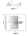
- Figure 1 illustrates how impedance discontinuities or other imperfections can cause a pulsed FM radar transmitter to produce a ghost signal.
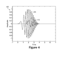
- Figure 2 depicts a pulsed FM radar signal having a low-level reflection.
- Figure 3 illustrates a window function
- Figure 4 illustrates the pulsed FM radar signal of Figure 2 after the application of the window function of Figure 3 .
- Figure 5 depicts an impulse response measurement produced using a conventional pulsed FM radar receiver.
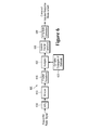
- Figure 6 depicts a simplified, high-level block diagram of a pulsed FM radar receiver according to an embodiment of the present invention.
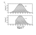
- Figure 7 illustrates the power weightings of a main signal and a ghost signal.
- Figure 8 depicts amplitude correction factors for various ghost signal delays.
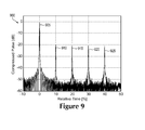
- Figure 9 depicts an impulse response measurement produced using the pulsed FM radar receiver of Figure 6 .
- a secondary or ghost signal is a copy of a main signal that is lower in amplitude than the main signal and delayed relative to it.
- a ghost signal is commonly caused by a low-level internal reflection within a pulsed FM radar transmitter.
- impedance discontinuities or other imperfections within a radar transmitter 100 cause a portion of a main signal 115 transmitted from a radar exciter 105 to reflect back from an amplifier 110 to the radar exciter 105 and then back to the amplifier 110.
- the transmitter 100 also transmits a ghost signal 120, lower in amplitude than the main signal 115 and delayed relative to it.
- the main signal 115 and secondary signal 120 of Figure 1 are depicted as pulsed linear chirp signals 205 and 210 respectively.
- the main signal and ghost signal are depicted as pulsed linear chirp signals, the principles discussed in the following discussion are also applicable to other types of pulsed frequency modulated signals such as pulsed non-linear chirp signals and pulsed phase-coded signals.
- Figure 3 shows a window function 305.
- Figure 5 illustrates the effect of this truncation of a ghost signal after pulse compression.
- An impulse response measurement 500 has a main pulse 505 and ghost pulses 510, 515, 520, and 525 which are delayed by 10%, 20%, 30%, and 40% of the length of the main signal respectively.
- the amplitudes of each of the ghost signals should be reported to be -20 dB of the main signal, however because of the truncation effect discussed above, the amplitudes are reported inaccurately, with the amplitude error increasing with increasing delay. For example, for when the ghost signal is delayed by 10% of the length of the main signal as shown in ghost pulse 510, the amplitude is reported to be about -20 dB.
- the amplitude is reported to be about -23 dB, or about 3dB too low.
- the error due to the truncated ghost signal is about 1.3 dB, and other errors bring the total to about 3 dB.
- Figure 6 shows a pulsed FM radar receiver 600 according to an embodiment of the present invention that provides a more accurate measurement of the amplitude of a secondary response relative to the amplitude of a main response.
- An analog-to-digital converter 605 samples a pulsed FM radar signal to produce a time-domain sample record.
- a window function 610 windows the sample record to produce a windowed sample record.
- the window function 610 may be any form of window function including but not limited to a Taylor window, a Kaiser window, a Blackman-Harris window, or a Hamming window.
- a discrete Fourier transform 615 transforms the windowed sample record into a frequency-domain spectrum.
- a multiplier 620 multiplies the spectrum with the complex conjugate of a frequency-domain estimate of the transmitted pulsed FM radar signal 625, that is, the pulsed FM radar signal that was expected to have been transmitted, to produce a de-spreaded pulse.
- the estimate of the transmitted pulsed FM radar signal may be derived from the received pulsed FM radar signal or it may be generated based on user-specified parameters.
- An inverse discrete Fourier transform 630 transforms the de-spreaded pulse into the time domain to produce a measurement of the impulse response of the pulsed FM radar signal having a main response and a secondary response.
- An amplitude correction 635 calculates an amplitude correction factor and uses it to correct the amplitude of the secondary response to eliminate errors caused by the window function 610.
- Figure 7 shows a power weighting of a main signal 705 and a power weighting of a ghost signal 710 that is delayed by 40% of the length of the main signal.
- a "power weighting" describes the distribution of signal power that results from the application of the window function 305 to a signal.
- the power weighting of the ghost signal 710 is similar to the power weighting of the main signal 705 except that it is truncated by 40% due to the fact that the ghost signal is delayed by 40% of the length of the main signal.
- the amplitude correction factor is equal to the ratio of the integral (that is, the area under the curve) of the power weighting of the main signal 705 to the integral of the power weighting of the ghost signal 710, or in this example, about 1.3 dB.
- the integral of a power weighting is equivalent to the energy of the signal.
- the amplitude correction factor is equal to the ratio of the energy of the main signal to the energy of the ghost signal.
- Figure 8 shows amplitude correction factors 805 for ghost signals having various other delay values.
- a user-selected portion of an impulse response measurement for example, the peak value of a ghost pulse
- every portion of an impulse response measurement is corrected to produce a fully amplitude corrected impulse response measurement 900 as shown in Figure 9 .
- ghost pulses 910, 915, 920, and 925 have amplitudes that are much closer to -20 dB.
- the amplitude correction factor at zero delay that is, the location of the main pulse, is 0 dB.
Landscapes
- Engineering & Computer Science (AREA)
- Radar, Positioning & Navigation (AREA)
- Remote Sensing (AREA)
- Computer Networks & Wireless Communication (AREA)
- Physics & Mathematics (AREA)
- General Physics & Mathematics (AREA)
- Radar Systems Or Details Thereof (AREA)
Abstract
Description
- This application claims the benefit of
U.S. Provisional Application No. 61/233,435, filed August 12, 2009 - The present invention relates to an impulse response measurement for a pulsed frequency modulation (FM) radar signal, and more particularly to an enhanced impulse response measurement that provides a more accurate measurement of the amplitude of a secondary response relative to the amplitude of the main response.
- Pulsed FM radar is a form of radar that detects targets using a pulsed frequency modulated signal. The use of a pulsed frequency modulated signal provides better range resolution and signal-to-noise ratio than other types of signals. Various types of pulsed frequency modulated signals may be used such as a pulsed linear chirp signal (a pulsed sinusoidal signal having a frequency that changes linearly with time), a pulsed non-linear chirp signal (a pulsed sinusoidal signal having a frequency that changes non-linearly with time), and a pulsed phase-coded signal (a pulsed sinusoidal signal that is phase-modulated in accordance with a binary code).
- A pulsed FM radar receiver extracts information about a target from a received pulsed FM radar signal by passing the signal through a matched filter. A matched filter is commonly implemented in the frequency-domain by transforming samples of the received pulsed FM radar signal into a frequency domain spectrum, multiplying the spectrum with the complex conjugate of a frequency-domain estimate of the transmitted pulsed FM radar signal, and transforming the result back into the time-domain. This process "de-spreads" or "compresses" the received pulsed FM radar signal into a narrow pulse, and for this reason it is referred to as "pulse compression." For more information on pulse compression see section 5.3 of "Simulations for Radar Systems Design" by Bassem R. Mahafza and Atef Z. Elsherbeni, Champman & Hall/CRC Press, 2003.
- An "impulse response" of a pulsed FM radar transmitter, also referred to as the "point spread function," is an important quality measurement. The impulse response is the brightness pattern of an image produced after pulse compression from a pulsed FM radar signal that is received directly from a pulsed FM radar transmitter or reflected from a very small point target. A good impulse response has a large value corresponding to the location of a target and small values for all surrounding locations. In other words, the impulse response describes the spatial resolution of a pulsed FM radar system.
- A common impairment of an impulse response is a secondary or "ghost" response. A ghost response is created when a pulsed FM radar transmitter transmits not only an intended or "main" signal but also a "ghost" signal, that is, a copy of the main signal that is lower in amplitude than the main signal and delayed relative to it. A ghost signal is commonly caused by a low-level internal reflection within the pulsed FM radar transmitter. After pulse compression, the ghost signal results in a fictitious pulse at a location not corresponding to a target referred to as a ghost pulse or ghost response. A ghost pulse can interfere with the proper operation of a radar system by giving a false indication of a second target when one is not present, or alternatively, by obscuring the reflection of a second target when one is present. For these reasons, it is important to accurately characterize the impulse response of a pulsed FM radar transmitter and calibrate the corresponding pulsed FM radar receiver accordingly.
- Test and measurement instruments including real-time spectrum analyzers such as the RSA6000 Spectrum Analyzer Series and real-time oscilloscopes such as the DPO/DSA70000B Digital Phosphor Oscilloscope Series, both of which are available from Tektronix, Inc. of Beaverton, Oregon, can be used to measure the impulse response of a pulsed FM radar signal. These test and measurement instruments acquire samples of the pulsed FM radar signal using an acquisition system, perform pulse compression on the acquired samples using software or digital signal processing circuitry, and present a visual image of the resulting impulse response on a display. However, before performing pulse compression, these test and measurement instruments must first apply a window function to the acquired samples in order to avoid truncating the pulsed FM radar signal and thereby generating side-lobes in the frequency domain, an effect referred to as "spectral leakage." The window function is centered about the main signal and thus attenuates the main signal properly. However, if the pulsed FM radar signal includes a ghost signal, then because the ghost signal is delayed relative to the main signal, the ghost signal is not located within the center of the window function but is rather located within a portion of the window function having reduced amplitude, and thus the window function truncates the ghost signal. This truncation of the ghost signal, after pulse compression, causes these test and measurement instruments to inaccurately report the amplitude of the ghost pulse relative to the amplitude of the main pulse.
- What is desired is a method of measuring the impulse response of a pulsed FM radar signal that provides a more accurate measurement of the amplitude of a secondary response relative to the amplitude a main response.
- Accordingly, embodiments of the present invention provide an enhanced method of measuring the impulse response of a pulsed FM radar signal that provides a more accurate measurement of the amplitude of a secondary response relative to the amplitude a main response. A pulsed FM radar signal is sampled to produce a time-domain sample record. The sample record is windowed to produce a windowed sample record. The windowed sample record is transformed into a frequency-domain spectrum. The spectrum is multiplied with the complex conjugate of a frequency-domain estimate of a transmitted pulsed FM radar signal to produce a de-spreaded pulse. The de-spreaded pulse is transformed into the time domain to produce a measurement of the impulse response having a main response and a secondary response. The amplitude of the secondary response is corrected to eliminate errors caused by the windowing.
- The objects, advantages, and other novel features of the present invention are apparent from the following detailed description when read in conjunction with the appended claims and attached drawings.
-
Figure 1 illustrates how impedance discontinuities or other imperfections can cause a pulsed FM radar transmitter to produce a ghost signal. -
Figure 2 depicts a pulsed FM radar signal having a low-level reflection. -
Figure 3 illustrates a window function. -
Figure 4 illustrates the pulsed FM radar signal ofFigure 2 after the application of the window function ofFigure 3 . -
Figure 5 depicts an impulse response measurement produced using a conventional pulsed FM radar receiver. -
Figure 6 depicts a simplified, high-level block diagram of a pulsed FM radar receiver according to an embodiment of the present invention. -
Figure 7 illustrates the power weightings of a main signal and a ghost signal. -
Figure 8 depicts amplitude correction factors for various ghost signal delays. -
Figure 9 depicts an impulse response measurement produced using the pulsed FM radar receiver ofFigure 6 . - To aid understanding, the source of the inaccuracy in the measurement of the amplitude of the secondary response is now discussed in more detail.
- A secondary or ghost signal is a copy of a main signal that is lower in amplitude than the main signal and delayed relative to it. A ghost signal is commonly caused by a low-level internal reflection within a pulsed FM radar transmitter. For example, as shown in
Figure 1 , impedance discontinuities or other imperfections within aradar transmitter 100 cause a portion of amain signal 115 transmitted from aradar exciter 105 to reflect back from anamplifier 110 to the radar exciter 105 and then back to theamplifier 110. Thus, with eachmain signal 115, thetransmitter 100 also transmits aghost signal 120, lower in amplitude than themain signal 115 and delayed relative to it. - In
Figure 2 , themain signal 115 andsecondary signal 120 ofFigure 1 are depicted as pulsedlinear chirp signals ghost signal 210 is lower in amplitude than themain signal 205 and is delayed relative to it by 1.6 / 4 = 40% of the length of themain signal 205. Note that while the main signal and ghost signal are depicted as pulsed linear chirp signals, the principles discussed in the following discussion are also applicable to other types of pulsed frequency modulated signals such as pulsed non-linear chirp signals and pulsed phase-coded signals. -
Figure 3 shows awindow function 305. Thewindow function 305 is centered about themain signal 205, that is, both thewindow function 305 and themain signal 205 are centered at Time = 2. -
Figure 4 illustrates the affect ofwindow function 305 on the pulsedFM radar signal 200. Since thewindow function 305 is centered about themain signal 205, thewindow function 305 attenuates themain signal 205 properly as shown inmain signal 405. However, since theghost signal 210 is delayed relative to themain signal 205, theghost signal 210 is not located within the center of thewindow function 305 but is rather located within a portion of thewindow function 305 having reduced amplitude, and thus thewindow function 305 truncates the trailing portion of theghost signal 210, that is, the portion of theghost signal 210 after Time = 4, as shown inghost signal 410. -
Figure 5 illustrates the effect of this truncation of a ghost signal after pulse compression. Animpulse response measurement 500 has amain pulse 505 andghost pulses ghost pulse 510, the amplitude is reported to be about -20 dB. However, when the ghost signal is delayed by 40% of the length of the main signal as shown inghost pulse 525, the amplitude is reported to be about -23 dB, or about 3dB too low. The error due to the truncated ghost signal is about 1.3 dB, and other errors bring the total to about 3 dB. -
Figure 6 shows a pulsedFM radar receiver 600 according to an embodiment of the present invention that provides a more accurate measurement of the amplitude of a secondary response relative to the amplitude of a main response. An analog-to-digital converter 605 samples a pulsed FM radar signal to produce a time-domain sample record. Awindow function 610 windows the sample record to produce a windowed sample record. Thewindow function 610 may be any form of window function including but not limited to a Taylor window, a Kaiser window, a Blackman-Harris window, or a Hamming window. Adiscrete Fourier transform 615 transforms the windowed sample record into a frequency-domain spectrum. Amultiplier 620 multiplies the spectrum with the complex conjugate of a frequency-domain estimate of the transmitted pulsedFM radar signal 625, that is, the pulsed FM radar signal that was expected to have been transmitted, to produce a de-spreaded pulse. The estimate of the transmitted pulsed FM radar signal may be derived from the received pulsed FM radar signal or it may be generated based on user-specified parameters. An inversediscrete Fourier transform 630 transforms the de-spreaded pulse into the time domain to produce a measurement of the impulse response of the pulsed FM radar signal having a main response and a secondary response. Anamplitude correction 635 calculates an amplitude correction factor and uses it to correct the amplitude of the secondary response to eliminate errors caused by thewindow function 610. - The calculation of an amplitude correction factor for a ghost signal having a particular delay value is illustrated by the following example:
Figure 7 shows a power weighting of amain signal 705 and a power weighting of aghost signal 710 that is delayed by 40% of the length of the main signal. A "power weighting" describes the distribution of signal power that results from the application of thewindow function 305 to a signal. The power weighting of theghost signal 710 is similar to the power weighting of themain signal 705 except that it is truncated by 40% due to the fact that the ghost signal is delayed by 40% of the length of the main signal. The amplitude correction factor is equal to the ratio of the integral (that is, the area under the curve) of the power weighting of themain signal 705 to the integral of the power weighting of theghost signal 710, or in this example, about 1.3 dB. The integral of a power weighting is equivalent to the energy of the signal. Thus, the amplitude correction factor is equal to the ratio of the energy of the main signal to the energy of the ghost signal.Figure 8 showsamplitude correction factors 805 for ghost signals having various other delay values. - In one embodiment of the present invention, a user-selected portion of an impulse response measurement, for example, the peak value of a ghost pulse, is corrected. In an alternative embodiment, every portion of an impulse response measurement is corrected to produce a fully amplitude corrected
impulse response measurement 900 as shown inFigure 9 . Note that in comparison to theuncorrected ghost pulses ghost pulses Figure 8 , the amplitude correction factor at zero delay, that is, the location of the main pulse, is 0 dB. Thus, correcting every portion of an impulse response measurement has no effect on the main response, only the secondary response. - Although the embodiments of the present invention described above use a discrete Fourier transform to transform the windowed sample record into a frequency-domain spectrum, various other embodiments may use other transforms such as a Hartley transform or a chirp-Z transform.
- It will be appreciated from the foregoing discussion that the present invention represents a significant advance in the measurement of an impulse response of a pulsed FM radar signal. Although a specific embodiment of the invention has been illustrated and described for purposes of illustration, it will be understood that various modifications may be made without departing from the spirit and scope of the invention. Accordingly, the invention should not be limited except as by the appended claims.
Claims (18)
- A method of measuring an impulse response of a pulsed frequency modulated radar signal comprising the steps of:sampling the pulsed frequency modulated radar signal to produce a time-domain sample record;windowing the sample record to produce a windowed sample record;transforming the windowed sample record into a frequency-domain spectrum;multiplying the spectrum with a complex conjugate of a frequency-domain estimate of a transmitted pulsed frequency modulated radar signal to produce a de-spreaded pulse;transforming the de-spreaded pulse into a time-domain measurement of the impulse response; andcorrecting an amplitude of the measurement of the impulse response.
- The method of claim 1 wherein the correcting step comprises the steps of:calculating an energy of a main signal;calculating an energy of a secondary signal;calculating a ratio of the energy of the main signal to the energy of the secondary signal; andcorrecting the amplitude of the measurement of the impulse response based on the ratio.
- The method of claim 1 wherein the correcting step comprises the step of correcting a user-selected portion of the measurement of the impulse response.
- The method of claim 1 wherein the correcting step comprises the step of correcting every portion of the measurement of the impulse response.
- The method of claim 1 wherein the windowing step comprises the step of windowing the sample record with a window function selected from the group consisting of a Taylor window, a Kaiser window, a Blackman-Harris window, and a Hamming window.
- The method of claim 1 wherein the step of transforming the windowed sample record into a frequency-domain spectrum comprises the step of transforming the windowed sample record into a frequency-domain spectrum with a transform selected from the group consisting of a discrete Fourier transform, a Hartley transform, and a chirp-Z transform.
- The method of claim 1 wherein the pulsed frequency modulated radar signal comprises a signal selected from the group consisting of a pulsed linear chirp signal, a pulsed non-linear chirp signal, and a pulsed phase-coded signal.
- A test and measurement instrument adapted to perform the method of claim 1.
- The test and measurement instrument of claim 8 wherein the test and measurement is selected from the group consisting of a real-time spectrum analyzer and a real-time oscilloscope.
- A pulsed frequency modulation radar receiver calibrated based on a measurement of an impulse response obtained using the method of claim 1.
- A method of displaying a measurement of an impulse response produced by a test and measurement instrument comprising the steps of:sampling a pulsed frequency modulated radar signal to produce a time-domain sample record;windowing the sample record to produce a windowed sample record;transforming the windowed sample record into a frequency-domain spectrum;multiplying the spectrum with a complex conjugate of a frequency-domain estimate of a transmitted pulsed frequency modulated radar signal to produce a de-spreaded pulse;transforming the de-spreaded pulse into a time-domain measurement of the impulse response;correcting an amplitude of the measurement of the impulse response; anddisplaying the measurement of the impulse response.
- An apparatus comprising:an analog-to-digital converter for sampling a pulsed frequency modulated radar signal to produce a time-domain sample record;a window function for windowing the sample record to produce a windowed sample record;a time-to-frequency transform for transforming the windowed sample record into a frequency-domain spectrum;a multiplier for multiplying the spectrum with a complex conjugate of a frequency-domain estimate of a transmitted pulsed frequency modulated radar signal to produce a de-spreaded pulse;a frequency-to-time transform for transforming the de-spreaded pulse into a time-domain measurement of the impulse response; andan amplitude correction for correcting an amplitude of the measurement of the impulse response based on an amplitude correction factor.
- The apparatus of claim 12 wherein the amplitude correction factor comprises a ratio of an energy of a main signal to an energy of a secondary signal.
- The apparatus of claim 12 wherein the amplitude correction corrects a user-selected portion of the measurement of the impulse response.
- The apparatus of claim 12 wherein the amplitude correction corrects every portion of the measurement of the impulse response.
- The apparatus of claim 12 wherein the window function is a window function selected from the group consisting of a Taylor window, a Kaiser window, a Blackman-Harris window, and a Hamming window.
- The apparatus of claim 12 wherein the time-to-frequency transform is selected from the group consisting of a discrete Fourier transform, a Hartley transform, and a chirp-Z transform.
- The apparatus of claim 12 wherein the pulsed frequency modulated radar signal comprises a signal selected from the group consisting of a pulsed linear chirp signal, a pulsed non-linear chirp signal, and a pulsed phase-coded signal.
Applications Claiming Priority (2)
| Application Number | Priority Date | Filing Date | Title |
|---|---|---|---|
| US23343509P | 2009-08-12 | 2009-08-12 | |
| US12/570,964 US8179305B2 (en) | 2009-08-12 | 2009-09-30 | Enhanced impulse response measurement of an FM radar transmitter pulse |
Publications (2)
| Publication Number | Publication Date |
|---|---|
| EP2290392A1 true EP2290392A1 (en) | 2011-03-02 |
| EP2290392B1 EP2290392B1 (en) | 2013-07-03 |
Family
ID=42983791
Family Applications (1)
| Application Number | Title | Priority Date | Filing Date |
|---|---|---|---|
| EP10170022.7A Active EP2290392B1 (en) | 2009-08-12 | 2010-07-19 | Enhanced impulse response measurement of an FM radar transmitter pulse |
Country Status (3)
| Country | Link |
|---|---|
| US (1) | US8179305B2 (en) |
| EP (1) | EP2290392B1 (en) |
| JP (1) | JP5278773B2 (en) |
Cited By (5)
| Publication number | Priority date | Publication date | Assignee | Title |
|---|---|---|---|---|
| WO2013118121A1 (en) * | 2012-02-11 | 2013-08-15 | Ilan Saul Barak | A microwave contactless heart rate sensor |
| CN105137181A (en) * | 2015-09-15 | 2015-12-09 | 福州大学 | Double-spectrum-line interpolation harmonic analysis algorithm based on Nuttall-Kaiser composite window |
| WO2017052930A1 (en) * | 2015-09-25 | 2017-03-30 | Intel Corporation | Asynchronous on-die eye scope |
| CN110361699A (en) * | 2019-07-23 | 2019-10-22 | 北京工业大学 | A method of ice radar data processing suitable for the Antarctic aerial observation site |
| CN110798255A (en) * | 2019-10-24 | 2020-02-14 | 中国人民解放军32039部队 | Instantaneous distortion signal time domain snapshot system and autonomous trigger capture method |
Families Citing this family (16)
| Publication number | Priority date | Publication date | Assignee | Title |
|---|---|---|---|---|
| CN110055325A (en) | 2011-12-30 | 2019-07-26 | 雅培分子公司 | For the diagnosis of prostate cancer, prognosis and therapeutic/preventative-therapeutic material of assessment and method |
| FR2987453B1 (en) | 2012-02-24 | 2014-04-25 | Thales Sa | RADAR LOCATION SYSTEM AND METHOD |
| US8965290B2 (en) * | 2012-03-29 | 2015-02-24 | General Electric Company | Amplitude enhanced frequency modulation |
| US10371732B2 (en) * | 2012-10-26 | 2019-08-06 | Keysight Technologies, Inc. | Method and system for performing real-time spectral analysis of non-stationary signal |
| US9638789B2 (en) | 2014-01-30 | 2017-05-02 | Infineon Technologies Ag | Method, device and system for processing radar signals |
| JP2017166918A (en) * | 2016-03-15 | 2017-09-21 | 株式会社東芝 | Signal processing apparatus, radar apparatus, signal processing method, and program |
| JP7052526B2 (en) * | 2018-04-23 | 2022-04-12 | 富士通株式会社 | Spectrum analysis program, spectrum analysis method and spectrum analysis device |
| IL259190A (en) * | 2018-05-07 | 2018-06-28 | Arbe Robotics Ltd | System and method for frequency hopping MIMO FMCW imaging radar |
| CN108646072B (en) * | 2018-05-16 | 2019-12-27 | 电子科技大学 | Trigger generating device based on Hamming distance |
| WO2020082316A1 (en) * | 2018-10-26 | 2020-04-30 | 深圳大学 | System and method for processing single sampling radar signal |
| CN109683142B (en) * | 2018-12-04 | 2020-06-09 | 郑州轻工业大学 | Parameter Estimation Method of Triangular Chirp Continuous Signal Based on Differential Envelope Detection |
| US11821977B2 (en) * | 2019-07-10 | 2023-11-21 | Samsung Electronics Co., Ltd. | Target detection and tracking for feature extraction |
| IL278587A (en) | 2020-11-09 | 2022-06-01 | Arbe Robotics Ltd | Efficient direction of arrival estimation using low rank approximation |
| CN114114211B (en) * | 2021-12-03 | 2022-09-06 | 武汉市聚芯微电子有限责任公司 | TDC unit, TDC array and ranging system |
| US12461195B2 (en) * | 2022-09-22 | 2025-11-04 | Nxp B.V. | Near-range interference mitigation for automotive radar system |
| CN120275709B (en) * | 2025-06-05 | 2025-10-28 | 东方电子股份有限公司 | A fast measurement method and device for complex transient frequency of microgrid |
Citations (1)
| Publication number | Priority date | Publication date | Assignee | Title |
|---|---|---|---|---|
| EP1574966A2 (en) * | 2004-03-11 | 2005-09-14 | Kabushiki Kaisha Toshiba | Weight function generating method and signal processing apparatus |
Family Cites Families (5)
| Publication number | Priority date | Publication date | Assignee | Title |
|---|---|---|---|---|
| CA1198805A (en) * | 1981-08-24 | 1985-12-31 | Ronald J. Wyber | Determination of system response |
| JP2550706B2 (en) * | 1989-05-31 | 1996-11-06 | 日本電気株式会社 | Digital pulse compressor |
| JP2669204B2 (en) * | 1991-08-13 | 1997-10-27 | ダイキン工業株式会社 | Exploration equipment |
| JPH0933661A (en) * | 1995-07-25 | 1997-02-07 | Osaka Gas Co Ltd | Correlation type method and device for detection |
| JP2009128278A (en) * | 2007-11-27 | 2009-06-11 | Japan Radio Co Ltd | Pulse compression radar equipment |
-
2009
- 2009-09-30 US US12/570,964 patent/US8179305B2/en active Active
-
2010
- 2010-05-26 JP JP2010120916A patent/JP5278773B2/en active Active
- 2010-07-19 EP EP10170022.7A patent/EP2290392B1/en active Active
Patent Citations (1)
| Publication number | Priority date | Publication date | Assignee | Title |
|---|---|---|---|---|
| EP1574966A2 (en) * | 2004-03-11 | 2005-09-14 | Kabushiki Kaisha Toshiba | Weight function generating method and signal processing apparatus |
Non-Patent Citations (9)
| Title |
|---|
| BELCHER M L ET AL: "Wideband waveform distortion and compensation techniques", PROCEEDINGS OF THE NATIONAL TELESYSTEMS CONFERENCE. ATLANTA, MARCH 26 19910326; 19910326 - 19910327 NEW YORK, IEEE, US, vol. -, 26 March 1991 (1991-03-26), pages 117 - 120, XP010047013, ISBN: 978-0-7803-0062-0, DOI: 10.1109/NTC.1991.147998 * |
| BUCCI N J ET AL: "Testing of Doppler tolerant range sidelobe suppression in pulse compression meteorological radar", RADAR CONFERENCE, 1993., RECORD OF THE 1993 IEEE NATIONAL LYNNFIELD, MA, USA 20-22 APRIL 1993, NEW YORK, NY, USA,IEEE, US, 20 April 1993 (1993-04-20), pages 206 - 211, XP010067877, ISBN: 978-0-7803-0934-0, DOI: 10.1109/NRC.1993.270464 * |
| DEBIN PANG ET AL: "Analysis of Sidelobe Elevation for Polyphase Complementary Codes through the Non-ideal System", SOFTWARE ENGINEERING, ARTIFICIAL INTELLIGENCE, NETWORKING, AND PARALLEL/DISTRIBUTED COMPUTING, 2007. SNPD 2007. EIGHTH ACIS INTERNATIONAL CONFERENCE ON, IEEE, PISCATAWAY, NJ, USA, 1 July 2007 (2007-07-01), pages 717 - 721, XP031125169, ISBN: 978-0-7695-2909-7 * |
| EDWARD C FARNETT ET AL: "Pulse Compression Radar", 1 January 1990, RADAR HANDBOOK (2ND EDITION), NEW YORK, NY : MCGRAW-HILL, US, PAGE(S) 10.1 - 10.39, ISBN: 978-0-07-057913-2, XP007915688 * |
| RODHE & SCHWARZ: "Tackling the Challenges of Pulsed Signal Measurements", APPLICATION NOTE ROHDE AND SCHWARZ,, no. Application Note 1MA124, 18 January 2008 (2008-01-18), pages 1 - 30, XP007915722 * |
| ROHDE & SCHWARZ: "Overview of Tests on Radar Systems and Components", APPLICATION NOTE ROHDE AND SCHWARZ,, no. Application Note 1MA127, 26 June 2008 (2008-06-26), pages 1 - 71, XP007915723 * |
| T. HILL: "Measuring Modern Frequency Chirp Radars", MICROWAVE JOURNAL, SUPPLEMENT, vol. 51, no. 8, August 2008 (2008-08-01), pages 48, XP007915777, Retrieved from the Internet <URL:http://www.mwjournal.com/journal/Print.asp?Id=AR_6265> [retrieved on 20101111] * |
| TEKTONIX: "Advanced Radar Testing", 15 October 2007 (2007-10-15), XP007915776, Retrieved from the Internet <URL:http://www.eumweek.com/2007/PDF/Advanced_Radar_Testing.pdf> [retrieved on 20101111] * |
| TEKTRONIX: "Advanced Radar Analysis: Tools for Measuring Modern Radar", 26 January 2009 (2009-01-26), XP007915790, Retrieved from the Internet <URL:http://www2.tek.com/cmsreplive/tirep/15006/37W_23378_0_LR_Letter_2010.01.08.16.12.29_15006_EN.pdf> [retrieved on 20101116] * |
Cited By (8)
| Publication number | Priority date | Publication date | Assignee | Title |
|---|---|---|---|---|
| WO2013118121A1 (en) * | 2012-02-11 | 2013-08-15 | Ilan Saul Barak | A microwave contactless heart rate sensor |
| US9713434B2 (en) | 2012-02-11 | 2017-07-25 | Sensifree Ltd. | Microwave contactless heart rate sensor |
| CN105137181A (en) * | 2015-09-15 | 2015-12-09 | 福州大学 | Double-spectrum-line interpolation harmonic analysis algorithm based on Nuttall-Kaiser composite window |
| WO2017052930A1 (en) * | 2015-09-25 | 2017-03-30 | Intel Corporation | Asynchronous on-die eye scope |
| US9922248B2 (en) | 2015-09-25 | 2018-03-20 | Intel Corporation | Asynchronous on-die eye scope |
| CN107923941A (en) * | 2015-09-25 | 2018-04-17 | 英特尔公司 | Eyes visualizer on asynchronous tube core |
| CN110361699A (en) * | 2019-07-23 | 2019-10-22 | 北京工业大学 | A method of ice radar data processing suitable for the Antarctic aerial observation site |
| CN110798255A (en) * | 2019-10-24 | 2020-02-14 | 中国人民解放军32039部队 | Instantaneous distortion signal time domain snapshot system and autonomous trigger capture method |
Also Published As
| Publication number | Publication date |
|---|---|
| JP2011039033A (en) | 2011-02-24 |
| US8179305B2 (en) | 2012-05-15 |
| EP2290392B1 (en) | 2013-07-03 |
| JP5278773B2 (en) | 2013-09-04 |
| US20110037643A1 (en) | 2011-02-17 |
Similar Documents
| Publication | Publication Date | Title |
|---|---|---|
| US8179305B2 (en) | Enhanced impulse response measurement of an FM radar transmitter pulse | |
| CN112965037B (en) | Radar signal waveform uncertainty test system | |
| EP3812790A1 (en) | Device, system and method for calibration of radar target simulators | |
| US20040027138A1 (en) | Oscilloscope based return loss analyzer | |
| US10914782B2 (en) | Test system and test method for testing a device under test | |
| CN104316913A (en) | Multichannel receiver real-time calibration device and calibration and error compensation method | |
| CN110261830B (en) | Performance calibrator for radar echo simulator | |
| CN110850380A (en) | Method for realizing weather radar digital calibration unit | |
| US6484124B1 (en) | System for measurement of selected performance characteristics of microwave components | |
| US11898927B2 (en) | Real-equivalent-time oscilloscope with time domain reflectometer | |
| CN117269907B (en) | DRFM-based high-precision continuous wave radar target simulation method and device | |
| US10509064B2 (en) | Impedance measurement through waveform monitoring | |
| CN115078854B (en) | Rectangular pulse modulation periodic signal radiation field intensity measurement method | |
| US9081053B2 (en) | Using continuous sweep frequencies in a system frequency response test | |
| Li et al. | Software-defined calibration for FMCW phased-array radar | |
| CN102375139B (en) | The impulse response measurement of the enhancing of FM radar transmitter pulse | |
| CN114910707A (en) | Root mean square value detection measurement method for periodic pulse radiation field intensity | |
| CN111913161B (en) | Method for improving NLFM waveform radar target angle measurement precision | |
| Oliveira et al. | Primary reciprocity-based method for calibration of hydrophone magnitude and phase sensitivity: Complete tests at frequencies from 1 to 7 MHz | |
| CN110907879B (en) | Calibration method of interturn voltage-withstanding tester | |
| EP2026480B1 (en) | Method for measuring the trigger to frame time accuracy in measurement receivers | |
| CN111551905A (en) | Scattering point delay parameter calibration method and system | |
| Zirizzotti et al. | AISP programmable ionosonde | |
| CN110687362A (en) | Real-time phase noise testing method | |
| Kiliç et al. | System RF performance analysis using PDW on electronic warfare systems |
Legal Events
| Date | Code | Title | Description |
|---|---|---|---|
| PUAI | Public reference made under article 153(3) epc to a published international application that has entered the european phase |
Free format text: ORIGINAL CODE: 0009012 |
|
| AK | Designated contracting states |
Kind code of ref document: A1 Designated state(s): AL AT BE BG CH CY CZ DE DK EE ES FI FR GB GR HR HU IE IS IT LI LT LU LV MC MK MT NL NO PL PT RO SE SI SK SM TR |
|
| AX | Request for extension of the european patent |
Extension state: BA ME RS |
|
| 17P | Request for examination filed |
Effective date: 20110902 |
|
| GRAP | Despatch of communication of intention to grant a patent |
Free format text: ORIGINAL CODE: EPIDOSNIGR1 |
|
| RIC1 | Information provided on ipc code assigned before grant |
Ipc: G01S 7/285 20060101ALN20130221BHEP Ipc: G01S 7/40 20060101AFI20130221BHEP Ipc: G01S 13/28 20060101ALN20130221BHEP Ipc: G01R 19/04 20060101ALI20130221BHEP Ipc: G01R 29/02 20060101ALI20130221BHEP |
|
| RIC1 | Information provided on ipc code assigned before grant |
Ipc: G01R 19/04 20060101ALI20130307BHEP Ipc: G01S 13/28 20060101ALN20130307BHEP Ipc: G01S 7/285 20060101ALN20130307BHEP Ipc: G01S 7/40 20060101AFI20130307BHEP Ipc: G01R 29/02 20060101ALI20130307BHEP |
|
| GRAS | Grant fee paid |
Free format text: ORIGINAL CODE: EPIDOSNIGR3 |
|
| GRAA | (expected) grant |
Free format text: ORIGINAL CODE: 0009210 |
|
| AK | Designated contracting states |
Kind code of ref document: B1 Designated state(s): AL AT BE BG CH CY CZ DE DK EE ES FI FR GB GR HR HU IE IS IT LI LT LU LV MC MK MT NL NO PL PT RO SE SI SK SM TR |
|
| REG | Reference to a national code |
Ref country code: GB Ref legal event code: FG4D |
|
| REG | Reference to a national code |
Ref country code: AT Ref legal event code: REF Ref document number: 620072 Country of ref document: AT Kind code of ref document: T Effective date: 20130715 Ref country code: CH Ref legal event code: EP |
|
| REG | Reference to a national code |
Ref country code: IE Ref legal event code: FG4D |
|
| REG | Reference to a national code |
Ref country code: DE Ref legal event code: R096 Ref document number: 602010008160 Country of ref document: DE Effective date: 20130829 |
|
| PG25 | Lapsed in a contracting state [announced via postgrant information from national office to epo] |
Ref country code: SI Free format text: LAPSE BECAUSE OF FAILURE TO SUBMIT A TRANSLATION OF THE DESCRIPTION OR TO PAY THE FEE WITHIN THE PRESCRIBED TIME-LIMIT Effective date: 20130703 |
|
| REG | Reference to a national code |
Ref country code: AT Ref legal event code: MK05 Ref document number: 620072 Country of ref document: AT Kind code of ref document: T Effective date: 20130703 |
|
| REG | Reference to a national code |
Ref country code: NL Ref legal event code: VDEP Effective date: 20130703 |
|
| REG | Reference to a national code |
Ref country code: LT Ref legal event code: MG4D |
|
| PG25 | Lapsed in a contracting state [announced via postgrant information from national office to epo] |
Ref country code: LT Free format text: LAPSE BECAUSE OF FAILURE TO SUBMIT A TRANSLATION OF THE DESCRIPTION OR TO PAY THE FEE WITHIN THE PRESCRIBED TIME-LIMIT Effective date: 20130703 Ref country code: CY Free format text: LAPSE BECAUSE OF FAILURE TO SUBMIT A TRANSLATION OF THE DESCRIPTION OR TO PAY THE FEE WITHIN THE PRESCRIBED TIME-LIMIT Effective date: 20130710 Ref country code: IS Free format text: LAPSE BECAUSE OF FAILURE TO SUBMIT A TRANSLATION OF THE DESCRIPTION OR TO PAY THE FEE WITHIN THE PRESCRIBED TIME-LIMIT Effective date: 20131103 Ref country code: HR Free format text: LAPSE BECAUSE OF FAILURE TO SUBMIT A TRANSLATION OF THE DESCRIPTION OR TO PAY THE FEE WITHIN THE PRESCRIBED TIME-LIMIT Effective date: 20130703 Ref country code: SE Free format text: LAPSE BECAUSE OF FAILURE TO SUBMIT A TRANSLATION OF THE DESCRIPTION OR TO PAY THE FEE WITHIN THE PRESCRIBED TIME-LIMIT Effective date: 20130703 Ref country code: BE Free format text: LAPSE BECAUSE OF FAILURE TO SUBMIT A TRANSLATION OF THE DESCRIPTION OR TO PAY THE FEE WITHIN THE PRESCRIBED TIME-LIMIT Effective date: 20130703 Ref country code: NO Free format text: LAPSE BECAUSE OF FAILURE TO SUBMIT A TRANSLATION OF THE DESCRIPTION OR TO PAY THE FEE WITHIN THE PRESCRIBED TIME-LIMIT Effective date: 20131003 Ref country code: AT Free format text: LAPSE BECAUSE OF FAILURE TO SUBMIT A TRANSLATION OF THE DESCRIPTION OR TO PAY THE FEE WITHIN THE PRESCRIBED TIME-LIMIT Effective date: 20130703 Ref country code: PT Free format text: LAPSE BECAUSE OF FAILURE TO SUBMIT A TRANSLATION OF THE DESCRIPTION OR TO PAY THE FEE WITHIN THE PRESCRIBED TIME-LIMIT Effective date: 20131104 |
|
| PG25 | Lapsed in a contracting state [announced via postgrant information from national office to epo] |
Ref country code: GR Free format text: LAPSE BECAUSE OF FAILURE TO SUBMIT A TRANSLATION OF THE DESCRIPTION OR TO PAY THE FEE WITHIN THE PRESCRIBED TIME-LIMIT Effective date: 20131004 Ref country code: PL Free format text: LAPSE BECAUSE OF FAILURE TO SUBMIT A TRANSLATION OF THE DESCRIPTION OR TO PAY THE FEE WITHIN THE PRESCRIBED TIME-LIMIT Effective date: 20130703 Ref country code: ES Free format text: LAPSE BECAUSE OF FAILURE TO SUBMIT A TRANSLATION OF THE DESCRIPTION OR TO PAY THE FEE WITHIN THE PRESCRIBED TIME-LIMIT Effective date: 20131014 Ref country code: FI Free format text: LAPSE BECAUSE OF FAILURE TO SUBMIT A TRANSLATION OF THE DESCRIPTION OR TO PAY THE FEE WITHIN THE PRESCRIBED TIME-LIMIT Effective date: 20130703 Ref country code: LV Free format text: LAPSE BECAUSE OF FAILURE TO SUBMIT A TRANSLATION OF THE DESCRIPTION OR TO PAY THE FEE WITHIN THE PRESCRIBED TIME-LIMIT Effective date: 20130703 Ref country code: NL Free format text: LAPSE BECAUSE OF FAILURE TO SUBMIT A TRANSLATION OF THE DESCRIPTION OR TO PAY THE FEE WITHIN THE PRESCRIBED TIME-LIMIT Effective date: 20130703 |
|
| PG25 | Lapsed in a contracting state [announced via postgrant information from national office to epo] |
Ref country code: CY Free format text: LAPSE BECAUSE OF FAILURE TO SUBMIT A TRANSLATION OF THE DESCRIPTION OR TO PAY THE FEE WITHIN THE PRESCRIBED TIME-LIMIT Effective date: 20130703 |
|
| REG | Reference to a national code |
Ref country code: IE Ref legal event code: MM4A |
|
| PG25 | Lapsed in a contracting state [announced via postgrant information from national office to epo] |
Ref country code: RO Free format text: LAPSE BECAUSE OF FAILURE TO SUBMIT A TRANSLATION OF THE DESCRIPTION OR TO PAY THE FEE WITHIN THE PRESCRIBED TIME-LIMIT Effective date: 20130703 Ref country code: DK Free format text: LAPSE BECAUSE OF FAILURE TO SUBMIT A TRANSLATION OF THE DESCRIPTION OR TO PAY THE FEE WITHIN THE PRESCRIBED TIME-LIMIT Effective date: 20130703 Ref country code: EE Free format text: LAPSE BECAUSE OF FAILURE TO SUBMIT A TRANSLATION OF THE DESCRIPTION OR TO PAY THE FEE WITHIN THE PRESCRIBED TIME-LIMIT Effective date: 20130703 Ref country code: SK Free format text: LAPSE BECAUSE OF FAILURE TO SUBMIT A TRANSLATION OF THE DESCRIPTION OR TO PAY THE FEE WITHIN THE PRESCRIBED TIME-LIMIT Effective date: 20130703 Ref country code: MC Free format text: LAPSE BECAUSE OF FAILURE TO SUBMIT A TRANSLATION OF THE DESCRIPTION OR TO PAY THE FEE WITHIN THE PRESCRIBED TIME-LIMIT Effective date: 20130703 Ref country code: CZ Free format text: LAPSE BECAUSE OF FAILURE TO SUBMIT A TRANSLATION OF THE DESCRIPTION OR TO PAY THE FEE WITHIN THE PRESCRIBED TIME-LIMIT Effective date: 20130703 |
|
| PLBE | No opposition filed within time limit |
Free format text: ORIGINAL CODE: 0009261 |
|
| STAA | Information on the status of an ep patent application or granted ep patent |
Free format text: STATUS: NO OPPOSITION FILED WITHIN TIME LIMIT |
|
| 26N | No opposition filed |
Effective date: 20140404 |
|
| REG | Reference to a national code |
Ref country code: DE Ref legal event code: R097 Ref document number: 602010008160 Country of ref document: DE Effective date: 20140404 |
|
| PG25 | Lapsed in a contracting state [announced via postgrant information from national office to epo] |
Ref country code: IE Free format text: LAPSE BECAUSE OF NON-PAYMENT OF DUE FEES Effective date: 20130719 |
|
| REG | Reference to a national code |
Ref country code: CH Ref legal event code: PL |
|
| PG25 | Lapsed in a contracting state [announced via postgrant information from national office to epo] |
Ref country code: CH Free format text: LAPSE BECAUSE OF NON-PAYMENT OF DUE FEES Effective date: 20140731 Ref country code: LI Free format text: LAPSE BECAUSE OF NON-PAYMENT OF DUE FEES Effective date: 20140731 |
|
| PG25 | Lapsed in a contracting state [announced via postgrant information from national office to epo] |
Ref country code: SM Free format text: LAPSE BECAUSE OF FAILURE TO SUBMIT A TRANSLATION OF THE DESCRIPTION OR TO PAY THE FEE WITHIN THE PRESCRIBED TIME-LIMIT Effective date: 20130703 |
|
| PG25 | Lapsed in a contracting state [announced via postgrant information from national office to epo] |
Ref country code: MT Free format text: LAPSE BECAUSE OF FAILURE TO SUBMIT A TRANSLATION OF THE DESCRIPTION OR TO PAY THE FEE WITHIN THE PRESCRIBED TIME-LIMIT Effective date: 20130703 Ref country code: TR Free format text: LAPSE BECAUSE OF FAILURE TO SUBMIT A TRANSLATION OF THE DESCRIPTION OR TO PAY THE FEE WITHIN THE PRESCRIBED TIME-LIMIT Effective date: 20130703 |
|
| REG | Reference to a national code |
Ref country code: FR Ref legal event code: PLFP Year of fee payment: 6 |
|
| PG25 | Lapsed in a contracting state [announced via postgrant information from national office to epo] |
Ref country code: MK Free format text: LAPSE BECAUSE OF FAILURE TO SUBMIT A TRANSLATION OF THE DESCRIPTION OR TO PAY THE FEE WITHIN THE PRESCRIBED TIME-LIMIT Effective date: 20130703 Ref country code: LU Free format text: LAPSE BECAUSE OF NON-PAYMENT OF DUE FEES Effective date: 20130719 Ref country code: HU Free format text: LAPSE BECAUSE OF FAILURE TO SUBMIT A TRANSLATION OF THE DESCRIPTION OR TO PAY THE FEE WITHIN THE PRESCRIBED TIME-LIMIT; INVALID AB INITIO Effective date: 20100719 Ref country code: BG Free format text: LAPSE BECAUSE OF FAILURE TO SUBMIT A TRANSLATION OF THE DESCRIPTION OR TO PAY THE FEE WITHIN THE PRESCRIBED TIME-LIMIT Effective date: 20130703 |
|
| REG | Reference to a national code |
Ref country code: FR Ref legal event code: PLFP Year of fee payment: 7 |
|
| REG | Reference to a national code |
Ref country code: FR Ref legal event code: PLFP Year of fee payment: 8 |
|
| PGFP | Annual fee paid to national office [announced via postgrant information from national office to epo] |
Ref country code: IT Payment date: 20170725 Year of fee payment: 8 Ref country code: FR Payment date: 20170726 Year of fee payment: 8 |
|
| PG25 | Lapsed in a contracting state [announced via postgrant information from national office to epo] |
Ref country code: AL Free format text: LAPSE BECAUSE OF FAILURE TO SUBMIT A TRANSLATION OF THE DESCRIPTION OR TO PAY THE FEE WITHIN THE PRESCRIBED TIME-LIMIT Effective date: 20130703 |
|
| PGFP | Annual fee paid to national office [announced via postgrant information from national office to epo] |
Ref country code: GB Payment date: 20180727 Year of fee payment: 9 |
|
| PG25 | Lapsed in a contracting state [announced via postgrant information from national office to epo] |
Ref country code: FR Free format text: LAPSE BECAUSE OF NON-PAYMENT OF DUE FEES Effective date: 20180731 |
|
| PG25 | Lapsed in a contracting state [announced via postgrant information from national office to epo] |
Ref country code: IT Free format text: LAPSE BECAUSE OF NON-PAYMENT OF DUE FEES Effective date: 20180719 |
|
| GBPC | Gb: european patent ceased through non-payment of renewal fee |
Effective date: 20190719 |
|
| PG25 | Lapsed in a contracting state [announced via postgrant information from national office to epo] |
Ref country code: GB Free format text: LAPSE BECAUSE OF NON-PAYMENT OF DUE FEES Effective date: 20190719 |
|
| P01 | Opt-out of the competence of the unified patent court (upc) registered |
Effective date: 20230530 |
|
| PGFP | Annual fee paid to national office [announced via postgrant information from national office to epo] |
Ref country code: DE Payment date: 20250729 Year of fee payment: 16 |