EP2290207A2 - Cambered aero-engine inlet - Google Patents
Cambered aero-engine inlet Download PDFInfo
- Publication number
- EP2290207A2 EP2290207A2 EP20100003605 EP10003605A EP2290207A2 EP 2290207 A2 EP2290207 A2 EP 2290207A2 EP 20100003605 EP20100003605 EP 20100003605 EP 10003605 A EP10003605 A EP 10003605A EP 2290207 A2 EP2290207 A2 EP 2290207A2
- Authority
- EP
- European Patent Office
- Prior art keywords
- centerline axis
- inlet
- engine
- fan
- profile
- Prior art date
- Legal status (The legal status is an assumption and is not a legal conclusion. Google has not performed a legal analysis and makes no representation as to the accuracy of the status listed.)
- Granted
Links
Images


Classifications
-
- F—MECHANICAL ENGINEERING; LIGHTING; HEATING; WEAPONS; BLASTING
- F02—COMBUSTION ENGINES; HOT-GAS OR COMBUSTION-PRODUCT ENGINE PLANTS
- F02C—GAS-TURBINE PLANTS; AIR INTAKES FOR JET-PROPULSION PLANTS; CONTROLLING FUEL SUPPLY IN AIR-BREATHING JET-PROPULSION PLANTS
- F02C7/00—Features, components parts, details or accessories, not provided for in, or of interest apart form groups F02C1/00 - F02C6/00; Air intakes for jet-propulsion plants
- F02C7/04—Air intakes for gas-turbine plants or jet-propulsion plants
-
- F—MECHANICAL ENGINEERING; LIGHTING; HEATING; WEAPONS; BLASTING
- F02—COMBUSTION ENGINES; HOT-GAS OR COMBUSTION-PRODUCT ENGINE PLANTS
- F02C—GAS-TURBINE PLANTS; AIR INTAKES FOR JET-PROPULSION PLANTS; CONTROLLING FUEL SUPPLY IN AIR-BREATHING JET-PROPULSION PLANTS
- F02C7/00—Features, components parts, details or accessories, not provided for in, or of interest apart form groups F02C1/00 - F02C6/00; Air intakes for jet-propulsion plants
- F02C7/04—Air intakes for gas-turbine plants or jet-propulsion plants
- F02C7/042—Air intakes for gas-turbine plants or jet-propulsion plants having variable geometry
-
- Y—GENERAL TAGGING OF NEW TECHNOLOGICAL DEVELOPMENTS; GENERAL TAGGING OF CROSS-SECTIONAL TECHNOLOGIES SPANNING OVER SEVERAL SECTIONS OF THE IPC; TECHNICAL SUBJECTS COVERED BY FORMER USPC CROSS-REFERENCE ART COLLECTIONS [XRACs] AND DIGESTS
- Y10—TECHNICAL SUBJECTS COVERED BY FORMER USPC
- Y10T—TECHNICAL SUBJECTS COVERED BY FORMER US CLASSIFICATION
- Y10T137/00—Fluid handling
- Y10T137/0536—Highspeed fluid intake means [e.g., jet engine intake]
-
- Y—GENERAL TAGGING OF NEW TECHNOLOGICAL DEVELOPMENTS; GENERAL TAGGING OF CROSS-SECTIONAL TECHNOLOGIES SPANNING OVER SEVERAL SECTIONS OF THE IPC; TECHNICAL SUBJECTS COVERED BY FORMER USPC CROSS-REFERENCE ART COLLECTIONS [XRACs] AND DIGESTS
- Y10—TECHNICAL SUBJECTS COVERED BY FORMER USPC
- Y10T—TECHNICAL SUBJECTS COVERED BY FORMER US CLASSIFICATION
- Y10T137/00—Fluid handling
- Y10T137/0536—Highspeed fluid intake means [e.g., jet engine intake]
- Y10T137/0645—With condition responsive control means
Definitions
- the present invention relates generally to gas turbine engines, and more particularly, to turbofan aircraft engines.
- turbofan engines One of the primary design criteria for aircraft turbofan engines is to propel an aircraft in flight with maximum efficiency, thereby reducing fuel consumption.
- turbofan engines are continually being developed and improved to maximize thrust capability with the greatest aerodynamic efficiency possible.
- One of the components of the turbofan engine is an array of fan blades, which are positioned adjacent the forward portion of the turbofan adjacent the turbofan's inlet.
- the fan blades produce thrust, and thus, are typically designed to maximize the aerodynamic loading and the amount of propulsion thrust generated thereby during operation.
- fan loading is limited by stall, flutter, or other instability parameters of the air being pressurized.
- Fan stall margin is a fundamental design requirement for the turbofan and is affected by aerodynamic fan loading.
- a major factor affecting the aerodynamic loading of the fan is the geometry of the inlet upstream of the fan. Aircraft wings are known to induce an upwash velocity in airflow in the inlet.
- conventional inlets do not account sufficiently for the vertical component (vector) of the airflow.
- the circumferential vector of the airflow causes the fan to operate with different circumferential sectors having different flow-pressure ratio characteristics.
- the circumferential vector of the inlet airflow manifests itself as a swirl velocity along the face of the fan blades.
- the swirl velocity is in a direction counter to the direction of rotation of the fan along at least a portion of the fan face.
- the swirl velocity has a destabilizing effect on the flow condition over sector(s) of the fan, and thus, degrades the stall margin of the fan.
- the different flow-pressure ratio characteristics on the fan produce a circumferential variation in total pressure at the inlet to the core stream of the turbofan.
- the total pressure variation has a destabilizing effect on the operation of the low pressure compressor and high pressure compressor sections of the turbofan.
- An inlet of a nacelle for channeling inlet airflow to a fan of a gas turbine engine includes a forward lip and an inner surface.
- the forward lip extends around a centerline axis of the engine and is adapted to accommodate a flow angle of incoming airflow.
- the inner surface extends from the forward lip along the centerline axis of the engine to adjacent the fan.
- the inner surface has a first profile above the centerline axis of the engine and a second profile below the centerline axis of the engine. The first profile and the second profile are adapted to define an inlet centerline axis that extends below the centerline axis of the engine at a face of the fan.
- FIG. 1 is a schematic representation of a portion of an aircraft having a wing mounted gas turbine engine including a nacelle inlet.
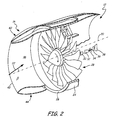
- FIG. 2 is a partially schematic partially sectional view of the turbofan portion of the gas turbine engine of FIG. 1 .
- FIG. 3 is a schematic sectional view of the nacelle inlet and a fan shown in FIG. 2 .
- FIG. 4 is a diagrammatic view of the front of the fan showing a decrease in an airflow swirl velocity.
- FIG. 1 shows an exemplary portion of an aircraft 10 having at least one gas turbine engine 12 mounted to one wing 14 thereof.
- the engine 12 includes a nacelle 16 that defines an inlet 18.
- the engine 12 is disposed around an engine centerline axis 20.
- the nacelle 16 is an aerodynamic structure that surrounds at least a portion of the engine 12 and forms an inlet 18 thereto.
- the nacelle 16 channels free stream airflow 22 through the inlet 18 to the internal components of the engine 12.
- Adjacent to the inlet 18 and wing 14, the free stream airflow 22 has an upwash angle ⁇ with respect to the engine centerline axis 20.
- the upwash angle ⁇ is due to the aerodynamic effects of the wing 14.
- the upwash angle ⁇ exists in the inlet airflow after the free stream airflow 22 enters the inlet 18.
- the portion of the nacelle 16 that defines the inlet 18 is adapted to align the upwash angle ⁇ with the engine centerline axis 20 at a fan within the engine 12.
- the alignment of the upwash angle ⁇ with the engine centerline axis 20 reduces or eliminates the vertical vector of the inlet airflow that causes a swirl velocity along the face of the fan blades.
- the reduction or elimination of the swirl velocity allows components of the engine 12 to better meet fan stall margin requirements and improves aerodynamic fan loading.
- FIG. 2 shows a section of the turbofan portion of the gas turbine engine 12.
- the engine 12 includes a fan case 24 having a fan case flange 26, a fan 28, a low pressure compressor 30, a high pressure compressor 32, a combustor 34, a high pressure turbine 36, and a low pressure turbine 38.
- the nacelle 16 includes forward lip portion 40, a crown portion 42, a keel portion 44 and an inner surface 46.
- a section of the nacelle 16 has been removed along a vertical plane extending through top dead center and bottom dead center thereof.
- the nacelle 16 connects to and extends around the axisymmetrical fan case 24.
- the fan case flange 26 extends generally radially outward from the forward portion of the fan case 24 to connect to the nacelle 16.
- the portion of the nacelle 16 that defines the inlet 18 extends forward of the fan case 24 and fan case flange 26.
- the fan 28 is rotationally mounted within the fan case 24 and is co-aligned along the same axis as the engine centerline axis 20.
- the low pressure compressor 30, high pressure compressor 32, combustor 34, high pressure turbine 36, and low pressure turbine 38 extend in series axially downstream (rearward) of the fan 28.
- the forward lip 40 of the nacelle 16 defines the forward portion of the inlet 18.
- the forward lip 40 extends around the engine centerline axis 20.
- the nacelle 16 can generally be divided into the crown portion 42, which extends generally above the engine centerline axis 20, and the keel portion 44, which extends generally below the engine centerline axis 20.
- the crown portion 42 is asymmetrical with respect to the keel portion 44 but both together integrally extend around the engine centerline axis 20.
- the keel 44 can be dropped (i.e. adapted to have its portion of the forward lip 40 be disposed to the rearward of the forward lip 40 of the crown portion 42) such that the forward lip 40 does not extend along a vertical plane. This arrangement allows the inlet 18 to accommodate the upwash angle ⁇ of incoming airflow.
- the inner surface 46 of the nacelle 16 defines a portion of the inlet 18 which also extends through the annular fan case 24 to the fan case flange 26. As will be discussed subsequently, the inner surface 46 of the nacelle 16 is profiled on both the crown portion 42 and the keel portion 44 to align the upwash of inlet airflow with the engine centerline axis 20 at the face of the fan 28.
- the free stream airflow 22 enters the inlet 18, is aligned by the geometry of the nacelle 16, and is pressurized by the fan 28. A portion of the airflow is channeled to engine core where it is pressurized, mixed with fuel/combusted, and expanded before being expelled from the engine 12. A second portion of the airflow bypasses the engine core and is expelled from an outlet portion of the nacelle 16.
- the air After being pressurized in the low pressure compressor 30 and high pressure compressor 32, the air is mixed with fuel in the combustor 34 for generating hot combustion gases. From the combustor 32, the gases and airflow are discharged downstream into the high pressure turbine 34. The high pressure turbine 34 and low pressure turbine 36 in turn receive the combusted gases and extract energy therefrom. The high pressure turbine 34 is joined by a rotor or shaft (not shown) to the high pressure compressor 32 and the fan 28 for powering these components during operation. The combination of thrust produced from the fan 28 and the components of the engine core propel the aircraft 10 in flight ( FIG. 1 ).
- FIG. 3 shows a schematic sectional view of one embodiment of the nacelle 16 and the fan 28.
- the axially forward most extent of the fan case flange 26 is denoted by a fan case flange plane 48.
- the axial forward most portion of the fan 28 is indicated by a fan face plane 50.
- the inner surface 46 of the nacelle 16 includes a first profile 52 and a second profile 54.
- the first profile 52 has a generally convex forward section 52F that transitions to a generally concave rearward section 52R (when observed from the engine centerline axis 20) at inflection point 53.
- the second profile 54 has a generally convex forward section 54F that transitions to a generally concave rearward section 54R (when viewed from the engine centerline axis 20) at inflection point 55.
- the geometry of the inner surface 46 of the nacelle 16 defines an inlet centerline axis 56.
- the forward lip 40 of the nacelle 16 defines the orifice of the inlet 18.
- the forward lip 40 extends around the engine centerline axis 20.
- the crown portion 42 of the nacelle 16 extends above the engine centerline axis 20.
- the keel portion 44 of the nacelle 16 extends below the engine centerline axis 20. Together both the crown portion 42 and the keel portion 44 form the inner surface 46.
- the inner surface 46 defines the inlet 18, which extends axially along the engine centerline axis 20 from the forward lip 40 to the fan case flange plane 48.
- the inner surface 46 also defines the inlet centerline axis 56 which approximates the geometric center of inlet 18.
- the shape of the inner surface 46 above the engine centerline axis 20 is asymmetrical with respect to the shape of the inner surface 46 below the engine centerline axis 20. More particularly, the inner surface 46 above the engine centerline axis 20 is shaped with the first profile 52, which extends generally axially along the engine centerline axis 20 from the forward lip 40 to at least the fan case flange plane 48. The first profile 52 varies in the radial distance it is disposed from the engine centerline axis 20. Similarly, the inner surface 46 below the engine centerline axis 20 is shaped with the second profile 54, which extends generally axially along the engine centerline axis 20 from the forward lip 40 to at least the fan case flange plane 48. The second profile 54 varies in the radial distance it is disposed from the engine centerline axis 20.
- the radial distance the first profile 52 is disposed from the engine centerline axis 20 differs from the radial distance the second profile 54 is disposed from the engine centerline axis 20.
- the volume and cross sectional area of the inlet 18 above the engine centerline axis 20 generally differs from the volume and cross sectional area of the inlet 18 below the engine centerline axis 20.
- the difference in geometry between the first and second profiles 52 and 54 is approximated by the inlet centerline axis 56 (which approximates the geometric center of the inlet 18), which has a cambered shape with respect to the engine centerline axis 20.
- the inflection point 53 of the first profile 52 is radially and axially offset along the engine centerline axis 20 from the inflection point 55 of the second profile 54. More particularly, the convex forward section 54F (when viewed from the engine centerline axis 20) of the second profile 54 extends further rearward toward the fan face plane 50 than does the convex forward section 52F of the first profile 52. Terms such as “forward,” “rearward,” “upstream,” and “downstream” are defined by the direction of airflow 22 within the inlet 18. Thus, the concave rearward section 52R (when viewed from the engine centerline axis 20) of the first profile 52 extends further forward away from the fan face plane 50 than does the concave rearward section 54R of the second profile 54.
- This geometry disposes the inflection point 55 between the convex and concave sections (54F and 54R) of the second profile 54 closer to the face of the fan 28 than the inflection point 53 between the convex and concave sections (52F and 54R) of the first profile 52.
- the convex forward section 54F of the second profile 54 is geometrically accentuated relative to the concave rearward section 54R of the second profile 54 and the convex forward section 52F of the first profile 52.
- the concave rearward section 52R of the first profile 52 is geometrically accentuated relative to the convex forward section 52F of the first profile 52 and the concave rearward section 54R or the second profile 54.
- the precise interrelation of profiles 52 and 54 i.e. the precise geometric accentuation of the concave/convex sections 52F, 52R, 54F, 54R relative to one another) is achieved through computational fluid mechanics.
- the different axial and radial geometry of the inner surface 46 above the engine centerline axis 20 with respect to the axial and radial geometry of the inner surface 46 below the engine centerline axis 20 cambers the inlet centerline axis 56 with respect to the engine centerline axis 20.
- the geometry of the first profile 52 with respect to the second profile 54 disposes the inlet centerline axis 56 radially above the engine centerline axis 20 immediately to the rear of the forward lip 40 within the inlet 18.
- the inlet centerline axis 56 extends above the engine centerline axis 20 for a portion of its axial extent within the inlet 18.
- the geometry of the first profile 52 with respect to the second profile 54 about the engine centerline axis 20 causes the inlet centerline axis 56 to have an acute descending depression angle ⁇ at the fan case flange plane 48.
- the acute depression angle ⁇ the inlet centerline axis 56 forms with respect to the engine centerline axis 20 offsets any residual upwash of the airflow 22 entering the inlet 18.
- the geometry of the inner surface 46 allows the airflow 22 in the inlet 18 to substantially align with the engine centerline axis 20 (which is also the rotational axis of the fan 28) at the face of the fan 28.
- the inlet centerline axis 56 is coincident with the engine centerline axis 20 at the fan case flange plane 48.
- the inlet centerline axis 56 can merge with or be coincident with the engine centerline axis 20 forward (as defined by the direction of airflow 22) of the fan case flange plane 48.
- the inlet centerline axis extends below the centerline axis of the engine at the face of the fan.
- an airflow 22 swirl velocity on the face of the fan 28 at 90° and 270° to top dead center (TDC) is reduced or eliminated by offsetting the first profile 52 with respect to the second profile 54.
- TDC top dead center
- the elimination of the swirl velocity occurs because the inlet centerline axis 56 extends below the engine centerline axis 20 and aligns the airflow 22 in the inlet 18 with the engine centerline axis 20 at the face of the fan 28.
- the swirl velocity at 270° (measured from TDC of the fan 28), co-rotating with the fan 28 (when the fan 28 is rotating in a clockwise direction), and the swirl velocity at 90° counter-rotating with the fan 28 (when the fan 28 is rotating in a clockwise direction) are reduced or eliminated.
- the reduction or elimination of the airflow 22 swirl velocity allows the components of the engine 12 to better meet fan stall margin requirements and improves aerodynamic loading.
Landscapes
- Engineering & Computer Science (AREA)
- Chemical & Material Sciences (AREA)
- Combustion & Propulsion (AREA)
- Mechanical Engineering (AREA)
- General Engineering & Computer Science (AREA)
- Physics & Mathematics (AREA)
- Geometry (AREA)
- Structures Of Non-Positive Displacement Pumps (AREA)
Abstract
Description
- The present invention relates generally to gas turbine engines, and more particularly, to turbofan aircraft engines.
- One of the primary design criteria for aircraft turbofan engines is to propel an aircraft in flight with maximum efficiency, thereby reducing fuel consumption. Thus, turbofan engines are continually being developed and improved to maximize thrust capability with the greatest aerodynamic efficiency possible.
- One of the components of the turbofan engine is an array of fan blades, which are positioned adjacent the forward portion of the turbofan adjacent the turbofan's inlet. The fan blades produce thrust, and thus, are typically designed to maximize the aerodynamic loading and the amount of propulsion thrust generated thereby during operation. However, fan loading is limited by stall, flutter, or other instability parameters of the air being pressurized.
- Fan stall margin is a fundamental design requirement for the turbofan and is affected by aerodynamic fan loading. A major factor affecting the aerodynamic loading of the fan is the geometry of the inlet upstream of the fan. Aircraft wings are known to induce an upwash velocity in airflow in the inlet. Unfortunately, conventional inlets do not account sufficiently for the vertical component (vector) of the airflow. The circumferential vector of the airflow causes the fan to operate with different circumferential sectors having different flow-pressure ratio characteristics. Specifically, the circumferential vector of the inlet airflow manifests itself as a swirl velocity along the face of the fan blades. The swirl velocity is in a direction counter to the direction of rotation of the fan along at least a portion of the fan face. The swirl velocity has a destabilizing effect on the flow condition over sector(s) of the fan, and thus, degrades the stall margin of the fan.
- Similarly, the different flow-pressure ratio characteristics on the fan produce a circumferential variation in total pressure at the inlet to the core stream of the turbofan. The total pressure variation (distortion) has a destabilizing effect on the operation of the low pressure compressor and high pressure compressor sections of the turbofan.
- An inlet of a nacelle for channeling inlet airflow to a fan of a gas turbine engine includes a forward lip and an inner surface. The forward lip extends around a centerline axis of the engine and is adapted to accommodate a flow angle of incoming airflow. The inner surface extends from the forward lip along the centerline axis of the engine to adjacent the fan. The inner surface has a first profile above the centerline axis of the engine and a second profile below the centerline axis of the engine. The first profile and the second profile are adapted to define an inlet centerline axis that extends below the centerline axis of the engine at a face of the fan.
-
FIG. 1 is a schematic representation of a portion of an aircraft having a wing mounted gas turbine engine including a nacelle inlet. -
FIG. 2 is a partially schematic partially sectional view of the turbofan portion of the gas turbine engine ofFIG. 1 . -
FIG. 3 is a schematic sectional view of the nacelle inlet and a fan shown inFIG. 2 . -
FIG. 4 is a diagrammatic view of the front of the fan showing a decrease in an airflow swirl velocity. -
FIG. 1 shows an exemplary portion of anaircraft 10 having at least onegas turbine engine 12 mounted to onewing 14 thereof. Theengine 12 includes anacelle 16 that defines aninlet 18. - The
engine 12 is disposed around anengine centerline axis 20. Thenacelle 16 is an aerodynamic structure that surrounds at least a portion of theengine 12 and forms aninlet 18 thereto. Thenacelle 16 channelsfree stream airflow 22 through theinlet 18 to the internal components of theengine 12. Adjacent to theinlet 18 andwing 14, thefree stream airflow 22 has an upwash angle β with respect to theengine centerline axis 20. The upwash angle β is due to the aerodynamic effects of thewing 14. The upwash angle β exists in the inlet airflow after thefree stream airflow 22 enters theinlet 18. - As will be discussed subsequently, the portion of the
nacelle 16 that defines theinlet 18 is adapted to align the upwash angle β with theengine centerline axis 20 at a fan within theengine 12. The alignment of the upwash angle β with theengine centerline axis 20 reduces or eliminates the vertical vector of the inlet airflow that causes a swirl velocity along the face of the fan blades. The reduction or elimination of the swirl velocity allows components of theengine 12 to better meet fan stall margin requirements and improves aerodynamic fan loading. -
FIG. 2 shows a section of the turbofan portion of thegas turbine engine 12. Theengine 12 includes afan case 24 having afan case flange 26, afan 28, alow pressure compressor 30, ahigh pressure compressor 32, acombustor 34, ahigh pressure turbine 36, and alow pressure turbine 38. Thenacelle 16 includesforward lip portion 40, acrown portion 42, akeel portion 44 and aninner surface 46. - In
FIG. 2 , a section of thenacelle 16 has been removed along a vertical plane extending through top dead center and bottom dead center thereof. Thenacelle 16 connects to and extends around theaxisymmetrical fan case 24. Thefan case flange 26 extends generally radially outward from the forward portion of thefan case 24 to connect to thenacelle 16. The portion of thenacelle 16 that defines theinlet 18 extends forward of thefan case 24 andfan case flange 26. Thefan 28 is rotationally mounted within thefan case 24 and is co-aligned along the same axis as theengine centerline axis 20. Thelow pressure compressor 30,high pressure compressor 32,combustor 34,high pressure turbine 36, andlow pressure turbine 38 extend in series axially downstream (rearward) of thefan 28. - The
forward lip 40 of thenacelle 16 defines the forward portion of theinlet 18. Theforward lip 40 extends around theengine centerline axis 20. Thenacelle 16 can generally be divided into thecrown portion 42, which extends generally above theengine centerline axis 20, and thekeel portion 44, which extends generally below theengine centerline axis 20. Thecrown portion 42 is asymmetrical with respect to thekeel portion 44 but both together integrally extend around theengine centerline axis 20. Thekeel 44 can be dropped (i.e. adapted to have its portion of theforward lip 40 be disposed to the rearward of theforward lip 40 of the crown portion 42) such that theforward lip 40 does not extend along a vertical plane. This arrangement allows theinlet 18 to accommodate the upwash angle β of incoming airflow. - The
inner surface 46 of thenacelle 16 defines a portion of theinlet 18 which also extends through theannular fan case 24 to thefan case flange 26. As will be discussed subsequently, theinner surface 46 of thenacelle 16 is profiled on both thecrown portion 42 and thekeel portion 44 to align the upwash of inlet airflow with theengine centerline axis 20 at the face of thefan 28. - During operation of the
engine 12, thefree stream airflow 22 enters theinlet 18, is aligned by the geometry of thenacelle 16, and is pressurized by thefan 28. A portion of the airflow is channeled to engine core where it is pressurized, mixed with fuel/combusted, and expanded before being expelled from theengine 12. A second portion of the airflow bypasses the engine core and is expelled from an outlet portion of thenacelle 16. - After being pressurized in the
low pressure compressor 30 andhigh pressure compressor 32, the air is mixed with fuel in thecombustor 34 for generating hot combustion gases. From thecombustor 32, the gases and airflow are discharged downstream into thehigh pressure turbine 34. Thehigh pressure turbine 34 andlow pressure turbine 36 in turn receive the combusted gases and extract energy therefrom. Thehigh pressure turbine 34 is joined by a rotor or shaft (not shown) to thehigh pressure compressor 32 and thefan 28 for powering these components during operation. The combination of thrust produced from thefan 28 and the components of the engine core propel theaircraft 10 in flight (FIG. 1 ). -
FIG. 3 shows a schematic sectional view of one embodiment of thenacelle 16 and thefan 28. The axially forward most extent of thefan case flange 26 is denoted by a fancase flange plane 48. Similarly, the axial forward most portion of thefan 28 is indicated by afan face plane 50. Theinner surface 46 of thenacelle 16 includes afirst profile 52 and asecond profile 54. Thefirst profile 52 has a generally convexforward section 52F that transitions to a generally concaverearward section 52R (when observed from the engine centerline axis 20) atinflection point 53. Similarly, thesecond profile 54 has a generally convexforward section 54F that transitions to a generally concaverearward section 54R (when viewed from the engine centerline axis 20) atinflection point 55. The geometry of theinner surface 46 of thenacelle 16 defines aninlet centerline axis 56. - The
forward lip 40 of thenacelle 16 defines the orifice of theinlet 18. Theforward lip 40 extends around theengine centerline axis 20. Thecrown portion 42 of thenacelle 16 extends above theengine centerline axis 20. Thekeel portion 44 of thenacelle 16 extends below theengine centerline axis 20. Together both thecrown portion 42 and thekeel portion 44 form theinner surface 46. Theinner surface 46 defines theinlet 18, which extends axially along theengine centerline axis 20 from theforward lip 40 to the fancase flange plane 48. Theinner surface 46 also defines theinlet centerline axis 56 which approximates the geometric center ofinlet 18. - The shape of the
inner surface 46 above theengine centerline axis 20 is asymmetrical with respect to the shape of theinner surface 46 below theengine centerline axis 20. More particularly, theinner surface 46 above theengine centerline axis 20 is shaped with thefirst profile 52, which extends generally axially along theengine centerline axis 20 from theforward lip 40 to at least the fancase flange plane 48. Thefirst profile 52 varies in the radial distance it is disposed from theengine centerline axis 20. Similarly, theinner surface 46 below theengine centerline axis 20 is shaped with thesecond profile 54, which extends generally axially along theengine centerline axis 20 from theforward lip 40 to at least the fancase flange plane 48. Thesecond profile 54 varies in the radial distance it is disposed from theengine centerline axis 20. - For most of the axial travel of the
first profile 52 andsecond profile 54 along theengine centerline axis 20, the radial distance thefirst profile 52 is disposed from theengine centerline axis 20 differs from the radial distance thesecond profile 54 is disposed from theengine centerline axis 20. Thus, the volume and cross sectional area of theinlet 18 above theengine centerline axis 20 generally differs from the volume and cross sectional area of theinlet 18 below theengine centerline axis 20. The difference in geometry between the first andsecond profiles engine centerline axis 20. - The
inflection point 53 of thefirst profile 52 is radially and axially offset along theengine centerline axis 20 from theinflection point 55 of thesecond profile 54. More particularly, the convexforward section 54F (when viewed from the engine centerline axis 20) of thesecond profile 54 extends further rearward toward thefan face plane 50 than does the convexforward section 52F of thefirst profile 52. Terms such as "forward," "rearward," "upstream," and "downstream" are defined by the direction ofairflow 22 within theinlet 18. Thus, the concaverearward section 52R (when viewed from the engine centerline axis 20) of thefirst profile 52 extends further forward away from thefan face plane 50 than does the concaverearward section 54R of thesecond profile 54. This geometry disposes theinflection point 55 between the convex and concave sections (54F and 54R) of thesecond profile 54 closer to the face of thefan 28 than theinflection point 53 between the convex and concave sections (52F and 54R) of thefirst profile 52. - In particular, the convex
forward section 54F of thesecond profile 54 is geometrically accentuated relative to the concaverearward section 54R of thesecond profile 54 and the convexforward section 52F of thefirst profile 52. Similarly, the concaverearward section 52R of thefirst profile 52 is geometrically accentuated relative to the convexforward section 52F of thefirst profile 52 and the concaverearward section 54R or thesecond profile 54. The precise interrelation ofprofiles 52 and 54 (i.e. the precise geometric accentuation of the concave/convex sections inner surface 46 above theengine centerline axis 20 with respect to the axial and radial geometry of theinner surface 46 below theengine centerline axis 20 cambers theinlet centerline axis 56 with respect to theengine centerline axis 20. - In one embodiment, the geometry of the
first profile 52 with respect to thesecond profile 54 disposes theinlet centerline axis 56 radially above theengine centerline axis 20 immediately to the rear of theforward lip 40 within theinlet 18. Theinlet centerline axis 56 extends above theengine centerline axis 20 for a portion of its axial extent within theinlet 18. In one embodiment, the geometry of thefirst profile 52 with respect to thesecond profile 54 about theengine centerline axis 20 causes theinlet centerline axis 56 to have an acute descending depression angle α at the fancase flange plane 48. In one embodiment, the acute depression angle α theinlet centerline axis 56 forms with respect to theengine centerline axis 20 offsets any residual upwash of theairflow 22 entering theinlet 18. - The geometry of the
inner surface 46 allows theairflow 22 in theinlet 18 to substantially align with the engine centerline axis 20 (which is also the rotational axis of the fan 28) at the face of thefan 28. In the embodiment shown, theinlet centerline axis 56 is coincident with theengine centerline axis 20 at the fancase flange plane 48. In other embodiments, theinlet centerline axis 56 can merge with or be coincident with theengine centerline axis 20 forward (as defined by the direction of airflow 22) of the fancase flange plane 48. The inlet centerline axis extends below the centerline axis of the engine at the face of the fan. - As illustrated in
FIG. 4 , anairflow 22 swirl velocity on the face of thefan 28 at 90° and 270° to top dead center (TDC) is reduced or eliminated by offsetting thefirst profile 52 with respect to thesecond profile 54. The elimination of the swirl velocity occurs because theinlet centerline axis 56 extends below theengine centerline axis 20 and aligns theairflow 22 in theinlet 18 with theengine centerline axis 20 at the face of thefan 28. By aligning theairflow 22 in theinlet 18 generally with theengine centerline axis 20, the vertical vector of theairflow 22 that causes theairflow 22 swirl velocity is reduced or eliminated. Thus, the swirl velocity at 270° (measured from TDC of the fan 28), co-rotating with the fan 28 (when thefan 28 is rotating in a clockwise direction), and the swirl velocity at 90° counter-rotating with the fan 28 (when thefan 28 is rotating in a clockwise direction) are reduced or eliminated. The reduction or elimination of theairflow 22 swirl velocity allows the components of theengine 12 to better meet fan stall margin requirements and improves aerodynamic loading. - Although the present invention has been described with reference to preferred embodiments, workers skilled in the art will recognize that changes may be made in form and detail without departing from the scope of the invention, which is defined by the claims.
Claims (15)
- An inlet (18) of a nacelle (16) for channeling inlet airflow to a fan (28) of a gas turbine engine (12), the inlet comprising:a forward lip (40) extending around a centerline axis (20) of the engine and adapted to accommodate a flow angle (β) of incoming airflow;an inner surface (46) extending from the forward lip along the centerline axis of the engine to adjacent the fan and having a first profile (52) above the centerline axis of the engine and a second profile (54) below the centerline axis of the engine, the first profile and the second profile being adapted to define an inlet centerline axis (56) that extends below the centerline axis of the engine at a face (50) of the fan.
- The inlet of claim 1, wherein the inlet centerline axis (56) is cambered with respect to the centerline axis (20) of the engine to pass above the centerline axis of the engine for at least a portion of the inlet.
- The inlet of claim 2, wherein the axial and radial geometry of the inner surface (46) above the engine centerline axis (20) differs from the axial and radial geometry of the inner surface below the engine centerline axis to give the inlet centerline axis (56) the cambered shape with respect to the engine centerline axis.
- The inlet of claim 1, 2 or 3, wherein the inlet centerline axis (56) descends relative to the centerline axis (20) of the engine and merges with the centerline axis of the engine substantially at or prior to a plane (48) that extends along a forward portion of a fan case flange (26).
- The inlet of claim 1, 2, 3 or 4, wherein the inlet centerline axis (56) forms an acute depression angle (α) with respect to the centerline axis (20) of the engine, the depression angle offsets any residual upwash in the inlet airflow such that the airflow is substantially aligned with the centerline axis of the engine at the face of the fan.
- The inlet of any preceding claim, wherein the first profile (52) has a concave section (52R) that is geometrically accentuated relative to a convex section (52F) of the first profile and a corresponding concave section (54R) of the second profile (54).
- The inlet of any preceding claim, wherein the second profile (54) has a convex section (54F) that is geometrically accentuated relative to a concave section (54R) of the second profile and a corresponding convex section of the first profile (52).
- The inlet of claims 6 and 7, wherein the degree of geometric accentuation of the first profile sections and the second profile sections are determined based on computational fluid mechanics.
- The inlet of any preceding claim comprising:a crown portion (42) defining the forward lip substantially above the centerline axis of the engine and having an inner surface extending from the forward lip to adjacent the fan, at least a portion of the inner surface having a concave shape; anda keel portion (44) defining the forward lip substantially below the centerline axis of the engine, the keel portion having an inner surface that extends from the forward lip to adjacent the fan, at least a portion of the inner surface having a convex shape;wherein the inner surface of the crown portion and the inner surface of the keel portion define a cambered inlet centerline axis (56) that forms a descending depression angle (α) with the centerline axis (20) of the engine at the fan case flange (26).
- An inlet (18) of a nacelle (16) for channeling inlet airflow to a fan (28) of a gas turbine engine (12), the inlet comprising:a forward lip (40) extending around a centerline axis (20) of the engine;a crown portion (42) defining the forward lip substantially above the centerline axis (20) of the engine and having an inner surface (52) extending from the forward lip to adjacent the fan, at least a portion (52R) of the inner surface having a concave shape; anda keel portion (44) defining the forward lip substantially below the centerline axis of the engine, the keel portion having an inner surface (54) that extends from the forward lip to adjacent the fan, at least a portion (54F) of the inner surface having a convex shape;wherein the inner surface of the crown portion and the inner surface of the keel portion define a cambered inlet centerline axis (56) that forms a descending depression angle (α) with the centerline axis (20) of the engine at the fan case flange (26).
- The inlet of claim 9 or 10, wherein the depression angle (α) defined by the inner surface of the crown portion and the inner surface of the keel portion offsets residual upwash in the inlet airflow such that the airflow is substantially aligned with the centerline axis of the engine at the face (50) of the fan.
- The inlet of claim 9, 10 or 11, wherein the cambered centerline axis (56) defined by the inner surface of the crown portion and keel portion passes above the centerline axis (20) of the engine for at least a portion of the inlet; and preferably wherein the inlet centerline axis defined by the inner surface of the crown portion and keel portion merges the inlet centerline axis with the centerline axis of the engine at or upstream of a plane (48) that extends along a forward portion of a fan case flange; more preferably wherein the inlet centerline axis descends relative to the centerline axis of the engine and merges with the centerline axis of the engine substantially at the plane (48) that extends along the forward portion of the fan case flange.
- The inlet of claim 9, 10, 11 or 12, wherein the inner surface of the crown portion has a concave section (52R) which extends further forward away from the face of the fan than a corresponding concave section (54F) of the inner surface of the keel portion.
- The inlet of claim 9, 10, 11, 12 or 13, wherein the inner surface of the keel portion has a convex section (54F) which extends further rearward toward the face of the fan than a corresponding convex section (52F) of the inner surface of the crown portion; and preferably wherein an inflection point (55) between the convex and concave sections of the inner surface of the keel portion occurs closer to the face of the fan than an inflection point (53) between the convex and concave sections of the inner surface of the crown portion.
- The inlet of any of claims 9 to 14, wherein the volume of the inlet above the centerline axis (20) of the engine adjacent the fan exceeds the volume of the inlet below the centerline axis of the engine adjacent the fan.
Applications Claiming Priority (1)
| Application Number | Priority Date | Filing Date | Title |
|---|---|---|---|
| US12/434,290 US8261530B2 (en) | 2009-05-01 | 2009-05-01 | Cambered aero-engine inlet |
Publications (3)
| Publication Number | Publication Date |
|---|---|
| EP2290207A2 true EP2290207A2 (en) | 2011-03-02 |
| EP2290207A3 EP2290207A3 (en) | 2014-10-29 |
| EP2290207B1 EP2290207B1 (en) | 2015-10-28 |
Family
ID=42934673
Family Applications (1)
| Application Number | Title | Priority Date | Filing Date |
|---|---|---|---|
| EP10003605.2A Active EP2290207B1 (en) | 2009-05-01 | 2010-03-31 | Cambered aero-engine inlet |
Country Status (2)
| Country | Link |
|---|---|
| US (2) | US8261530B2 (en) |
| EP (1) | EP2290207B1 (en) |
Families Citing this family (18)
| Publication number | Priority date | Publication date | Assignee | Title |
|---|---|---|---|---|
| US8261530B2 (en) * | 2009-05-01 | 2012-09-11 | United Technologies Corporation | Cambered aero-engine inlet |
| GB201202790D0 (en) * | 2012-02-20 | 2012-04-04 | Rolls Royce Plc | An aircraft propulsion system |
| US9194330B2 (en) | 2012-07-31 | 2015-11-24 | United Technologies Corporation | Retrofitable auxiliary inlet scoop |
| EP2864706B1 (en) * | 2012-08-06 | 2016-11-02 | Siemens Aktiengesellschaft | Local improvement of the mixture of air and fuel in burners comprising swirl generators having blade ends that are crossed in the outer region |
| US8905348B2 (en) | 2012-09-13 | 2014-12-09 | United Technologies Corporation | Fan case drainage system |
| GB201418322D0 (en) * | 2014-10-16 | 2014-12-03 | Rolls Royce Plc | Gas turbine engine nacelle |
| US9874228B2 (en) | 2015-05-15 | 2018-01-23 | Rohr, Inc. | Nacelle inlet with extended outer barrel |
| US9908620B2 (en) | 2015-05-15 | 2018-03-06 | Rohr, Inc. | Multi-zone active laminar flow control system for an aircraft propulsion system |
| US10590952B2 (en) * | 2015-07-21 | 2020-03-17 | United Technologies Corporation | Nacelle assembly |
| GB201521871D0 (en) * | 2015-12-11 | 2016-01-27 | Rolls Royce Plc | Nacelle |
| US20170175626A1 (en) * | 2015-12-18 | 2017-06-22 | United Technologies Corporation | Gas turbine engine with minimized inlet distortion |
| US10724541B2 (en) * | 2015-12-31 | 2020-07-28 | United Technologies Corporation | Nacelle short inlet |
| US10344711B2 (en) * | 2016-01-11 | 2019-07-09 | Rolls-Royce Corporation | System and method of alleviating blade flutter |
| US10526894B1 (en) | 2016-09-02 | 2020-01-07 | United Technologies Corporation | Short inlet with low solidity fan exit guide vane arrangements |
| US10465539B2 (en) * | 2017-08-04 | 2019-11-05 | Pratt & Whitney Canada Corp. | Rotor casing |
| GB201716284D0 (en) * | 2017-10-05 | 2017-11-22 | Rolls Royce Plc | A gas turbine engine and air intake assembly |
| US11433990B2 (en) | 2018-07-09 | 2022-09-06 | Rohr, Inc. | Active laminar flow control system with composite panel |
| US11227575B2 (en) * | 2018-08-10 | 2022-01-18 | Dell Products, L.P. | Aerodynamic acoustic resonator to dissipate energy from air movers |
Family Cites Families (20)
| Publication number | Priority date | Publication date | Assignee | Title |
|---|---|---|---|---|
| US3765623A (en) * | 1971-10-04 | 1973-10-16 | Mc Donnell Douglas Corp | Air inlet |
| US4209149A (en) * | 1977-12-27 | 1980-06-24 | Boeing Commercial Airplane Company | Contracted inlet for jet engine being transported as cargo |
| US4220171A (en) * | 1979-05-14 | 1980-09-02 | The United States Of America As Represented By The Administrator Of The National Aeronautics And Space Administration | Curved centerline air intake for a gas turbine engine |
| FR2535286B1 (en) * | 1983-10-27 | 1986-04-11 | Gen Electric | BASKET FOR LAMINATE FLOW AND METHOD FOR PRODUCING THE SAME |
| US4722357A (en) * | 1986-04-11 | 1988-02-02 | United Technologies Corporation | Gas turbine engine nacelle |
| US5000399A (en) | 1990-02-23 | 1991-03-19 | General Electric Company | Variable contour annular air inlet for an aircraft engine nacelle |
| US5058617A (en) | 1990-07-23 | 1991-10-22 | General Electric Company | Nacelle inlet for an aircraft gas turbine engine |
| US5156362A (en) * | 1991-05-31 | 1992-10-20 | General Electric Company | Jet engine fan nacelle |
| CA2072417A1 (en) * | 1991-08-28 | 1993-03-01 | David E. Yates | Aircraft engine nacelle having circular arc profile |
| US5448881A (en) | 1993-06-09 | 1995-09-12 | United Technologies Corporation | Gas turbine engine control based on inlet pressure distortion |
| US5915403A (en) * | 1998-04-14 | 1999-06-29 | The Boeing Company | Biplanar scarfed nacelle inlet |
| FR2831922B1 (en) | 2001-11-02 | 2004-04-30 | Airbus France | AIR INTAKE FOR COMMERCIAL AIRCRAFT REACTION ENGINE NACELLE |
| US20050274103A1 (en) | 2004-06-10 | 2005-12-15 | United Technologies Corporation | Gas turbine engine inlet with noise reduction features |
| US7476086B2 (en) | 2005-04-07 | 2009-01-13 | General Electric Company | Tip cambered swept blade |
| FR2896276B1 (en) * | 2006-01-19 | 2008-02-15 | Airbus France Sas | DOUBLE FLOW TURBOMOTEUR PROVIDED WITH A PRECOLFER. |
| FR2896771B1 (en) | 2006-01-27 | 2008-04-25 | Snecma Sa | DOUBLE FLOW TURBOJET AIR INTAKE |
| US8408491B2 (en) | 2007-04-24 | 2013-04-02 | United Technologies Corporation | Nacelle assembly having inlet airfoil for a gas turbine engine |
| US8402739B2 (en) | 2007-06-28 | 2013-03-26 | United Technologies Corporation | Variable shape inlet section for a nacelle assembly of a gas turbine engine |
| GB0813482D0 (en) * | 2008-07-24 | 2008-08-27 | Rolls Royce Plc | Gas turbine engine nacelle |
| US8261530B2 (en) * | 2009-05-01 | 2012-09-11 | United Technologies Corporation | Cambered aero-engine inlet |
-
2009
- 2009-05-01 US US12/434,290 patent/US8261530B2/en active Active
-
2010
- 2010-03-31 EP EP10003605.2A patent/EP2290207B1/en active Active
-
2012
- 2012-08-13 US US13/572,780 patent/US8528318B2/en active Active
Non-Patent Citations (1)
| Title |
|---|
| None |
Also Published As
| Publication number | Publication date |
|---|---|
| US8528318B2 (en) | 2013-09-10 |
| US20100276007A1 (en) | 2010-11-04 |
| EP2290207A3 (en) | 2014-10-29 |
| US8261530B2 (en) | 2012-09-11 |
| EP2290207B1 (en) | 2015-10-28 |
| US20130034431A1 (en) | 2013-02-07 |
Similar Documents
| Publication | Publication Date | Title |
|---|---|---|
| EP2290207B1 (en) | Cambered aero-engine inlet | |
| US11300136B2 (en) | Aircraft fan with low part-span solidity | |
| CA2610541C (en) | Advanced booster stator vane | |
| JP4746484B2 (en) | Integrated counter rotating turbo fan | |
| CA2611339C (en) | Advanced booster rotor blade | |
| EP1930599B1 (en) | Advanced booster system | |
| US7374403B2 (en) | Low solidity turbofan | |
| US7594388B2 (en) | Counterrotating turbofan engine | |
| US7476086B2 (en) | Tip cambered swept blade | |
| US8167567B2 (en) | Gas turbine engine airfoil | |
| US7510371B2 (en) | Forward tilted turbine nozzle | |
| US10035582B2 (en) | Propeller blade for a turbomachine |
Legal Events
| Date | Code | Title | Description |
|---|---|---|---|
| PUAI | Public reference made under article 153(3) epc to a published international application that has entered the european phase |
Free format text: ORIGINAL CODE: 0009012 |
|
| AK | Designated contracting states |
Kind code of ref document: A2 Designated state(s): AT BE BG CH CY CZ DE DK EE ES FI FR GB GR HR HU IE IS IT LI LT LU LV MC MK MT NL NO PL PT RO SE SI SK SM TR |
|
| AX | Request for extension of the european patent |
Extension state: AL BA ME RS |
|
| PUAL | Search report despatched |
Free format text: ORIGINAL CODE: 0009013 |
|
| AK | Designated contracting states |
Kind code of ref document: A3 Designated state(s): AT BE BG CH CY CZ DE DK EE ES FI FR GB GR HR HU IE IS IT LI LT LU LV MC MK MT NL NO PL PT RO SE SI SK SM TR |
|
| AX | Request for extension of the european patent |
Extension state: AL BA ME RS |
|
| RIC1 | Information provided on ipc code assigned before grant |
Ipc: F02C 7/04 20060101AFI20140926BHEP Ipc: F02C 7/042 20060101ALI20140926BHEP |
|
| 17P | Request for examination filed |
Effective date: 20150423 |
|
| RBV | Designated contracting states (corrected) |
Designated state(s): AT BE BG CH CY CZ DE DK EE ES FI FR GB GR HR HU IE IS IT LI LT LU LV MC MK MT NL NO PL PT RO SE SI SK SM TR |
|
| GRAP | Despatch of communication of intention to grant a patent |
Free format text: ORIGINAL CODE: EPIDOSNIGR1 |
|
| INTG | Intention to grant announced |
Effective date: 20150707 |
|
| GRAS | Grant fee paid |
Free format text: ORIGINAL CODE: EPIDOSNIGR3 |
|
| GRAA | (expected) grant |
Free format text: ORIGINAL CODE: 0009210 |
|
| AK | Designated contracting states |
Kind code of ref document: B1 Designated state(s): AT BE BG CH CY CZ DE DK EE ES FI FR GB GR HR HU IE IS IT LI LT LU LV MC MK MT NL NO PL PT RO SE SI SK SM TR |
|
| REG | Reference to a national code |
Ref country code: GB Ref legal event code: FG4D |
|
| REG | Reference to a national code |
Ref country code: CH Ref legal event code: EP |
|
| REG | Reference to a national code |
Ref country code: AT Ref legal event code: REF Ref document number: 758082 Country of ref document: AT Kind code of ref document: T Effective date: 20151115 |
|
| REG | Reference to a national code |
Ref country code: IE Ref legal event code: FG4D |
|
| REG | Reference to a national code |
Ref country code: DE Ref legal event code: R096 Ref document number: 602010028539 Country of ref document: DE |
|
| REG | Reference to a national code |
Ref country code: LT Ref legal event code: MG4D |
|
| REG | Reference to a national code |
Ref country code: NL Ref legal event code: MP Effective date: 20151028 |
|
| REG | Reference to a national code |
Ref country code: AT Ref legal event code: MK05 Ref document number: 758082 Country of ref document: AT Kind code of ref document: T Effective date: 20151028 |
|
| PG25 | Lapsed in a contracting state [announced via postgrant information from national office to epo] |
Ref country code: NL Free format text: LAPSE BECAUSE OF FAILURE TO SUBMIT A TRANSLATION OF THE DESCRIPTION OR TO PAY THE FEE WITHIN THE PRESCRIBED TIME-LIMIT Effective date: 20151028 Ref country code: IT Free format text: LAPSE BECAUSE OF FAILURE TO SUBMIT A TRANSLATION OF THE DESCRIPTION OR TO PAY THE FEE WITHIN THE PRESCRIBED TIME-LIMIT Effective date: 20151028 Ref country code: LT Free format text: LAPSE BECAUSE OF FAILURE TO SUBMIT A TRANSLATION OF THE DESCRIPTION OR TO PAY THE FEE WITHIN THE PRESCRIBED TIME-LIMIT Effective date: 20151028 Ref country code: IS Free format text: LAPSE BECAUSE OF FAILURE TO SUBMIT A TRANSLATION OF THE DESCRIPTION OR TO PAY THE FEE WITHIN THE PRESCRIBED TIME-LIMIT Effective date: 20160228 Ref country code: HR Free format text: LAPSE BECAUSE OF FAILURE TO SUBMIT A TRANSLATION OF THE DESCRIPTION OR TO PAY THE FEE WITHIN THE PRESCRIBED TIME-LIMIT Effective date: 20151028 Ref country code: NO Free format text: LAPSE BECAUSE OF FAILURE TO SUBMIT A TRANSLATION OF THE DESCRIPTION OR TO PAY THE FEE WITHIN THE PRESCRIBED TIME-LIMIT Effective date: 20160128 Ref country code: ES Free format text: LAPSE BECAUSE OF FAILURE TO SUBMIT A TRANSLATION OF THE DESCRIPTION OR TO PAY THE FEE WITHIN THE PRESCRIBED TIME-LIMIT Effective date: 20151028 |
|
| PG25 | Lapsed in a contracting state [announced via postgrant information from national office to epo] |
Ref country code: SE Free format text: LAPSE BECAUSE OF FAILURE TO SUBMIT A TRANSLATION OF THE DESCRIPTION OR TO PAY THE FEE WITHIN THE PRESCRIBED TIME-LIMIT Effective date: 20151028 Ref country code: LV Free format text: LAPSE BECAUSE OF FAILURE TO SUBMIT A TRANSLATION OF THE DESCRIPTION OR TO PAY THE FEE WITHIN THE PRESCRIBED TIME-LIMIT Effective date: 20151028 Ref country code: FI Free format text: LAPSE BECAUSE OF FAILURE TO SUBMIT A TRANSLATION OF THE DESCRIPTION OR TO PAY THE FEE WITHIN THE PRESCRIBED TIME-LIMIT Effective date: 20151028 Ref country code: AT Free format text: LAPSE BECAUSE OF FAILURE TO SUBMIT A TRANSLATION OF THE DESCRIPTION OR TO PAY THE FEE WITHIN THE PRESCRIBED TIME-LIMIT Effective date: 20151028 Ref country code: GR Free format text: LAPSE BECAUSE OF FAILURE TO SUBMIT A TRANSLATION OF THE DESCRIPTION OR TO PAY THE FEE WITHIN THE PRESCRIBED TIME-LIMIT Effective date: 20160129 Ref country code: PT Free format text: LAPSE BECAUSE OF FAILURE TO SUBMIT A TRANSLATION OF THE DESCRIPTION OR TO PAY THE FEE WITHIN THE PRESCRIBED TIME-LIMIT Effective date: 20160229 Ref country code: PL Free format text: LAPSE BECAUSE OF FAILURE TO SUBMIT A TRANSLATION OF THE DESCRIPTION OR TO PAY THE FEE WITHIN THE PRESCRIBED TIME-LIMIT Effective date: 20151028 |
|
| PG25 | Lapsed in a contracting state [announced via postgrant information from national office to epo] |
Ref country code: CZ Free format text: LAPSE BECAUSE OF FAILURE TO SUBMIT A TRANSLATION OF THE DESCRIPTION OR TO PAY THE FEE WITHIN THE PRESCRIBED TIME-LIMIT Effective date: 20151028 |
|
| REG | Reference to a national code |
Ref country code: DE Ref legal event code: R097 Ref document number: 602010028539 Country of ref document: DE |
|
| PG25 | Lapsed in a contracting state [announced via postgrant information from national office to epo] |
Ref country code: EE Free format text: LAPSE BECAUSE OF FAILURE TO SUBMIT A TRANSLATION OF THE DESCRIPTION OR TO PAY THE FEE WITHIN THE PRESCRIBED TIME-LIMIT Effective date: 20151028 Ref country code: SM Free format text: LAPSE BECAUSE OF FAILURE TO SUBMIT A TRANSLATION OF THE DESCRIPTION OR TO PAY THE FEE WITHIN THE PRESCRIBED TIME-LIMIT Effective date: 20151028 Ref country code: SK Free format text: LAPSE BECAUSE OF FAILURE TO SUBMIT A TRANSLATION OF THE DESCRIPTION OR TO PAY THE FEE WITHIN THE PRESCRIBED TIME-LIMIT Effective date: 20151028 Ref country code: DK Free format text: LAPSE BECAUSE OF FAILURE TO SUBMIT A TRANSLATION OF THE DESCRIPTION OR TO PAY THE FEE WITHIN THE PRESCRIBED TIME-LIMIT Effective date: 20151028 Ref country code: RO Free format text: LAPSE BECAUSE OF FAILURE TO SUBMIT A TRANSLATION OF THE DESCRIPTION OR TO PAY THE FEE WITHIN THE PRESCRIBED TIME-LIMIT Effective date: 20151028 Ref country code: BE Free format text: LAPSE BECAUSE OF NON-PAYMENT OF DUE FEES Effective date: 20160331 |
|
| REG | Reference to a national code |
Ref country code: FR Ref legal event code: PLFP Year of fee payment: 7 |
|
| PLBE | No opposition filed within time limit |
Free format text: ORIGINAL CODE: 0009261 |
|
| STAA | Information on the status of an ep patent application or granted ep patent |
Free format text: STATUS: NO OPPOSITION FILED WITHIN TIME LIMIT |
|
| 26N | No opposition filed |
Effective date: 20160729 |
|
| PG25 | Lapsed in a contracting state [announced via postgrant information from national office to epo] |
Ref country code: MC Free format text: LAPSE BECAUSE OF FAILURE TO SUBMIT A TRANSLATION OF THE DESCRIPTION OR TO PAY THE FEE WITHIN THE PRESCRIBED TIME-LIMIT Effective date: 20151028 Ref country code: LU Free format text: LAPSE BECAUSE OF FAILURE TO SUBMIT A TRANSLATION OF THE DESCRIPTION OR TO PAY THE FEE WITHIN THE PRESCRIBED TIME-LIMIT Effective date: 20160331 |
|
| REG | Reference to a national code |
Ref country code: CH Ref legal event code: PL |
|
| PG25 | Lapsed in a contracting state [announced via postgrant information from national office to epo] |
Ref country code: SI Free format text: LAPSE BECAUSE OF FAILURE TO SUBMIT A TRANSLATION OF THE DESCRIPTION OR TO PAY THE FEE WITHIN THE PRESCRIBED TIME-LIMIT Effective date: 20151028 |
|
| REG | Reference to a national code |
Ref country code: IE Ref legal event code: MM4A |
|
| PG25 | Lapsed in a contracting state [announced via postgrant information from national office to epo] |
Ref country code: BE Free format text: LAPSE BECAUSE OF FAILURE TO SUBMIT A TRANSLATION OF THE DESCRIPTION OR TO PAY THE FEE WITHIN THE PRESCRIBED TIME-LIMIT Effective date: 20151028 |
|
| PG25 | Lapsed in a contracting state [announced via postgrant information from national office to epo] |
Ref country code: CH Free format text: LAPSE BECAUSE OF NON-PAYMENT OF DUE FEES Effective date: 20160331 Ref country code: IE Free format text: LAPSE BECAUSE OF NON-PAYMENT OF DUE FEES Effective date: 20160331 Ref country code: LI Free format text: LAPSE BECAUSE OF NON-PAYMENT OF DUE FEES Effective date: 20160331 |
|
| REG | Reference to a national code |
Ref country code: FR Ref legal event code: PLFP Year of fee payment: 8 |
|
| REG | Reference to a national code |
Ref country code: DE Ref legal event code: R082 Ref document number: 602010028539 Country of ref document: DE Representative=s name: SCHMITT-NILSON SCHRAUD WAIBEL WOHLFROM PATENTA, DE |
|
| REG | Reference to a national code |
Ref country code: DE Ref legal event code: R082 Ref document number: 602010028539 Country of ref document: DE Representative=s name: SCHMITT-NILSON SCHRAUD WAIBEL WOHLFROM PATENTA, DE Ref country code: DE Ref legal event code: R081 Ref document number: 602010028539 Country of ref document: DE Owner name: UNITED TECHNOLOGIES CORP. (N.D.GES.D. STAATES , US Free format text: FORMER OWNER: UNITED TECHNOLOGIES CORP., HARTFORD, CONN., US |
|
| PG25 | Lapsed in a contracting state [announced via postgrant information from national office to epo] |
Ref country code: MT Free format text: LAPSE BECAUSE OF FAILURE TO SUBMIT A TRANSLATION OF THE DESCRIPTION OR TO PAY THE FEE WITHIN THE PRESCRIBED TIME-LIMIT Effective date: 20151028 |
|
| REG | Reference to a national code |
Ref country code: FR Ref legal event code: PLFP Year of fee payment: 9 |
|
| PG25 | Lapsed in a contracting state [announced via postgrant information from national office to epo] |
Ref country code: HU Free format text: LAPSE BECAUSE OF FAILURE TO SUBMIT A TRANSLATION OF THE DESCRIPTION OR TO PAY THE FEE WITHIN THE PRESCRIBED TIME-LIMIT; INVALID AB INITIO Effective date: 20100331 Ref country code: CY Free format text: LAPSE BECAUSE OF FAILURE TO SUBMIT A TRANSLATION OF THE DESCRIPTION OR TO PAY THE FEE WITHIN THE PRESCRIBED TIME-LIMIT Effective date: 20151028 |
|
| PG25 | Lapsed in a contracting state [announced via postgrant information from national office to epo] |
Ref country code: TR Free format text: LAPSE BECAUSE OF FAILURE TO SUBMIT A TRANSLATION OF THE DESCRIPTION OR TO PAY THE FEE WITHIN THE PRESCRIBED TIME-LIMIT Effective date: 20151028 Ref country code: MK Free format text: LAPSE BECAUSE OF FAILURE TO SUBMIT A TRANSLATION OF THE DESCRIPTION OR TO PAY THE FEE WITHIN THE PRESCRIBED TIME-LIMIT Effective date: 20151028 |
|
| PG25 | Lapsed in a contracting state [announced via postgrant information from national office to epo] |
Ref country code: BG Free format text: LAPSE BECAUSE OF FAILURE TO SUBMIT A TRANSLATION OF THE DESCRIPTION OR TO PAY THE FEE WITHIN THE PRESCRIBED TIME-LIMIT Effective date: 20151028 |
|
| REG | Reference to a national code |
Ref country code: DE Ref legal event code: R081 Ref document number: 602010028539 Country of ref document: DE Owner name: RAYTHEON TECHNOLOGIES CORPORATION (N.D.GES.D.S, US Free format text: FORMER OWNER: UNITED TECHNOLOGIES CORP. (N.D.GES.D. STAATES DELAWARE), FARMINGTON, CONN., US Ref country code: DE Ref legal event code: R081 Ref document number: 602010028539 Country of ref document: DE Owner name: RTX CORPORATION (N.D.GES.D. STAATES DELAWARE),, US Free format text: FORMER OWNER: UNITED TECHNOLOGIES CORP. (N.D.GES.D. STAATES DELAWARE), FARMINGTON, CONN., US |
|
| P01 | Opt-out of the competence of the unified patent court (upc) registered |
Effective date: 20230519 |
|
| REG | Reference to a national code |
Ref country code: DE Ref legal event code: R081 Ref document number: 602010028539 Country of ref document: DE Owner name: RTX CORPORATION (N.D.GES.D. STAATES DELAWARE),, US Free format text: FORMER OWNER: RAYTHEON TECHNOLOGIES CORPORATION (N.D.GES.D.STAATES DELAWARE), ARLINGTON, VA, US |
|
| PGFP | Annual fee paid to national office [announced via postgrant information from national office to epo] |
Ref country code: GB Payment date: 20260219 Year of fee payment: 17 |
|
| PGFP | Annual fee paid to national office [announced via postgrant information from national office to epo] |
Ref country code: DE Payment date: 20260219 Year of fee payment: 17 |
|
| PGFP | Annual fee paid to national office [announced via postgrant information from national office to epo] |
Ref country code: FR Payment date: 20260219 Year of fee payment: 17 |