EP2290195A2 - Combustor turbine interface for a gas turbine engine - Google Patents
Combustor turbine interface for a gas turbine engine Download PDFInfo
- Publication number
- EP2290195A2 EP2290195A2 EP10251501A EP10251501A EP2290195A2 EP 2290195 A2 EP2290195 A2 EP 2290195A2 EP 10251501 A EP10251501 A EP 10251501A EP 10251501 A EP10251501 A EP 10251501A EP 2290195 A2 EP2290195 A2 EP 2290195A2
- Authority
- EP
- European Patent Office
- Prior art keywords
- vane platform
- arcuate
- vane
- combustor
- liner panel
- Prior art date
- Legal status (The legal status is an assumption and is not a legal conclusion. Google has not performed a legal analysis and makes no representation as to the accuracy of the status listed.)
- Withdrawn
Links
- 238000001816 cooling Methods 0.000 claims description 9
- 239000007789 gas Substances 0.000 description 13
- 230000000694 effects Effects 0.000 description 5
- 239000000446 fuel Substances 0.000 description 4
- 238000011144 upstream manufacturing Methods 0.000 description 4
- 230000003190 augmentative effect Effects 0.000 description 1
- 239000002826 coolant Substances 0.000 description 1
- 239000002184 metal Substances 0.000 description 1
- 239000000203 mixture Substances 0.000 description 1
- 238000012986 modification Methods 0.000 description 1
- 230000004048 modification Effects 0.000 description 1
- 230000003647 oxidation Effects 0.000 description 1
- 238000007254 oxidation reaction Methods 0.000 description 1
- 230000003068 static effect Effects 0.000 description 1
- 230000032258 transport Effects 0.000 description 1
Images



Classifications
-
- F—MECHANICAL ENGINEERING; LIGHTING; HEATING; WEAPONS; BLASTING
- F01—MACHINES OR ENGINES IN GENERAL; ENGINE PLANTS IN GENERAL; STEAM ENGINES
- F01D—NON-POSITIVE DISPLACEMENT MACHINES OR ENGINES, e.g. STEAM TURBINES
- F01D9/00—Stators
- F01D9/02—Nozzles; Nozzle boxes; Stator blades; Guide conduits, e.g. individual nozzles
- F01D9/023—Transition ducts between combustor cans and first stage of the turbine in gas-turbine engines; their cooling or sealings
-
- F—MECHANICAL ENGINEERING; LIGHTING; HEATING; WEAPONS; BLASTING
- F01—MACHINES OR ENGINES IN GENERAL; ENGINE PLANTS IN GENERAL; STEAM ENGINES
- F01D—NON-POSITIVE DISPLACEMENT MACHINES OR ENGINES, e.g. STEAM TURBINES
- F01D9/00—Stators
- F01D9/02—Nozzles; Nozzle boxes; Stator blades; Guide conduits, e.g. individual nozzles
- F01D9/04—Nozzles; Nozzle boxes; Stator blades; Guide conduits, e.g. individual nozzles forming ring or sector
- F01D9/041—Nozzles; Nozzle boxes; Stator blades; Guide conduits, e.g. individual nozzles forming ring or sector using blades
-
- F—MECHANICAL ENGINEERING; LIGHTING; HEATING; WEAPONS; BLASTING
- F05—INDEXING SCHEMES RELATING TO ENGINES OR PUMPS IN VARIOUS SUBCLASSES OF CLASSES F01-F04
- F05D—INDEXING SCHEME FOR ASPECTS RELATING TO NON-POSITIVE-DISPLACEMENT MACHINES OR ENGINES, GAS-TURBINES OR JET-PROPULSION PLANTS
- F05D2240/00—Components
- F05D2240/80—Platforms for stationary or moving blades
-
- F—MECHANICAL ENGINEERING; LIGHTING; HEATING; WEAPONS; BLASTING
- F05—INDEXING SCHEMES RELATING TO ENGINES OR PUMPS IN VARIOUS SUBCLASSES OF CLASSES F01-F04
- F05D—INDEXING SCHEME FOR ASPECTS RELATING TO NON-POSITIVE-DISPLACEMENT MACHINES OR ENGINES, GAS-TURBINES OR JET-PROPULSION PLANTS
- F05D2250/00—Geometry
- F05D2250/10—Two-dimensional
- F05D2250/14—Two-dimensional elliptical
- F05D2250/141—Two-dimensional elliptical circular
Definitions
- the present disclosure relates to a gas turbine engine, and more particularly to an interface between a combustor section and a turbine section.
- Air compressed in a compressor section of a gas turbine engine is mixed with fuel, burned in a combustor section and expanded in a turbine section.
- the flow path from the combustor section to the turbine section is defined by the interface therebetween.
- the geometry of the interface may result in flow stagnation or bow wave effects that may increase the thermal load within the interface.
- the thermal load may cause oxidation of combustor liner panels, turbine vane leading edges and platforms which may result in durability issues over time.
- a turbine vane downstream of a combustor section includes an arcuate outer vane platform defined about an axis, the arcuate outer vane platform includes a segment of the arcuate outer vane platform along the axis which follows an outer combustor liner panel structure and an arcuate inner vane platform defined about the axis, the arcuate inner vane platform includes a segment of the arcuate inner vane platform along the axis which follows an inner combustor liner panel structure.
- a gas turbine engine includes a combustor section with an outer combustor liner panel structure and an inner combustor liner panel structure defined about an axis.
- a turbine section downstream of the combustor section includes an arcuate outer vane platform and an arcuate inner vane platform defined about the axis.
- the arcuate outer vane platform includes a segment along the axis which follows the outer combustor liner panel structure and the arcuate inner vane platform includes a segment which follows the inner combustor liner panel structure to define a smooth flow path from the combustor section into the turbine section.
- Figure 1 schematically illustrates a gas turbine engine 10 which generally includes a fan section 12, a compressor section 14, a combustor section 16, a turbine section 18, an augmentor section 20, and a nozzle section 22.
- the compressor section 14, combustor section 16, and turbine section 18 are generally referred to as the core engine.
- the gas turbine engine 10 defines a longitudinal axis A which is centrally disposed and extends longitudinally through each section.
- the gas turbine engine 10 of the disclosed non-limiting embodiment is a low bypass augmented gas turbine engine having a three-stage fan, a six-stage compressor, an annular combustor, a single stage high-pressure turbine, a two-stage low pressure turbine and convergent/divergent nozzle, however, various gas turbine engines will benefit from the disclosure.
- Air compressed in the compressor section 14 is mixed with fuel, burned in the combustor section 16 and expanded in turbine section 18.
- the air compressed in the compressor section 14 and the fuel mixture expanded in the turbine section 18 may be referred to as the core flow C.
- Air from the fan section 12 is divided between the core flow C and a bypass or secondary flow B.
- Core flow C follows a path through the combustor section 16 and also passes through the augmentor section 20 where fuel may be selectively injected into the core flow C and burned to impart still more energy to the core flow C and generate additional thrust from the nozzle section 22.
- An outer engine case 24 and an inner structure 26 define a generally annular secondary bypass duct 28 around a core flow C. It should be understood that various structure within the engine may be defined as the outer engine case 24 and the inner structure 26 to define various secondary flow paths such as the disclosed bypass duct 28.
- the core engine is arranged generally within the bypass duct 28.
- the bypass duct 28 separates airflow sourced from the fan section 12 and/or compressor section 14 as the secondary flow B between the outer engine case 24 and the inner structure 26.
- the secondary flow B also generally follows a path parallel to the axis A of the engine 10, passing through the bypass duct 28 along the periphery of the engine 10.
- the turbine section 18 includes alternate rows of static airfoils or vanes 30 radially fixed to the inner structure 26 and rotary airfoils or blades 32 mountable to disks 34 for rotation about the engine axis A.
- a first row of vanes 30 is located directly downstream of the combustor section 16.
- the first row of vanes 30 may be defined by a multiple of turbine nozzle segments 36 which include an arcuate outer vane platform 38, an arcuate inner vane platform 40 and at least one turbine vane 42 which extends radially between the vane platform 38, 40.
- the arcuate outer vane platform 38 may form an outer portion of the inner structure 26 and the arcuate inner vane platform 40 may form an inner portion of the inner structure 26 to at least partially define an annular core flow path interface from the combustor section 16 to the turbine section 18 ( Figure 1 ).
- the temperature environment of the turbine section 18 and the substantial aerodynamic and thermal loads are accommodated by the multiple of circumferentially adjoining nozzle segments 36 which collectively form a full, annular ring about the centerline axis A.
- the combustor section 16 includes an annular combustor 44 which includes an outer liner panel structure 46 and an inner liner panel structure 48.
- the annular combustor 44 in the disclosed, non-limiting embodiment utilizes effusion cooling from the secondary flow B to maintain acceptable temperatures immediately upstream of the first row of turbine vanes 30.
- the outer liner panel structure 46 is located adjacent to the arcuate outer vane platform 38 and the inner liner panel structure 48 is located adjacent to the arcuate inner vane platform 40 to provide a smooth flow path interface between the combustor section 16 and the turbine section 18.
- a segment 38S of the arcuate outer vane platform 38 is generally contiguous and follows the contour of the outer liner panel structure 46 and a segment 40S of the arcuate inner vane platform 40 is generally contiguous and follows the contour of the inner liner panel structure 48 to define a smooth flow path therebetween. That is, the segment 38S and the segment 40S essentially extend the respective liner panel structure 46, 48.
- the segment 38S and the segment 40S are defined over approximately the first 20% of the vane platforms 38, 40 length ( Figure 4 ). That is, the smooth flow path defined by the combustor liner panel structure 46, 48 is carried through the first 20% of the respective vane platform 38, 40 length. The smooth flow path avoids generation of the pressure gradients where the secondary flow structures typically originate.
- a leading edge 42L of the vane 42 is located downstream of the interface between the combustor liner panel structure 46, 48 and the respective vane platform 38, 40 to further minimize stagnation. That is, the leading edge 42L is set back from the forward most leading edge 38E, 40E of the respective vane platform 38, 40 ( Figure 4 ). In the disclosed, non-limiting embodiment, the leading edge 42L is set back from the leading edge 38E, 40E approximately 20% of the vane platforms 38, 40 length.
- cooling for the combustor liner panel structure 46, 48 may be injected from the secondary flow B through effusion holes 50 in the combustor liner panel structure 46, 48 upstream of the combustor section turbine section interface.
- the cooling flow from the effusion holes within the combustor liner panel structure 46, 48 is mixed with the core flow.
- the smooth flow path removes or minimizes any step between the combustor liner panel structure 46, 48 and the vane platform 38, 40 to provide a very small total pressure gradient near the vane platform 38, 40.
- the minimal pressure gradient near the vane platform 3 8, 40 limits the development of secondary flow effects upon the turbine vanes 42.
- the reduced secondary flow effects also reduce the radial movement of hot gases from the combustor section 16 towards the vane platform 38, 40 that have heretofore resulted in durability problems.
- an aft end segment of the combustor liner panel L required specific cooling to maintain metal temperatures immediately upstream of a turbine vane leading edge Ve.
- a step in the flowpath exhausts coolant from the combustor panel upstream of the turbine vane. This flow is exhausted at a lower velocity and total pressure than the core flow and thus a pressure gradient was generated near the turbine vane platform leading edge.
- Applicant has determined that the removal or minimization of the aft facing step between the combustor liner panel L and the vane platform Vp reduces or eliminates the bow wave effect that increases the thermal load locally which results in stagnation of hot gas at the trailing edge of the liner panel.
- the aft facing step and cooling exhaust also impacts the flow through the first turbine vane.
- the cooling air exiting the aft step slot has a much lower velocity than the mainstream flow creating a gradient. This gradient contributes to flow vorticity at the leading edge of the turbine vane and results in radial mixing that transports hot gases from the core flow towards the turbine vane platform areas ( Figure 6 ; related art) which may generate an increased thermal load.
- the disclosure provides a geometry that requires less cooling and improves durability.
- the overall effect is to reduce cooling flow in the combustor section and turbine section, or to achieve improved durability with constant flow through the reduced heat load on the aft end of the combustor liner panels and first turbine vane platforms.
Landscapes
- Engineering & Computer Science (AREA)
- Mechanical Engineering (AREA)
- General Engineering & Computer Science (AREA)
- Turbine Rotor Nozzle Sealing (AREA)
Abstract
Description
- The present disclosure relates to a gas turbine engine, and more particularly to an interface between a combustor section and a turbine section.
- Air compressed in a compressor section of a gas turbine engine is mixed with fuel, burned in a combustor section and expanded in a turbine section. The flow path from the combustor section to the turbine section is defined by the interface therebetween. The geometry of the interface may result in flow stagnation or bow wave effects that may increase the thermal load within the interface. The thermal load may cause oxidation of combustor liner panels, turbine vane leading edges and platforms which may result in durability issues over time.
- A turbine vane downstream of a combustor section according to an exemplary aspect of the present disclosure includes an arcuate outer vane platform defined about an axis, the arcuate outer vane platform includes a segment of the arcuate outer vane platform along the axis which follows an outer combustor liner panel structure and an arcuate inner vane platform defined about the axis, the arcuate inner vane platform includes a segment of the arcuate inner vane platform along the axis which follows an inner combustor liner panel structure.
- A gas turbine engine according to an exemplary aspect of the present disclosure includes a combustor section with an outer combustor liner panel structure and an inner combustor liner panel structure defined about an axis. A turbine section downstream of the combustor section includes an arcuate outer vane platform and an arcuate inner vane platform defined about the axis. The arcuate outer vane platform includes a segment along the axis which follows the outer combustor liner panel structure and the arcuate inner vane platform includes a segment which follows the inner combustor liner panel structure to define a smooth flow path from the combustor section into the turbine section.
- Various features will become apparent to those skilled in the art from the following detailed description of the disclosed non-limiting embodiment. The drawings that accompany the detailed description can be briefly described as follows:
-
Figure 1 is a general perspective view an exemplary gas turbine engine embodiment for use with the present disclosure; -
Figure 2 is an expanded view of a vane portion of a first turbine stage within a turbine section of the gas turbine engine; -
Figure 3 is an expanded view of a combustor section and a portion of a turbine section downstream thereof; -
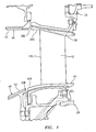
Figure 4 is an expanded view of an interface between a combustor section and a turbine section; -
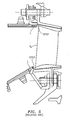
Figure 5 is an expanded view of a RELATED ART combustor section and a portion of a turbine section downstream thereof; and -
Figure 6 is an expanded view of a RELATED ART interface between a combustor section and a turbine section. -
Figure 1 schematically illustrates agas turbine engine 10 which generally includes afan section 12, acompressor section 14, acombustor section 16, aturbine section 18, anaugmentor section 20, and anozzle section 22. Thecompressor section 14,combustor section 16, andturbine section 18 are generally referred to as the core engine. Thegas turbine engine 10 defines a longitudinal axis A which is centrally disposed and extends longitudinally through each section. Thegas turbine engine 10 of the disclosed non-limiting embodiment is a low bypass augmented gas turbine engine having a three-stage fan, a six-stage compressor, an annular combustor, a single stage high-pressure turbine, a two-stage low pressure turbine and convergent/divergent nozzle, however, various gas turbine engines will benefit from the disclosure. - Air compressed in the
compressor section 14 is mixed with fuel, burned in thecombustor section 16 and expanded inturbine section 18. Theturbine section 18, in response to the expansion, drives thecompressor section 14 and thefan section 12. The air compressed in thecompressor section 14 and the fuel mixture expanded in theturbine section 18 may be referred to as the core flow C. Air from thefan section 12 is divided between the core flow C and a bypass or secondary flow B. Core flow C follows a path through thecombustor section 16 and also passes through theaugmentor section 20 where fuel may be selectively injected into the core flow C and burned to impart still more energy to the core flow C and generate additional thrust from thenozzle section 22. - An
outer engine case 24 and aninner structure 26 define a generally annularsecondary bypass duct 28 around a core flow C. It should be understood that various structure within the engine may be defined as theouter engine case 24 and theinner structure 26 to define various secondary flow paths such as the disclosedbypass duct 28. The core engine is arranged generally within thebypass duct 28. Thebypass duct 28 separates airflow sourced from thefan section 12 and/orcompressor section 14 as the secondary flow B between theouter engine case 24 and theinner structure 26. The secondary flow B also generally follows a path parallel to the axis A of theengine 10, passing through thebypass duct 28 along the periphery of theengine 10. - The
turbine section 18 includes alternate rows of static airfoils orvanes 30 radially fixed to theinner structure 26 and rotary airfoils orblades 32 mountable todisks 34 for rotation about the engine axis A. A first row ofvanes 30 is located directly downstream of thecombustor section 16. - Referring to
Figure 2 , the first row ofvanes 30 may be defined by a multiple ofturbine nozzle segments 36 which include an arcuateouter vane platform 38, an arcuateinner vane platform 40 and at least oneturbine vane 42 which extends radially between thevane platform outer vane platform 38 may form an outer portion of theinner structure 26 and the arcuateinner vane platform 40 may form an inner portion of theinner structure 26 to at least partially define an annular core flow path interface from thecombustor section 16 to the turbine section 18 (Figure 1 ). The temperature environment of theturbine section 18 and the substantial aerodynamic and thermal loads are accommodated by the multiple of circumferentially adjoiningnozzle segments 36 which collectively form a full, annular ring about the centerline axis A. - Referring to
Figure 3 , thecombustor section 16 includes anannular combustor 44 which includes an outerliner panel structure 46 and an innerliner panel structure 48. Theannular combustor 44 in the disclosed, non-limiting embodiment utilizes effusion cooling from the secondary flow B to maintain acceptable temperatures immediately upstream of the first row of turbine vanes 30. - The outer
liner panel structure 46 is located adjacent to the arcuateouter vane platform 38 and the innerliner panel structure 48 is located adjacent to the arcuateinner vane platform 40 to provide a smooth flow path interface between thecombustor section 16 and theturbine section 18. Asegment 38S of the arcuateouter vane platform 38 is generally contiguous and follows the contour of the outerliner panel structure 46 and asegment 40S of the arcuateinner vane platform 40 is generally contiguous and follows the contour of the innerliner panel structure 48 to define a smooth flow path therebetween. That is, thesegment 38S and thesegment 40S essentially extend the respectiveliner panel structure segment 38S and thesegment 40S are defined over approximately the first 20% of thevane platforms Figure 4 ). That is, the smooth flow path defined by the combustorliner panel structure respective vane platform - Alternatively, or in addition, a leading
edge 42L of thevane 42 is located downstream of the interface between the combustorliner panel structure respective vane platform edge 42L is set back from the forward most leadingedge respective vane platform 38, 40 (Figure 4 ). In the disclosed, non-limiting embodiment, the leadingedge 42L is set back from the leadingedge vane platforms - With the smooth flow path, cooling for the combustor
liner panel structure effusion holes 50 in the combustorliner panel structure liner panel structure liner panel structure vane platform vane platform turbine vanes 42. The reduced secondary flow effects also reduce the radial movement of hot gases from thecombustor section 16 towards thevane platform - In the related art (
Figure 5 ) an aft end segment of the combustor liner panel L required specific cooling to maintain metal temperatures immediately upstream of a turbine vane leading edge Ve. A step in the flowpath exhausts coolant from the combustor panel upstream of the turbine vane. This flow is exhausted at a lower velocity and total pressure than the core flow and thus a pressure gradient was generated near the turbine vane platform leading edge. - Applicant has determined that the removal or minimization of the aft facing step between the combustor liner panel L and the vane platform Vp reduces or eliminates the bow wave effect that increases the thermal load locally which results in stagnation of hot gas at the trailing edge of the liner panel. The aft facing step and cooling exhaust also impacts the flow through the first turbine vane. The cooling air exiting the aft step slot has a much lower velocity than the mainstream flow creating a gradient. This gradient contributes to flow vorticity at the leading edge of the turbine vane and results in radial mixing that transports hot gases from the core flow towards the turbine vane platform areas (
Figure 6 ; related art) which may generate an increased thermal load. - The disclosure provides a geometry that requires less cooling and improves durability. The overall effect is to reduce cooling flow in the combustor section and turbine section, or to achieve improved durability with constant flow through the reduced heat load on the aft end of the combustor liner panels and first turbine vane platforms.
- Although particular step sequences are shown, described, and claimed, it should be understood that steps may be performed in any order, separated or combined unless otherwise indicated and will still benefit from the present disclosure.
- The foregoing description is exemplary rather than defined by the limitations within. Various non-limiting embodiments are disclosed herein, however, one of ordinary skill in the art would recognize that various modifications and variations in light of the above teachings will fall within the scope of the appended claims. It is therefore to be understood that within the scope of the appended claims, the disclosure may be practiced other than as specifically described. For that reason the appended claims should be studied to determine true scope and content.
Claims (14)
- A gas turbine engine (10) comprising:a combustor section (16) which includes an outer combustor liner panel structure (46) and an inner combustor liner panel structure (48) defined about an axis; anda turbine section (18) downstream of said combustor section (16), said turbine section (18) including an arcuate outer vane platform (38) and an arcuate inner vane platform (40) defined about said axis, said arcuate outer vane platform (38) including a segment (38S) along said axis which follows said outer combustor liner panel structure (46) and said arcuate inner vane platform (40) including a segment (40S) which follows said inner combustor liner panel (48) structure to define a smooth flow path from said combustor section (16) into said turbine section (18).
- The gas turbine engine as recited in claim 1, wherein said segment (38S) of said arcuate outer vane platform (38) and said segment (40S) of said arcuate inner vane platform (40S) extends for approximately 20% of a length of said respective arcuate outer vane platform (38) and said arcuate inner vane platform (40).
- The gas turbine engine as recited in claim 1 or 2, wherein said segment (38S) of said arcuate outer vane platform (38) and said segment (40S) of said arcuate inner vane platform (40) follows a respective contour of said outer combustor liner panel structure (46) and said inner combustor liner panel structure (48).
- The gas turbine engine as recited in claim 1, 2 or 3, wherein said segment (38S) of said arcuate outer vane platform (38) and said segment (40S) of said arcuate inner vane platform (40) follows a respective step-less contour of said outer combustor liner panel structure (46) and said inner combustor liner panel structure (48).
- The gas turbine engine as recited in any preceding claim, further comprising a vane (42) which extends in a radial direction between said arcuate outer vane platform (38) and said arcuate inner vane platform (40), said vane (42) defining a leading edge (42L) which is set back from a forward most edge (38E,40E) of said arcuate outer vane platform (38) and said arcuate inner vane platform (40).
- The gas turbine engine as recited in claim 5, wherein said leading edge (42L) is set back approximately 20% from said forward most edge (38E,40E) of said arcuate outer vane platform (38) and said arcuate inner vane platform (40).
- The gas turbine engine as recited in any preceding claim, wherein said combustor section (16) includes an annular combustor (44) that utilizes effusion cooling.
- The gas turbine engine as recited in claim 7, wherein said annular combustor (44) is at least partially defined by said outer combustor liner panel structure (46) and said inner combustor liner panel structure (48).
- The gas turbine engine as recited in claim 8, wherein said outer combustor liner panel structure (46) and said inner combustor liner panel structure (48) include effusion holes.
- A turbine vane (42) downstream of a combustor section (16) comprising:an arcuate outer vane platform (38) defined about an axis, said arcuate outer vane platform (38) including a segment (38S) of said arcuate outer vane platform (38) along said axis which follows an outer combustor liner panel structure (46); andan arcuate inner vane platform (40) defined about said axis, said arcuate inner vane platform (40) includes a segment (40S) of said arcuate inner vane platform (40) along said axis which follows an inner combustor liner panel structure (48).
- The turbine vane as recited in claim 10, wherein said segment (38S) of said arcuate outer vane platform (38) and said segment (40S) of said arcuate inner vane platform (40) extends for approximately 20% of a length of said respective arcuate outer vane platform (38) and said arcuate inner vane platform (40).
- The turbine vane as recited in claim 10 or 11, wherein said segment (38S) of said arcuate outer vane platform (38) and said segment (40S) of said arcuate inner vane platform (40) follows a respective contour of said outer combustor liner panel structure (46) and said inner combustor liner panel structure (48).
- The turbine vane as recited in any of claims 10 to 12, further comprising a vane (42) which extends in a radial direction between said arcuate outer vane platform (38) and said arcuate inner vane platform (40), said vane (42) defines a leading edge (42L) which is set back from a forward most edge (38E,40E) of said arcuate outer vane platform (38) and said arcuate inner vane platform (40).
- The turbine vane as recited in claim 13, wherein said leading edge (42L) is set back approximately 20% from said forward most edge (38E,40E) of said arcuate outer vane platform (38) and said arcuate inner vane platform (40).
Applications Claiming Priority (1)
| Application Number | Priority Date | Filing Date | Title |
|---|---|---|---|
| US12/549,693 US9650903B2 (en) | 2009-08-28 | 2009-08-28 | Combustor turbine interface for a gas turbine engine |
Publications (2)
| Publication Number | Publication Date |
|---|---|
| EP2290195A2 true EP2290195A2 (en) | 2011-03-02 |
| EP2290195A3 EP2290195A3 (en) | 2013-10-16 |
Family
ID=42955167
Family Applications (1)
| Application Number | Title | Priority Date | Filing Date |
|---|---|---|---|
| EP10251501.2A Withdrawn EP2290195A3 (en) | 2009-08-28 | 2010-08-26 | Combustor turbine interface for a gas turbine engine |
Country Status (2)
| Country | Link |
|---|---|
| US (1) | US9650903B2 (en) |
| EP (1) | EP2290195A3 (en) |
Cited By (1)
| Publication number | Priority date | Publication date | Assignee | Title |
|---|---|---|---|---|
| EP3034798A1 (en) * | 2014-12-18 | 2016-06-22 | Alstom Technology Ltd | Gas turbine vane |
Families Citing this family (2)
| Publication number | Priority date | Publication date | Assignee | Title |
|---|---|---|---|---|
| US8226360B2 (en) * | 2008-10-31 | 2012-07-24 | General Electric Company | Crenelated turbine nozzle |
| FR3084141B1 (en) * | 2018-07-19 | 2021-04-02 | Safran Aircraft Engines | SET FOR A TURBOMACHINE |
Family Cites Families (52)
| Publication number | Priority date | Publication date | Assignee | Title |
|---|---|---|---|---|
| US2055928A (en) * | 1934-10-08 | 1936-09-29 | Russell R Hays | Rotating blade means for aircraft |
| US2918978A (en) * | 1957-02-11 | 1959-12-29 | United Aircraft Corp | Variable contour propeller blades |
| US3302926A (en) * | 1965-12-06 | 1967-02-07 | Gen Electric | Segmented nozzle diaphragm for high temperature turbine |
| FR1496151A (en) * | 1966-06-20 | 1967-09-29 | Giravions Dorand | Diverter flap for fluid jet |
| GB1193587A (en) | 1968-04-09 | 1970-06-03 | Rolls Royce | Nozzle Guide Vanes for Gas Turbine Engines. |
| GB1235545A (en) * | 1968-09-12 | 1971-06-16 | Rolls Royce | Improvements in or relating to blades or vanes for fluid flow machines |
| DE2348304C3 (en) * | 1973-09-26 | 1980-01-24 | Dornier System Gmbh, 7990 Friedrichshafen | Flow body for influencing flowing media |
| DE2453558C3 (en) * | 1974-11-12 | 1979-08-30 | Dornier Gmbh, 7990 Friedrichshafen | Thrust gas deflection vane |
| US4012908A (en) * | 1976-01-30 | 1977-03-22 | Twin Disc, Incorporated | Torque converter having adjustably movable stator vane sections |
| CA1040535A (en) * | 1976-02-09 | 1978-10-17 | Westinghouse Electric Corporation | Variable vane and flowpath support assembly for a gas turbine |
| US4235397A (en) * | 1978-04-29 | 1980-11-25 | British Aerospace | Flow deflector blades |
| US4733538A (en) * | 1978-10-02 | 1988-03-29 | General Electric Company | Combustion selective temperature dilution |
| US4295784A (en) * | 1979-09-26 | 1981-10-20 | United Technologies Corporation | Variable stator |
| US4679400A (en) * | 1983-12-15 | 1987-07-14 | General Electric Company | Variable turbine vane support |
| FR2576974B1 (en) * | 1985-02-06 | 1989-02-03 | Snecma | DEVICE FOR VARIING THE SECTION OF THE NECK OF A TURBINE DISTRIBUTOR |
| US4652208A (en) * | 1985-06-03 | 1987-03-24 | General Electric Company | Actuating lever for variable stator vanes |
| FR2586268B1 (en) * | 1985-08-14 | 1989-06-09 | Snecma | DEVICE FOR VARIATION OF THE PASSAGE SECTION OF A TURBINE DISTRIBUTOR |
| US4768922A (en) * | 1986-09-15 | 1988-09-06 | Avco Corporation | Variable stator and shroud assembly |
| GB2210935B (en) * | 1987-10-10 | 1992-05-27 | Rolls Royce Plc | Variable stator vane assembly |
| US4856962A (en) * | 1988-02-24 | 1989-08-15 | United Technologies Corporation | Variable inlet guide vane |
| CA2070511C (en) * | 1991-07-22 | 2001-08-21 | Steven Milo Toborg | Turbine nozzle support |
| US5207558A (en) * | 1991-10-30 | 1993-05-04 | The United States Of America As Represented By The Secretary Of The Air Force | Thermally actuated vane flow control |
| ES2063636B1 (en) * | 1992-04-23 | 1997-05-01 | Turbo Propulsores Ind | SET OF STATOR BLADES FOR GAS TURBINE ENGINES. |
| FR2714109B1 (en) * | 1993-12-22 | 1996-01-19 | Snecma | Variable camber turbomachine blade. |
| US5628193A (en) * | 1994-09-16 | 1997-05-13 | Alliedsignal Inc. | Combustor-to-turbine transition assembly |
| GB9723762D0 (en) * | 1997-11-12 | 1998-01-07 | Rolls Royce Plc | A method of coating a component |
| US6290459B1 (en) * | 1999-11-01 | 2001-09-18 | General Electric Company | Stationary flowpath components for gas turbine engines |
| GB2380236B (en) * | 2001-09-29 | 2005-01-19 | Rolls Royce Plc | A wall structure for a combustion chamber of a gas turbine engine |
| US6495207B1 (en) * | 2001-12-21 | 2002-12-17 | Pratt & Whitney Canada Corp. | Method of manufacturing a composite wall |
| US6887035B2 (en) * | 2002-10-23 | 2005-05-03 | General Electric Company | Tribologically improved design for variable stator vanes |
| US6871488B2 (en) * | 2002-12-17 | 2005-03-29 | Pratt & Whitney Canada Corp. | Natural gas fuel nozzle for gas turbine engine |
| GB2396687A (en) * | 2002-12-23 | 2004-06-30 | Rolls Royce Plc | Helmholtz resonator for combustion chamber use |
| US7025564B2 (en) * | 2003-01-27 | 2006-04-11 | The United States Of America As Represented By The Secretary Of The Army | Devices and methods for reducing or eliminating the gap between a stay vane and its corresponding wicket gate as used in turbines |
| DE602004027993D1 (en) * | 2003-02-24 | 2010-08-19 | Pratt & Whitney Canada | BUILT-IN COOLING SYSTEM FOR A CIRCULAR MOTOR |
| FR2853000B1 (en) * | 2003-03-25 | 2007-05-04 | Snecma Moteurs | COOLING AIR INJECTION DEVICE IN A TURBINE ROTOR |
| DE10313729B4 (en) * | 2003-03-27 | 2007-11-29 | Airbus Deutschland Gmbh | Air outlet valve for an aircraft |
| US7370467B2 (en) * | 2003-07-29 | 2008-05-13 | Pratt & Whitney Canada Corp. | Turbofan case and method of making |
| US7114920B2 (en) * | 2004-06-25 | 2006-10-03 | Pratt & Whitney Canada Corp. | Shroud and vane segments having edge notches |
| US7238003B2 (en) * | 2004-08-24 | 2007-07-03 | Pratt & Whitney Canada Corp. | Vane attachment arrangement |
| US7172388B2 (en) * | 2004-08-24 | 2007-02-06 | Pratt & Whitney Canada Corp. | Multi-point seal |
| US7260936B2 (en) * | 2004-08-27 | 2007-08-28 | Pratt & Whitney Canada Corp. | Combustor having means for directing air into the combustion chamber in a spiral pattern |
| US7229247B2 (en) * | 2004-08-27 | 2007-06-12 | Pratt & Whitney Canada Corp. | Duct with integrated baffle |
| US7229249B2 (en) * | 2004-08-27 | 2007-06-12 | Pratt & Whitney Canada Corp. | Lightweight annular interturbine duct |
| US7527469B2 (en) * | 2004-12-10 | 2009-05-05 | Siemens Energy, Inc. | Transition-to-turbine seal apparatus and kit for transition/turbine junction of a gas turbine engine |
| US7506512B2 (en) * | 2005-06-07 | 2009-03-24 | Honeywell International Inc. | Advanced effusion cooling schemes for combustor domes |
| EP1741877A1 (en) | 2005-07-04 | 2007-01-10 | Siemens Aktiengesellschaft | Heat shield and stator vane for a gas turbine |
| US7360988B2 (en) * | 2005-12-08 | 2008-04-22 | General Electric Company | Methods and apparatus for assembling turbine engines |
| US7934382B2 (en) * | 2005-12-22 | 2011-05-03 | United Technologies Corporation | Combustor turbine interface |
| US8038389B2 (en) * | 2006-01-04 | 2011-10-18 | General Electric Company | Method and apparatus for assembling turbine nozzle assembly |
| EP1985806A1 (en) | 2007-04-27 | 2008-10-29 | Siemens Aktiengesellschaft | Platform cooling of a turbine vane |
| FR2921463B1 (en) * | 2007-09-26 | 2013-12-06 | Snecma | COMBUSTION CHAMBER OF A TURBOMACHINE |
| US8266914B2 (en) * | 2008-10-22 | 2012-09-18 | Pratt & Whitney Canada Corp. | Heat shield sealing for gas turbine engine combustor |
-
2009
- 2009-08-28 US US12/549,693 patent/US9650903B2/en active Active
-
2010
- 2010-08-26 EP EP10251501.2A patent/EP2290195A3/en not_active Withdrawn
Non-Patent Citations (1)
| Title |
|---|
| None |
Cited By (3)
| Publication number | Priority date | Publication date | Assignee | Title |
|---|---|---|---|---|
| EP3034798A1 (en) * | 2014-12-18 | 2016-06-22 | Alstom Technology Ltd | Gas turbine vane |
| CN105715309A (en) * | 2014-12-18 | 2016-06-29 | 通用电器技术有限公司 | Gas turbine vane |
| US10221709B2 (en) | 2014-12-18 | 2019-03-05 | Ansaldo Energia Switzerland AG | Gas turbine vane |
Also Published As
| Publication number | Publication date |
|---|---|
| US9650903B2 (en) | 2017-05-16 |
| EP2290195A3 (en) | 2013-10-16 |
| US20110052381A1 (en) | 2011-03-03 |
Similar Documents
| Publication | Publication Date | Title |
|---|---|---|
| US10704468B2 (en) | Method and apparatus for handling pre-diffuser airflow for cooling high pressure turbine components | |
| EP2075437B1 (en) | Multi-source gas turbine cooling | |
| US8973374B2 (en) | Blades in a turbine section of a gas turbine engine | |
| US9920633B2 (en) | Compound fillet for a gas turbine airfoil | |
| US10125722B2 (en) | Turbine engine with a turbo-compressor | |
| US10337401B2 (en) | Turbine engine with a turbo-compressor | |
| JP2006105138A (en) | Method and apparatus for assembling a gas turbine engine | |
| US10100731B2 (en) | Turbine engine with a turbo-compressor | |
| US20160237895A1 (en) | Turbine engine with a turbo-compressor | |
| US9650903B2 (en) | Combustor turbine interface for a gas turbine engine | |
| US20160312654A1 (en) | Turbine airfoil cooling | |
| WO2013137960A1 (en) | Turbine blades in a gas turbine engine |
Legal Events
| Date | Code | Title | Description |
|---|---|---|---|
| PUAI | Public reference made under article 153(3) epc to a published international application that has entered the european phase |
Free format text: ORIGINAL CODE: 0009012 |
|
| AK | Designated contracting states |
Kind code of ref document: A2 Designated state(s): AL AT BE BG CH CY CZ DE DK EE ES FI FR GB GR HR HU IE IS IT LI LT LU LV MC MK MT NL NO PL PT RO SE SI SK SM TR |
|
| AX | Request for extension of the european patent |
Extension state: BA ME RS |
|
| PUAL | Search report despatched |
Free format text: ORIGINAL CODE: 0009013 |
|
| AK | Designated contracting states |
Kind code of ref document: A3 Designated state(s): AL AT BE BG CH CY CZ DE DK EE ES FI FR GB GR HR HU IE IS IT LI LT LU LV MC MK MT NL NO PL PT RO SE SI SK SM TR |
|
| AX | Request for extension of the european patent |
Extension state: BA ME RS |
|
| RIC1 | Information provided on ipc code assigned before grant |
Ipc: F01D 9/02 20060101AFI20130910BHEP Ipc: F01D 9/04 20060101ALI20130910BHEP |
|
| 17P | Request for examination filed |
Effective date: 20140331 |
|
| RBV | Designated contracting states (corrected) |
Designated state(s): AL AT BE BG CH CY CZ DE DK EE ES FI FR GB GR HR HU IE IS IT LI LT LU LV MC MK MT NL NO PL PT RO SE SI SK SM TR |
|
| RAP1 | Party data changed (applicant data changed or rights of an application transferred) |
Owner name: UNITED TECHNOLOGIES CORPORATION |
|
| 17Q | First examination report despatched |
Effective date: 20161006 |
|
| STAA | Information on the status of an ep patent application or granted ep patent |
Free format text: STATUS: EXAMINATION IS IN PROGRESS |
|
| STAA | Information on the status of an ep patent application or granted ep patent |
Free format text: STATUS: THE APPLICATION HAS BEEN WITHDRAWN |
|
| 18W | Application withdrawn |
Effective date: 20180713 |