EP2289628A1 - Magnetic separator with eddy current, with optimised trajectory and interaction zone of the particles - Google Patents
Magnetic separator with eddy current, with optimised trajectory and interaction zone of the particles Download PDFInfo
- Publication number
- EP2289628A1 EP2289628A1 EP09168815A EP09168815A EP2289628A1 EP 2289628 A1 EP2289628 A1 EP 2289628A1 EP 09168815 A EP09168815 A EP 09168815A EP 09168815 A EP09168815 A EP 09168815A EP 2289628 A1 EP2289628 A1 EP 2289628A1
- Authority
- EP
- European Patent Office
- Prior art keywords
- magnetic
- wheel
- belt
- particles
- wall
- Prior art date
- Legal status (The legal status is an assumption and is not a legal conclusion. Google has not performed a legal analysis and makes no representation as to the accuracy of the status listed.)
- Granted
Links
- 239000002245 particle Substances 0.000 title claims abstract description 64
- 230000003993 interaction Effects 0.000 title claims abstract description 8
- 239000006148 magnetic separator Substances 0.000 title claims description 30
- 230000005291 magnetic effect Effects 0.000 claims abstract description 188
- 238000000926 separation method Methods 0.000 claims abstract description 19
- CWYNVVGOOAEACU-UHFFFAOYSA-N Fe2+ Chemical compound [Fe+2] CWYNVVGOOAEACU-UHFFFAOYSA-N 0.000 claims abstract description 12
- 239000002184 metal Substances 0.000 claims description 15
- 229910052751 metal Inorganic materials 0.000 claims description 15
- 239000000463 material Substances 0.000 claims description 13
- -1 ferrous metals Chemical class 0.000 claims description 11
- 230000005294 ferromagnetic effect Effects 0.000 claims description 4
- 239000013528 metallic particle Substances 0.000 claims description 2
- 239000002923 metal particle Substances 0.000 abstract description 5
- 239000013590 bulk material Substances 0.000 description 8
- 230000008859 change Effects 0.000 description 7
- 238000010276 construction Methods 0.000 description 6
- 239000006249 magnetic particle Substances 0.000 description 4
- 238000011084 recovery Methods 0.000 description 4
- 238000011144 upstream manufacturing Methods 0.000 description 4
- 230000008878 coupling Effects 0.000 description 3
- 238000010168 coupling process Methods 0.000 description 3
- 238000005859 coupling reaction Methods 0.000 description 3
- 230000000694 effects Effects 0.000 description 3
- 230000005484 gravity Effects 0.000 description 3
- 238000004804 winding Methods 0.000 description 3
- 238000009825 accumulation Methods 0.000 description 2
- 239000004020 conductor Substances 0.000 description 2
- 238000009826 distribution Methods 0.000 description 2
- 238000009434 installation Methods 0.000 description 2
- 238000007885 magnetic separation Methods 0.000 description 2
- 238000012423 maintenance Methods 0.000 description 2
- 239000007769 metal material Substances 0.000 description 2
- 238000005299 abrasion Methods 0.000 description 1
- 230000005540 biological transmission Effects 0.000 description 1
- 239000012141 concentrate Substances 0.000 description 1
- 238000005553 drilling Methods 0.000 description 1
- 239000010419 fine particle Substances 0.000 description 1
- 230000001939 inductive effect Effects 0.000 description 1
- 238000004519 manufacturing process Methods 0.000 description 1
- 238000005259 measurement Methods 0.000 description 1
- 230000009347 mechanical transmission Effects 0.000 description 1
- 238000000034 method Methods 0.000 description 1
- 230000005298 paramagnetic effect Effects 0.000 description 1
- 239000002907 paramagnetic material Substances 0.000 description 1
- 230000035699 permeability Effects 0.000 description 1
- 230000001737 promoting effect Effects 0.000 description 1
- 238000004064 recycling Methods 0.000 description 1
- 230000009467 reduction Effects 0.000 description 1
- 239000007787 solid Substances 0.000 description 1
- 230000007704 transition Effects 0.000 description 1
Images


Classifications
-
- B—PERFORMING OPERATIONS; TRANSPORTING
- B03—SEPARATION OF SOLID MATERIALS USING LIQUIDS OR USING PNEUMATIC TABLES OR JIGS; MAGNETIC OR ELECTROSTATIC SEPARATION OF SOLID MATERIALS FROM SOLID MATERIALS OR FLUIDS; SEPARATION BY HIGH-VOLTAGE ELECTRIC FIELDS
- B03C—MAGNETIC OR ELECTROSTATIC SEPARATION OF SOLID MATERIALS FROM SOLID MATERIALS OR FLUIDS; SEPARATION BY HIGH-VOLTAGE ELECTRIC FIELDS
- B03C1/00—Magnetic separation
- B03C1/02—Magnetic separation acting directly on the substance being separated
- B03C1/23—Magnetic separation acting directly on the substance being separated with material carried by oscillating fields; with material carried by travelling fields, e.g. generated by stationary magnetic coils; Eddy-current separators, e.g. sliding ramp
- B03C1/24—Magnetic separation acting directly on the substance being separated with material carried by oscillating fields; with material carried by travelling fields, e.g. generated by stationary magnetic coils; Eddy-current separators, e.g. sliding ramp with material carried by travelling fields
- B03C1/247—Magnetic separation acting directly on the substance being separated with material carried by oscillating fields; with material carried by travelling fields, e.g. generated by stationary magnetic coils; Eddy-current separators, e.g. sliding ramp with material carried by travelling fields obtained by a rotating magnetic drum
-
- B—PERFORMING OPERATIONS; TRANSPORTING
- B03—SEPARATION OF SOLID MATERIALS USING LIQUIDS OR USING PNEUMATIC TABLES OR JIGS; MAGNETIC OR ELECTROSTATIC SEPARATION OF SOLID MATERIALS FROM SOLID MATERIALS OR FLUIDS; SEPARATION BY HIGH-VOLTAGE ELECTRIC FIELDS
- B03C—MAGNETIC OR ELECTROSTATIC SEPARATION OF SOLID MATERIALS FROM SOLID MATERIALS OR FLUIDS; SEPARATION BY HIGH-VOLTAGE ELECTRIC FIELDS
- B03C1/00—Magnetic separation
- B03C1/02—Magnetic separation acting directly on the substance being separated
- B03C1/025—High gradient magnetic separators
- B03C1/031—Component parts; Auxiliary operations
- B03C1/033—Component parts; Auxiliary operations characterised by the magnetic circuit
- B03C1/0332—Component parts; Auxiliary operations characterised by the magnetic circuit using permanent magnets
-
- B—PERFORMING OPERATIONS; TRANSPORTING
- B03—SEPARATION OF SOLID MATERIALS USING LIQUIDS OR USING PNEUMATIC TABLES OR JIGS; MAGNETIC OR ELECTROSTATIC SEPARATION OF SOLID MATERIALS FROM SOLID MATERIALS OR FLUIDS; SEPARATION BY HIGH-VOLTAGE ELECTRIC FIELDS
- B03C—MAGNETIC OR ELECTROSTATIC SEPARATION OF SOLID MATERIALS FROM SOLID MATERIALS OR FLUIDS; SEPARATION BY HIGH-VOLTAGE ELECTRIC FIELDS
- B03C1/00—Magnetic separation
- B03C1/02—Magnetic separation acting directly on the substance being separated
- B03C1/16—Magnetic separation acting directly on the substance being separated with material carriers in the form of belts
- B03C1/18—Magnetic separation acting directly on the substance being separated with material carriers in the form of belts with magnets moving during operation
-
- B—PERFORMING OPERATIONS; TRANSPORTING
- B03—SEPARATION OF SOLID MATERIALS USING LIQUIDS OR USING PNEUMATIC TABLES OR JIGS; MAGNETIC OR ELECTROSTATIC SEPARATION OF SOLID MATERIALS FROM SOLID MATERIALS OR FLUIDS; SEPARATION BY HIGH-VOLTAGE ELECTRIC FIELDS
- B03C—MAGNETIC OR ELECTROSTATIC SEPARATION OF SOLID MATERIALS FROM SOLID MATERIALS OR FLUIDS; SEPARATION BY HIGH-VOLTAGE ELECTRIC FIELDS
- B03C2201/00—Details of magnetic or electrostatic separation
- B03C2201/20—Magnetic separation whereby the particles to be separated are in solid form
Definitions
- the invention relates to a magnetic separator for particles and pieces of non-ferrous metals. More particularly to a magnetic separator using the principle of eddy currents.
- an eddy current magnetic separator which typically comprises a magnetic wheel disposed under a solid bulk material conveyor belt or belt, at a location corresponding to a change of direction of the web, typically at the transition from horizontal to vertical.
- the magnetic wheel or polar wheel typically comprises a series of permanent magnets or sometimes electromagnets which are arranged radially and successively along the circumference of the wheel.
- the magnets are oriented so that the magnetic fields generated successively along the circumference are oriented radially and direction successively reversed. In this way a particle of non-ferrous metal, that is to say a paramagnetic material, located near the magnetic wheel will be subjected to a variable magnetic field.
- This variable magnetic field will generate electromotive forces that will induce currents in the conductive material of the particles. These currents will create a magnetic field which opposes the magnetic field generated by the magnetic wheel which is the cause of the variation of the field outside. As a result, a repulsive force is applied to the particles which cause them to peel off the conveyor belt, which allows separation of these particles.
- the document EP 0 439 983 A discloses a magnetic separator comprising a closed belt guided by three wheels.
- a first wheel provides a change of direction to 180 ° of the belt
- a second wheel operates a change of direction of the order of 40 ° -45 °
- a third wheel operates a change of direction of the order of 135-140 ° by returning the belt to the first wheel.
- a magnetic wheel is housed in the second wheel.
- the magnetic wheel rotates in the same direction as the guide wheel but at a substantially higher speed. It generates a variable magnetic field at the outer surface of the belt on a sector of the second wheel corresponding to the contact area of the belt with the wheel in question.
- This construction has various disadvantages.
- the interaction zone between the variable magnetic field generated by the magnetic wheel is limited to the aforementioned sector, which has the effect of limiting the maximum speed of movement of the belt.
- Some particularly fine particles or agglomerated with other non-metallic sometimes require the application of the variable magnetic field for a longer duration than other particles in order to be separated.
- the document EP 0 388 626 A 1 discloses a similar device where the belt is deflected by about 90 ° at the point of separation.
- a box is provided with a curved wall serving as support by sliding the belt.
- a magnetic wheel is housed in the box under the wall so as to generate a variable magnetic field particles carried by the belt and approaching the wheel magnetic.
- This document provides a wall of weakly conductive material so as to reduce the decrease of the magnetic field with the distance of the magnetic wheel in a radial direction.
- This document further provides the presence of a material element having good magnetic properties and poor conductivity. This element is disposed facing the outer surface of the curved wall on a direction corresponding to a radius of the magnetic wheel inclined at 45 °.
- This element The role of this element is to concentrate the magnetic field lines and thus the repulsion forces to a smaller magnetic wheel sector. This measurement is intended to increase the repulsion forces in a smaller interaction zone and thereby to better control the expulsion trajectories.
- This device is however not well suited to the separation of certain agglomerated particles with other non-metallic particles. In addition, the speed of travel of the belt is quite limited.
- the document JP 57 117353 A discloses a magnetic separator with a chute feeding the bulk material onto the top of a conveyor belt disposed substantially vertically.
- the upper guide wheel incorporates a magnetic wheel having the effect of generating repulsive forces for separating non-magnetic metal particles to the left of the magnetic wheel.
- a second magnetic wheel is arranged facing the outer surface of the conveyor belt. This second magnetic wheel rotates in a reverse direction of rotation to that of the first magnetic wheel.
- a rotating wheel surrounds the second magnetic wheel. It rotates in a direction such that its outer surface near the conveyor belt moves parallel to said belt promoting the flow of magnetic and inert materials to the right. Its role is to protect the second magnetic wheel by preventing the accumulation of magnetic particles on the circumference of the latter. In case of intrusion of particles of any kind whatsoever between the second magnetic wheel and the wheel surrounding it, the fact that these two wheels rotate in opposite directions will cause abrasion damage to the wheels, which will lead to Difficulties of maintenance and stop of the installation.
- the document US 5,080,234 illustrates a separation system involving two magnetic wheels interconnected by a toothed belt transmission ensuring a synchronization such that the magnetic poles of the wheels vis-à-vis remain opposed.
- the second magnetic wheel is disposed above the outer surface of the conveyor belt.
- it does not provide any protection so that the magnetic particles can be attracted to it and accumulate there which can lead to problems of reduction of the magnetic field produced and also, in more extreme cases, obstruction of the passage of the magnetic field. the bulk material in the air gap of the two wheels.
- the object of this invention is to provide a magnetic separator for better separation of particles and / or non-magnetic metal pieces, especially when these particles are agglomerated with other particles or pieces of other nature.
- the invention consists of a magnetic separator of particles and / or pieces of non-ferrous metals comprising: a wall forming a convex and rounded outer surface, said surface being a bearing and sliding surface of a first particle conveyor belt; and / or pieces comprising particles and / or pieces of non-ferrous metals to be separated; a first magnetic wheel disposed facing the inner surface of the wall, said wheel having a circumference and an axis of rotation, said wheel generating, in rotation, variable magnetic fields in the particles and pieces of non-ferrous metals, these variable magnetic fields inducing eddy currents and interaction forces with the magnetic fields generated by said route leading to eject particles and / or pieces of said belt for separation; wherein the wall is such that it circumvents the first magnetic wheel about one quarter of the circumference of said wheel at an approximately constant distance.
- This configuration of the wall provides an optimized working area over a sector of about 90 ° and hence an increased separation rate.
- the distance between the circumference of the first magnetic wheel and the inner surface of the wall is less than or equal to 10%, preferably 5%, of the outer diameter of said wheel on approximately a quarter of its diameter. circumference.
- the wall is intended to guide the first conveyor belt from a generally horizontal direction to a generally vertical direction.
- the wall describes a quarter circle approximately centered on the axis of rotation of the first magnetic wheel.
- the separator comprises a box to which the wall and the first magnetic wheel are fixed.
- the separator comprises means for guiding the belt downstream of the wall to a section where the belt has its outer surface generally facing downwards, and means, preferably of the magnet type. permanent, generating a magnetic field in proximity and along said belt section so as to be able to maintain ferromagnetic particles on said belt section in order to be able to separate them from particles and / or inert pieces, said means being preferentially disposed to inside the box specially designed for this purpose.
- the means in question generate a constant magnetic field near and along the inner face of the belt along the aforementioned section.
- These means may be arranged close to the inner face of the belt, in particular outside the box, for example on an independent frame.
- These means may comprise windings or coils and / or permanent magnets.
- the separator comprises a movable element with respect to the first magnetic wheel and comprising at least one magnetic field source directed towards the magnetic wheel, the mobile element acting as a magnetic brake when brings it closer to the circumference of said wheel.
- the first magnetic wheel comprises a plurality of magnetic field sources distributed along the circumference so as to generate a variable magnetic field for a fixed observer near said wheel when it is rotating
- the separator comprises a movable element relative to said wheel and comprising at least two magnetic field sources distributed along the circumference of said wheel, the magnetic field sources generating magnetic fields directed towards the circumference of said wheel, the movable member acting as magnetic brake for said wheel when brought closer to the circumference of said wheel.
- the magnetic field sources of the first magnetic wheel and / or the magnetic brake consist of permanent magnets or electromagnets.
- the separator comprises a second magnetic wheel disposed facing the outer surface of the wall and intended to rotate in a direction opposite to that of the first magnetic wheel, the rotating magnetic field of the second wheel acting on particles and / or pieces of non-ferrous metals and influencing the ejection path of these particles and pieces.
- the second magnetic wheel is rotated by the first wheel only by interaction of the magnetic fields of the respective wheels.
- a second closed belt is arranged around the second magnetic wheel and around guide means arranged in front of the second magnetic wheel with respect to the direction of advance of the first belt at the beginning of the wall so as to form a section of the second belt facing the outer surface of the wall.
- a wheel is disposed between the second belt and the second magnetic wheel so as to allow a rotation speed of the second magnetic wheel different from the speed of the second belt.
- the portion of the second belt facing the outer surface of the wall is generally parallel to the direction of movement of the first belt at the beginning of the wall.
- the second wheel is arranged so that its axis of rotation is located in front of a plane passing through the axis of rotation of the first magnetic wheel and the beginning of the profile. quarter circle of the wall, and that with respect to the direction of advance of the first belt at the beginning of the wall.
- the assembly formed by the second belt, the second magnetic wheel and the guide means of said belt is movable so as to be able to finely adjust the ejection trajectory of the particles and pieces of non-ferrous metals.
- a main belt or conveyor belt 2 is intended to convey crushed bulk material or at least consist of pieces or particles of different kinds which it is necessary to sort.
- the belt is of the closed type rotating around several wheels or guide rollers. It is guided by a substantially horizontal sliding surface 14, a support roller 12, a rounded slideway 19 describing a change of direction of the order of 90 °, a first return roller 6, a second return roller 8 and a driving roller 10.
- the belt is driven counterclockwise, i.e. in a direction from the driving roller 10 to the rounded slide 19.
- the traveling speed is typically of the order of 1 to 1.5 m / sec.
- the material to be sorted is poured onto the belt 2 on its horizontal part supported by the slide 14.
- the material consists of non-ferrous metal particles or pieces 16 represented by small squares and particles or pieces of other materials 18, typically nonmetallic material and inert and therefore completely insensitive to magnetic fields. These particles or pieces of other materials are represented by small circles.
- the belt is supported by a wall slide 19 comprising a straight section 20 essentially aligned with the slide 14, a rounded section 13 substantially in a quarter circle and a section 21 substantially vertical and perpendicular to the section 20.
- the slide 19 is part of a box 4 enclosing a magnetic wheel 22 disposed near the inner surface of the rounded section 13 of the slide 19.
- the rounded portion 13 describes a quarter circle centered on the axis 15 and the wheel Magnetic is also centered on this axis.
- the distance between the outer surface of the magnetic wheel and the inner surface of the radially-measured wall 13 is substantially constant.
- the magnetic wheel is equipped with a series of permanent magnets.
- the magnets are arranged to present their south and north poles successively towards the circumference of the wheel so as to generate a variable magnetic field for an observer located near the circumference of the wheel when it rotates. Only four permanent magnets are shown, each being shifted by 90 ° compared to the previous one, for simplicity of presentation. Indeed, in practice it is desirable to have more permanent magnets in order to increase the inversion frequency of the magnetic field generated for a rotation speed of the given wheel. In addition, only the north and south poles, respectively, directed towards the circumference of the wheel are illustrated in the figure, also for reasons of simplicity of presentation.
- the rotation of the wheel is in a direction such that its outer surface near the wall 13 moves in the same direction as the belt 2.
- the variable magnetic field will thus generate electromotive forces in the non-magnetic particles that will induce currents that will themselves give rise to magnetic fields opposing the variable magnetic field of the wheel magnetic.
- the direction of rotation of the magnetic wheel is such that the variable magnetic field it generates moves forward with respect to the direction of travel of the strip upstream of the wall 13, and ejects the particles and pieces along a path generally parabolic to a tank 36 for recovering nonferrous metallic materials. As a reminder, these particles and pieces are represented by small squares in the figure.
- a scraper 17 is provided at the level of the belt strand between the first and second return rollers 6 and 8. It serves to loosen the residues that would remain stuck to the belt after it has made a change of direction such that its surface outside is directed at least partially downwards.
- the recovery tank 38 may be provided sufficiently large and positioned to recover these residues. Alternatively, a specific recovery tank (not shown) can be provided.
- the position of the magnetic wheel 22 can be adjusted relative to the casing 4 and hence the wall 13.
- This adjustment possibility is illustrated by the arrows at the axis of rotation 15 of the wheel. It allows a precise adjustment of the distance between the circumference of the wheel and the inner surface of the wall 13. Indeed, the wall 13 is a wear part, it may be necessary to replace it.
- An adjustment of the position of the magnetic wheel may thus be useful in order to compensate for any manufacturing tolerances of the wall 13 while maintaining a minimum radial distance between the circumference of the wheel and the inner surface of the wall. This distance is of the order of a few percent of the diameter of the wheel, generally less than 10%, preferably less than 5% of the diameter.
- a magnetic brake 24 is provided in the casing 4. It consists of an elongated element 26 having a curvature similar to that of the circumference of the magnetic wheel 22.
- This element 26 comprises several permanent magnets arranged successively along the element so as to present each one of its poles towards the circumference of the magnetic wheel 22, these poles directed towards the circumference being alternately of the north-south or south-north type so that each cooperates with an opposite pole of the magnetic wheel when the magnetic brake 24 is moved radially towards the magnetic wheel. It follows that the respective magnets of the magnetic wheel moving in front of the magnets of the magnetic brake will be attracted by those having an opposite pole and repulsed by those having an identical pole. When the brake of the magnetic wheel is approached, the respective poles at the circumference of the magnetic wheel will each be repelled by an identical pole of the brake or attracted by an opposite pole.
- the magnetic brake described above is applicable to any magnetic magnetic separator wheel.
- a second magnetic wheel 33 is provided approximately above the main magnetic wheel 22. It is housed in a wheel 32 serving as a drum or guide roller of a second belt 28.
- This second belt 28 is of the closed type and constitutes a surface protecting the magnetic wheel 33 and guiding the ejection area of the particles and pieces.
- the belt 28 is guided by a wheel 30 disposed at the front of the wheel 32 with respect to the running direction of the conveyor belt 2 just before the wall 13.
- wheel 32 serving as a drum or guide roller could be replaced by a fixed box with a slide for the belt, similar to the main box 4.
- the second magnetic wheel 33 is arranged so that its axis of rotation is slightly offset forwardly relative to a plane passing through the axis of rotation of the main magnetic wheel 15 and the front edge of the rounded wall 13.
- This plane corresponds to a vertical plane in the case of the figure but it should be noted that this plane could, for example, be inclined to the right if the cross section of the belt 2 upstream of the separation zone was inclined towards the high in the direction of scrolling.
- Such a configuration is quite possible as long as the angle of inclination remains reasonable in order to be able to convey the ground or bulk material with the conveyor belt.
- the assembly constituted by the second magnetic wheel 33, its drum 32, its deflection wheel 30 and the belt 28 can be moved for adjustment purposes in a longitudinal direction, that is to say a horizontal direction in the case of the figure.
- This movement is illustrated by the double arrow on the axis 34.
- the whole in The question may also be adjusted by a slight inclination with respect to an axis substantially corresponding to the axis of rotation of the drum 32.
- This movement is illustrated by the double curved arrow on the left of the figure.
- the second magnetic wheel rotates in the opposite direction to the main magnetic wheel so that the magnetic field it produces in the ejection zone moves forward with respect to the running direction of the conveyor belt 2. upstream of the separation zone.
- the variable magnetic field generated by the second magnetic wheel 33 adds to the variable magnetic field generated by the main magnetic wheel. This results in an increase in the electromotive forces and currents induced in the non-magnetic metal particles and therefore the forces subjected to the larger particles.
- the sum of the forces exerted by the two magnetic wheels on the particles is generally directed forward, which ensures a more frank ejection from the quarter-circle working area.
- the offset of the additional magnetic wheel towards the front promotes the take-off of the belt particles capable of being ejected from their arrival at the beginning of the working area, that is to say near the junction between the rounded wall 13 and the upstream right wall or slide 20.
- the effect of the additional wheel is still small, which prevents the particles from being subjected to excessive downward forces which would counteract those exerted by the main wheel.
- the particles once ejected from the beginning of the working area approach, by the beginning of their trajectories, the area of influence of the additional wheel to be then accelerated by the forces exerted by the additional wheel.
- the belt 28 is a wall adapted to rebound itself on certain particles whose ejection paths are such that they meet the belt 28.
- this belt prevents the accumulation on the circumference of the second wheel magnetic wheel 33 of certain magnetic particles that would still be present in the flow of material carried by the conveyor belt 2. Indeed, the belt 28 assures a takeoff of particles potentially attracted by the magnets of the wheel 28.
- the second magnetic wheel is magnetically driven by the main wheel without the presence of mechanical transmission means between the two.
- Wheel main is rotated by an electric motor (not shown) and the magnetic coupling between the respective poles of the two wheels which are vis-à-vis ensures a drive of the additional magnetic wheel 33.
- the torque to to transmit is rather weak considering that this wheel turns freely without causing other elements.
- a slip has a link at the magnetic coupling. After a certain time, the eventual slip will cancel out so that the additional wheel 33 rotates at a circumferential speed close to that of the main wheel 22.
- the pitch or the distance between the permanent magnets at the circumference of the additional wheel 33 is equal or at least close to the pitch of the main wheel to ensure a satisfactory coupling.
- the additional wheel 33 is identical to the main wheel 22. It may, however, be of difference size while observing a pitch of magnet distributions close to that of the main wheel.
- the second closed belt device disposed opposite the separation zone, the second belt surrounding an additional magnetic wheel is applicable to any magnetic separation unit comprising a magnetic wheel disposed under a conveyor belt of crushed or loose material.
- This device can be applied to a magnetic separation unit without the quarter-circle slide for the conveyor belt, such as a unit where the conveyor belt is deflected by a roller including a magnetic wheel.
- main magnetic wheel 22 as well as the additional magnetic wheel 33 can be constructed differently than with permanent magnets. Indeed, it is quite possible to provide electromagnets powered electrically to generate a magnetic field of power and distribution comparable to that generated by permanent magnets. Such a construction is, however, more complex in particular because of the need to provide rotating electrical contacts and windings at the wheel and a corresponding connection.
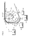
- the figure 2 illustrates a magnetic separator similar to that of the figure 1 with the difference that it has two additional separation functions.
- the box 104 differs from the box 4 of the figure 1 in this it comprises a rounded bottom wall 107 extending along the return portion of the belt.
- This wall is equipped with a series of permanent magnets 105 which are dimensioned and arranged to generate a magnetic field at the belt section vis-à-vis the magnets.
- the first additional separation function concerns the ferrous particles that would have escaped the prior separation by means of a permanent magnet conventionally arranged above the strip. It is therefore essentially small particles that are more difficult to separate due to the low mass / area ratio. These particles are represented by the triangles 142. These particles, due to their high magnetic permeability, are insensitive to the variable magnetic fields generated by the rotation of the wheel 22. They are therefore driven by the belt until they reach the recovery tank 38. particles and inert pieces 18.
- the ferromagnetic particles 142 are then pressed against the band by the fixed magnetic fields emitted by the permanent magnets 105 and then recovered to a third tray 140 by gravity as soon as they are no longer subject to the magnetic field
- the second additional function of separation concerns inert plugging particles 118 which are of a nature quite similar to inert particles 18 but which have the particularity of being sticky and, therefore, have the drawback of not falling into the main recovery tank 38 inert elements.
- a scraper 117 is provided downstream of the permanent magnets 105 so as to loosen these inert particles from the band and recover them in a specific tank 138, once the particles and non-ferrous metal pieces, inert and ferrous separated in the respective trays 36, 38 and 140.
- the figure 3 illustrates a magnetic separator similar to that of the figure 2 where, however, the first additional function, namely that of separating the ferrous particles that would have escaped the prior separation by means of a permanent magnet conventionally disposed above the band, is provided by an alternative configuration.
- the lower part of the box 1104 enclosing the magnetic wheel 22 is adapted to allow the placement of permanent magnets 1105 along the inner face of the strip on the vertical or near vertical section after the change of direction operated around the wheel 22.
- the particles 142 are pressed against the band by the fixed magnetic fields emitted by the permanent magnets 1105 and are driven by the band until the cessation of the magnetic field. They are recovered to a third tank 140 by gravity as soon as they are no longer subject to the magnetic field of the magnets 105.
- the generation of the constant magnetic field by the permanent magnets 105 and 1105 in the examples of the figures 2 and 3 can be provided, alternately or in addition, by windings or coils traversed by a current.
Abstract
Description
L'invention a trait à un séparateur magnétique pour particules et morceaux de métaux non ferreux. Plus particulièrement à un séparateur magnétique utilisant le principe des courants de Foucault.The invention relates to a magnetic separator for particles and pieces of non-ferrous metals. More particularly to a magnetic separator using the principle of eddy currents.
Notamment dans le recyclage industriel, il est souvent nécessaire de pouvoir trier des matériaux broyés en séparant les particules ou morceaux métalliques présents dans la masse en vrac. Typiquement ce genre de matériau en vrac est manipulé et transporté sur des convoyeurs à courroie ou bande ou sur des alimentateurs vibrants. Les particules ou morceaux métalliques ferreux peuvent être assez aisément séparés en appliquant un champ magnétique fixe à proximité de la matière en vrac, typiquement en plaçant un aimant permanent directement au dessus du convoyeur à bande. Les particules ferreuses ayant la particularité d'être ferromagnétiques ou encore simplement magnétiques, elles seront attirées par l'aimant permanent et seront ainsi séparés du reste de la matière en vrac du convoyeur. Cette méthode ne permet pas la séparation des particules ou morceaux en matériaux métalliques non ferreux de par leur particularité d'être paramagnétiques ou encore amagnétiques. Pour ce faire, il est couramment utilisé un séparateur magnétique à courant de Foucault qui comprend typiquement une roue magnétique disposée sous une courroie ou bande transporteuse de matière solide en vrac, à un endroit correspondant à un changement de direction de la bande, typiquement lors du passage de l'horizontale à la verticale. La roue magnétique ou encore roue polaire comprend typiquement une série d'aimants permanents ou parfois d'électro-aimants qui sont disposés radialement et successivement le long de la circonférence de la roue. Les aimants sont orientés de sorte à ce que les champs magnétiques générés successivement le long de la circonférence soient orientés radialement et de sens successivement inversés. De la sorte une particule en métal non-ferreux, c'est-à-dire en un matériau paramagnétique, située à proximité de la roue magnétique sera soumise à un champ magnétique variable. Ce champ magnétique variable va générer des forces électromotrices qui vont induire des courants dans la matière conductrice des particules. Ces courants vont créer un champ magnétique qui s'oppose au champ magnétique généré par la roue magnétique qui est la cause de la variation du champ extérieur. Il en résulte qu'une force de répulsion est appliquée aux particules qui les fait décoller de la bande transporteuse, ce qui permet une séparation de ces particules.Especially in industrial recycling, it is often necessary to be able to sort crushed materials by separating the particles or metal pieces present in the bulk mass. Typically this kind of bulk material is handled and transported on belt or belt conveyors or vibratory feeders. The ferrous metal particles or pieces can be quite easily separated by applying a fixed magnetic field near the bulk material, typically by placing a permanent magnet directly above the belt conveyor. The ferrous particles having the particularity of being ferromagnetic or simply magnetic, they will be attracted by the permanent magnet and will thus be separated from the rest of the bulk material of the conveyor. This method does not allow the separation of particles or pieces of non-ferrous metal materials by their particularity to be paramagnetic or non-magnetic. To do this, it is commonly used an eddy current magnetic separator which typically comprises a magnetic wheel disposed under a solid bulk material conveyor belt or belt, at a location corresponding to a change of direction of the web, typically at the transition from horizontal to vertical. The magnetic wheel or polar wheel typically comprises a series of permanent magnets or sometimes electromagnets which are arranged radially and successively along the circumference of the wheel. The magnets are oriented so that the magnetic fields generated successively along the circumference are oriented radially and direction successively reversed. In this way a particle of non-ferrous metal, that is to say a paramagnetic material, located near the magnetic wheel will be subjected to a variable magnetic field. This variable magnetic field will generate electromotive forces that will induce currents in the conductive material of the particles. These currents will create a magnetic field which opposes the magnetic field generated by the magnetic wheel which is the cause of the variation of the field outside. As a result, a repulsive force is applied to the particles which cause them to peel off the conveyor belt, which allows separation of these particles.
Diverses constructions de séparateurs magnétiques sont connues de l'état de l'art. Le document
Le document
Le document
Le document
L'objectif de cette invention est de proposer un séparateur magnétique permettant une meilleur séparation des particules et/ou morceaux métalliques non magnétiques, en particulier lorsque ces particules sont agglomérées avec d'autres particules ou morceaux d'autre nature.The object of this invention is to provide a magnetic separator for better separation of particles and / or non-magnetic metal pieces, especially when these particles are agglomerated with other particles or pieces of other nature.
L'invention consiste en un séparateur magnétique de particules et/ou morceaux de métaux non-ferreux comprenant : une paroi formant une surface extérieure convexe et arrondie, ladite surface étant une surface d'appui et de glissement d'une première courroie transporteuse de particules et/ou morceaux comprenant les particules et/ou morceaux de métaux non-ferreux à séparer ; une première roue magnétique disposée en regard de la surface intérieure de la paroi, ladite roue comportant une circonférence et un axe de rotation, la dite roue générant, en rotation, des champs magnétiques variables dans les particules et morceaux de métaux non-ferreux, ces champs magnétiques variables induisant des courants de Foucault et des forces d'interaction avec les champs magnétiques générés par ladite route conduisant à éjecter les particules et/ou morceaux de ladite courroie en vue d'une séparation ; où la paroi est telle qu'elle contourne la première roue magnétique sur approximativement un quart de la circonférence de ladite roue à une distance approximativement constante.The invention consists of a magnetic separator of particles and / or pieces of non-ferrous metals comprising: a wall forming a convex and rounded outer surface, said surface being a bearing and sliding surface of a first particle conveyor belt; and / or pieces comprising particles and / or pieces of non-ferrous metals to be separated; a first magnetic wheel disposed facing the inner surface of the wall, said wheel having a circumference and an axis of rotation, said wheel generating, in rotation, variable magnetic fields in the particles and pieces of non-ferrous metals, these variable magnetic fields inducing eddy currents and interaction forces with the magnetic fields generated by said route leading to eject particles and / or pieces of said belt for separation; wherein the wall is such that it circumvents the first magnetic wheel about one quarter of the circumference of said wheel at an approximately constant distance.
Cette configuration de la paroi assure une zone de travail optimisée sur un secteur d'environ 90° et, partant, un taux de séparation augmenté.This configuration of the wall provides an optimized working area over a sector of about 90 ° and hence an increased separation rate.
Selon un mode avantageux de l'invention, la distance entre la circonférence de la première roue magnétique et la surface intérieure de la paroi est inférieure ou égale à 10%, préférentiellement 5%, du diamètre extérieur de ladite roue sur approximativement un quart de sa circonférence.According to an advantageous embodiment of the invention, the distance between the circumference of the first magnetic wheel and the inner surface of the wall is less than or equal to 10%, preferably 5%, of the outer diameter of said wheel on approximately a quarter of its diameter. circumference.
Selon un autre mode avantageux de l'invention, la paroi est destinée à guider la première courroie transporteuse depuis une direction généralement horizontale vers une direction généralement verticale.According to another advantageous embodiment of the invention, the wall is intended to guide the first conveyor belt from a generally horizontal direction to a generally vertical direction.
Selon encore un autre mode avantageux de l'invention, la paroi décrit un quart de cercle approximativement centré sur l'axe de rotation de la première roue magnétique.According to yet another advantageous embodiment of the invention, the wall describes a quarter circle approximately centered on the axis of rotation of the first magnetic wheel.
Selon encore un autre mode avantageux de l'invention, le séparateur comprend un caisson auquel la paroi et la première roue magnétique sont fixés.According to yet another advantageous embodiment of the invention, the separator comprises a box to which the wall and the first magnetic wheel are fixed.
Selon encore un autre mode avantageux de l'invention, le séparateur comprend des moyens de guidage de la courroie en aval de la paroi sur une section où la courroie a sa surface extérieure généralement dirigée vers le bas, et des moyens, préférentiellement du type aimant permanent, générant un champ magnétique à proximité et le long de ladite section de courroie de sorte à pouvoir maintenir des particules ferromagnétiques sur ladite section de courroie en vue de pouvoir les séparer de particules et/ou morceaux inertes, lesdits moyens étant préférentiellement disposés à l'intérieur du caisson spécialement dessiné à cet effet. Les moyens en question génèrent un champ magnétique constant à proximité et le long de la face interne de la courroie le long du tronçon sus mentionné. Ces moyens peuvent être disposés à proximité directe de la face interne de la courroie, notamment à l'extérieur du caisson, par exemple sur un châssis indépendant. Ces moyens peuvent comprendre des enroulements ou bobines et/ou des aimants permanents.According to yet another advantageous embodiment of the invention, the separator comprises means for guiding the belt downstream of the wall to a section where the belt has its outer surface generally facing downwards, and means, preferably of the magnet type. permanent, generating a magnetic field in proximity and along said belt section so as to be able to maintain ferromagnetic particles on said belt section in order to be able to separate them from particles and / or inert pieces, said means being preferentially disposed to inside the box specially designed for this purpose. The means in question generate a constant magnetic field near and along the inner face of the belt along the aforementioned section. These means may be arranged close to the inner face of the belt, in particular outside the box, for example on an independent frame. These means may comprise windings or coils and / or permanent magnets.
Selon encore un autre mode avantageux de l'invention, le séparateur comprend un élément mobile par rapport à la première roue magnétique et comprenant au moins une source de champ magnétique dirigé vers la roue magnétique, l'élément mobile servant de frein magnétique lorsqu'on le rapproche de la circonférence de ladite roue.According to yet another advantageous embodiment of the invention, the separator comprises a movable element with respect to the first magnetic wheel and comprising at least one magnetic field source directed towards the magnetic wheel, the mobile element acting as a magnetic brake when brings it closer to the circumference of said wheel.
Selon encore un autre mode avantageux de l'invention, la première roue magnétique comprend plusieurs sources de champ magnétique réparties le long de la circonférence de sorte à générer un champ magnétique variable pour un observateur fixe à proximité de ladite roue lorsque celle-ci est en rotation, et en ce que le séparateur comprend un élément mobile par rapport à ladite roue et comprenant au moins deux sources de champ magnétique réparties le long de la circonférence de ladite roue, les sources de champ magnétique générant des champs magnétiques dirigés vers la circonférence de ladite roue, l'élément mobile servant de frein magnétique pour ladite roue lorsqu'on le rapproche de la circonférence de ladite roue.According to yet another advantageous embodiment of the invention, the first magnetic wheel comprises a plurality of magnetic field sources distributed along the circumference so as to generate a variable magnetic field for a fixed observer near said wheel when it is rotating, and in that the separator comprises a movable element relative to said wheel and comprising at least two magnetic field sources distributed along the circumference of said wheel, the magnetic field sources generating magnetic fields directed towards the circumference of said wheel, the movable member acting as magnetic brake for said wheel when brought closer to the circumference of said wheel.
Selon encore un autre mode avantageux de l'invention, les sources de champ magnétique de la première roue magnétique et/ou du frein magnétique sont constituées d'aimants permanents ou d'électroaimants.According to yet another advantageous embodiment of the invention, the magnetic field sources of the first magnetic wheel and / or the magnetic brake consist of permanent magnets or electromagnets.
Selon encore un autre mode avantageux de l'invention, le séparateur comprend une seconde roue magnétique disposée en face de la surface extérieure de la paroi et destinée à tourner dans un sens opposé à celui de la première roue magnétique, le champ magnétique tournant de la seconde roue agissant sur les particules et/ou morceaux de métaux non-ferreux et influençant la trajectoire d'éjection de ces particules et morceaux.According to yet another advantageous embodiment of the invention, the separator comprises a second magnetic wheel disposed facing the outer surface of the wall and intended to rotate in a direction opposite to that of the first magnetic wheel, the rotating magnetic field of the second wheel acting on particles and / or pieces of non-ferrous metals and influencing the ejection path of these particles and pieces.
Selon encore un autre mode avantageux de l'invention, la seconde roue magnétique est entrainée en rotation par la première roue uniquement par interaction des champs magnétiques des roues respectives.According to yet another advantageous embodiment of the invention, the second magnetic wheel is rotated by the first wheel only by interaction of the magnetic fields of the respective wheels.
Selon encore un autre mode avantageux de l'invention, une seconde courroie fermée est disposée autour de la seconde roue magnétique et autour de moyens de guidage disposés à l'avant de la seconde roue magnétique par rapport à la direction d'avancement de la première courroie au début de la paroi de sorte à former une section de la seconde courroie en regard de la surface extérieure de la paroi.According to yet another advantageous embodiment of the invention, a second closed belt is arranged around the second magnetic wheel and around guide means arranged in front of the second magnetic wheel with respect to the direction of advance of the first belt at the beginning of the wall so as to form a section of the second belt facing the outer surface of the wall.
Selon encore un autre mode avantageux de l'invention, une roue est disposée entre la seconde courroie et la seconde roue magnétique de sorte à autoriser une vitesse de rotation de la seconde roue magnétique différente de la vitesse de la seconde courroie.According to yet another advantageous embodiment of the invention, a wheel is disposed between the second belt and the second magnetic wheel so as to allow a rotation speed of the second magnetic wheel different from the speed of the second belt.
Selon encore un autre mode avantageux de l'invention, la portion de la seconde courroie en regard de la surface extérieure de la paroi est généralement parallèle à la direction de déplacement de la première courroie au début de la paroi.According to yet another advantageous embodiment of the invention, the portion of the second belt facing the outer surface of the wall is generally parallel to the direction of movement of the first belt at the beginning of the wall.
Selon encore un autre mode avantageux de l'invention, la seconde roue est disposée de sorte à ce que son axe de rotation soit situé en avant d'un plan passant par l'axe de rotation de la première roue magnétique et le début du profil en quart de cercle de la paroi, et ce par rapport à la direction d'avancement de la première courroie au début de la paroi.According to yet another advantageous embodiment of the invention, the second wheel is arranged so that its axis of rotation is located in front of a plane passing through the axis of rotation of the first magnetic wheel and the beginning of the profile. quarter circle of the wall, and that with respect to the direction of advance of the first belt at the beginning of the wall.
Selon encore un autre mode avantageux de l'invention, l'ensemble formé par la seconde courroie, la seconde roue magnétique et les moyens de guidage de ladite courroie est mobile de sorte à pouvoir ajuster finement la trajectoire d'éjection des particules et morceaux de métaux non-ferreux.According to yet another advantageous embodiment of the invention, the assembly formed by the second belt, the second magnetic wheel and the guide means of said belt is movable so as to be able to finely adjust the ejection trajectory of the particles and pieces of non-ferrous metals.
D'autres caractéristiques et avantages de la présente invention seront mieux compris à l'aide de la description et des dessins parmi lesquels :
- La
figure 1 illustre un séparateur magnétique selon l'invention. - La
figure 2 illustre un séparateur magnétique correspondant à celui de lafigure 1 avec toutefois deux fonctions de séparation supplémentaires selon une première variante. - La
figure 3 illustre un séparateur magnétique similaire à celui de lafigure 2 avec, toutefois, une construction alternative assurant la fonction de séparation des éléments ferreux.
- The
figure 1 illustrates a magnetic separator according to the invention. - The
figure 2 illustrates a magnetic separator corresponding to that of thefigure 1 however with two additional separation functions according to a first variant. - The
figure 3 illustrates a magnetic separator similar to that of thefigure 2 with, however, an alternative construction providing the function of separating the ferrous elements.
Une courroie ou bande transporteuse 2 principale est destinée à transporter de la matière en vrac broyée ou à tout le moins constituée de morceaux ou particules de différentes natures qu'il est nécessaire de trier. La courroie est du type fermée tournant autour de plusieurs roues ou rouleaux de guidage. Elle est guidée par une surface de glissement 14 essentiellement horizontale, un rouleau de soutien 12, une glissière arrondie 19 décrivant un changement de direction de l'ordre de 90°, un premier rouleau de renvoi 6, un second rouleau de renvoi 8 et un rouleau d'entrainement 10. La courroie est entrainée dans le sens contraire des aiguilles d'une montre, c'est-à-dire dans un sens allant du rouleau d'entrainement 10 vers la glissière arrondie 19. La vitesse de déplacement est typiquement de l'ordre de 1 à 1,5 m/sec. La matière à trier est déversée sur la courroie 2 sur sa partie horizontale soutenue par la glissière 14. La matière est constituée de particules ou morceaux métalliques non ferreux 16 représentés par des petits carrés et des particules ou morceaux d'autres matières 18, typiquement en matière non métallique et inerte et donc totalement insensibles aux champs magnétiques. Ces particules ou morceaux d'autres matières sont représentés par des petits cercles.A main belt or
Après le rouleau de soutien 12, la courroie est soutenue par une glissière 19 sous forme de paroi comprenant une section droite 20 essentiellement alignée avec la glissière 14, une section arrondie 13 essentiellement en quart de cercle et une section 21 essentiellement verticale et perpendiculaire à la section 20.After the
La glissière 19 fait partie d'un caisson 4 renfermant une roue magnétique 22 disposée à proximité de la surface intérieure de la section arrondie 13 de la glissière 19. La partie arrondie 13 décrit un quart de cercle centré sur l'axe 15 et la roue magnétique est également centrée sur cet axe. La distance entre la surface extérieure de la roue magnétique et la surface intérieure de la paroi 13 mesurée radialement est essentiellement constante.The
La roue magnétique est équipée d'une série d'aimants permanents. Les aimants sont disposés de sorte à présenter leurs pôles sud et nord successivement vers la circonférence de la roue de sorte à générer un champ magnétique variable pour un observateur situé à proximité de la circonférence de la roue lorsque celle-ci tourne. Seulement quatre aimants permanents sont représentés, chacun étant décalé de 90° par rapport au précédent, pour des raisons de simplicité d'exposé. En effet, en pratique il est souhaitable d'avoir d'avantage d'aimants permanents afin d'augmenter la fréquence d'inversion du champ magnétique généré pour une vitesse de rotation de la roue donnée. De plus, seuls les pôles nord et sud, respectivement, dirigés vers la circonférence de la roue sont illustrés à la figure, également pour des raisons de simplicité d'exposé. II connu qu'un aimant permanent comporte toujours un pôle nord et un pôle sud si bien que les aimants représentés par les lettres « N » et « S » à la périphérie de la roue magnétique à la figure comportent également un pôle contraire orientée radialement vers l'axe de rotation 15 de la roue magnétique.The magnetic wheel is equipped with a series of permanent magnets. The magnets are arranged to present their south and north poles successively towards the circumference of the wheel so as to generate a variable magnetic field for an observer located near the circumference of the wheel when it rotates. Only four permanent magnets are shown, each being shifted by 90 ° compared to the previous one, for simplicity of presentation. Indeed, in practice it is desirable to have more permanent magnets in order to increase the inversion frequency of the magnetic field generated for a rotation speed of the given wheel. In addition, only the north and south poles, respectively, directed towards the circumference of the wheel are illustrated in the figure, also for reasons of simplicity of presentation. It is known that a permanent magnet always has a north pole and a south pole so that the magnets represented by the letters "N" and "S" at the periphery of the magnetic wheel in the figure also comprise a radially opposite opposite pole. the axis of
La rotation de la roue est dans un sens tel que sa surface extérieure à proximité de la paroi 13 se déplace dans le même sens que la courroie 2. Le champ magnétique variable va donc ainsi générer des forces électromotrices dans les particules non magnétiques qui vont induire des courants qui vont eux-mêmes donner naissance à des champs magnétiques s'opposant au champ magnétique variable de la roue magnétique. Le sens de rotation de la roue magnétique est tel que le champ magnétique variable qu'elle génère se déplace vers l'avant par rapport au sens de défilement de la bande en amont de la paroi 13, et éjecte les particules et morceaux selon une trajectoire généralement parabolique vers un réservoir 36 de récupération des matériaux métalliques non ferreux. Pour rappel, ces particules et morceaux sont représentés par des petits carrés à la figure.The rotation of the wheel is in a direction such that its outer surface near the
Les particules et morceaux restant non magnétiques qui ne sont pas éjectés, sont déversés par gravité dans le bac 38. Pour rappel, ces particules et morceaux sont représentés pas de petits cercles à la figure.The particles and pieces remaining non-magnetic that are not ejected, are discharged by gravity into the
Un racleur 17 est prévu au niveau du brin de courroie entre les premier et second rouleaux de renvoi 6 et 8. Il sert à décoller les résidus qui resteraient collés à la courroie après que celle-ci a opéré un changement de direction telle que sa surface extérieure est dirigée au moins partiellement vers le bas. Le bac de récupération 38 peut être prévu suffisamment grand et positionné de sorte à récupérer ces résidus. Alternativement, un bac de récupération spécifique (non représenté) peut être prévu.A scraper 17 is provided at the level of the belt strand between the first and
Avantageusement, la position de la roue magnétique 22 peut être réglée par rapport au caisson 4 et, partant, la paroi 13. Cette possibilité de réglage est illustrée par les flèches au niveau de l'axe de rotation 15 de la roue. Elle permet un ajustement précis de la distance entre la circonférence de la roue et la surface intérieure de la paroi 13. En effet, la paroi 13 étant une pièce d'usure, il peut s'avérer nécessaire de la remplacer. Un ajustement de la position de la roue magnétique peut ainsi être utile afin de compenser d'éventuelles tolérances de fabrication de la paroi 13 tout en maintenant une distance radiale minimale entre la circonférence de la roue et la surface intérieure de la paroi. Cette distance est de l'ordre de quelques pourcents du diamètre de la roue, généralement inférieure à 10%, préférentiellement inférieure à 5% du diamètre.Advantageously, the position of the
Un frein magnétique 24 est prévu dans le caisson 4. Il est constitué d'un élément allongé 26 présentant une courbure similaire à celle de la circonférence de la roue magnétique 22. Cet élément 26 comporte plusieurs aimants permanents disposés successivement le long de l'élément de sorte à présenter chacun un de ses pôles vers la circonférence de la roue magnétique 22, ces pôles dirigés vers la circonférence étant en alternance du type nord-sud ou sud-nord de sorte à ce que chacun coopère avec un pôle opposé de la roue magnétique lorsque le frein magnétique 24 est déplacé radialement vers la roue magnétique. Il résulte que les aimants respectifs de la roue magnétique se déplaçant devant les aimants du frein magnétiques vont être attirés par ceux présentant un pôle opposé et repoussés par ceux présentant un pôle identique. Lorsque l'on approche le frein de la roue magnétique les pôles respectifs à la circonférence de la roue magnétique vont être, chacun, soit repoussés par un pôle identique du frein ou attiré par un pôle opposé. Le frein magnétique décrit ci-avant est applicable à toute roue magnétique de séparateur magnétique.A
Une seconde roue magnétique 33 est prévue approximativement au dessus de la roue magnétique principale 22. Elle est logée dans une roue 32 servant de tambour ou rouleau de guidage d'une seconde courroie 28. Cette seconde courroie 28 est du type fermée et constitue une surface de protection de la roue magnétique 33 et de guidage dans la zone d'éjection des particules et morceaux. La courroie 28 est guidée par une roue 30 disposée à l'avant de la roue 32 par rapport à la direction de défilement de la courroie transporteuse 2 juste avant la paroi 13.A second
Il est à noter que la roue 32 servant de tambour ou de rouleau de guidage pourrait être remplacée par un caisson fixe avec une glissière pour la courroie, similairement au caisson principal 4.It should be noted that the
La seconde roue magnétique 33 est disposée de sorte à ce que son axe de rotation soit légèrement décalé vers l'avant par rapport un plan passant par l'axe de rotation de la roue magnétique principale 15 et le bord avant de la paroi arrondie 13. Ce plan correspond à un plan vertical dans le cas de la figure mais il est à noter que ce plan pourrait, par exemple, être incliné vers à droite si la section droite de la courroie 2 en amont de la zone de séparation était inclinée vers le haut dans le sens de défilement. Une telle configuration est tout à fait envisageable pour autant que l'angle d'inclinaison reste raisonnable afin de pouvoir acheminer la matière broyée ou en vrac avec la courroie transporteuse.The second
L'ensemble constitué par la seconde roue magnétique 33, son tambour 32, sa roue de renvoi 30 et la courroie 28 peuvent être déplacés à des fins d'ajustement dans une direction longitudinale, c'est-à-dire une direction horizontale dans le cas de la figure. Ce mouvement est illustré par la double flèche sur l'axe 34. L'ensemble en question peut également être ajusté par une légère inclinaison par rapport à un axe correspondant essentiellement à l'axe de rotation du tambour 32. Ce mouvement est illustré par la double flèche courbée à gauche de la figure.The assembly constituted by the second
La seconde roue magnétique tourne dans le sens opposé à la roue magnétique principale de sorte à ce que le champ magnétique qu'elle produit dans la zone d'éjection se déplace vers l'avant par rapport au sens de défilement de la courroie transporteuse 2 en amont de la zone de séparation. Le champ magnétique variable qui est généré par la seconde roue magnétique 33 s'additionne au champ magnétique variable généré par la roue magnétique principale. Il en résulte un accroissement des forces électromotrices et des courants induits dans les particules métalliques non magnétiques et donc des forces soumises aux particules plus importantes. La somme des forces exercées par les deux roues magnétiques sur les particules est généralement dirigée vers l'avant, ce qui assure une éjection plus franche depuis la zone de travail en quart de cercle. Le décalage de la roue magnétique supplémentaire vers l'avant favorise le décollage de la courroie des particules aptes à être éjectées dés leur arrivée au début de la zone de travail, c'est-à-dire à proximité de la jonction entre la paroi arrondie 13 et la paroi ou glissière droite amont 20. A cet endroit, l'effet de la roue supplémentaire est encore faible ce qui évite que les particules soient soumises à des forces dirigées vers le bas trop importantes qui contrecarreraient celles exercées par la roue principale. Les particules une fois éjectées depuis le début de la zone de travail se rapprochent, de par le début de leurs trajectoires, de la zone d'influence de la roue supplémentaire pour être ensuite accélérées par les forces exercées par la roue supplémentaire.The second magnetic wheel rotates in the opposite direction to the main magnetic wheel so that the magnetic field it produces in the ejection zone moves forward with respect to the running direction of the
La courroie 28 constitue une paroi apte à canaliser par rebond sur elle-même de certaines particules dont les trajectoires d'éjection sont telles qu'elles rencontrent la courroie 28. De plus, cette courroie empêche l'accumulation sur la circonférence de la roue seconde roue magnétique 33 de certaines particules magnétiques qui seraient encore présentes dans le flux de matière transportée par la courroie transporteuse 2. En effet, la courroie 28 assure un décollage des particules potentiellement attirées par les aimants de la roue 28.The
La seconde roue magnétique est entrainée magnétiquement par la roue principale sans la présence de moyens de transmission mécanique entre les deux. La roue principale est entrainée en rotation par un moteur électrique (non représenté) et le couplage magnétique entre les pôles respectifs des deux roues qui sont en vis-à-vis assure un entrainement de la roue magnétique supplémentaire 33. Il est à noter que le couple à transmettre est assez faible compte tenu du fait que cette roue tourne librement sans entrainer d'autres éléments. Au démarrage, compte tenu de la masse importante de la roue et de son inertie il est possible qu'un glissement ait lien au niveau du couplage magnétique. Après un certain temps, le glissement éventuel s'annulera de sorte à ce que la roue supplémentaire 33 tourne à une vitesse circonférentielle proche de celle de la roue principale 22. Il est souhaitable que le pas ou encore la distance entre les aimants permanents à la circonférence de la roue supplémentaire 33 soit égal ou du moins proche du pas de la roue principale afin d'assurer un couplage satisfaisant. Idéalement, la roue supplémentaire 33 est identique à la roue principale 22. Elle peut cependant être de taille différence tout en observant un pas de répartitions des aimants proche de celui de la roue principale.The second magnetic wheel is magnetically driven by the main wheel without the presence of mechanical transmission means between the two. Wheel main is rotated by an electric motor (not shown) and the magnetic coupling between the respective poles of the two wheels which are vis-à-vis ensures a drive of the additional
Le dispositif de seconde courroie fermée disposée en regard de la zone de séparation, la seconde courroie entourant une roue magnétique supplémentaire est applicable à toute unité de séparation magnétique comprenant une roue magnétique disposée sous une courroie transporteuse de matériau broyé ou en vrac. Ce dispositif peut être appliqué à une unité de séparation magnétique sans la glissière en quart de cercle pour la courroie transporteuse, comme par exemple une unité où la courroie transporteuse est déviée par un rouleau englobant une roue magnétique.The second closed belt device disposed opposite the separation zone, the second belt surrounding an additional magnetic wheel is applicable to any magnetic separation unit comprising a magnetic wheel disposed under a conveyor belt of crushed or loose material. This device can be applied to a magnetic separation unit without the quarter-circle slide for the conveyor belt, such as a unit where the conveyor belt is deflected by a roller including a magnetic wheel.
Il est à noter que la roue magnétique principale 22 tout comme la roue magnétique supplémentaire 33 peut être construite différemment qu'avec des aimants permanents. En effet, il est tout-à-fait envisageable de prévoir de électroaimants alimentés électriquement afin de générer un champ magnétique de puissance et de répartition comparable à celui généré par les aimants permanents. Une pareille construction est cependant plus complexe notamment de par la nécessité de prévoir des contacts électriques tournants et des enroulements au niveau de la roue et une connectique correspondante.It should be noted that the main
La
La première fonction supplémentaire de séparation concerne les particules ferreuses qui auraient échappé à la séparation préalable au moyen d'un aimant permanent disposé classiquement au dessus de la bande. Il s'agit donc essentiellement de petites particules qui sont plus difficiles à séparer en raison du faible rapport masse/surface. Ces particules sont représentées par les triangles 142. Ces particules de par leur haute perméabilité magnétique sont insensibles aux champs magnétiques variables générés par la rotation de la roue 22. Elles sont donc entrainées par la bande jusqu'à se diriger vers le bac 38 de récupération des particules et morceaux inertes 18. Les particules ferromagnétiques 142 sont ensuite plaquées contre la bande par les champs magnétiques fixes émis par les aimants permanents 105 pour ensuite être récupérées vers un troisième bac 140 par gravité dés qu'elles ne sont plus soumises au champ magnétique des aimants 105.La seconde fonction supplémentaire de séparation concerne les particules inertes colmatantes 118 qui sont de nature tout à fait similaire aux particules inertes 18 mais qui présentent la particularité d'être collantes et, partant, présentent l'inconvénient de ne pas tomber dans le bac de récupération principal 38 des éléments inertes. Pour ce faire, un racleur 117 est prévu en aval des aimants permanents 105 de sorte à décoller ces particules inertes de la bande et de les récupérer dans un bac spécifique 138, une fois les particules et morceaux métalliques non ferreux, inertes et ferreux séparés dans les bacs respectifs 36, 38 et 140.The first additional separation function concerns the ferrous particles that would have escaped the prior separation by means of a permanent magnet conventionally arranged above the strip. It is therefore essentially small particles that are more difficult to separate due to the low mass / area ratio. These particles are represented by the
La
Il est à noter que la génération du champ magnétique constant par les aimants permanents 105 et 1105 dans les exemples des
Claims (15)
caractérisé en ce que
characterized in that
caractérisé en ce qu'il comprend une seconde roue magnétique (33) disposée en face de la surface extérieure de la paroi (13) et destinée à tourner dans un sens opposé à celui de la première roue magnétique (22), le champ magnétique tournant de la seconde roue (33) agissant sur les particules et/ou morceaux de métaux non-ferreux (16) et influençant la trajectoire d'éjection de ces particules et/ou morceaux, la seconde roue magnétique (33) étant préférentiellement entrainée en rotation par la première roue (22) uniquement par interaction des champs magnétiques des roues respectives.Magnetic separator according to one of the preceding claims,
characterized in that it comprises a second magnetic wheel (33) disposed opposite the outer surface of the wall (13) and intended to rotate in a direction opposite to that of the first magnetic wheel (22), the rotating magnetic field the second wheel (33) acting on the particles and / or pieces of non-ferrous metals (16) and influencing the ejection trajectory of these particles and / or pieces, the second magnetic wheel (33) being preferably rotated by the first wheel (22) solely by interaction of the magnetic fields of the respective wheels.
'une seconde courroie fermée (28) est disposée autour de la seconde roue magnétique (33) et autour de moyens de guidage (30) disposés à l'avant de la seconde roue magnétique (33) par rapport à la direction d'avancement de la première courroie (2) au début de la paroi (13) de sorte à former une section de la seconde courroie (28) en regard de la surface extérieure de la paroi (13).Magnetic separator according to one of claims 9 and 10, characterized in that
a second closed belt (28) is disposed around the second magnetic wheel (33) and around guide means (30) disposed in front of the second magnetic wheel (33) with respect to the direction of travel of the the first belt (2) at the beginning of the wall (13) so as to form a section of the second belt (28) facing the outer surface of the wall (13).
qu'une roue (32) est disposée entre la seconde courroie (28) et la seconde roue magnétique (33) de sorte à autoriser une vitesse de rotation de la seconde roue magnétique (33) différente de la vitesse de la seconde courroie (28).Magnetic separator according to the preceding claim, characterized in that
that a wheel (32) is arranged between the second belt (28) and the second magnetic gear (33) so as to allow a rotational speed of the second magnetic gear (33) different from the speed of the second belt (28 ).
que la portion de la seconde courroie (28) en regard de la surface extérieure de la paroi est généralement parallèle à la direction de déplacement de la première courroie au début de la paroi (13).Magnetic separator according to the preceding claim, characterized in that
that the portion of the second belt (28) facing the outer surface of the wall is generally parallel to the direction of movement of the first belt at the beginning of the wall (13).
Priority Applications (2)
| Application Number | Priority Date | Filing Date | Title |
|---|---|---|---|
| EP20090168815 EP2289628B1 (en) | 2009-08-27 | 2009-08-27 | Magnetic separator with eddy current, with optimised trajectory and interaction zone of the particles |
| EP13169491.1A EP2644277A3 (en) | 2009-08-27 | 2009-08-27 | Magnetic separator with eddy current, with optimised trajectory and interaction zone of the particles |
Applications Claiming Priority (1)
| Application Number | Priority Date | Filing Date | Title |
|---|---|---|---|
| EP20090168815 EP2289628B1 (en) | 2009-08-27 | 2009-08-27 | Magnetic separator with eddy current, with optimised trajectory and interaction zone of the particles |
Related Child Applications (2)
| Application Number | Title | Priority Date | Filing Date |
|---|---|---|---|
| EP13169491.1A Division EP2644277A3 (en) | 2009-08-27 | 2009-08-27 | Magnetic separator with eddy current, with optimised trajectory and interaction zone of the particles |
| EP13169491.1A Division-Into EP2644277A3 (en) | 2009-08-27 | 2009-08-27 | Magnetic separator with eddy current, with optimised trajectory and interaction zone of the particles |
Publications (2)
| Publication Number | Publication Date |
|---|---|
| EP2289628A1 true EP2289628A1 (en) | 2011-03-02 |
| EP2289628B1 EP2289628B1 (en) | 2014-06-18 |
Family
ID=41531913
Family Applications (2)
| Application Number | Title | Priority Date | Filing Date |
|---|---|---|---|
| EP13169491.1A Withdrawn EP2644277A3 (en) | 2009-08-27 | 2009-08-27 | Magnetic separator with eddy current, with optimised trajectory and interaction zone of the particles |
| EP20090168815 Active EP2289628B1 (en) | 2009-08-27 | 2009-08-27 | Magnetic separator with eddy current, with optimised trajectory and interaction zone of the particles |
Family Applications Before (1)
| Application Number | Title | Priority Date | Filing Date |
|---|---|---|---|
| EP13169491.1A Withdrawn EP2644277A3 (en) | 2009-08-27 | 2009-08-27 | Magnetic separator with eddy current, with optimised trajectory and interaction zone of the particles |
Country Status (1)
| Country | Link |
|---|---|
| EP (2) | EP2644277A3 (en) |
Cited By (10)
| Publication number | Priority date | Publication date | Assignee | Title |
|---|---|---|---|---|
| WO2013153296A1 (en) * | 2012-04-12 | 2013-10-17 | Magpro | Separator employing eddy currents |
| WO2013167591A1 (en) | 2012-05-10 | 2013-11-14 | Hochschule Rapperswil | Eddy-current separator |
| CN104888955A (en) * | 2015-06-17 | 2015-09-09 | 苏州嘉诺环保科技有限公司 | High-frequency eddy current type nonferrous metal sorting machine |
| CN105797846A (en) * | 2016-04-15 | 2016-07-27 | 中山大学 | Vortex separator for separating small-size nonferrous metals of electronic waste |
| EP3260203A1 (en) * | 2016-06-21 | 2017-12-27 | Sebastian Anton Schley | Device for separating particles with different electrical conductivity in a non-homogeneous sorting set |
| FR3058330A1 (en) * | 2016-11-10 | 2018-05-11 | Alfyma Industrie | OPTIMIZED PRODUCT SEPARATION DEVICE |
| CN108789174A (en) * | 2018-06-04 | 2018-11-13 | 金华职业技术学院 | A kind of fluid precision separator for rod iron abrasive Flow |
| WO2020014105A1 (en) * | 2018-07-09 | 2020-01-16 | Novelis Inc. | Systems and methods for improving the stability of non-ferrous metals on a conveyor |
| CN113182070A (en) * | 2021-05-13 | 2021-07-30 | 盐城工学院 | Novel dry type wind-magnetic combined magnetic separator |
| EP3814025B1 (en) * | 2018-07-09 | 2023-02-22 | Novelis, Inc. | System and method for sorting material on a conveyor |
Families Citing this family (1)
| Publication number | Priority date | Publication date | Assignee | Title |
|---|---|---|---|---|
| US9802205B2 (en) | 2014-05-16 | 2017-10-31 | Ford Global Technologies, Llc | Particle separation system |
Citations (11)
| Publication number | Priority date | Publication date | Assignee | Title |
|---|---|---|---|---|
| US2748940A (en) * | 1953-09-18 | 1956-06-05 | Roth Erwin | Magnetic separator |
| JPS57117353A (en) | 1981-01-16 | 1982-07-21 | Hitachi Metals Ltd | Separating device for non-magnetic metal |
| EP0106675A2 (en) * | 1982-10-13 | 1984-04-25 | Edward L. Bateman Limited | Magnetic separation |
| EP0342330A2 (en) * | 1988-05-19 | 1989-11-23 | Lindemann Maschinenfabrik GmbH | Device for separating non magnetic metals from a solid mixture |
| EP0388626A1 (en) | 1989-03-01 | 1990-09-26 | Lindemann Maschinenfabrik GmbH | Apparatus for separating non-magnetisable metals from a mixture of solids |
| JPH0368463A (en) * | 1989-08-08 | 1991-03-25 | Mitsubishi Seiko Jizai Kk | Rotary drum type nonmagnetic metal separator |
| EP0439983A2 (en) | 1990-01-29 | 1991-08-07 | ETS G. ANDRIN ET FILS (Société Anonyme) | Magnetic separator for non-ferrous metal particles or pieces |
| US5080234A (en) | 1990-08-15 | 1992-01-14 | Walker Magnetics Group, Inc. | Eddy current separator |
| DE4031585A1 (en) * | 1990-10-05 | 1992-04-09 | Lindemann Maschfab Gmbh | Sepg. nonferrous metals from moving mixt. - involves alternating field of eccentric magnetised rotor within tube over which poorly conductive conveyor belt runs |
| FR2671291A1 (en) * | 1991-01-04 | 1992-07-10 | Andrin Fils Ets G | Magnetic separator for separating non-ferrous metal particles |
| DE19838170A1 (en) * | 1998-08-21 | 2000-03-02 | Meier Staude Robert | Eddy current separation of mixed particles employs rotating magnetic fields of variable strength and frequency, spinning and translating ferrous and non-ferrous particles into improved separation trajectories |
-
2009
- 2009-08-27 EP EP13169491.1A patent/EP2644277A3/en not_active Withdrawn
- 2009-08-27 EP EP20090168815 patent/EP2289628B1/en active Active
Patent Citations (12)
| Publication number | Priority date | Publication date | Assignee | Title |
|---|---|---|---|---|
| US2748940A (en) * | 1953-09-18 | 1956-06-05 | Roth Erwin | Magnetic separator |
| JPS57117353A (en) | 1981-01-16 | 1982-07-21 | Hitachi Metals Ltd | Separating device for non-magnetic metal |
| EP0106675A2 (en) * | 1982-10-13 | 1984-04-25 | Edward L. Bateman Limited | Magnetic separation |
| EP0342330A2 (en) * | 1988-05-19 | 1989-11-23 | Lindemann Maschinenfabrik GmbH | Device for separating non magnetic metals from a solid mixture |
| EP0388626A1 (en) | 1989-03-01 | 1990-09-26 | Lindemann Maschinenfabrik GmbH | Apparatus for separating non-magnetisable metals from a mixture of solids |
| US5057210A (en) * | 1989-03-01 | 1991-10-15 | Lindemann Maschinenfabrik Gmbh | Apparatus for separating non-magnetizable metals from a solid mixture |
| JPH0368463A (en) * | 1989-08-08 | 1991-03-25 | Mitsubishi Seiko Jizai Kk | Rotary drum type nonmagnetic metal separator |
| EP0439983A2 (en) | 1990-01-29 | 1991-08-07 | ETS G. ANDRIN ET FILS (Société Anonyme) | Magnetic separator for non-ferrous metal particles or pieces |
| US5080234A (en) | 1990-08-15 | 1992-01-14 | Walker Magnetics Group, Inc. | Eddy current separator |
| DE4031585A1 (en) * | 1990-10-05 | 1992-04-09 | Lindemann Maschfab Gmbh | Sepg. nonferrous metals from moving mixt. - involves alternating field of eccentric magnetised rotor within tube over which poorly conductive conveyor belt runs |
| FR2671291A1 (en) * | 1991-01-04 | 1992-07-10 | Andrin Fils Ets G | Magnetic separator for separating non-ferrous metal particles |
| DE19838170A1 (en) * | 1998-08-21 | 2000-03-02 | Meier Staude Robert | Eddy current separation of mixed particles employs rotating magnetic fields of variable strength and frequency, spinning and translating ferrous and non-ferrous particles into improved separation trajectories |
Cited By (17)
| Publication number | Priority date | Publication date | Assignee | Title |
|---|---|---|---|---|
| WO2013153296A1 (en) * | 2012-04-12 | 2013-10-17 | Magpro | Separator employing eddy currents |
| FR2989288A1 (en) * | 2012-04-12 | 2013-10-18 | Magpro | CURRENT SEPARATOR OF FOUCAULT |
| US9950324B2 (en) | 2012-04-12 | 2018-04-24 | Magpro | Separator by foucault current |
| WO2013167591A1 (en) | 2012-05-10 | 2013-11-14 | Hochschule Rapperswil | Eddy-current separator |
| CN104888955A (en) * | 2015-06-17 | 2015-09-09 | 苏州嘉诺环保科技有限公司 | High-frequency eddy current type nonferrous metal sorting machine |
| CN105797846A (en) * | 2016-04-15 | 2016-07-27 | 中山大学 | Vortex separator for separating small-size nonferrous metals of electronic waste |
| CN105797846B (en) * | 2016-04-15 | 2017-12-26 | 中山大学 | A kind of vortex sorting machine for separating broken electron wastes small size non-ferrous metal |
| EP3260203A1 (en) * | 2016-06-21 | 2017-12-27 | Sebastian Anton Schley | Device for separating particles with different electrical conductivity in a non-homogeneous sorting set |
| FR3058330A1 (en) * | 2016-11-10 | 2018-05-11 | Alfyma Industrie | OPTIMIZED PRODUCT SEPARATION DEVICE |
| WO2018087306A1 (en) * | 2016-11-10 | 2018-05-17 | Alfyma Industrie | Optimised product-separating device |
| CN108789174A (en) * | 2018-06-04 | 2018-11-13 | 金华职业技术学院 | A kind of fluid precision separator for rod iron abrasive Flow |
| WO2020014105A1 (en) * | 2018-07-09 | 2020-01-16 | Novelis Inc. | Systems and methods for improving the stability of non-ferrous metals on a conveyor |
| US10836584B2 (en) | 2018-07-09 | 2020-11-17 | Novelis Inc. | Systems and methods for improving the stability of non-ferrous metals on a conveyor |
| CN112469644A (en) * | 2018-07-09 | 2021-03-09 | 诺维尔里斯公司 | System and method for improving stability of non-ferrous metals on a conveyor |
| CN112469644B (en) * | 2018-07-09 | 2022-06-14 | 诺维尔里斯公司 | System and method for improving stability of non-ferrous metals on a conveyor |
| EP3814025B1 (en) * | 2018-07-09 | 2023-02-22 | Novelis, Inc. | System and method for sorting material on a conveyor |
| CN113182070A (en) * | 2021-05-13 | 2021-07-30 | 盐城工学院 | Novel dry type wind-magnetic combined magnetic separator |
Also Published As
| Publication number | Publication date |
|---|---|
| EP2644277A2 (en) | 2013-10-02 |
| EP2644277A3 (en) | 2014-03-05 |
| EP2289628B1 (en) | 2014-06-18 |
Similar Documents
| Publication | Publication Date | Title |
|---|---|---|
| EP2289628B1 (en) | Magnetic separator with eddy current, with optimised trajectory and interaction zone of the particles | |
| JP5857382B2 (en) | Sorting device | |
| EP1985370A1 (en) | Sorting device comprising a magnetic separator for non-ferrous metal particles and pieces | |
| EP0396463B1 (en) | High-intensity magnetic separator | |
| EP0439983B1 (en) | Magnetic separator for non-ferrous metal particles or pieces | |
| EP3814017B1 (en) | Window glass fragmentation device | |
| US9144828B2 (en) | Oversized material removal system and method | |
| EP2604347A1 (en) | Magnetic separator | |
| EP2836304B1 (en) | Separator employing eddy currents | |
| EP1879700B1 (en) | Magnetic separator of non-ferrous metal elements and selective sorting installation comprising such separators | |
| EP0038767A2 (en) | Method and apparatus for separating particles of materials by induction | |
| EP2697142B1 (en) | Device for aligning objects in bulk, such as preforms having flanges | |
| FR2963744A1 (en) | DEVICE FOR SEPARATING FERROUS AND NON-FERROUS PRODUCTS FROM MILLING, INCINERATION OR OTHERWISE | |
| EP3538281A1 (en) | Optimised product-separating device | |
| EP1520627A1 (en) | High-intensity magnetic separator | |
| FR2722434A1 (en) | Separating device for non-magnetic conducting material | |
| FR2671494A1 (en) | Magnetic separator for separating non-ferrous metal particles | |
| FR2997320A1 (en) | Magnetodynamic fragments separation device for separating e.g. nonferrous metal fragments, has conveying element whose slip surface comprises tilted part that is inclined such that fragments slip on slip surface under gravity force effect | |
| EP4252911A1 (en) | System for sorting metal objects | |
| EP2033714B1 (en) | Method and installation for the recycling of ink-cartridges | |
| WO2018134504A1 (en) | Sorting and counting machine | |
| FR3070131A1 (en) | MACHINE FOR SORTING FERROMAGNETIC AND NON-FERROMAGNETIC PIECES | |
| BE542945A (en) | ||
| WO2015173504A1 (en) | Mobile device and method for the processing of ore containing ferromagnetic particles |
Legal Events
| Date | Code | Title | Description |
|---|---|---|---|
| PUAI | Public reference made under article 153(3) epc to a published international application that has entered the european phase |
Free format text: ORIGINAL CODE: 0009012 |
|
| AK | Designated contracting states |
Kind code of ref document: A1 Designated state(s): AT BE BG CH CY CZ DE DK EE ES FI FR GB GR HR HU IE IS IT LI LT LU LV MC MK MT NL NO PL PT RO SE SI SK SM TR |
|
| 17P | Request for examination filed |
Effective date: 20110331 |
|
| 17Q | First examination report despatched |
Effective date: 20110518 |
|
| GRAP | Despatch of communication of intention to grant a patent |
Free format text: ORIGINAL CODE: EPIDOSNIGR1 |
|
| INTG | Intention to grant announced |
Effective date: 20140109 |
|
| GRAS | Grant fee paid |
Free format text: ORIGINAL CODE: EPIDOSNIGR3 |
|
| GRAA | (expected) grant |
Free format text: ORIGINAL CODE: 0009210 |
|
| AK | Designated contracting states |
Kind code of ref document: B1 Designated state(s): AT BE BG CH CY CZ DE DK EE ES FI FR GB GR HR HU IE IS IT LI LT LU LV MC MK MT NL NO PL PT RO SE SI SK SM TR |
|
| REG | Reference to a national code |
Ref country code: GB Ref legal event code: FG4D Free format text: NOT ENGLISH |
|
| REG | Reference to a national code |
Ref country code: CH Ref legal event code: EP |
|
| REG | Reference to a national code |
Ref country code: AT Ref legal event code: REF Ref document number: 673031 Country of ref document: AT Kind code of ref document: T Effective date: 20140715 |
|
| REG | Reference to a national code |
Ref country code: IE Ref legal event code: FG4D Free format text: LANGUAGE OF EP DOCUMENT: FRENCH |
|
| REG | Reference to a national code |
Ref country code: DE Ref legal event code: R096 Ref document number: 602009024713 Country of ref document: DE Effective date: 20140731 |
|
| PG25 | Lapsed in a contracting state [announced via postgrant information from national office to epo] |
Ref country code: NO Free format text: LAPSE BECAUSE OF FAILURE TO SUBMIT A TRANSLATION OF THE DESCRIPTION OR TO PAY THE FEE WITHIN THE PRESCRIBED TIME-LIMIT Effective date: 20140918 Ref country code: LT Free format text: LAPSE BECAUSE OF FAILURE TO SUBMIT A TRANSLATION OF THE DESCRIPTION OR TO PAY THE FEE WITHIN THE PRESCRIBED TIME-LIMIT Effective date: 20140618 Ref country code: GR Free format text: LAPSE BECAUSE OF FAILURE TO SUBMIT A TRANSLATION OF THE DESCRIPTION OR TO PAY THE FEE WITHIN THE PRESCRIBED TIME-LIMIT Effective date: 20140919 Ref country code: FI Free format text: LAPSE BECAUSE OF FAILURE TO SUBMIT A TRANSLATION OF THE DESCRIPTION OR TO PAY THE FEE WITHIN THE PRESCRIBED TIME-LIMIT Effective date: 20140618 Ref country code: CY Free format text: LAPSE BECAUSE OF FAILURE TO SUBMIT A TRANSLATION OF THE DESCRIPTION OR TO PAY THE FEE WITHIN THE PRESCRIBED TIME-LIMIT Effective date: 20140618 |
|
| REG | Reference to a national code |
Ref country code: NL Ref legal event code: VDEP Effective date: 20140618 |
|
| REG | Reference to a national code |
Ref country code: AT Ref legal event code: MK05 Ref document number: 673031 Country of ref document: AT Kind code of ref document: T Effective date: 20140618 |
|
| REG | Reference to a national code |
Ref country code: LT Ref legal event code: MG4D |
|
| PG25 | Lapsed in a contracting state [announced via postgrant information from national office to epo] |
Ref country code: SE Free format text: LAPSE BECAUSE OF FAILURE TO SUBMIT A TRANSLATION OF THE DESCRIPTION OR TO PAY THE FEE WITHIN THE PRESCRIBED TIME-LIMIT Effective date: 20140618 Ref country code: HR Free format text: LAPSE BECAUSE OF FAILURE TO SUBMIT A TRANSLATION OF THE DESCRIPTION OR TO PAY THE FEE WITHIN THE PRESCRIBED TIME-LIMIT Effective date: 20140618 Ref country code: LV Free format text: LAPSE BECAUSE OF FAILURE TO SUBMIT A TRANSLATION OF THE DESCRIPTION OR TO PAY THE FEE WITHIN THE PRESCRIBED TIME-LIMIT Effective date: 20140618 |
|
| PG25 | Lapsed in a contracting state [announced via postgrant information from national office to epo] |
Ref country code: RO Free format text: LAPSE BECAUSE OF FAILURE TO SUBMIT A TRANSLATION OF THE DESCRIPTION OR TO PAY THE FEE WITHIN THE PRESCRIBED TIME-LIMIT Effective date: 20140618 Ref country code: CZ Free format text: LAPSE BECAUSE OF FAILURE TO SUBMIT A TRANSLATION OF THE DESCRIPTION OR TO PAY THE FEE WITHIN THE PRESCRIBED TIME-LIMIT Effective date: 20140618 Ref country code: PT Free format text: LAPSE BECAUSE OF FAILURE TO SUBMIT A TRANSLATION OF THE DESCRIPTION OR TO PAY THE FEE WITHIN THE PRESCRIBED TIME-LIMIT Effective date: 20141020 Ref country code: EE Free format text: LAPSE BECAUSE OF FAILURE TO SUBMIT A TRANSLATION OF THE DESCRIPTION OR TO PAY THE FEE WITHIN THE PRESCRIBED TIME-LIMIT Effective date: 20140618 Ref country code: ES Free format text: LAPSE BECAUSE OF FAILURE TO SUBMIT A TRANSLATION OF THE DESCRIPTION OR TO PAY THE FEE WITHIN THE PRESCRIBED TIME-LIMIT Effective date: 20140618 Ref country code: SK Free format text: LAPSE BECAUSE OF FAILURE TO SUBMIT A TRANSLATION OF THE DESCRIPTION OR TO PAY THE FEE WITHIN THE PRESCRIBED TIME-LIMIT Effective date: 20140618 |
|
| PG25 | Lapsed in a contracting state [announced via postgrant information from national office to epo] |
Ref country code: NL Free format text: LAPSE BECAUSE OF FAILURE TO SUBMIT A TRANSLATION OF THE DESCRIPTION OR TO PAY THE FEE WITHIN THE PRESCRIBED TIME-LIMIT Effective date: 20140618 Ref country code: IS Free format text: LAPSE BECAUSE OF FAILURE TO SUBMIT A TRANSLATION OF THE DESCRIPTION OR TO PAY THE FEE WITHIN THE PRESCRIBED TIME-LIMIT Effective date: 20141018 Ref country code: PL Free format text: LAPSE BECAUSE OF FAILURE TO SUBMIT A TRANSLATION OF THE DESCRIPTION OR TO PAY THE FEE WITHIN THE PRESCRIBED TIME-LIMIT Effective date: 20140618 Ref country code: AT Free format text: LAPSE BECAUSE OF FAILURE TO SUBMIT A TRANSLATION OF THE DESCRIPTION OR TO PAY THE FEE WITHIN THE PRESCRIBED TIME-LIMIT Effective date: 20140618 |
|
| REG | Reference to a national code |
Ref country code: DE Ref legal event code: R097 Ref document number: 602009024713 Country of ref document: DE |
|
| PG25 | Lapsed in a contracting state [announced via postgrant information from national office to epo] |
Ref country code: MC Free format text: LAPSE BECAUSE OF FAILURE TO SUBMIT A TRANSLATION OF THE DESCRIPTION OR TO PAY THE FEE WITHIN THE PRESCRIBED TIME-LIMIT Effective date: 20140618 |
|
| REG | Reference to a national code |
Ref country code: CH Ref legal event code: PL |
|
| PLBE | No opposition filed within time limit |
Free format text: ORIGINAL CODE: 0009261 |
|
| STAA | Information on the status of an ep patent application or granted ep patent |
Free format text: STATUS: NO OPPOSITION FILED WITHIN TIME LIMIT |
|
| PG25 | Lapsed in a contracting state [announced via postgrant information from national office to epo] |
Ref country code: IT Free format text: LAPSE BECAUSE OF FAILURE TO SUBMIT A TRANSLATION OF THE DESCRIPTION OR TO PAY THE FEE WITHIN THE PRESCRIBED TIME-LIMIT Effective date: 20140618 Ref country code: CH Free format text: LAPSE BECAUSE OF NON-PAYMENT OF DUE FEES Effective date: 20140831 Ref country code: DK Free format text: LAPSE BECAUSE OF FAILURE TO SUBMIT A TRANSLATION OF THE DESCRIPTION OR TO PAY THE FEE WITHIN THE PRESCRIBED TIME-LIMIT Effective date: 20140618 Ref country code: LI Free format text: LAPSE BECAUSE OF NON-PAYMENT OF DUE FEES Effective date: 20140831 |
|
| REG | Reference to a national code |
Ref country code: IE Ref legal event code: MM4A |
|
| 26N | No opposition filed |
Effective date: 20150319 |
|
| PG25 | Lapsed in a contracting state [announced via postgrant information from national office to epo] |
Ref country code: SI Free format text: LAPSE BECAUSE OF FAILURE TO SUBMIT A TRANSLATION OF THE DESCRIPTION OR TO PAY THE FEE WITHIN THE PRESCRIBED TIME-LIMIT Effective date: 20140618 |
|
| PG25 | Lapsed in a contracting state [announced via postgrant information from national office to epo] |
Ref country code: IE Free format text: LAPSE BECAUSE OF NON-PAYMENT OF DUE FEES Effective date: 20140827 |
|
| PG25 | Lapsed in a contracting state [announced via postgrant information from national office to epo] |
Ref country code: SM Free format text: LAPSE BECAUSE OF FAILURE TO SUBMIT A TRANSLATION OF THE DESCRIPTION OR TO PAY THE FEE WITHIN THE PRESCRIBED TIME-LIMIT Effective date: 20140618 |
|
| REG | Reference to a national code |
Ref country code: FR Ref legal event code: PLFP Year of fee payment: 7 |
|
| REG | Reference to a national code |
Ref country code: FR Ref legal event code: ST Effective date: 20160429 |
|
| PG25 | Lapsed in a contracting state [announced via postgrant information from national office to epo] |
Ref country code: MT Free format text: LAPSE BECAUSE OF FAILURE TO SUBMIT A TRANSLATION OF THE DESCRIPTION OR TO PAY THE FEE WITHIN THE PRESCRIBED TIME-LIMIT Effective date: 20140618 Ref country code: BG Free format text: LAPSE BECAUSE OF FAILURE TO SUBMIT A TRANSLATION OF THE DESCRIPTION OR TO PAY THE FEE WITHIN THE PRESCRIBED TIME-LIMIT Effective date: 20140618 |
|
| REG | Reference to a national code |
Ref country code: FR Ref legal event code: RN Effective date: 20160616 |
|
| REG | Reference to a national code |
Ref country code: FR Ref legal event code: FC Effective date: 20160622 |
|
| PG25 | Lapsed in a contracting state [announced via postgrant information from national office to epo] |
Ref country code: TR Free format text: LAPSE BECAUSE OF FAILURE TO SUBMIT A TRANSLATION OF THE DESCRIPTION OR TO PAY THE FEE WITHIN THE PRESCRIBED TIME-LIMIT Effective date: 20140618 Ref country code: HU Free format text: LAPSE BECAUSE OF FAILURE TO SUBMIT A TRANSLATION OF THE DESCRIPTION OR TO PAY THE FEE WITHIN THE PRESCRIBED TIME-LIMIT; INVALID AB INITIO Effective date: 20090827 |
|
| REG | Reference to a national code |
Ref country code: FR Ref legal event code: PLFP Year of fee payment: 8 |
|
| PG25 | Lapsed in a contracting state [announced via postgrant information from national office to epo] |
Ref country code: FR Free format text: LAPSE BECAUSE OF NON-PAYMENT OF DUE FEES Effective date: 20150831 |
|
| PGRI | Patent reinstated in contracting state [announced from national office to epo] |
Ref country code: FR Effective date: 20160622 |
|
| REG | Reference to a national code |
Ref country code: FR Ref legal event code: PLFP Year of fee payment: 9 |
|
| PG25 | Lapsed in a contracting state [announced via postgrant information from national office to epo] |
Ref country code: MK Free format text: LAPSE BECAUSE OF FAILURE TO SUBMIT A TRANSLATION OF THE DESCRIPTION OR TO PAY THE FEE WITHIN THE PRESCRIBED TIME-LIMIT Effective date: 20140618 |
|
| REG | Reference to a national code |
Ref country code: FR Ref legal event code: PLFP Year of fee payment: 10 |
|
| PGFP | Annual fee paid to national office [announced via postgrant information from national office to epo] |
Ref country code: LU Payment date: 20230808 Year of fee payment: 15 |
|
| PGFP | Annual fee paid to national office [announced via postgrant information from national office to epo] |
Ref country code: GB Payment date: 20230801 Year of fee payment: 15 |
|
| PGFP | Annual fee paid to national office [announced via postgrant information from national office to epo] |
Ref country code: FR Payment date: 20230822 Year of fee payment: 15 Ref country code: DE Payment date: 20230823 Year of fee payment: 15 Ref country code: BE Payment date: 20230808 Year of fee payment: 15 |