EP2289380A2 - Nozzle assembly for a vacuum cleaner - Google Patents
Nozzle assembly for a vacuum cleaner Download PDFInfo
- Publication number
- EP2289380A2 EP2289380A2 EP20100158935 EP10158935A EP2289380A2 EP 2289380 A2 EP2289380 A2 EP 2289380A2 EP 20100158935 EP20100158935 EP 20100158935 EP 10158935 A EP10158935 A EP 10158935A EP 2289380 A2 EP2289380 A2 EP 2289380A2
- Authority
- EP
- European Patent Office
- Prior art keywords
- nozzle
- nozzle assembly
- vacuum cleaner
- damper
- head
- Prior art date
- Legal status (The legal status is an assumption and is not a legal conclusion. Google has not performed a legal analysis and makes no representation as to the accuracy of the status listed.)
- Granted
Links
Images




Classifications
-
- A—HUMAN NECESSITIES
- A47—FURNITURE; DOMESTIC ARTICLES OR APPLIANCES; COFFEE MILLS; SPICE MILLS; SUCTION CLEANERS IN GENERAL
- A47L—DOMESTIC WASHING OR CLEANING; SUCTION CLEANERS IN GENERAL
- A47L9/00—Details or accessories of suction cleaners, e.g. mechanical means for controlling the suction or for effecting pulsating action; Storing devices specially adapted to suction cleaners or parts thereof; Carrying-vehicles specially adapted for suction cleaners
-
- A—HUMAN NECESSITIES
- A47—FURNITURE; DOMESTIC ARTICLES OR APPLIANCES; COFFEE MILLS; SPICE MILLS; SUCTION CLEANERS IN GENERAL
- A47L—DOMESTIC WASHING OR CLEANING; SUCTION CLEANERS IN GENERAL
- A47L9/00—Details or accessories of suction cleaners, e.g. mechanical means for controlling the suction or for effecting pulsating action; Storing devices specially adapted to suction cleaners or parts thereof; Carrying-vehicles specially adapted for suction cleaners
- A47L9/0072—Mechanical means for controlling the suction or for effecting pulsating action
-
- A—HUMAN NECESSITIES
- A47—FURNITURE; DOMESTIC ARTICLES OR APPLIANCES; COFFEE MILLS; SPICE MILLS; SUCTION CLEANERS IN GENERAL
- A47L—DOMESTIC WASHING OR CLEANING; SUCTION CLEANERS IN GENERAL
- A47L9/00—Details or accessories of suction cleaners, e.g. mechanical means for controlling the suction or for effecting pulsating action; Storing devices specially adapted to suction cleaners or parts thereof; Carrying-vehicles specially adapted for suction cleaners
- A47L9/02—Nozzles
-
- A—HUMAN NECESSITIES
- A47—FURNITURE; DOMESTIC ARTICLES OR APPLIANCES; COFFEE MILLS; SPICE MILLS; SUCTION CLEANERS IN GENERAL
- A47L—DOMESTIC WASHING OR CLEANING; SUCTION CLEANERS IN GENERAL
- A47L9/00—Details or accessories of suction cleaners, e.g. mechanical means for controlling the suction or for effecting pulsating action; Storing devices specially adapted to suction cleaners or parts thereof; Carrying-vehicles specially adapted for suction cleaners
- A47L9/02—Nozzles
- A47L9/04—Nozzles with driven brushes or agitators
Definitions
- FIG. 1 is a perspective view of such a prior art nozzle assembly
- FIG. 2 is a cross-section illustrating the nozzle assembly in use.
- the nozzle 20 pivots with respect to the nozzle body 30 about the hinge 40 to a downward inclination with respect to the nozzle body 30.
- a space 33 is generated between a lower sealing member 32 of the nozzle 20 and an upper sealing member 31 of the nozzle body 30, so the external air stream is drawn into the suction port through the space 33.
- the negative pressure at the suction port decreases as the external air stream is introduced into the suction port. Accordingly, the user may exert less force to push the nozzle assembly and can more easily maneuver the vacuum cleaner around a carpeted room.
- the nozzle assembly may be attached for use in different types of vacuum cleaners having different outputs.
- the aim of the present invention is to overcome the shortcomings occurring in the known brush assemblies, and accordingly, it is an object of the present invention to provide a nozzle assembly for a vacuum cleaner which enables a user to move the nozzle assembly more easily with a reduced maneuvering force, and which is applicable to a variety of vacuum cleaner models where the user can apply the same maneuvering force regardless of output of the vacuum cleaner model, and a vacuum cleaner having the same.
- An aspect of the invention provides a nozzle assembly (1) for a vacuum cleaner, comprising:
- the nozzle assembly may further comprise a body cover (110) formed to be engaged with the nozzle head (200) and with an upper portion of the nozzle body (400).
- the body cover (110) may have an external air port (112) formed therein, and a first air path (403) may be formed between the body cover and the nozzle body.
- the valve means may comprise a slidable shutter disposed to cover one or more of a plurality of inlet ports to vary the sealing effect.
- the slidable shutter may comprise a biasing means which acts to return the slidable shutter to a position where all inlet ports are covered.
- the nozzle portion 100 may include a nozzle body 400, and a body cover 110,
- the nozzle body 400 may include a suction path 406 ( FIG. 4 ) connected fluidly to a main body 11 of a vacuum cleaner ( FIG. 11 ).
- the suction path 406 forms a passage through a which drawn-in air stream and dust suspended in the air stream is moved, and is formed on an inner side of the nozzle body 400.
- the nozzle body 400 also includes a seating portion 401 formed on an upper portion of the nozzle body 400 and a damper unit 500, which will be explained in greater detail below, which is seated on the seating portion 401.
- Coupling holes 402a, 402b are formed on both sides of the nozzle body 400 at predetermined intervals for connection to the body cover 110.
- the nozzle head 200 is pivoted with respect to the nozzle body 400 by approximately four (4) degrees. If the user pulls the nozzle assembly 1, the nozzle head 200 is pivoted with respect to the nozzle body 400 by approximately seven (7) degrees.
- An inclining portion 221 may be formed on a lower front portion of the nozzle head 200 so that the nozzle head 200 is pivoted smoothly with respect to the nozzle body 400 when the user pushes the nozzle assembly 1.
- a pair of wheels (not illustrated) are formed on a lower portion of the nozzle head 200 to enable the nozzle assembly 1 to move along a surface being cleaned.
- a head cover 210 forms part of the nozzle head 200 and provides a more aesthetic appearance for the nozzle head 200.
- the user's force to push the brush assembly forward is applied to the nozzle assembly 1 with a downward component, and the nozzle assembly 1 is concurrently influenced by the suction force applied to the suction port 222 of the nozzle head 200. Accordingly, if the user pushes forward on the handle 13, the nozzle head 200 of the nozzle assembly 1 is pivoted about the hinge 407 in a downward direction with respect to the nozzle body 400, so that the external air introduction space 430 is formed in the sealing portion 420 to introduce an external air stream into the suction path 406 of the nozzle body 400.
- the nozzle assembly 1 is moved in a backward direction and the nozzle head 200 is rotated in a reverse direction to when the nozzle head 200 is pushed with respect to the nozzle body 400.
- the sealing member 421 is brought into close contact with the sealing guide 422, thereby closing the external air introduction space 430. Accordingly, the damper member 520 is returned to its resting position by the elastic recovery force of the spring and the damper hole 511 is closed.
Landscapes
- Engineering & Computer Science (AREA)
- Mechanical Engineering (AREA)
- Nozzles For Electric Vacuum Cleaners (AREA)
Abstract
Description
- The following description relates to a nozzle assembly for use in a vacuum cleaner which may be universally applicable to various models of vacuum cleaners.
- Generally, a vacuum cleaner includes a nozzle assembly having a suction port which contacts a surface being cleaned and draws in an air stream along with dust or dirt, an extension tube in fluid communication with the nozzle assembly to guide the flow of the air stream, a handle for a user to hold during a cleaning operation, a suction hose to guide the air stream including the dust or dirt therein into a main body of the vacuum cleaner, the main body having a vacuum generating device to generate a suction.
- In the above known vacuum cleaners, a motor in the main body generates the suction, and thus an external air stream, along with dust from the surface being cleaned, is drawn in through the suction port formed in the nozzle assembly. The air stream and the dust drawn in through the suction port pass through the extension tube and the suction hose and are introduced into the main body. In the main body the dust is separated from the air stream and collected by a dust separating and collecting device. In other words, the air stream containing dust travels through the nozzle assembly, the extension tube, the suction hose, and the main body of the vacuum cleaner.
- A user of the vacuum cleaner generally holds the handle and pushes or pulls the nozzle assembly as he cleans. When the user pushes the nozzle assembly forward, the force of the user is transferred to the surface being cleaned so that the friction between the nozzle assembly and the surface being cleaned increases. This means that the user needs to apply a relatively strong force to move the nozzle assembly forward. On the other hand, when the user pulls the nozzle assembly backward, the suction port of the nozzle assembly is more likely to be separated from the surface being cleaned due to the force exerted by the user, so the suction force is counterbalanced. Accordingly, the user can pull the handle and the nozzle assembly backward with a relatively low force. As explained above, the user has to apply different forces (hereinbelow, 'maneuvering force') depending on whether he pushes or pulls the nozzle assembly with the handle. That is, the user needs to apply a stronger force when he pushes the nozzle assembly than when he pulls the nozzle assembly. Accordingly, it is more difficult for a user to push the nozzle assembly during a cleaning operation. The user's difficulty increases when cleaning relatively soft surfaces such as a carpeted floor.
- Korean Registered Patent No.
10-0667885 FIG. 1 is a perspective view of such a prior art nozzle assembly, andFIG. 2 is a cross-section illustrating the nozzle assembly in use. - Referring to
FIG. 2 , as the user pushes the nozzle assembly, thenozzle 20 pivots with respect to thenozzle body 30 about thehinge 40 to a downward inclination with respect to thenozzle body 30. As a result, aspace 33 is generated between alower sealing member 32 of thenozzle 20 and anupper sealing member 31 of thenozzle body 30, so the external air stream is drawn into the suction port through thespace 33. The negative pressure at the suction port decreases as the external air stream is introduced into the suction port. Accordingly, the user may exert less force to push the nozzle assembly and can more easily maneuver the vacuum cleaner around a carpeted room. - According to this prior art, the negative pressure at the suction port is reduced so that the user can exert less maneuvering force when he pushes the nozzle assembly.
- However, the nozzle assembly may be attached for use in different types of vacuum cleaners having different outputs. A problem arises since the size of the space formed in the sealing portion does not change with the varying suction produced by each type of vacuum cleaner. That is, it is difficult for a user to handle a vacuum cleaner with an appropriate maneuvering force, which affects cleaning efficiency, especially if he is using a vacuum cleaner model having a relatively low output.
- By way of example, it is assumed that a nozzle assembly having such an air port designed for a vacuum cleaner model with an 1800W power output is adapted for use in a vacuum cleaner with a 2000W power output. In this case, the amount of the incoming air flow is relatively small, so the maneuvering force required to carry the vacuum cleaner is not reduced by a corresponding amount. If the nozzle assembly designed for the vacuum cleaner with 1800W power output is used in a vacuum cleaner with a 1400W power output, an excessive reduction of negative pressure causes a drop in cleaning efficiency. Although nozzle assemblies can be separately developed for each of the vacuum cleaner models, this negatively affects manufacturing productivity.
- The aim of the present invention is to overcome the shortcomings occurring in the known brush assemblies, and accordingly, it is an object of the present invention to provide a nozzle assembly for a vacuum cleaner which enables a user to move the nozzle assembly more easily with a reduced maneuvering force, and which is applicable to a variety of vacuum cleaner models where the user can apply the same maneuvering force regardless of output of the vacuum cleaner model, and a vacuum cleaner having the same.
- An aspect of the invention provides a nozzle assembly (1) for a vacuum cleaner, comprising:
- a nozzle body (100) having a suction path formed therein;
- a nozzle head (200) pivotably attached to one end of the nozzle body (400);
- a sealing portion (420) for forming a seal between the nozzle body (400) and the nozzle head (200) and having an external air introduction space (430) formed therein when a user pushes the nozzle assembly; and
- a damper unit (500) configured to adjust an amount of an air stream introduced into the external air introduction space in proportion to a suction force of the suction path.
- A sealing portion (420) may comprise:
- a sealing member (421) extending from an upper end of the nozzle head; and
- a sealing guide (422) extending from the nozzle body and configured to be brought into sliding contact with the sealing member.
- The damper unit (500) may comprise:
- a damper holder (510) comprising one or more damper holes (511); and
- a damper member (520) formed to be slid inside the damper holder.
- The damper unit (500) may be formed so that, if the external air introduction space is formed in the sealing portion (420), the damper holes (511) may be opened in dependence on the movement of the damper member (520), and an external air stream may be introduced into the damper holes.
- The damper holder (510) may comprise an indicating protrusion (512) made from a transparent material.
- The nozzle assembly may further comprise a body cover (110) formed to be engaged with the nozzle head (200) and with an upper portion of the nozzle body (400).
- The body cover (110) may have an observation window (111) formed therein.
- The body cover (110) may have an external air port (112) formed therein, and a first air path (403) may be formed between the body cover and the nozzle body.
- A further aspect of the invention provides a vacuum cleaner (10) comprising:
- a main body (11) for generating a suction force;
- an extension tube assembly (12) in fluid communication with the main body, the extension tube assembly comprising a passage through which air with dust or dirt is moved; and
- a nozzle assembly (1) in fluid communication with the extension tube assembly, wherein
the nozzle assembly (1) comprises:- a nozzle body (100) having a suction path formed therein;
- a nozzle head (200) rotatably formed on one end of the nozzle body (400);
- a sealing portion (420) for forming a seal between the nozzle body (400) and the nozzle head (200) and having an external air introduction space (430) formed therein when a user pushes the nozzle assembly; and
- a damper unit (500) configured to adjust an amount of air stream introduced into the external air introduction space in proportion to a suction force of the suction path.
- A further aspect of the invention provides a cleaning attachment for use with a vacuum cleaner, said cleaning attachment comprising:
- a head having an operational facet for contacting a surface to be cleaned,
- an inlet port formed in said operational facet;
- an air passage in fluid communication with said inlet to form a passageway through which air is transferred to the vacuum cleaner, said air passage being pivotably connected to said head,
- a variable sealing member at least partly disposed between said head and said air passage and configured so that pivoting of said head relative to said air passage in a first direction increases a sealing effect of said variable sealing member and pivoting of said head relative to said passage in a second direction decreases a sealing effect of said variable sealing member;
- said variable sealing member further comprising valve means for altering a sealing effect of said variable sealing member in dependence on a suction generated by said vacuum cleaner.
- The valve means may comprise a slidable shutter disposed to cover one or more of a plurality of inlet ports to vary the sealing effect.
- The slidable shutter may comprise a biasing means which acts to return the slidable shutter to a position where all inlet ports are covered.
- Additional aspects and/or advantages of the invention will be set forth in part in the description which follows and, in part, will be obvious from the description, or may be learned by practice of the invention.
- The invention will now be described in greater detail, by way of example, with reference to the drawings, in which:
-
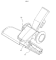
FIG. 1 is a perspective view of a known nozzle assembly; -
FIG. 2 is a cross section view illustrating the known nozzle assembly in use; -
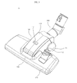
FIG. 3 is a partially cutaway perspective view of a nozzle assembly according to an embodiment of the present invention; -
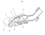
FIG. 4 is a cross-section of the nozzle assembly ofFIG. 3 ; -
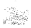
FIG. 5 is an exploded view illustrating main components of the nozzle assembly ofFIG. 3 ; -
FIG. 6 is a lower perspective view of a damper unit; -
FIG. 7 is a lower perspective view of a body cover; -
FIG. 8 is a partially cutaway perspective view illustrating a first air path; -
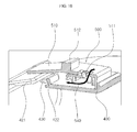
FIG. 9 is a partially enlarged cross-section illustrating a sealing portion in a closed state; -
FIG. 10 is a partially enlarged cross-section view illustrating the sealing portion in an open state; and -
FIG. 11 is a perspective view of a vacuum cleaner in which a nozzle assembly is mounted. - Reference will now be made in detail to the embodiments of the present invention illustrated in the drawings, wherein like reference numerals refer to like elements throughout. The embodiments are described below in order to explain aspects of the present invention by referring to the figures.
-
FIG. 3 is a partially cutaway perspective view of a nozzle assembly according to an embodiment of the present invention,FIG. 4 is a cross-section of the nozzle assembly,FIG. 5 is an exploded view illustrating main components,FIG. 6 is a lower perspective view of a damper unit,FIG. 7 is a lower perspective view of a body cover,FIG. 8 is a partially cutaway perspective view illustrating a first air path,FIG. 9 is a partially enlarged cross-section illustrating a sealing portion in a closed state,FIG. 10 is a partially enlarged cross section view illustrating the sealing portion in an open state andFIG. 11 is a perspective view of a vacuum cleaner in which a nozzle assembly is mounted. - Referring to
FIGS. 3 to 5 , anozzle assembly 1 according to an embodiment of the present invention includes anozzle portion 100, anozzle head 200 and a connectingtube 300. - The
nozzle portion 100 may include anozzle body 400, and abody cover 110, Thenozzle body 400 may include a suction path 406 (FIG. 4 ) connected fluidly to amain body 11 of a vacuum cleaner (FIG. 11 ). Thesuction path 406 forms a passage through a which drawn-in air stream and dust suspended in the air stream is moved, and is formed on an inner side of thenozzle body 400. Thenozzle body 400 also includes aseating portion 401 formed on an upper portion of thenozzle body 400 and adamper unit 500, which will be explained in greater detail below, which is seated on theseating portion 401. Couplingholes nozzle body 400 at predetermined intervals for connection to thebody cover 110. - The body cover 110 (
FIG. 7 ) defines a portion of the exterior of the nozzle assembly according to an embodiment of the present invention and includes anobservation window 111 through which movement of a damper member 520 (which will be explained below) can be observed.External air ports 112 are formed on lower ends of thebody cover 110. Thebody cover 110 also includescoupling ribs coupling holes nozzle body 400. If thecoupling holes coupling ribs FIG. 8 ) is formed between thecoupling ribs external air port 112 may be passed therethrough. - One end of the
nozzle body 400 is connected by ahinge 407 so that anozzle head 200 is pivotable. A sealing portion 420 (FIG. 9 ) is formed on a contact surface of thenozzle body 400 and thenozzle head 200. The sealingportion 420 includes a sealingmember 421 extending from thenozzle head 200 and a sealingguide portion 422 formed on one end of thenozzle body 400. The sealingmember 421 and the sealingguide portion 422 are in sliding contact with each other when thenozzle head 200 is pivoted. A pair ofwheels 430 is situated on a lower portion of thenozzle body 400 so thenozzle body 400 may be moved along a surface being cleaned. - The other end of the
nozzle body 400 is connected to one end of the connectingtube 300 so as to be in fluid communication with thesuction path 406. Since the connectingtube 300 is connected to thenozzle body 400 by thehinge 408, that is, since the connectingtube 300 is pivotable with respect to thenozzle body 400, the connectingtube 300 is smoothly pivoted as the user pushes or pulls thenozzle assembly 1 during a cleaning operation (FIG. 8 ). The other end of the connectingtube 300 is connected to theextension tube assembly 12 of the vacuum cleaner and thus is in fluid communication with the vacuumcleaner body 11. - The damper unit 500 (
FIGS. 5 and6 ) includes adamper holder 510, adamper member 520, and aspring 530. Thedamper holder 510 includes a plurality of damper holes 511 and an indicatingprotrusion 512 formed at a center portion.Stoppers 513 are formed within thedamper holder 510 to restrict movement of thedamper member 520 and anair passage 514 is formed between thestoppers 513 so that thestoppers 513 do not interfere with the incoming air stream. Thedamper holder 510 is made from a transparent material to enable a user to observe the movement of thedamper member 520 through theobservation window 111. - The
spring 530 is engaged withspring fixing members damper member 520 to thedamper holder 510. Thedamper member 520 closes the damper holes 511 in an ordinary condition due to the elastic force of thespring 530, but is slid against the elastic force of thespring 530 when a higher suction force occurs. Thedamper member 520 also includesair passages air passages damper hole 511 and thedamper unit 500 form a second air path 540 (FIG. 10 ). - The
nozzle head 200 is pivotably engaged with thenozzle body 400 by a hinge 407 (FIG. 8 ). Thenozzle head 200 includes asuction port 222 formed therein and in fluid connection with thesuction path 406 of thenozzle body 400. Thenozzle head 200 also includes a sealingmember 421 formed on an upper portion thereof which is brought into a slidingcontact with the sealingguide portion 422 formed on thenozzle body 400 as thenozzle head 200 pivots. - If a user pushes the
nozzle assembly 1, thenozzle head 200 is pivoted with respect to thenozzle body 400 by approximately four (4) degrees. If the user pulls thenozzle assembly 1, thenozzle head 200 is pivoted with respect to thenozzle body 400 by approximately seven (7) degrees. An inclining portion 221 (FIG. 4 ) may be formed on a lower front portion of thenozzle head 200 so that thenozzle head 200 is pivoted smoothly with respect to thenozzle body 400 when the user pushes thenozzle assembly 1. A pair of wheels (not illustrated) are formed on a lower portion of thenozzle head 200 to enable thenozzle assembly 1 to move along a surface being cleaned. Ahead cover 210 forms part of thenozzle head 200 and provides a more aesthetic appearance for thenozzle head 200. - The operation of the nozzle assembly for a vacuum cleaner according to an embodiment of the present invention will now be explained in greater detail with reference to the accompanying drawings. It is assumed that the vacuum cleaner cleans a carpeted floor as an example of a soft surface over which is generally not easy for a user to maneuver the vacuum cleaner without exerting a significant effort.
- If the
nozzle assembly 1 is not moving, the sealingportion 420 is in a closed state and thefirst air path 403 is in fluid communication with the external atmosphere through theexternal air port 112. Accordingly, the upper portion of thedamper unit 500 is under atmospheric pressure. - If the user grabs the
handle 13 of the extension tube assembly and pushes thehandle 13, thenozzle assembly 1 is moved along the carpeted floor by rotation of the wheels provided on the lower portion. - The user's force to push the brush assembly forward is applied to the
nozzle assembly 1 with a downward component, and thenozzle assembly 1 is concurrently influenced by the suction force applied to thesuction port 222 of thenozzle head 200. Accordingly, if the user pushes forward on thehandle 13, thenozzle head 200 of thenozzle assembly 1 is pivoted about thehinge 407 in a downward direction with respect to thenozzle body 400, so that the externalair introduction space 430 is formed in the sealingportion 420 to introduce an external air stream into thesuction path 406 of thenozzle body 400. - Specifically, if the
nozzle head 200 is pivoted with respect to thenozzle body 400, as illustrated inFIG. 10 , the sealingmember 421 is moved away from the sealingguide 422 of thenozzle body 400, thereby forming the externalair introduction space 430. As a result, the suction force of thesuction path 406 is applied to thedamper member 520 of thedamper unit 500 and thedamper member 520 is moved against the elastic force of the spring toward the externalair introduction space 430. - Due to the movement of the
damper member 520, thedamper hole 511 is opened and an external air stream is introduced into thesuction path 406 through thesecond air path 540. As a result, the negative pressure applied to thesuction port 222 is reduced and the user can clean the carpeted surface with reduced effort and increased convenience. - If the user pulls the
handle 13, thenozzle assembly 1 is moved in a backward direction and thenozzle head 200 is rotated in a reverse direction to when thenozzle head 200 is pushed with respect to thenozzle body 400. At this time, the sealingmember 421 is brought into close contact with the sealingguide 422, thereby closing the externalair introduction space 430. Accordingly, thedamper member 520 is returned to its resting position by the elastic recovery force of the spring and thedamper hole 511 is closed. - If the
damper hole 511 is closed and the negative pressure at thesuction port 222 is not reduced, the user can pull thenozzle assembly 1 without too much effort, since the suction force of thesuction port 222 is counterbalanced by the user's force used to pull thenozzle assembly 1. - The
damper holder 510 has a plurality of damper holes 511 - the number of the damper holes 511 which are open vary according to the distance which thedamper member 520 has moved. The distance which thedamper member 520 has moved varies according to the suction force of thesuction path 406. The suction force of thesuction path 406 varies according to the power of the vacuum cleaner in use. - By way of example, a
nozzle assembly 1 for use in a vacuum cleaner with a 2000W output power has a relatively greater distance over which thedamper member 520 moves, in which case three (3) damper holes 511 are opened. In this case, a relatively large amount of external air is introduced and negative pressure at thesuction port 222 is significantly reduced. On the other hand, in vacuum cleaner models with 1600W - 1400W power outputs, one or twodamper holes 511 are opened, and the reduction of the negative pressure at thesuction port 222 is, relatively, less. Since the amount of incoming air varies in accordance with the output power of the vacuum cleaner model, the user can use any vacuum cleaner with an equal amount of maneuvering force, regardless of the output power of the vacuum cleaner in use. That is, thenozzle assembly 1 according to an embodiment of the present invention is compatible with a variety of different vacuum cleaner models. - The above operation also applies when the user changes the suction force of the vacuum cleaner during the cleaning operation. Accordingly, the amount of incoming external air is adjusted by the
damper unit 500 in accordance with the change of suction force and the user can use the vacuum cleaner with the required amount of maneuvering force without influencing cleaning efficiency. - A vacuum cleaner having a nozzle assembly according to another embodiment of the present invention will be explained in greater detail below.
- Referring to
FIG. 11 , thevacuum cleaner 10 according to an embodiment of the present invention includes amain body 11, anextension tube assembly 12, and anozzle assembly 1. - The
main body 11 of thevacuum cleaner 10 generates a suction force to drawn in external dust along with air stream. Accordingly, themain body 11 includes a vacuum generating device (not illustrated) to generate a suction. - Additionally, the
main body 11 includes a dust separating/collecting device (not illustrated) to separate dust from the drawn-in air stream and collect the dust therein when the air stream is drawn in through thenozzle assembly 1 and theextension tube assembly 12. - The
extension tube assembly 12 places themain body 11 in fluid connection with thenozzle assembly 1. Theextension tube assembly 12 includes an extension tube in fluid connection with thenozzle assembly 1 to guide the drawn in dust, ahandle 13 with which a user holds and pushes or pulls thenozzle assembly 1 as necessary during a cleaning operation and asuction hose 14 to guide the dust-laden air stream which passed through the extension tube into themain body 11. - The
nozzle assembly 1 is in fluid connection with theextension tube assembly 12, to draw in dust or dirt from a surface being cleaned. The operation of thenozzle assembly 1 as the user holds thehandle 13 and pushes or pulls thenozzle assembly 1 is described above. - As explained above, with the
nozzle assembly 1 for use in a vacuum cleaner and a vacuum cleaner having thenozzle assembly 1 according to embodiments of the present invention, the user can clean soft-surfaced areas such as carpeted floor without exerting too much effort, since the force required to maneuver the nozzle assembly is adjusted appropriately. - Furthermore, since the force required to maneuver the
nozzle assembly 1 is automatically adjusted in accordance with the output power of a vacuum cleaner where thenozzle assembly 1 is applied, thenozzle assembly 1 is compatible for use with a variety of vacuum cleaner models. As a result, manufacturing productivity increases. - While there have been illustrated and described what are considered to be example embodiments of the present invention, it will be understood by those skilled in the art, and as technology develops, that various changes and modifications may be made and equivalents may be substituted for elements without departing from the scope of the present invention. Many modifications, permutations, additions and sub-combinations may be made to adapt the teachings of the present invention to a particular situation without departing from the scope thereof.
Claims (12)
- A nozzle assembly (1) for a vacuum cleaner, comprising:a nozzle body (100) having a suction path formed therein;a nozzle head (200) pivotably attached to one end of the nozzle body (400);a sealing portion (420) for forming a seal between the nozzle body (400) and the nozzle head (200) and having an external air introduction space (430) formed therein when a user pushes the nozzle assembly; anda damper unit (500) configured to adjust an amount of an air stream introduced into the external air introduction space in proportion to a suction force of the suction path.
- A nozzle assembly as claimed in claim 1, wherein the sealing portion (420) comprises:a sealing member (421) extending from an upper end of the nozzle head; anda sealing guide (422) extending from the nozzle body and configured to be brought into sliding contact with the sealing member.
- A nozzle assembly as claimed in claim 1 or claim 2, wherein the damper unit (500) comprises:a damper holder (510) comprising one or more damper holes (511); anda damper member (520) formed to be slid inside the damper holder.
- A nozzle assembly as claimed in claim 3, wherein the damper unit (500) is formed so that, if the external air introduction space is formed in the sealing portion (420), the damper holes (511) may be opened in dependence on the movement of the damper member (520), and an external air stream may be introduced into the damper holes.
- A nozzle assembly as claimed in claim 3 or claim 4, wherein the damper holder (510) comprises an indicating protrusion (512) made from a transparent material.
- A nozzle assembly as claimed in any of claims 1 to 5, further comprising a body cover (110) formed to be engaged with the nozzle head (200) and with an upper portion of the nozzle body (400).
- A nozzle assembly as claimed in claim 6, wherein the body cover (110) comprises an observation window (111) formed therein.
- A nozzle assembly as claimed in claim 7, wherein the body cover (110) comprises an external air port (112) formed therein, and a first air path (403) is formed between the body cover and the nozzle body.
- A vacuum cleaner (10) comprising:a main body (11) for generating a suction force;an extension tube assembly (12) in fluid communication with the main body, the extension tube assembly comprising a passage through which air with dust or dirt is moved; anda nozzle assembly (1) in fluid communication with the extension tube assembly, whereinthe nozzle assembly (1) comprises:a nozzle body (100) having a suction path formed therein;a nozzle head (200) rotatably formed on one end of the nozzle body (400);a sealing portion (420) for forming a seal between the nozzle body (400) and the nozzle head (200) and having an external air introduction space (430) formed therein when a user pushes the nozzle assembly; anda damper unit (500) configured to adjust an amount of air stream introduced into the external air introduction space in proportion to a suction force of the suction path.
- A cleaning attachment for use with a vacuum cleaner, said cleaning attachment comprising:a head having an operational facet for contacting a surface to be cleaned,an inlet port formed in said operational facet;an air passage in fluid communication with said inlet to form a passageway through which air is transferred to the vacuum cleaner, said air passage being pivotably connected to said head,a variable sealing member at least partly disposed between said head and said air passage and configured so that pivoting of said head relative to said air passage in a first direction increases a sealing effect of said variable sealing member and pivoting of said head relative to said passage in a second direction decreases a sealing effect of said variable sealing member;said variable sealing member further comprising valve means for altering a sealing effect of said variable sealing member in dependence on a suction generated by said vacuum cleaner.
- A cleaning attachment as claimed in claim 10 wherein said valve means comprises a slidable shutter disposed to cover one or more of a plurality of inlet ports to vary said sealing effect.
- A cleaning attachment as claimed in claim 11 wherein said slidable shutter comprises a biasing means which acts to return said slidable shutter to a position where all inlet ports are covered.
Applications Claiming Priority (1)
| Application Number | Priority Date | Filing Date | Title |
|---|---|---|---|
| KR1020090079418A KR101590335B1 (en) | 2009-08-26 | 2009-08-26 | Vacuum cleaner brush assembly and vacuum cleaner having the same |
Publications (3)
| Publication Number | Publication Date |
|---|---|
| EP2289380A2 true EP2289380A2 (en) | 2011-03-02 |
| EP2289380A3 EP2289380A3 (en) | 2013-07-10 |
| EP2289380B1 EP2289380B1 (en) | 2016-05-04 |
Family
ID=43033564
Family Applications (1)
| Application Number | Title | Priority Date | Filing Date |
|---|---|---|---|
| EP10158935.6A Not-in-force EP2289380B1 (en) | 2009-08-26 | 2010-04-01 | Nozzle assembly for a vacuum cleaner |
Country Status (4)
| Country | Link |
|---|---|
| EP (1) | EP2289380B1 (en) |
| KR (1) | KR101590335B1 (en) |
| AU (1) | AU2010201506B1 (en) |
| RU (1) | RU2419375C1 (en) |
Citations (1)
| Publication number | Priority date | Publication date | Assignee | Title |
|---|---|---|---|---|
| KR100667885B1 (en) | 2005-09-27 | 2007-01-16 | 삼성광주전자 주식회사 | Brush assembly for vacuum cleaner and vacuum cleaner having same |
Family Cites Families (8)
| Publication number | Priority date | Publication date | Assignee | Title |
|---|---|---|---|---|
| FR74946E (en) * | 1958-02-22 | 1961-03-03 | Electrolux Ab | Vacuum regulator for dust extractors |
| GB2383257B (en) * | 2001-12-21 | 2005-08-10 | Dyson Ltd | Cleaner head for a vacuum cleaner |
| GB2393383B (en) * | 2002-09-24 | 2005-12-28 | Dyson Ltd | A vacuum cleaning head |
| JP2005000266A (en) * | 2003-06-10 | 2005-01-06 | Toshiba Tec Corp | Suction port and vacuum cleaner |
| KR20070010279A (en) * | 2005-07-18 | 2007-01-24 | 엘지전자 주식회사 | Dust collection unit of vacuum cleaner |
| JP2008086549A (en) * | 2006-10-02 | 2008-04-17 | Matsushita Electric Ind Co Ltd | Vacuum cleaner suction tool and vacuum cleaner using the same |
| US20080184521A1 (en) * | 2007-02-02 | 2008-08-07 | Streciwilk Eric J | Canister vacuum cleaner equipped with air cushion caster wheel assembly |
| DE102007010517B4 (en) * | 2007-03-05 | 2013-04-11 | Wessel-Werk Gmbh | Nozzle for a cylinder vacuum cleaner |
-
2009
- 2009-08-26 KR KR1020090079418A patent/KR101590335B1/en not_active Expired - Fee Related
-
2010
- 2010-04-01 EP EP10158935.6A patent/EP2289380B1/en not_active Not-in-force
- 2010-04-15 AU AU2010201506A patent/AU2010201506B1/en not_active Ceased
- 2010-05-05 RU RU2010118058/12A patent/RU2419375C1/en not_active IP Right Cessation
Patent Citations (1)
| Publication number | Priority date | Publication date | Assignee | Title |
|---|---|---|---|---|
| KR100667885B1 (en) | 2005-09-27 | 2007-01-16 | 삼성광주전자 주식회사 | Brush assembly for vacuum cleaner and vacuum cleaner having same |
Also Published As
| Publication number | Publication date |
|---|---|
| RU2419375C1 (en) | 2011-05-27 |
| KR101590335B1 (en) | 2016-02-18 |
| AU2010201506B1 (en) | 2011-03-17 |
| EP2289380A3 (en) | 2013-07-10 |
| EP2289380B1 (en) | 2016-05-04 |
| KR20110021555A (en) | 2011-03-04 |
Similar Documents
| Publication | Publication Date | Title |
|---|---|---|
| EP3209176B1 (en) | Vacuum cleaner having a conversion valve | |
| KR101369227B1 (en) | Suction Brush for Vacuum Cleaner | |
| KR20100006787A (en) | Cleaner | |
| GB2453617A (en) | Convertible upright vacuum cleaner | |
| US7559112B2 (en) | Passage conversion valve assembly for a vacuum cleaner | |
| US8032982B2 (en) | Upright vacuum cleaner having suction path switching valve | |
| US20190111373A1 (en) | Filter assembly for a vacuum cleaner | |
| CN101953664A (en) | surface treatment head | |
| US8978207B2 (en) | Vacuum cleaner edge cleaning system | |
| KR100667885B1 (en) | Brush assembly for vacuum cleaner and vacuum cleaner having same | |
| EP2289380B1 (en) | Nozzle assembly for a vacuum cleaner | |
| EP4226830A1 (en) | Modular cleaner | |
| JP4945223B2 (en) | Electric vacuum cleaner | |
| GB2461658A (en) | Convertible vacuum cleaner | |
| EP4452031B1 (en) | Suction tube arrangement for a vacuum cleaner | |
| EP2266449B1 (en) | Inlet means with multiple ports | |
| JP2019188117A (en) | Suction hole body of vacuum cleaner and vacuum cleaner comprising the same | |
| KR0115548Y1 (en) | Suction control device for a vacuum cleaner with a mop | |
| JP2009078081A (en) | Vacuum cleaner and its suction port | |
| EP2409618B1 (en) | Vacuum cleaner | |
| KR0136315Y1 (en) | Suction hose flow device of vacuum cleaner | |
| KR100517825B1 (en) | suction apparatus for floor | |
| GB2453619A (en) | Vacuum cleaner | |
| KR20070013388A (en) | Extension tube of vacuum cleaner |
Legal Events
| Date | Code | Title | Description |
|---|---|---|---|
| PUAI | Public reference made under article 153(3) epc to a published international application that has entered the european phase |
Free format text: ORIGINAL CODE: 0009012 |
|
| AK | Designated contracting states |
Kind code of ref document: A2 Designated state(s): AT BE BG CH CY CZ DE DK EE ES FI FR GB GR HR HU IE IS IT LI LT LU LV MC MK MT NL NO PL PT RO SE SI SK SM TR |
|
| AX | Request for extension of the european patent |
Extension state: AL BA ME RS |
|
| RAP1 | Party data changed (applicant data changed or rights of an application transferred) |
Owner name: SAMSUNG ELECTRONICS CO., LTD. |
|
| RAP1 | Party data changed (applicant data changed or rights of an application transferred) |
Owner name: SAMSUNG ELECTRONICS CO., LTD. |
|
| PUAL | Search report despatched |
Free format text: ORIGINAL CODE: 0009013 |
|
| AK | Designated contracting states |
Kind code of ref document: A3 Designated state(s): AT BE BG CH CY CZ DE DK EE ES FI FR GB GR HR HU IE IS IT LI LT LU LV MC MK MT NL NO PL PT RO SE SI SK SM TR |
|
| AX | Request for extension of the european patent |
Extension state: AL BA ME RS |
|
| RIC1 | Information provided on ipc code assigned before grant |
Ipc: A47L 9/06 20060101ALI20130606BHEP Ipc: A47L 9/00 20060101AFI20130606BHEP |
|
| 17P | Request for examination filed |
Effective date: 20140109 |
|
| RBV | Designated contracting states (corrected) |
Designated state(s): AT BE BG CH CY CZ DE DK EE ES FI FR GB GR HR HU IE IS IT LI LT LU LV MC MK MT NL NO PL PT RO SE SI SK SM TR |
|
| 17Q | First examination report despatched |
Effective date: 20150316 |
|
| GRAP | Despatch of communication of intention to grant a patent |
Free format text: ORIGINAL CODE: EPIDOSNIGR1 |
|
| INTG | Intention to grant announced |
Effective date: 20151127 |
|
| GRAS | Grant fee paid |
Free format text: ORIGINAL CODE: EPIDOSNIGR3 |
|
| GRAA | (expected) grant |
Free format text: ORIGINAL CODE: 0009210 |
|
| AK | Designated contracting states |
Kind code of ref document: B1 Designated state(s): AT BE BG CH CY CZ DE DK EE ES FI FR GB GR HR HU IE IS IT LI LT LU LV MC MK MT NL NO PL PT RO SE SI SK SM TR |
|
| REG | Reference to a national code |
Ref country code: GB Ref legal event code: FG4D |
|
| REG | Reference to a national code |
Ref country code: CH Ref legal event code: EP |
|
| REG | Reference to a national code |
Ref country code: AT Ref legal event code: REF Ref document number: 796114 Country of ref document: AT Kind code of ref document: T Effective date: 20160515 |
|
| REG | Reference to a national code |
Ref country code: IE Ref legal event code: FG4D |
|
| REG | Reference to a national code |
Ref country code: DE Ref legal event code: R096 Ref document number: 602010032989 Country of ref document: DE |
|
| REG | Reference to a national code |
Ref country code: NL Ref legal event code: MP Effective date: 20160504 |
|
| REG | Reference to a national code |
Ref country code: LT Ref legal event code: MG4D |
|
| PG25 | Lapsed in a contracting state [announced via postgrant information from national office to epo] |
Ref country code: LT Free format text: LAPSE BECAUSE OF FAILURE TO SUBMIT A TRANSLATION OF THE DESCRIPTION OR TO PAY THE FEE WITHIN THE PRESCRIBED TIME-LIMIT Effective date: 20160504 Ref country code: NL Free format text: LAPSE BECAUSE OF FAILURE TO SUBMIT A TRANSLATION OF THE DESCRIPTION OR TO PAY THE FEE WITHIN THE PRESCRIBED TIME-LIMIT Effective date: 20160504 Ref country code: FI Free format text: LAPSE BECAUSE OF FAILURE TO SUBMIT A TRANSLATION OF THE DESCRIPTION OR TO PAY THE FEE WITHIN THE PRESCRIBED TIME-LIMIT Effective date: 20160504 Ref country code: NO Free format text: LAPSE BECAUSE OF FAILURE TO SUBMIT A TRANSLATION OF THE DESCRIPTION OR TO PAY THE FEE WITHIN THE PRESCRIBED TIME-LIMIT Effective date: 20160804 |
|
| REG | Reference to a national code |
Ref country code: AT Ref legal event code: MK05 Ref document number: 796114 Country of ref document: AT Kind code of ref document: T Effective date: 20160504 |
|
| PG25 | Lapsed in a contracting state [announced via postgrant information from national office to epo] |
Ref country code: SE Free format text: LAPSE BECAUSE OF FAILURE TO SUBMIT A TRANSLATION OF THE DESCRIPTION OR TO PAY THE FEE WITHIN THE PRESCRIBED TIME-LIMIT Effective date: 20160504 Ref country code: GR Free format text: LAPSE BECAUSE OF FAILURE TO SUBMIT A TRANSLATION OF THE DESCRIPTION OR TO PAY THE FEE WITHIN THE PRESCRIBED TIME-LIMIT Effective date: 20160805 Ref country code: ES Free format text: LAPSE BECAUSE OF FAILURE TO SUBMIT A TRANSLATION OF THE DESCRIPTION OR TO PAY THE FEE WITHIN THE PRESCRIBED TIME-LIMIT Effective date: 20160504 Ref country code: PT Free format text: LAPSE BECAUSE OF FAILURE TO SUBMIT A TRANSLATION OF THE DESCRIPTION OR TO PAY THE FEE WITHIN THE PRESCRIBED TIME-LIMIT Effective date: 20160905 Ref country code: LV Free format text: LAPSE BECAUSE OF FAILURE TO SUBMIT A TRANSLATION OF THE DESCRIPTION OR TO PAY THE FEE WITHIN THE PRESCRIBED TIME-LIMIT Effective date: 20160504 Ref country code: HR Free format text: LAPSE BECAUSE OF FAILURE TO SUBMIT A TRANSLATION OF THE DESCRIPTION OR TO PAY THE FEE WITHIN THE PRESCRIBED TIME-LIMIT Effective date: 20160504 |
|
| PG25 | Lapsed in a contracting state [announced via postgrant information from national office to epo] |
Ref country code: IT Free format text: LAPSE BECAUSE OF FAILURE TO SUBMIT A TRANSLATION OF THE DESCRIPTION OR TO PAY THE FEE WITHIN THE PRESCRIBED TIME-LIMIT Effective date: 20160504 |
|
| PG25 | Lapsed in a contracting state [announced via postgrant information from national office to epo] |
Ref country code: CZ Free format text: LAPSE BECAUSE OF FAILURE TO SUBMIT A TRANSLATION OF THE DESCRIPTION OR TO PAY THE FEE WITHIN THE PRESCRIBED TIME-LIMIT Effective date: 20160504 Ref country code: DK Free format text: LAPSE BECAUSE OF FAILURE TO SUBMIT A TRANSLATION OF THE DESCRIPTION OR TO PAY THE FEE WITHIN THE PRESCRIBED TIME-LIMIT Effective date: 20160504 Ref country code: RO Free format text: LAPSE BECAUSE OF FAILURE TO SUBMIT A TRANSLATION OF THE DESCRIPTION OR TO PAY THE FEE WITHIN THE PRESCRIBED TIME-LIMIT Effective date: 20160504 Ref country code: SK Free format text: LAPSE BECAUSE OF FAILURE TO SUBMIT A TRANSLATION OF THE DESCRIPTION OR TO PAY THE FEE WITHIN THE PRESCRIBED TIME-LIMIT Effective date: 20160504 Ref country code: EE Free format text: LAPSE BECAUSE OF FAILURE TO SUBMIT A TRANSLATION OF THE DESCRIPTION OR TO PAY THE FEE WITHIN THE PRESCRIBED TIME-LIMIT Effective date: 20160504 |
|
| REG | Reference to a national code |
Ref country code: DE Ref legal event code: R097 Ref document number: 602010032989 Country of ref document: DE |
|
| PG25 | Lapsed in a contracting state [announced via postgrant information from national office to epo] |
Ref country code: AT Free format text: LAPSE BECAUSE OF FAILURE TO SUBMIT A TRANSLATION OF THE DESCRIPTION OR TO PAY THE FEE WITHIN THE PRESCRIBED TIME-LIMIT Effective date: 20160504 Ref country code: PL Free format text: LAPSE BECAUSE OF FAILURE TO SUBMIT A TRANSLATION OF THE DESCRIPTION OR TO PAY THE FEE WITHIN THE PRESCRIBED TIME-LIMIT Effective date: 20160504 Ref country code: BE Free format text: LAPSE BECAUSE OF FAILURE TO SUBMIT A TRANSLATION OF THE DESCRIPTION OR TO PAY THE FEE WITHIN THE PRESCRIBED TIME-LIMIT Effective date: 20160504 Ref country code: SM Free format text: LAPSE BECAUSE OF FAILURE TO SUBMIT A TRANSLATION OF THE DESCRIPTION OR TO PAY THE FEE WITHIN THE PRESCRIBED TIME-LIMIT Effective date: 20160504 |
|
| PLBE | No opposition filed within time limit |
Free format text: ORIGINAL CODE: 0009261 |
|
| STAA | Information on the status of an ep patent application or granted ep patent |
Free format text: STATUS: NO OPPOSITION FILED WITHIN TIME LIMIT |
|
| 26N | No opposition filed |
Effective date: 20170207 |
|
| PG25 | Lapsed in a contracting state [announced via postgrant information from national office to epo] |
Ref country code: SI Free format text: LAPSE BECAUSE OF FAILURE TO SUBMIT A TRANSLATION OF THE DESCRIPTION OR TO PAY THE FEE WITHIN THE PRESCRIBED TIME-LIMIT Effective date: 20160504 |
|
| PG25 | Lapsed in a contracting state [announced via postgrant information from national office to epo] |
Ref country code: MC Free format text: LAPSE BECAUSE OF FAILURE TO SUBMIT A TRANSLATION OF THE DESCRIPTION OR TO PAY THE FEE WITHIN THE PRESCRIBED TIME-LIMIT Effective date: 20160504 |
|
| REG | Reference to a national code |
Ref country code: CH Ref legal event code: PL |
|
| REG | Reference to a national code |
Ref country code: IE Ref legal event code: MM4A |
|
| REG | Reference to a national code |
Ref country code: FR Ref legal event code: ST Effective date: 20171229 |
|
| PG25 | Lapsed in a contracting state [announced via postgrant information from national office to epo] |
Ref country code: FR Free format text: LAPSE BECAUSE OF NON-PAYMENT OF DUE FEES Effective date: 20170502 |
|
| PG25 | Lapsed in a contracting state [announced via postgrant information from national office to epo] |
Ref country code: LU Free format text: LAPSE BECAUSE OF NON-PAYMENT OF DUE FEES Effective date: 20170401 Ref country code: LI Free format text: LAPSE BECAUSE OF NON-PAYMENT OF DUE FEES Effective date: 20170430 Ref country code: CH Free format text: LAPSE BECAUSE OF NON-PAYMENT OF DUE FEES Effective date: 20170430 |
|
| PG25 | Lapsed in a contracting state [announced via postgrant information from national office to epo] |
Ref country code: IE Free format text: LAPSE BECAUSE OF NON-PAYMENT OF DUE FEES Effective date: 20170401 |
|
| PGFP | Annual fee paid to national office [announced via postgrant information from national office to epo] |
Ref country code: GB Payment date: 20180321 Year of fee payment: 9 |
|
| PGFP | Annual fee paid to national office [announced via postgrant information from national office to epo] |
Ref country code: DE Payment date: 20180320 Year of fee payment: 9 |
|
| PG25 | Lapsed in a contracting state [announced via postgrant information from national office to epo] |
Ref country code: MT Free format text: LAPSE BECAUSE OF NON-PAYMENT OF DUE FEES Effective date: 20170401 |
|
| PG25 | Lapsed in a contracting state [announced via postgrant information from national office to epo] |
Ref country code: HU Free format text: LAPSE BECAUSE OF FAILURE TO SUBMIT A TRANSLATION OF THE DESCRIPTION OR TO PAY THE FEE WITHIN THE PRESCRIBED TIME-LIMIT; INVALID AB INITIO Effective date: 20100401 |
|
| PG25 | Lapsed in a contracting state [announced via postgrant information from national office to epo] |
Ref country code: BG Free format text: LAPSE BECAUSE OF FAILURE TO SUBMIT A TRANSLATION OF THE DESCRIPTION OR TO PAY THE FEE WITHIN THE PRESCRIBED TIME-LIMIT Effective date: 20160504 |
|
| PG25 | Lapsed in a contracting state [announced via postgrant information from national office to epo] |
Ref country code: CY Free format text: LAPSE BECAUSE OF NON-PAYMENT OF DUE FEES Effective date: 20160504 |
|
| REG | Reference to a national code |
Ref country code: DE Ref legal event code: R119 Ref document number: 602010032989 Country of ref document: DE |
|
| PG25 | Lapsed in a contracting state [announced via postgrant information from national office to epo] |
Ref country code: MK Free format text: LAPSE BECAUSE OF FAILURE TO SUBMIT A TRANSLATION OF THE DESCRIPTION OR TO PAY THE FEE WITHIN THE PRESCRIBED TIME-LIMIT Effective date: 20160504 |
|
| GBPC | Gb: european patent ceased through non-payment of renewal fee |
Effective date: 20190401 |
|
| PG25 | Lapsed in a contracting state [announced via postgrant information from national office to epo] |
Ref country code: GB Free format text: LAPSE BECAUSE OF NON-PAYMENT OF DUE FEES Effective date: 20190401 Ref country code: DE Free format text: LAPSE BECAUSE OF NON-PAYMENT OF DUE FEES Effective date: 20191101 |
|
| PG25 | Lapsed in a contracting state [announced via postgrant information from national office to epo] |
Ref country code: TR Free format text: LAPSE BECAUSE OF FAILURE TO SUBMIT A TRANSLATION OF THE DESCRIPTION OR TO PAY THE FEE WITHIN THE PRESCRIBED TIME-LIMIT Effective date: 20160504 |
|
| PG25 | Lapsed in a contracting state [announced via postgrant information from national office to epo] |
Ref country code: IS Free format text: LAPSE BECAUSE OF FAILURE TO SUBMIT A TRANSLATION OF THE DESCRIPTION OR TO PAY THE FEE WITHIN THE PRESCRIBED TIME-LIMIT Effective date: 20160904 |