EP2288838B1 - Pipeline monitoring apparatus and method - Google Patents
Pipeline monitoring apparatus and method Download PDFInfo
- Publication number
- EP2288838B1 EP2288838B1 EP09738434.1A EP09738434A EP2288838B1 EP 2288838 B1 EP2288838 B1 EP 2288838B1 EP 09738434 A EP09738434 A EP 09738434A EP 2288838 B1 EP2288838 B1 EP 2288838B1
- Authority
- EP
- European Patent Office
- Prior art keywords
- pipeline
- sensor
- vehicle according
- fingers
- wall
- Prior art date
- Legal status (The legal status is an assumption and is not a legal conclusion. Google has not performed a legal analysis and makes no representation as to the accuracy of the status listed.)
- Active
Links
Images




Classifications
-
- F—MECHANICAL ENGINEERING; LIGHTING; HEATING; WEAPONS; BLASTING
- F16—ENGINEERING ELEMENTS AND UNITS; GENERAL MEASURES FOR PRODUCING AND MAINTAINING EFFECTIVE FUNCTIONING OF MACHINES OR INSTALLATIONS; THERMAL INSULATION IN GENERAL
- F16L—PIPES; JOINTS OR FITTINGS FOR PIPES; SUPPORTS FOR PIPES, CABLES OR PROTECTIVE TUBING; MEANS FOR THERMAL INSULATION IN GENERAL
- F16L55/00—Devices or appurtenances for use in, or in connection with, pipes or pipe systems
- F16L55/26—Pigs or moles, i.e. devices movable in a pipe or conduit with or without self-contained propulsion means
- F16L55/28—Constructional aspects
- F16L55/30—Constructional aspects of the propulsion means, e.g. towed by cables
- F16L55/38—Constructional aspects of the propulsion means, e.g. towed by cables driven by fluid pressure
-
- G—PHYSICS
- G01—MEASURING; TESTING
- G01B—MEASURING LENGTH, THICKNESS OR SIMILAR LINEAR DIMENSIONS; MEASURING ANGLES; MEASURING AREAS; MEASURING IRREGULARITIES OF SURFACES OR CONTOURS
- G01B7/00—Measuring arrangements characterised by the use of electric or magnetic techniques
- G01B7/28—Measuring arrangements characterised by the use of electric or magnetic techniques for measuring contours or curvatures
- G01B7/281—Measuring arrangements characterised by the use of electric or magnetic techniques for measuring contours or curvatures for measuring contour or curvature along an axis, e.g. axial curvature of a pipeline or along a series of feeder rollers
-
- F—MECHANICAL ENGINEERING; LIGHTING; HEATING; WEAPONS; BLASTING
- F16—ENGINEERING ELEMENTS AND UNITS; GENERAL MEASURES FOR PRODUCING AND MAINTAINING EFFECTIVE FUNCTIONING OF MACHINES OR INSTALLATIONS; THERMAL INSULATION IN GENERAL
- F16L—PIPES; JOINTS OR FITTINGS FOR PIPES; SUPPORTS FOR PIPES, CABLES OR PROTECTIVE TUBING; MEANS FOR THERMAL INSULATION IN GENERAL
- F16L2101/00—Uses or applications of pigs or moles
- F16L2101/30—Inspecting, measuring or testing
Definitions
- This invention relates to an apparatus and method for monitoring and/or measuring the presence of debris within pipelines.
- debris is used herein to denote any type of non-ferrous debris, fouling or scale on the internal surface of a pipeline which reduces the bore of the pipeline.
- An object of the present invention is to provide a means for convenient and effective monitoring and logging of debris within a pipeline.
- pigs autonomous vehicles propelled by pipeline pressure and flow
- pigs are well known (see for instance WO 96/13699 A , GB 2410070 A and US 3974680 A ).
- Pigs are known in which hinged fingers or callipers are biased outwardly intro contact with the inner wall surface. These are used to measure the internal diameter of the pipeline, which can reveal the presence and location of gross obstructions.
- these known pigs are not sufficiently accurate to meet the objectives of the present invention.
- this technique assumes that the inner diameter of the pipeline is still the same as originally, and thus a section which has debris on top of corrosion-wasted wall thickness may be detected as normal. Also, a debris coating of 5 mm or less may be significant to the success of chemical treatment and/or inspection programs, but may be within the tolerance of the pipeline specification.
- a pipeline inspection vehicle having the features recited in the preamble of claims 1 and 13 is known from US6847207B1 .
- a further inspection system using magnetic sensors in the proximity of the pipeline wall is known from US2007/022830A1 .
- the present invention provides a pipeline inspection vehicle comprising the features of claim 1, and a method of monitoring debris in a pipeline comprising the features of claim 13.
- a pipeline pig comprises a metal body or mandrel 10.
- Resilient cups 12 typically of polyurethane are clamped to and extend from the body 10 for engagement with the inner wall of a pipeline such that the pig is transported through the pipeline by product pressure and flow rate.
- a hub 14 extends rearwardly of the body 10 and mounts three equispaced arms 16 each carrying a wheel 18, the arms 16 being biased outwardly to engage the wheels 18 with the pipeline wall.
- the wheels 18 drive rotary sensors (not shown) to provide odometer information.
- two or four odometer wheels could be used.
- the pig as thus far described is known per se.
- the pig is also provided with an annular ring of resilient fingers 20 each of which has an outwardly extending portion 20a and an outer axial portion 20b.
- the fingers 20 could be, for example, integral spring steel fingers. Alternatively, rigid fingers hinged to the body 10 and biased by springs or the like could be used. In typical embodiments, the fingers 20 are about 30mm wide, giving a total of 25 fingers for a 10 inch pipeline, increasing proportionately up to 110 fingers for a 42 inch pipeline, and so on for greater diameters. In general terms, it is preferred to use as great a number of detectors as can be accommodated for maximum resolution.
- each of the fingers 20 carries within its axial portion 20b a sensor assembly 22.
- Each sensor assembly 22 is therefore drawn along the pipeline in a fixed relation to the inner surface 28 of the pipeline, i.e. the inner surface provided by the pipe itself or by any debris attached to the pipe wall. It will be appreciated that the fingers 20 can flex independently of each other, and thus each sensor assembly 22 monitors a small part of the circumference independently of the other parts.
- the sensor assembly 22 comprises a Hall effect sensor 24 and a magnet 26 spaced apart by a distance d1 and with the sensor 24 at a distance d2 from the internal surface 28 of the pipeline. This can conveniently be arranged by mounting the Hall effect sensor 24 on a printed circuit board 30, and mounting the magnet 26 to the pcb 30 via a spacer 32, all these parts then being encapsulated in a block 34 of polyurethane or other suitable resin.
- the magnet 26 may suitably be a NdFeB material; for use in typical oil pipeline applications a high temperature grade capable of operating to 150°C should be chosen.
- any other suitable magnetic material can be used, for example samarium cobalt.
- suitable forms of Hall effect sensor are Allegro 1032 and Honeywell SS 495.
- a particularly suitable arrangement is to have the sensor 24 as close as possible to the wall with d2 about 2 to 3 mm, and to have the magnet 26 arranged to produce radial flux and with d1 about 10 to 12 mm.
- a suitable size of magnet is 10 x 10 mm
- a suitable size of Hall effect sensor is 2 x 2 mm. This gives a sensitivity which gives a useful range of Hall effect output for a lift-off of the sensor caused by debris from zero to about 20mm, which is the range likely to be found in practice.
- the accuracy of the measurements can be less than 1 mm.
- the outputs of the various sensors 24 are supplied to a memory 36 within the pig, together with odometer readings, such that the condition of the pipeline can be analysed after the pig traverse by downloading the memory 36.
- the memory 36 and associated control and power supply circuits are contained with a pressure vessel 38 ( Fig. 5 ) forming part of the pig body 10, and the sensor signals are multiplexed to the memory 36 by multiplexers 44 contained within a pair of multiplexer boxes 40 secured to the pressure vessel 38.
- the multiplexer boxes 40 are provided with cable glands 42, one per sensor and are potted with epoxy resin once the cables have been connected, and are connected to the memory 36 via single entries underlying the boxes 40. This arrangement reduces the access requirements to the pressure vessel.
- a pressure vessel is particularly beneficial in manufacturing the vehicle to ATEX standards, since high power parts of the system, such as batteries, can be contained within a flameproof enclosure.
- the multiplexers 44 may be arranged to sample the sensors on the basis of either distance or time. Distance sampling is preferred, with sampling occurring every 5 mm or so.
- the odometer wheels 18 conventionally use Hall effect rotation sensors, and these can also be multiplexed via one or both of the boxes 40.
- the pig may also incorporate other sensors (not shown).
- an axial vibration sensor (which may typically be sensitive to axial accelerations of ⁇ 10g) can be used to indicate areas where the internal surface of the pipeline is uneven
- a differential pressure sensor (which may typically be sensitive to differential pressures of ⁇ 10bar) can be used to identify changes in pipeline bore. It may also be useful to include a temperature sensor.
- Figs. 6 and 7 show another embodiment of the present invention.
- parts which are similar to the first embodiment are denoted by like reference numerals and will not be further described.
- the body of the pig is in two parts 10a and 10b which are articulated together by a universal joint comprising pivot pins 46 and 48 at mutual right angles.
- the leading part 10a comprises a pressure vessel 38 and propelling cups 12.
- the trailing part 10b carries a finger assembly generally designated at 120, which will be described in detail below, and an odometer assembly comprising wheels 18 biased outwardly by springs 50.
- a two-part articulated form is particularly suitable for use in narrow bore pipes, for example 10 and 12 inch, where a one-piece pig might have difficulty in traversing bends. In long runs with tight bends it may be desirable to use an articulated pig with three (or more) parts.
- the finger assembly 120 as in the previous embodiment comprises a complete ring of outwardly-biased fingers each of which carries a magnetic proximity sensor assembly.
- each finger as best seen in Fig. 7 , is formed by three rigid segments 120a, 120b, 120c hinged together.
- the first segment 120a is secured to the trailing body part 10b.
- the second segment 120b is hinged to the first segment 120a by means of a hinge pin 52.
- the second segment 120b and third segment 120c are interconnected by a fibre hinge 54.
- Each finger is biased outwardly by means of a C-shaped polyurethane body 56 (see Fig. 6 ) having one end engaged in a channel 58 of the third finger segment 120c and the other end engaged in a similar formation in the body portion 10b.
- the sensor assembly comprises a Hall effect sensor 24 and a permanent magnet 26.
- the associated processing circuitry is provided on a pcb 60 which is carried on the intermediate finger portion 120b, and is connected to a connector 62 within the first finger segment 120a, which is of channel section.
- the magnet 26 is carried on the outer segment 120c, while the Hall effect sensor is on the intermediate segment 120b.
- the spatial relationship is thus different to that of the first embodiment.
- the particular components used may be as in the first embodiment.
- the magnet 26 and pcb 60 may suitably be encapsulated in resin, for example epoxy or polyurethane.
- each sensor assembly has its own multiplexer on the associated pcb 60.
- the remaining electronics and power storage are housed within the pressure vessel 38. This arrangement minimises the amount of cabling between the two body portions.
- each finger is provided with means to measure the angular position of the intermediate finger segment 120b with respect to the fixed first finger segment 120a. In the present example, this is by means of a Hall effect sensor 64 located adjacent the hinge pin 52.
- Other forms of angle detection may be used, for example linear displacement voltage transducers, magnetic sliders, or strain gauges.
- the vehicle may be self-propelled from an internal power source or via an umbilical, rather than a pig.
- an umbilical rather than a pig.
- the vehicle is a pig, it is possible to use one cup rather than two, or to use wall-engaging members other than resilient cups.
- the flexible fingers may be positioned differently in relation to the driving cups or equivalent; in particular in some uses it is desirable to use a one-piece pig with two driving cups, but with the fingers at the trailing end of the pig, rather than between the cups.
- Further sensors may also be mounted on the vehicle, for example known sensors for identifying pipeline furniture such as valves and T-pieces.
- the invention thus provides a pipeline pig which is capable of detecting and measuring the thickness of debris independently at numerous locations around the circumference, and distinguishing debris from variations in cross-section caused by corrosion or deformation of the pipe wall.
Landscapes
- Engineering & Computer Science (AREA)
- Physics & Mathematics (AREA)
- Chemical & Material Sciences (AREA)
- Combustion & Propulsion (AREA)
- General Engineering & Computer Science (AREA)
- General Physics & Mathematics (AREA)
- Fluid Mechanics (AREA)
- Mechanical Engineering (AREA)
- Investigating Or Analyzing Materials By The Use Of Magnetic Means (AREA)
- Measurement Of Length, Angles, Or The Like Using Electric Or Magnetic Means (AREA)
Description
- This invention relates to an apparatus and method for monitoring and/or measuring the presence of debris within pipelines. The term "debris" is used herein to denote any type of non-ferrous debris, fouling or scale on the internal surface of a pipeline which reduces the bore of the pipeline.
- The presence of debris can cause a number of problems. The capacity and the flow characteristics of the pipeline can be adversely affected. More importantly perhaps, a clean pipeline is essential for undertaking intelligent pigging operations to inspect the pipe wall for corrosion, and for delivery of treatments to the pipe surface. A considerable amount of money is wasted on incomplete or inaccurate inspection runs, and on ineffective chemical treatments. These can lead to misleading data and questionable integrity management of the pipelines.
- An object of the present invention is to provide a means for convenient and effective monitoring and logging of debris within a pipeline.
- The use of pigs (autonomous vehicles propelled by pipeline pressure and flow) is well known (see for instance
WO 96/13699 A GB 2410070 A US 3974680 A ). Pigs are known in which hinged fingers or callipers are biased outwardly intro contact with the inner wall surface. These are used to measure the internal diameter of the pipeline, which can reveal the presence and location of gross obstructions. However, these known pigs are not sufficiently accurate to meet the objectives of the present invention. First, this technique assumes that the inner diameter of the pipeline is still the same as originally, and thus a section which has debris on top of corrosion-wasted wall thickness may be detected as normal. Also, a debris coating of 5 mm or less may be significant to the success of chemical treatment and/or inspection programs, but may be within the tolerance of the pipeline specification. - A pipeline inspection vehicle having the features recited in the preamble of
claims 1 and 13 is known fromUS6847207B1 . A further inspection system using magnetic sensors in the proximity of the pipeline wall is known fromUS2007/022830A1 . - In addition to pigs, there are also known other types of autonomous pipeline vehicles which may be used for inspection purposes, for example self-propelled crawlers. We prefer to apply the present invention to pigs, which require lower power storage than self propelled vehicles, but the invention can equally be applied to self-propelled crawlers, cable tethered crawlers, and the like.
- The present invention provides a pipeline inspection vehicle comprising the features of
claim 1, and a method of monitoring debris in a pipeline comprising the features of claim 13. - Embodiments of the invention will now be described, by way of example only, with reference to the drawings, in which:
-
Fig. 1 is a side view of a pipeline pig forming one embodiment of the invention; -
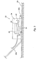
Fig. 2 is a schematic side view showing one finger assembly of the pig ofFig. 1 ; -
Fig. 3 is a schematic cross-section of part of the finger ofFig. 2 to an enlarged scale; -
Fig. 4 shows one form of electronics in the pig of the present invention; -
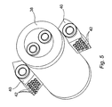
Fig. 5 shows part of an exemplary pig in greater detail; -
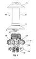
Fig. 6 is a side view of a pipeline pig forming a second embodiment of the invention; and -
Fig. 7 is a side view showing part of the pig ofFig. 6 in greater detail, to an enlarged scale. - Referring to
Fig. 1 , a pipeline pig comprises a metal body ormandrel 10.Resilient cups 12 typically of polyurethane are clamped to and extend from thebody 10 for engagement with the inner wall of a pipeline such that the pig is transported through the pipeline by product pressure and flow rate. Ahub 14 extends rearwardly of thebody 10 and mounts threeequispaced arms 16 each carrying awheel 18, thearms 16 being biased outwardly to engage thewheels 18 with the pipeline wall. Thewheels 18 drive rotary sensors (not shown) to provide odometer information. As an alternative, two or four odometer wheels could be used. The pig as thus far described is known per se. - The pig is also provided with an annular ring of
resilient fingers 20 each of which has an outwardly extendingportion 20a and an outeraxial portion 20b. Thefingers 20 could be, for example, integral spring steel fingers. Alternatively, rigid fingers hinged to thebody 10 and biased by springs or the like could be used. In typical embodiments, thefingers 20 are about 30mm wide, giving a total of 25 fingers for a 10 inch pipeline, increasing proportionately up to 110 fingers for a 42 inch pipeline, and so on for greater diameters. In general terms, it is preferred to use as great a number of detectors as can be accommodated for maximum resolution. - As seen in
Figs. 2 and3 , each of thefingers 20 carries within itsaxial portion 20b asensor assembly 22. Eachsensor assembly 22 is therefore drawn along the pipeline in a fixed relation to theinner surface 28 of the pipeline, i.e. the inner surface provided by the pipe itself or by any debris attached to the pipe wall. It will be appreciated that thefingers 20 can flex independently of each other, and thus eachsensor assembly 22 monitors a small part of the circumference independently of the other parts. - The
sensor assembly 22 comprises aHall effect sensor 24 and amagnet 26 spaced apart by a distance d1 and with thesensor 24 at a distance d2 from theinternal surface 28 of the pipeline. This can conveniently be arranged by mounting theHall effect sensor 24 on a printedcircuit board 30, and mounting themagnet 26 to thepcb 30 via aspacer 32, all these parts then being encapsulated in ablock 34 of polyurethane or other suitable resin. - The
magnet 26 may suitably be a NdFeB material; for use in typical oil pipeline applications a high temperature grade capable of operating to 150°C should be chosen. However, any other suitable magnetic material can be used, for example samarium cobalt. Examples of suitable forms of Hall effect sensor are Allegro 1032 and Honeywell SS 495. - We have established that a particularly suitable arrangement is to have the
sensor 24 as close as possible to the wall with d2 about 2 to 3 mm, and to have themagnet 26 arranged to produce radial flux and with d1 about 10 to 12 mm. A suitable size of magnet is 10 x 10 mm, and a suitable size of Hall effect sensor is 2 x 2 mm. This gives a sensitivity which gives a useful range of Hall effect output for a lift-off of the sensor caused by debris from zero to about 20mm, which is the range likely to be found in practice. We have established that the accuracy of the measurements can be less than 1 mm. - Other arrangements are possible but less preferred. For example, it would be possible to use axial flux, but this is likely to be less sensitive. It would also be possible to use magnetic sensors other than Hall effect, for example magnetoresistors or induction coils; however, implementing these would be more complex, especially in pipeline conditions of high pressure and high temperature, and sensitivity is likely to be poorer.
- Referring to
Fig. 4 , typically the outputs of thevarious sensors 24 are supplied to amemory 36 within the pig, together with odometer readings, such that the condition of the pipeline can be analysed after the pig traverse by downloading thememory 36. - In a preferred arrangement, the
memory 36 and associated control and power supply circuits are contained with a pressure vessel 38 (Fig. 5 ) forming part of thepig body 10, and the sensor signals are multiplexed to thememory 36 bymultiplexers 44 contained within a pair ofmultiplexer boxes 40 secured to thepressure vessel 38. Themultiplexer boxes 40 are provided withcable glands 42, one per sensor and are potted with epoxy resin once the cables have been connected, and are connected to thememory 36 via single entries underlying theboxes 40. This arrangement reduces the access requirements to the pressure vessel. - The use of a pressure vessel is particularly beneficial in manufacturing the vehicle to ATEX standards, since high power parts of the system, such as batteries, can be contained within a flameproof enclosure.
- The
multiplexers 44 may be arranged to sample the sensors on the basis of either distance or time. Distance sampling is preferred, with sampling occurring every 5 mm or so. - The
odometer wheels 18 conventionally use Hall effect rotation sensors, and these can also be multiplexed via one or both of theboxes 40. - The pig may also incorporate other sensors (not shown). For example, an axial vibration sensor (which may typically be sensitive to axial accelerations of ± 10g) can be used to indicate areas where the internal surface of the pipeline is uneven, and a differential pressure sensor (which may typically be sensitive to differential pressures of ± 10bar) can be used to identify changes in pipeline bore. It may also be useful to include a temperature sensor.
-
Figs. 6 and7 show another embodiment of the present invention. In these Figures parts which are similar to the first embodiment are denoted by like reference numerals and will not be further described. - In this embodiment, the body of the pig is in two
parts leading part 10a comprises apressure vessel 38 and propellingcups 12. The trailingpart 10b carries a finger assembly generally designated at 120, which will be described in detail below, and an odometerassembly comprising wheels 18 biased outwardly by springs 50. - The use of a two-part articulated form is particularly suitable for use in narrow bore pipes, for example 10 and 12 inch, where a one-piece pig might have difficulty in traversing bends. In long runs with tight bends it may be desirable to use an articulated pig with three (or more) parts.
- The
finger assembly 120 as in the previous embodiment comprises a complete ring of outwardly-biased fingers each of which carries a magnetic proximity sensor assembly. In this embodiment however each finger, as best seen inFig. 7 , is formed by threerigid segments first segment 120a is secured to the trailingbody part 10b. Thesecond segment 120b is hinged to thefirst segment 120a by means of ahinge pin 52. Thesecond segment 120b andthird segment 120c are interconnected by afibre hinge 54. Each finger is biased outwardly by means of a C-shaped polyurethane body 56 (seeFig. 6 ) having one end engaged in achannel 58 of thethird finger segment 120c and the other end engaged in a similar formation in thebody portion 10b. - The sensor assembly comprises a
Hall effect sensor 24 and apermanent magnet 26. The associated processing circuitry is provided on apcb 60 which is carried on theintermediate finger portion 120b, and is connected to aconnector 62 within thefirst finger segment 120a, which is of channel section. In this embodiment, themagnet 26 is carried on theouter segment 120c, while the Hall effect sensor is on theintermediate segment 120b. The spatial relationship is thus different to that of the first embodiment. However, the particular components used may be as in the first embodiment. Themagnet 26 andpcb 60 may suitably be encapsulated in resin, for example epoxy or polyurethane. - In this embodiment, each sensor assembly has its own multiplexer on the associated
pcb 60. As in the first embodiment, the remaining electronics and power storage are housed within thepressure vessel 38. This arrangement minimises the amount of cabling between the two body portions. - The present embodiment is also capable of performing calliper (i.e. inside diameter) measurements. For this purpose, each finger is provided with means to measure the angular position of the
intermediate finger segment 120b with respect to the fixedfirst finger segment 120a. In the present example, this is by means of aHall effect sensor 64 located adjacent thehinge pin 52. Other forms of angle detection may be used, for example linear displacement voltage transducers, magnetic sliders, or strain gauges. - This approach to calliper measurement is known per se. However, the present invention makes possible the use of calliper measurement in conjunction with detection of surface contamination simultaneously in a manner which allows the combination of pipeline wall wastage and fouling to be determined, which was not previously possible.
- Modifications may be made to the foregoing embodiments within the scope of the invention. The vehicle may be self-propelled from an internal power source or via an umbilical, rather than a pig. Where the vehicle is a pig, it is possible to use one cup rather than two, or to use wall-engaging members other than resilient cups. The flexible fingers may be positioned differently in relation to the driving cups or equivalent; in particular in some uses it is desirable to use a one-piece pig with two driving cups, but with the fingers at the trailing end of the pig, rather than between the cups.
- Further sensors may also be mounted on the vehicle, for example known sensors for identifying pipeline furniture such as valves and T-pieces.
- The invention thus provides a pipeline pig which is capable of detecting and measuring the thickness of debris independently at numerous locations around the circumference, and distinguishing debris from variations in cross-section caused by corrosion or deformation of the pipe wall.
Claims (15)
- A pipeline inspection vehicle comprising:a body (10);propulsion means for driving the body (10) through a pipeline; andat least one finger (20) extending from the body (10) and resiliently movable in a radial direction to engage with the wall of the pipeline;the finger (20) carrying adjacent its wall-engaging portion a magnetic proximity sensor assembly (22) comprising a permanent magnet (26) arranged to produce a radial flux and a magnetic sensor (24);characterised in that the sensor (24) is spaced a radial distance (d1) from the magnet (26) on the side of the magnet (26) opposed to the body (10), and the sensor (24) provides an output signal which is a function of the spacing between the sensor (24) and metal of the pipeline wall.
- A vehicle according to claim 1, in which a plurality of said fingers (20) extend from the body (10), the fingers (20) being independently resiliently movable in the radial direction.
- A vehicle according to claim 2, in which said fingers (20) form a substantially continuous ring around the body (10).
- A vehicle according to claim 3, in which there are from 25 to 110 fingers (20) for pipelines ranging from 10 inches to 42 inches diameter.
- A vehicle according to any preceding claim, in which the vehicle is a pig, and includes one or more cups or discs (12) extending from the body (10) for engagement with the wall of the pipeline to drive the pig therethrough by product pressure and flow.
- A vehicle according to any preceding claim, in which the magnetic sensor (24) comprises a Hall effect sensor.
- A vehicle according to any preceding claim, including memory means (36) for storing said output signals as the vehicle traverses a pipeline.
- A vehicle according to claim 7, in which the sensors (24) are interfaced with the memory means (36) through one or more multiplexers (44).
- A vehicle according to claim 8, in which the memory means (36) and associated circuits are contained within a pressure vessel (38), and the one or more multiplexers (44) are arranged externally of the pressure vessel (38).
- A vehicle according to claim 9, in which the body (10) is in two parts which are articulated together, and wherein one part of the body (10) comprises the pressure vessel (38) and the other part comprises the finger or fingers (20).
- A vehicle according to claim 3, including means for measuring the angular deflection of the fingers (20) to provide a measure of interior diameter.
- A vehicle according to any preceding claim, including distance measuring means (18).
- A method of monitoring debris in a pipeline, comprising traversing at least one magnetic proximity sensor assembly (22) along the pipeline in physical contact with the internal surface of the pipeline, the sensor assembly (22) comprising a permanent magnet (26) arranged to produce a radial flux and a magnetic sensor (24);
characterised in that the sensor (24) is spaced a radial distance (d1) from the magnet (26) on the side of the magnet (26) opposed to the body (10), whereby debris attached to the pipeline wall may be detected by a decreased proximity signal which is a function of the spacing between the sensor (24) and metal of the pipeline wall. - The method of claim 13, in which an annular array of such sensor assemblies (22) is traversed to examine the circumference in one pass.
- The method of claim 13, including also measuring the internal diameter of the pipeline by measuring angular deflection of the fingers (20).
Applications Claiming Priority (2)
| Application Number | Priority Date | Filing Date | Title |
|---|---|---|---|
| GBGB0807940.2A GB0807940D0 (en) | 2008-05-01 | 2008-05-01 | Pipeline monitoring apparatus and method |
| PCT/GB2009/050452 WO2009133404A1 (en) | 2008-05-01 | 2009-05-01 | Pipeline monitoring apparatus and method |
Publications (2)
| Publication Number | Publication Date |
|---|---|
| EP2288838A1 EP2288838A1 (en) | 2011-03-02 |
| EP2288838B1 true EP2288838B1 (en) | 2014-02-26 |
Family
ID=39537120
Family Applications (1)
| Application Number | Title | Priority Date | Filing Date |
|---|---|---|---|
| EP09738434.1A Active EP2288838B1 (en) | 2008-05-01 | 2009-05-01 | Pipeline monitoring apparatus and method |
Country Status (5)
| Country | Link |
|---|---|
| US (1) | US20110095752A1 (en) |
| EP (1) | EP2288838B1 (en) |
| DK (1) | DK2288838T3 (en) |
| GB (1) | GB0807940D0 (en) |
| WO (1) | WO2009133404A1 (en) |
Families Citing this family (24)
| Publication number | Priority date | Publication date | Assignee | Title |
|---|---|---|---|---|
| EP2474770A1 (en) * | 2011-01-11 | 2012-07-11 | PII Limited | Apparatus for pipeline inspection |
| ITMI20112239A1 (en) | 2011-12-12 | 2013-06-13 | Eni Spa | "PIPELINE INSPECTION GAUGE FOR INTERNAL INSPECTION OF CONDUCT" |
| DE102012009347A1 (en) * | 2012-05-09 | 2013-11-14 | Eisenmann Ag | System for detecting a cross-sectional profile |
| US9222896B2 (en) * | 2012-09-14 | 2015-12-29 | Halliburton Energy Services, Inc. | Systems and methods for inspecting and monitoring a pipeline |
| US20140080223A1 (en) * | 2012-09-14 | 2014-03-20 | Halliburton Energy Services, Inc. | Systems and Methods for Inspecting and Monitoring a Pipeline |
| US9176052B2 (en) * | 2012-09-14 | 2015-11-03 | Halliburton Energy Services, Inc. | Systems and methods for inspecting and monitoring a pipeline |
| US8765061B2 (en) * | 2012-09-14 | 2014-07-01 | Halliburton Energy Services, Inc. | Systems and methods for inspecting and monitoring a pipeline |
| US9483055B2 (en) | 2012-12-28 | 2016-11-01 | Irobot Corporation | Autonomous coverage robot |
| CA2914772C (en) * | 2013-06-12 | 2019-02-26 | Vretmaskin El & Mekanik Ab | Pipe inspection device |
| MC200156B1 (en) * | 2013-07-30 | 2014-02-19 | 3X Eng | Improved reinforcement tape for the repair of fluid transport pipelines |
| DE102014001001A1 (en) * | 2014-01-29 | 2015-07-30 | Rosen Swiss Ag | Newt and piglet for a newt |
| US9662690B2 (en) | 2014-07-15 | 2017-05-30 | Chevron U.S.A. Inc. | Systems for maintaining a functional line for conveying fluid and pig assemblies for use therein |
| WO2017197505A1 (en) * | 2016-05-20 | 2017-11-23 | Desjardins Integrity Ltd. | System and method for detecting and characterizing defects in a pipe |
| US10458822B2 (en) * | 2016-07-11 | 2019-10-29 | Entegra LLP | Dynamic spacer for a smart pipeline inspection gauge |
| CN109001294B (en) * | 2017-06-06 | 2024-01-30 | 中国石油天然气股份有限公司 | Pipeline inner wall detection device |
| CA3108804A1 (en) * | 2018-08-08 | 2020-02-13 | Pure Technologies Ltd. | Method and apparatus to detect flaws in metallic pipe |
| CN109269397A (en) * | 2018-10-26 | 2019-01-25 | 同人拓丰(北京)科技有限公司 | A kind of ultromotivity device with pipeline geometry deformation detection function |
| CN109506077B (en) * | 2018-12-21 | 2020-06-16 | 苏州经贸职业技术学院 | A PCCP Pipeline Broken Wire Detection Device for Underwater Condition |
| CN111664784B (en) * | 2019-03-09 | 2022-02-01 | 中国石油天然气股份有限公司 | Device and method for determining deformation position of pipeline |
| ES2976777T3 (en) | 2020-04-22 | 2024-08-08 | Indian Oil Corp Ltd | A calibration scraper for detecting geometric deformation of a pipe |
| CN111974768B (en) * | 2020-08-04 | 2024-02-02 | 中冶北方(大连)工程技术有限公司 | Scraper and quick assembly device and method thereof |
| CN112762276B (en) * | 2021-01-31 | 2025-06-03 | 中国船舶重工集团公司七五0试验场 | Pipeline inspection pig and method capable of marking residual attachments on inner wall of pipeline |
| US20240384825A1 (en) | 2021-10-01 | 2024-11-21 | Pipeway Engenharia Ltda | Internal duct integrity inspection equipment using magnetic metal memory |
| CN114646250B (en) * | 2022-05-18 | 2022-08-05 | 东北大学 | High-trafficability pipeline reducing detection and positioning device |
Family Cites Families (12)
| Publication number | Priority date | Publication date | Assignee | Title |
|---|---|---|---|---|
| US3974680A (en) * | 1975-05-27 | 1976-08-17 | Inspection Technology Development, Inc. | Pipeline leak detector |
| US5293117A (en) * | 1992-05-14 | 1994-03-08 | Western Atlas International, Inc. | Magnetic flaw detector for use with ferromagnetic small diameter tubular goods using a second magnetic field to confine a first magnetic field |
| WO1996013699A2 (en) * | 1994-10-27 | 1996-05-09 | I.D. Measurements, Inc. | Pipeline inspection pig and method for using same |
| US6076407A (en) * | 1998-05-15 | 2000-06-20 | Framatome Technologies, Inc. | Pipe inspection probe |
| CA2361813A1 (en) * | 2001-01-29 | 2002-07-29 | Peter O. Paulson | Low frequency electromagnetic analysis of prestressed concrete tensioning strands |
| US7038444B2 (en) * | 2003-03-19 | 2006-05-02 | Southwest Research Institute | System and method for in-line stress measurement by continuous Barkhausen method |
| GB2401130B (en) * | 2003-04-30 | 2006-11-01 | Weatherford Lamb | A traction apparatus |
| NZ529182A (en) * | 2003-12-20 | 2007-02-23 | Colin Brian Nicholson | Self-propelled vehicle for use in a conduit |
| US20050223825A1 (en) * | 2004-01-16 | 2005-10-13 | Theo Janssen | Method to prevent rotation of caliper tools and other pipeline tools |
| US6847207B1 (en) * | 2004-04-15 | 2005-01-25 | Tdw Delaware, Inc. | ID-OD discrimination sensor concept for a magnetic flux leakage inspection tool |
| US7256576B2 (en) * | 2005-07-29 | 2007-08-14 | General Electric Company | ID-OD discrimination sensor |
| US7683611B2 (en) * | 2006-06-23 | 2010-03-23 | Southwest Research Institute | Pipeline inspection using variable-diameter remote-field eddy current technology |
-
2008
- 2008-05-01 GB GBGB0807940.2A patent/GB0807940D0/en not_active Ceased
-
2009
- 2009-05-01 EP EP09738434.1A patent/EP2288838B1/en active Active
- 2009-05-01 DK DK09738434.1T patent/DK2288838T3/en active
- 2009-05-01 US US12/989,182 patent/US20110095752A1/en not_active Abandoned
- 2009-05-01 WO PCT/GB2009/050452 patent/WO2009133404A1/en not_active Ceased
Also Published As
| Publication number | Publication date |
|---|---|
| DK2288838T3 (en) | 2014-06-02 |
| US20110095752A1 (en) | 2011-04-28 |
| WO2009133404A1 (en) | 2009-11-05 |
| GB0807940D0 (en) | 2008-06-11 |
| EP2288838A1 (en) | 2011-03-02 |
Similar Documents
| Publication | Publication Date | Title |
|---|---|---|
| US20110095752A1 (en) | Pipeline monitoring apparatus and method | |
| CA1284027C (en) | Electronic kaliper system | |
| US5864232A (en) | Magnetic flux pipe inspection apparatus for analyzing anomalies in a pipeline wall | |
| AU762224B2 (en) | Device for inspecting water pipelines and method | |
| EP2100072B1 (en) | Linear structure inspection apparatus and method | |
| KR101491416B1 (en) | Magnetic Flux Leakage Pig | |
| RU2176082C1 (en) | Intrapipe magnetic flaw detector | |
| EP4411365A1 (en) | Internal duct integrity inspection equipment using magnetic metal memory | |
| US20100308809A1 (en) | Pipeline geometry sensor | |
| JPH0814574B2 (en) | Pipeline inspection equipment | |
| CN101936950B (en) | Pipeline inspection tool with oblique magnetizer | |
| US20050223825A1 (en) | Method to prevent rotation of caliper tools and other pipeline tools | |
| WO2007020438A2 (en) | Pig for inspecting pipelines internally | |
| US10458822B2 (en) | Dynamic spacer for a smart pipeline inspection gauge | |
| CA1081941A (en) | Probing device for the interior of pipelines | |
| CA2443217A1 (en) | Method and apparatus for measuring the inner diameter of pipeline | |
| KR20060105253A (en) | Pipe diameter measuring device and pipe deformation measuring device equipped with the same | |
| RU2164661C1 (en) | Intertubular multi-channel profilometer | |
| US4628613A (en) | Bend detector for a pipeline pig | |
| CS209709B1 (en) | Apparatus for internal inspection of long-distance pipelines | |
| RU2176081C1 (en) | Magnetic going-through flaw detector | |
| GB2285510A (en) | Detection apparatus for use with a cylindrical member | |
| JP3791889B2 (en) | In-pipe inspection device | |
| EP0999428A1 (en) | Pipeline inspection device | |
| CA2757488C (en) | Linear structure inspection apparatus and method |
Legal Events
| Date | Code | Title | Description |
|---|---|---|---|
| PUAI | Public reference made under article 153(3) epc to a published international application that has entered the european phase |
Free format text: ORIGINAL CODE: 0009012 |
|
| 17P | Request for examination filed |
Effective date: 20100924 |
|
| AK | Designated contracting states |
Kind code of ref document: A1 Designated state(s): AT BE BG CH CY CZ DE DK EE ES FI FR GB GR HR HU IE IS IT LI LT LU LV MC MK MT NL NO PL PT RO SE SI SK TR |
|
| AX | Request for extension of the european patent |
Extension state: AL BA RS |
|
| DAX | Request for extension of the european patent (deleted) | ||
| 17Q | First examination report despatched |
Effective date: 20120402 |
|
| GRAP | Despatch of communication of intention to grant a patent |
Free format text: ORIGINAL CODE: EPIDOSNIGR1 |
|
| RAP1 | Party data changed (applicant data changed or rights of an application transferred) |
Owner name: PIPELINE ENGINEERING & SUPPLY CO. LTD. |
|
| GRAP | Despatch of communication of intention to grant a patent |
Free format text: ORIGINAL CODE: EPIDOSNIGR1 |
|
| INTG | Intention to grant announced |
Effective date: 20130905 |
|
| GRAS | Grant fee paid |
Free format text: ORIGINAL CODE: EPIDOSNIGR3 |
|
| GRAA | (expected) grant |
Free format text: ORIGINAL CODE: 0009210 |
|
| AK | Designated contracting states |
Kind code of ref document: B1 Designated state(s): AT BE BG CH CY CZ DE DK EE ES FI FR GB GR HR HU IE IS IT LI LT LU LV MC MK MT NL NO PL PT RO SE SI SK TR |
|
| REG | Reference to a national code |
Ref country code: GB Ref legal event code: FG4D |
|
| REG | Reference to a national code |
Ref country code: CH Ref legal event code: EP |
|
| REG | Reference to a national code |
Ref country code: AT Ref legal event code: REF Ref document number: 653823 Country of ref document: AT Kind code of ref document: T Effective date: 20140315 |
|
| REG | Reference to a national code |
Ref country code: IE Ref legal event code: FG4D |
|
| REG | Reference to a national code |
Ref country code: DE Ref legal event code: R096 Ref document number: 602009022014 Country of ref document: DE Effective date: 20140410 |
|
| REG | Reference to a national code |
Ref country code: NL Ref legal event code: T3 |
|
| REG | Reference to a national code |
Ref country code: CH Ref legal event code: NV Representative=s name: MURGITROYD AND COMPANY, CH |
|
| REG | Reference to a national code |
Ref country code: DK Ref legal event code: T3 Effective date: 20140526 |
|
| REG | Reference to a national code |
Ref country code: AT Ref legal event code: MK05 Ref document number: 653823 Country of ref document: AT Kind code of ref document: T Effective date: 20140226 |
|
| REG | Reference to a national code |
Ref country code: NO Ref legal event code: T2 Effective date: 20140226 |
|
| REG | Reference to a national code |
Ref country code: LT Ref legal event code: MG4D |
|
| PG25 | Lapsed in a contracting state [announced via postgrant information from national office to epo] |
Ref country code: LT Free format text: LAPSE BECAUSE OF FAILURE TO SUBMIT A TRANSLATION OF THE DESCRIPTION OR TO PAY THE FEE WITHIN THE PRESCRIBED TIME-LIMIT Effective date: 20140226 Ref country code: IS Free format text: LAPSE BECAUSE OF FAILURE TO SUBMIT A TRANSLATION OF THE DESCRIPTION OR TO PAY THE FEE WITHIN THE PRESCRIBED TIME-LIMIT Effective date: 20140626 |
|
| PG25 | Lapsed in a contracting state [announced via postgrant information from national office to epo] |
Ref country code: AT Free format text: LAPSE BECAUSE OF FAILURE TO SUBMIT A TRANSLATION OF THE DESCRIPTION OR TO PAY THE FEE WITHIN THE PRESCRIBED TIME-LIMIT Effective date: 20140226 Ref country code: FI Free format text: LAPSE BECAUSE OF FAILURE TO SUBMIT A TRANSLATION OF THE DESCRIPTION OR TO PAY THE FEE WITHIN THE PRESCRIBED TIME-LIMIT Effective date: 20140226 Ref country code: CY Free format text: LAPSE BECAUSE OF FAILURE TO SUBMIT A TRANSLATION OF THE DESCRIPTION OR TO PAY THE FEE WITHIN THE PRESCRIBED TIME-LIMIT Effective date: 20140226 Ref country code: PT Free format text: LAPSE BECAUSE OF FAILURE TO SUBMIT A TRANSLATION OF THE DESCRIPTION OR TO PAY THE FEE WITHIN THE PRESCRIBED TIME-LIMIT Effective date: 20140626 Ref country code: SE Free format text: LAPSE BECAUSE OF FAILURE TO SUBMIT A TRANSLATION OF THE DESCRIPTION OR TO PAY THE FEE WITHIN THE PRESCRIBED TIME-LIMIT Effective date: 20140226 |
|
| PG25 | Lapsed in a contracting state [announced via postgrant information from national office to epo] |
Ref country code: BE Free format text: LAPSE BECAUSE OF FAILURE TO SUBMIT A TRANSLATION OF THE DESCRIPTION OR TO PAY THE FEE WITHIN THE PRESCRIBED TIME-LIMIT Effective date: 20140226 Ref country code: HR Free format text: LAPSE BECAUSE OF FAILURE TO SUBMIT A TRANSLATION OF THE DESCRIPTION OR TO PAY THE FEE WITHIN THE PRESCRIBED TIME-LIMIT Effective date: 20140226 Ref country code: LV Free format text: LAPSE BECAUSE OF FAILURE TO SUBMIT A TRANSLATION OF THE DESCRIPTION OR TO PAY THE FEE WITHIN THE PRESCRIBED TIME-LIMIT Effective date: 20140226 |
|
| PG25 | Lapsed in a contracting state [announced via postgrant information from national office to epo] |
Ref country code: RO Free format text: LAPSE BECAUSE OF FAILURE TO SUBMIT A TRANSLATION OF THE DESCRIPTION OR TO PAY THE FEE WITHIN THE PRESCRIBED TIME-LIMIT Effective date: 20140226 Ref country code: EE Free format text: LAPSE BECAUSE OF FAILURE TO SUBMIT A TRANSLATION OF THE DESCRIPTION OR TO PAY THE FEE WITHIN THE PRESCRIBED TIME-LIMIT Effective date: 20140226 Ref country code: CZ Free format text: LAPSE BECAUSE OF FAILURE TO SUBMIT A TRANSLATION OF THE DESCRIPTION OR TO PAY THE FEE WITHIN THE PRESCRIBED TIME-LIMIT Effective date: 20140226 |
|
| REG | Reference to a national code |
Ref country code: DE Ref legal event code: R097 Ref document number: 602009022014 Country of ref document: DE |
|
| PG25 | Lapsed in a contracting state [announced via postgrant information from national office to epo] |
Ref country code: SK Free format text: LAPSE BECAUSE OF FAILURE TO SUBMIT A TRANSLATION OF THE DESCRIPTION OR TO PAY THE FEE WITHIN THE PRESCRIBED TIME-LIMIT Effective date: 20140226 Ref country code: PL Free format text: LAPSE BECAUSE OF FAILURE TO SUBMIT A TRANSLATION OF THE DESCRIPTION OR TO PAY THE FEE WITHIN THE PRESCRIBED TIME-LIMIT Effective date: 20140226 Ref country code: ES Free format text: LAPSE BECAUSE OF FAILURE TO SUBMIT A TRANSLATION OF THE DESCRIPTION OR TO PAY THE FEE WITHIN THE PRESCRIBED TIME-LIMIT Effective date: 20140226 |
|
| PG25 | Lapsed in a contracting state [announced via postgrant information from national office to epo] |
Ref country code: LU Free format text: LAPSE BECAUSE OF FAILURE TO SUBMIT A TRANSLATION OF THE DESCRIPTION OR TO PAY THE FEE WITHIN THE PRESCRIBED TIME-LIMIT Effective date: 20140501 |
|
| PLBE | No opposition filed within time limit |
Free format text: ORIGINAL CODE: 0009261 |
|
| STAA | Information on the status of an ep patent application or granted ep patent |
Free format text: STATUS: NO OPPOSITION FILED WITHIN TIME LIMIT |
|
| PG25 | Lapsed in a contracting state [announced via postgrant information from national office to epo] |
Ref country code: MC Free format text: LAPSE BECAUSE OF FAILURE TO SUBMIT A TRANSLATION OF THE DESCRIPTION OR TO PAY THE FEE WITHIN THE PRESCRIBED TIME-LIMIT Effective date: 20140226 |
|
| 26N | No opposition filed |
Effective date: 20141127 |
|
| REG | Reference to a national code |
Ref country code: IE Ref legal event code: MM4A |
|
| REG | Reference to a national code |
Ref country code: DE Ref legal event code: R097 Ref document number: 602009022014 Country of ref document: DE Effective date: 20141127 |
|
| PG25 | Lapsed in a contracting state [announced via postgrant information from national office to epo] |
Ref country code: IT Free format text: LAPSE BECAUSE OF FAILURE TO SUBMIT A TRANSLATION OF THE DESCRIPTION OR TO PAY THE FEE WITHIN THE PRESCRIBED TIME-LIMIT Effective date: 20140226 |
|
| PG25 | Lapsed in a contracting state [announced via postgrant information from national office to epo] |
Ref country code: IE Free format text: LAPSE BECAUSE OF NON-PAYMENT OF DUE FEES Effective date: 20140501 |
|
| PG25 | Lapsed in a contracting state [announced via postgrant information from national office to epo] |
Ref country code: SI Free format text: LAPSE BECAUSE OF FAILURE TO SUBMIT A TRANSLATION OF THE DESCRIPTION OR TO PAY THE FEE WITHIN THE PRESCRIBED TIME-LIMIT Effective date: 20140226 |
|
| PG25 | Lapsed in a contracting state [announced via postgrant information from national office to epo] |
Ref country code: MT Free format text: LAPSE BECAUSE OF FAILURE TO SUBMIT A TRANSLATION OF THE DESCRIPTION OR TO PAY THE FEE WITHIN THE PRESCRIBED TIME-LIMIT Effective date: 20140226 |
|
| REG | Reference to a national code |
Ref country code: FR Ref legal event code: PLFP Year of fee payment: 8 |
|
| PG25 | Lapsed in a contracting state [announced via postgrant information from national office to epo] |
Ref country code: BG Free format text: LAPSE BECAUSE OF FAILURE TO SUBMIT A TRANSLATION OF THE DESCRIPTION OR TO PAY THE FEE WITHIN THE PRESCRIBED TIME-LIMIT Effective date: 20140226 Ref country code: GR Free format text: LAPSE BECAUSE OF FAILURE TO SUBMIT A TRANSLATION OF THE DESCRIPTION OR TO PAY THE FEE WITHIN THE PRESCRIBED TIME-LIMIT Effective date: 20140527 |
|
| PGFP | Annual fee paid to national office [announced via postgrant information from national office to epo] |
Ref country code: NL Payment date: 20160524 Year of fee payment: 8 |
|
| PG25 | Lapsed in a contracting state [announced via postgrant information from national office to epo] |
Ref country code: TR Free format text: LAPSE BECAUSE OF FAILURE TO SUBMIT A TRANSLATION OF THE DESCRIPTION OR TO PAY THE FEE WITHIN THE PRESCRIBED TIME-LIMIT Effective date: 20140226 Ref country code: HU Free format text: LAPSE BECAUSE OF FAILURE TO SUBMIT A TRANSLATION OF THE DESCRIPTION OR TO PAY THE FEE WITHIN THE PRESCRIBED TIME-LIMIT; INVALID AB INITIO Effective date: 20090501 |
|
| PGFP | Annual fee paid to national office [announced via postgrant information from national office to epo] |
Ref country code: CH Payment date: 20160519 Year of fee payment: 8 Ref country code: DE Payment date: 20160518 Year of fee payment: 8 |
|
| PGFP | Annual fee paid to national office [announced via postgrant information from national office to epo] |
Ref country code: DK Payment date: 20160520 Year of fee payment: 8 |
|
| REG | Reference to a national code |
Ref country code: FR Ref legal event code: PLFP Year of fee payment: 9 |
|
| REG | Reference to a national code |
Ref country code: DE Ref legal event code: R119 Ref document number: 602009022014 Country of ref document: DE |
|
| REG | Reference to a national code |
Ref country code: CH Ref legal event code: PL |
|
| REG | Reference to a national code |
Ref country code: DK Ref legal event code: EBP Effective date: 20170531 |
|
| REG | Reference to a national code |
Ref country code: NL Ref legal event code: MM Effective date: 20170601 |
|
| PG25 | Lapsed in a contracting state [announced via postgrant information from national office to epo] |
Ref country code: LI Free format text: LAPSE BECAUSE OF NON-PAYMENT OF DUE FEES Effective date: 20170531 Ref country code: CH Free format text: LAPSE BECAUSE OF NON-PAYMENT OF DUE FEES Effective date: 20170531 |
|
| PG25 | Lapsed in a contracting state [announced via postgrant information from national office to epo] |
Ref country code: NL Free format text: LAPSE BECAUSE OF NON-PAYMENT OF DUE FEES Effective date: 20170601 |
|
| PG25 | Lapsed in a contracting state [announced via postgrant information from national office to epo] |
Ref country code: DE Free format text: LAPSE BECAUSE OF NON-PAYMENT OF DUE FEES Effective date: 20171201 Ref country code: DK Free format text: LAPSE BECAUSE OF NON-PAYMENT OF DUE FEES Effective date: 20170531 |
|
| REG | Reference to a national code |
Ref country code: FR Ref legal event code: PLFP Year of fee payment: 10 |
|
| PG25 | Lapsed in a contracting state [announced via postgrant information from national office to epo] |
Ref country code: MK Free format text: LAPSE BECAUSE OF FAILURE TO SUBMIT A TRANSLATION OF THE DESCRIPTION OR TO PAY THE FEE WITHIN THE PRESCRIBED TIME-LIMIT Effective date: 20140226 |
|
| REG | Reference to a national code |
Ref country code: NO Ref legal event code: CREP Representative=s name: PROTECTOR IP AS, PILESTREDET 33, 0166 OSLO, NORGE Ref country code: NO Ref legal event code: CHAD Owner name: PIPELINES 2 DATA (P2D) LIMITED, GB |
|
| REG | Reference to a national code |
Ref country code: GB Ref legal event code: 732E Free format text: REGISTERED BETWEEN 20220623 AND 20220629 |
|
| PGFP | Annual fee paid to national office [announced via postgrant information from national office to epo] |
Ref country code: NO Payment date: 20250402 Year of fee payment: 17 |
|
| PGFP | Annual fee paid to national office [announced via postgrant information from national office to epo] |
Ref country code: FR Payment date: 20250415 Year of fee payment: 17 |
|
| PGFP | Annual fee paid to national office [announced via postgrant information from national office to epo] |
Ref country code: GB Payment date: 20260327 Year of fee payment: 18 |