EP2287648A2 - Optical system and optical apparatus having the same - Google Patents
Optical system and optical apparatus having the same Download PDFInfo
- Publication number
- EP2287648A2 EP2287648A2 EP10171595A EP10171595A EP2287648A2 EP 2287648 A2 EP2287648 A2 EP 2287648A2 EP 10171595 A EP10171595 A EP 10171595A EP 10171595 A EP10171595 A EP 10171595A EP 2287648 A2 EP2287648 A2 EP 2287648A2
- Authority
- EP
- European Patent Office
- Prior art keywords
- lens
- optical system
- θgf
- conjugate side
- negative lens
- Prior art date
- Legal status (The legal status is an assumption and is not a legal conclusion. Google has not performed a legal analysis and makes no representation as to the accuracy of the status listed.)
- Granted
Links
Images



Classifications
-
- G—PHYSICS
- G02—OPTICS
- G02B—OPTICAL ELEMENTS, SYSTEMS OR APPARATUS
- G02B13/00—Optical objectives specially designed for the purposes specified below
- G02B13/04—Reversed telephoto objectives
-
- G—PHYSICS
- G02—OPTICS
- G02B—OPTICAL ELEMENTS, SYSTEMS OR APPARATUS
- G02B13/00—Optical objectives specially designed for the purposes specified below
- G02B13/16—Optical objectives specially designed for the purposes specified below for use in conjunction with image converters or intensifiers, or for use with projectors, e.g. objectives for projection TV
-
- G—PHYSICS
- G02—OPTICS
- G02B—OPTICAL ELEMENTS, SYSTEMS OR APPARATUS
- G02B27/00—Optical systems or apparatus not provided for by any of the groups G02B1/00 - G02B26/00, G02B30/00
- G02B27/0025—Optical systems or apparatus not provided for by any of the groups G02B1/00 - G02B26/00, G02B30/00 for optical correction, e.g. distorsion, aberration
- G02B27/005—Optical systems or apparatus not provided for by any of the groups G02B1/00 - G02B26/00, G02B30/00 for optical correction, e.g. distorsion, aberration for correction of secondary colour or higher-order chromatic aberrations
- G02B27/0062—Optical systems or apparatus not provided for by any of the groups G02B1/00 - G02B26/00, G02B30/00 for optical correction, e.g. distorsion, aberration for correction of secondary colour or higher-order chromatic aberrations by controlling the dispersion of a lens material, e.g. adapting the relative partial dispersion
Definitions
- the present invention relates to an optical system, and is suitable, for example, for a projection optical system configured project image information onto a predetermined surface for a liquid crystal projector or an image pickup optical system of a camera.
- An optical system for a liquid crystal projector is demanded to be a high angle-of-view projection optical system configured to project a high definition image on a large screen with a small distance.
- An optical system for an image pickup apparatus such as a camera, is demanded to be an image pickup optical system having a long back focal length, a high image quality, and a high angle of view configured to shoot a wide subject range.
- a color shift (or chromatic aberration) mitigation among a variety of aberrations of an optical system is important.
- using a lens made of anomalous dispersion glass is effective to correct the chromatic aberration while maintaining a size of the entire optical system.
- U.S. Patent Publication Application No. 2002/0005994 proposes a retrofocus type optical system configured to correct a chromatic aberration using a lens made of anomalous dispersion glass.
- a lens made of an optical material of the anomalous dispersion for the optical path has a difficultly in obtaining a good performance over a screen while well correcting the chromatic aberration.
- the present invention in its first aspect provides an optical system as specified in claims 1-6.
- the present invention in its second aspect provides an optical apparatus as specified in claim 7.
- FIG. 1 is a lens sectional view of a first embodiment.
- FIG. 2 shows a variety of aberrations and a chromatic difference of magnification diagram of the first embodiment.
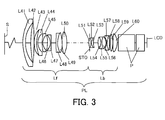
- FIG. 3 is a lens sectional view of a second embodiment.
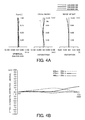
- FIG. 4 shows a variety of aberrations and a chromatic difference of magnification diagram of the second embodiment.
- FIG. 5 is a lens sectional view of a third embodiment.
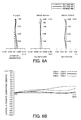
- FIG. 6 shows a variety of aberrations and a chromatic difference of magnification diagram of the third embodiment.
- the optical system of the present invention is an optical system having a single focal length or a zoom lens having a zooming operation, which includes, in order from an enlargement conjugate side to a reduction conjugate side, a front unit having a negative power, and a rear unit having a positive power.
- FIG. 1 is a schematic principal diagram of a first embodiment when the optical system of the present invention is used for a projection optical system for an image projector.
- FIGs. 2A and 2B are a lateral aberration diagram and a chromatic difference of magnification (lateral chromatic aberration) diagram where a distance to a screen (or a distance from a first lens surface) is 1050 [mm] in the first embodiment.
- FIG. 2A is a lateral aberration diagram that represents a spherical aberration, an astigmatism, and a distortion.
- a dotted line, a solid line, and a broken line in the spherical aberration represent aberrations for wavelengths of 620 nm, 550 nm, and 450 nm, respectively.
- FIG. 2B is a lateral aberration diagram of a chromatic difference of magnification, where an abscissa axis denotes an axis perpendicular to the optical axis.
- the chromatic difference of magnification is based on 550 nm, and a broken line, a solid line, and a dotted line represent aberrations for wavelengths of 620 nm, 470 nm, and 440 nm, respectively.
- the aberrational diagrams illustrated in FIGs. 2 , 4 , and 6 are aberrational diagrams when a liquid crystal display (LCD) is located at a position that provides a maximum MTF for a wavelength of 550 nm.
- LCD liquid crystal display
- FIG. 3 is a schematic principal view of a second embodiment when the optical system of the present invention is used for a projection optical system for an image projector.
- FIGs. 4A and 4B are a lateral aberration diagram and a chromatic difference of magnification diagram when a distance to the screen (distance from the first lens surface) is 1050 [mm] in the second embodiment.
- FIG. 5 is a schematic principal view of a third embodiment when the optical system according to the present invention is used for a projection optical system for an image projector.
- FIGS. 6A and 6B are a lateral aberration diagram and a chromatic difference of magnification diagram when a distance to the screen (distance from the first lens surface) is 1210 [mm] in the third embodiment.
- an original image (projected image) to be displayed on a LCD panel is enlarged and projected on a screen surface S using an optical system (projection lens) PL.
- S denotes a screen surface (projection surface)
- LCD is a liquid crystal display panel or device, located on an image plane of the optical system PL.
- the screen surface S and the LCD panel have a conjugate relationship with each other.
- the screen surface S When a distance from the object side principal plane to a conjugates point is compared with a distance from the image side principal plane to the conjugate point, the screen surface S generally corresponds to the conjugate point of a longer distance on the enlargement side (front side or enlargement conjugate side).
- the LCD panel corresponds to the conjugate point of a shorter distance backside or reduction conjugate side).
- the screen S surface side corresponds to the object side
- the LCD panel corresponds to the image side (IP).
- the optical system PL of the first or second embodiments in FIG. 1 or 3 is a so-called retrofocus type having a single focal length, and includes a front unit Lf having a negative power, and a rear unit Lb having a positive power.
- a symbol Lij represents each lens.
- STO denotes a stop.
- a lens holder frame configured to hold a lens serves as the stop STO, but may be provided separate from it.
- P denotes a color separation prism, color synthesis prism, a polarization filter, a color filter, etc., and it is a glass block provided for purposes of the optical design.
- the optical system PL is installed in the image projector body (not illustrated) via a connector (not illustrated).
- the glass block is included in a projector body on the LCD panel side after the glass block P.
- the optical system PL of the third embodiment in FIG. 5 is a zoom lens.
- the optical system PL of the third embodiment includes a front unit Lf having a negative power and a rear unit Lb having a positive power.
- a symbol Gi denotes an i-th lens unit.
- the front unti Lf includes, in order from an enlargement conjugate side to a reduction conjugate side, a first lens unit G1 having a negative power, a second lens unit G2 having a negative power, and a third lens unit G3 having a positive power.
- the rear unit Lb includes a fourth lens unit G4 having a negative power, a fifth lens unit G5 having a positive power, and a sixth lens unit G6 having a positive power.
- the optical system PL of this embodiment is a retrofocus type six-unit zoom lens in which a first lens unit G1 to a fifth lens unit G5 are moved on the optical axis in zooming.
- STO in FIG. 5 denotes a stop.
- a lens holder frame configured to hold a lens serves as the stop STO, but may be provided separate from it.
- P denotes a color separation prism, color synthesis prism, a polarization filter, a color filter, etc., and it is a glass block provided on the optical design.
- the optical system PL is installed in the image projector body (not illustrated) via a connector (not illustrated).
- the glass block is included in a projector body on the LCD panel side after the glass block P.
- At least one negative lens L n1 included in the front unit Lf has a focal length of f n1
- a material of the at least one negative lens L n1 has a refractive index of Nd n1 , an Abbe number of vd n1 , and a partial dispersion ratio of ⁇ gF n1 .
- the focal length of the entire optical system is F (where the optical system has a zoom lens, the focal length means one at the wide angle end).
- the at least one negative lens L n1 satisfies the following conditional equations: 1.75 ⁇ Nd n ⁇ 1 ⁇ 2.05 0.02 ⁇ ⁇ gF n ⁇ 1 - 0.6438 - 0.001682 ⁇ ⁇ d n ⁇ 1 ⁇ 0.08 2.5 ⁇ f n ⁇ 1 / F ⁇ 5.0
- the retrofocus type optical system In order to properly correct the chromatic difference of magnification and to maintain the size of the entire optical system in the retrofocus type optical system, it is effective to use a glass material (optical material) of an anomalous dispersion for a negative lens in the front unit having a negative power (negative lens unit).
- the incidence height of an off-axis ray of the front unit is higher than that of the rear unit and an incidence height of the on-axis ray is not so high. Therefore, the chromatic difference of magnification can be corrected without significantly affecting the on-axis aberration.
- the negative lens made of an anomalous dispersion material has a larger power in the retrofocus type optical system, the secondary spectrum of the axial chromatic aberration (longitudinal chromatic aberration) deteriorates.
- the negative lens made of the anomalous dispersion material has a smaller power, the correction effect to the secondary spectrum of the chromatic difference of magnification reduces.
- this embodiment properly corrects the chromatic aberration using the negative lens L n1 that satisfies the conditional equations (1) to (3).
- the negative lens L n1 When a value departs from the lower limit in the conditional equation (1), the negative lens L n1 needs the same power and thus the radius of curvature of each lens surface needs to be smaller. Then, a large amount of high order aberration occurs in an aberration caused by the off-axis ray, such as a chromatic difference of magnification and astigmatism, and it becomes difficult to obtain a proper optical performance.
- values exceed the upper limits in the conditional equation (1) and (2) an available type of the optical material reduces and thus it becomes difficult to obtain a proper material. In addition, only materials that are hard to process, such as resin materials, are available, thus the productivity reduces, and it becomes difficult to stably maintain the optical performance of the negative lens L n1 .
- each embodiment provides a retrofocus type optical system having a good imaging performance by restraining a chromatic difference of magnification and an axial chromatic aberration using the above configurations.
- the numerical ranges of the conditional equations (1) to (3) may be set as follows: 1.78 ⁇ Nd n ⁇ 1 ⁇ 2.00 0.022 ⁇ ⁇ gF n ⁇ 1 - 0.6438 - 0.001682 ⁇ ⁇ d n ⁇ 1 ⁇ 0.060 2.8 ⁇ f n ⁇ 1 / F ⁇ 4.8
- the optical system of each embodiment obtains a high optical performance by properly correcting a variety of aberrations containing the chromatic aberration. More specifically, this embodiment uses a negative lens made of a glass material having a larger partial dispersion ratio ⁇ gf than that of a standard glass material for a front unit having a negative refractive index. In addition, this embodiment properly corrects the secondary spectra of the chromatic difference of magnification and the axial chromatic aberration entirely by using the negative lens having a reasonable power. A description will now be given of conditions used to more effectively obtain the proper optical performance in the optical system of each embodiment.
- L f is a distance from a lens surface closest to the enlargement conjugate side in the front surface to a lens surface closest to the reduction conjugate side in the rear unit Lb.
- the at least one negative lens L n1 that satisfies the conditional equations (1) to (3) may be located between a distance of 0.2L f and a distance of 0.7L f from the lens surface closest to the enlargement conjugate side toward the reduction conjugate side. This configuration facilitates a well correction of the chromatic difference of magnification.
- the off-axis principal ray becomes excessively high, a large amount of astigmatism and a large amount of distortion occur, and thus it is difficult to obtain a good optical performance.
- the off-axis principal ray becomes excessively low and it becomes difficult to obtain a sufficient correction effect to the secondary spectrum of the chromatic difference of magnification even when the power is made stronger.
- the on-axis ray becomes higher, the secondary spectrum of the axial chromatic aberration deteriorates.
- f p1 represents a focal length of at least one positive lens L p1 in the positive lens contained in the rear unit Lb
- ⁇ d p1 represents its Abbe number
- ⁇ gF p1 represents its partial dispersion ratio
- the anomalous dispersion becomes so small that the correction effect to the secondary spectrum of the axial chromatic aberration and the chromatic difference of magnification reduces, thus the excessive chromatic aberration occurs, and it is difficult to obtain a good optical performance.
- the value exceeds the upper limit value in the conditional equation (6) the power of the positive lens L p1 reduces, the correction effect to the secondary spectrum of the axial chromatic aberration and the chromatic difference of magnification reduces, and thus it becomes difficult to obtain a sufficient correction effect.
- the numerical ranges of the conditional equations (4) to (6) may be set as follows: 78 ⁇ ⁇ d p ⁇ 1 ⁇ 90 0.025 ⁇ ⁇ gF p ⁇ 1 - 0.6438 - 0.001682 ⁇ ⁇ d p ⁇ 1 ⁇ 0.060 1.5 ⁇ f p ⁇ 1 / F ⁇ 3.5
- an i-th positive lens counting from the enlargement conjugate side toward the reduction conjugate side has a focal length of f pi and a partial dispersion ratio of its material of ⁇ gF pi .
- the i-th negative lens counting from the enlargement conjugate side toward the reduction conjugate side has a focal length of f ni and a partial dispersion ratio of its material of ⁇ gF ni .
- ⁇ ( ⁇ gF pi /f pi ) represents a sum of a value ( ⁇ gF pi /f pi ) with respect to the positive lens in the optical system PL
- ⁇ ( ⁇ gF ni /f ni ) represents a sum of a value ( ⁇ gF ni /f ni ) with respect to the negative lens in the optical system PL
- E(1/f pi ) represents a sum of a value (1/f pi ) with respect to the positive lens in the optical system PL
- E(1/f ni ) represents a sum of a value (1/f ni ) with respect to the negative lens in the optical system PL.
- the average anomalous dispersion value Q p represents a numerical value made by averaging the partial dispersion ratio ⁇ gF by a power of the positive lens (inverse of the focal length fp), and the average anomalous dispersion value Q n represents a numerical value made by averaging ⁇ gF by a refractive index of the negative lens.
- the numerical range of the conditional equation (7) may be set as follows: Q p - Q n ⁇ 0.01
- L is a distance from a lens surface closest to the enlargement conjugate side in the front unit Lf to a lens surface closest to the reduction conjugate side in the rear unit Lb.
- At least one negative lens is located within a distance of ⁇ 0.1L from a lens surface closest to the enlargement conjugate side in the rear unit Lb, and ⁇ gF n2 represents a partial dispersion ratio of a negative lens L n2 having the strongest power in the at least one negative lens.
- At least one positive lens is located within a distance of ⁇ 0.1L from a lens surface closest to the enlargement conjugate side in the rear unit Lb, and ⁇ gF p2 represents a partial dispersion ratio of a positive lens L p2 having the strongest power in the at least one positive lens: ⁇ gF n ⁇ 2 ⁇ 0.560 ⁇ gF p ⁇ 2 > 0.590
- a sign of the distance is set negative when it is measured on the enlargement conjugate side, and positive when it is measured on the reduction conjugate side.
- the secondary spectrum of the axial chromatic aberration is well corrected without significantly affecting the chromatic difference of magnification by arranging the negative lens that satisfies the conditional equation (8) and the positive lens that satisfies the conditional equation (9), near the lens surfaces closest to the enlargement conjugate side in the rear unit Lb in which the incident height of the off-axial principal ray is low.
- conditional equation (8) When the value is higher than the upper limit of the conditional equation (8) or the lower limit of the conditional equation (9), the correction effect to the secondary spectrum of the axial chromatic aberration tends to be insufficient and it is difficult to obtain a sufficient optical performance. More specifically, the following numerical values of the conditional equations may be set. ⁇ gF n ⁇ 2 ⁇ 0.557 ⁇ gF p ⁇ 2 > 0.600
- BF represents an air-converted back focus (back-focus, back-focus length)
- the back-focus is a distance from the lens surface closest to the reduction conjugate side to the imaging surface.
- conditional equation (10) can provide a back focal length necessary to arrange the color separation device (such as a polarization beam splitter and a dichroic prism) between the optical system and the LCD panel arranged at the reduction conjugate side. More specifically, the numerical value of the conditional equation (10) may be set as follows: BF / F > 3.60
- An optical system of a first embodiment includes, in order from the enlargement conjugate side, a front unit Lf having a negative refractive index, a stop STO, and a rear unit Lb having a positive power.
- the front unit Lf includes, in order from the enlargement conjugate side, ten lenses L11 to L20 or a negative lens, a positive lens, a negative lens, a negative lens, a negative lens, a positive lens, a negative lens, a negative lens, a positive lens, and a positive lens.
- the rear unit Lb includes, in order from the enlargement conjugate side, ten lenses L21 to L30 or a positive lens, a negative lens, a positive lens, a positive lens, a negative lens, a positive lens, a negative lens, a positive lens, a positive lens, a positive lens.
- the negative lens L n1 corresponds to the negative lens L18
- the positive lens L p1 corresponds to the positive lenses L26 and L30.
- the negative lens L n2 corresponds to the negative lens L22
- the positive lens L p2 corresponds to the positive lens L23.
- the optical system of a second embodiment includes a front unit Lf including ten lenses L41 to L50, and a rear unit Lb including ten lenses L51 to L60.
- the negative lens L n1 corresponds to the negative lens L48
- the positive lens L p1 corresponds to the positive lenses L56 and L60.
- the negative lens L n2 corresponds to the negative lens L52
- the positive lens L p2 corresponds to the positive lens L53.
- a zoom lens of a third embodiment includes, in order from the enlargement conjugate side to the reduction conjugate side, a first lens unit G1 having a negative lens, a second lens unit G2 having a negative lens, a third lens unit G3 having a positive lens, a fourth lens unit G4 having a negative lens, a fifth lens unit G5 having a positive lens, and a sixth lens unit G6 having a positive lens, and a stop STO between the third lens unit and the fourth lens unit.
- the first lens unit G1 to the fifth lens unit G5 are moved on the optical axis, and the sixth lens unit G6 is fixed.
- the first lens unit G1 includes, in order from the enlargement conjugate side, lenses L71 to L73 each having a negative refractive index.
- the second lens unit G2 includes a lens L74 having a negative power.
- the third lens unit G3 includes a lens L75 having a negative refractive index, a lens L76 having a positive refractive index, and a lens L77 having a negative refractive index.
- the fourth lens unit G4 includes, in order from the enlargement conjugate side, a positive lens L78 having a positive power, a lens L79 having a negative power, a lens L80 having a positive power.
- the fifth lens unit G5 includes, in order from the enlargement conjugate side, a lens L81 having a negative power, a lens L82 having a positive power, a lens L83 having a negative power, a lens L84 having a positive power, a lens L85 having a positive power, and a lens L86 having a positive power.
- the sixth lens unit G6 includes a lens L87 having a positive power.
- the optical system of the third embodiment is applied to a zoom lens, and other structure and operations are similar to those of the first embodiment.
- the negative lens L n1 corresponds to the negative lens L75
- the positive lens L p1 corresponds to the positive lenses L82, L84, and L86.
- the positive lens L p2 corresponds to the positive lens L80.
- each embodiment can properly correct a chromatic aberration, and realizes an optical system suitable for a liquid crystal projector having a good optical performance over the entire screen.
- each embodiment can realize an optical system suitable for an image pickup apparatus, such as a video camera, a film camera, and a digital camera, configured to form image information on a charged coupled device (photoelectric conversion element), such as a CCD camera and a CMOS sensor.
- a charged coupled device photoelectric conversion element
- Numerical examples 1-3 respectively corresponding to the first to third embodiments will be illustrated below.
- "i” denotes an order of the optical surface from the enlargement conjugate side (front side)
- "ri” denotes a radius of curvature of an i-th optical surface (i-th surface)
- “di” denotes a separation between the i-th surface and the i+1-th surface.
- "ndi” and “ ⁇ di” are a refractive index and an abbe number of the i-th optical element based on the d line, respectively.
- f denotes a focal length
- Fno denotes an F number
- a value of "d" closest to the enlargement conjugate side in each of the numerical examples 1-3 is a distance from a screen surface to the lens surface closest to the enlargement conjugate side.
- the four surfaces closest to the reduction conjugate side in the numerical examples 1-3 are plane surfaces that form a glass block P.
- Each embodiment can provide an optical system having a good optical performance over a screen by well correcting a chromatic aberration, such as a chromatic difference of magnification and axial chromatic aberration, which may occur with a wider angle of view.
- a chromatic aberration such as a chromatic difference of magnification and axial chromatic aberration
- An optical system includes, in order from an enlargement conjugate side to a reduction conjugate side via a largest air gap, a front unit (Lf) having a negative power, and a rear unit (Lb) having positive power.
- the optical system satisfies 1.75 ⁇ Nd n1 ⁇ 2.05, 0.02 ⁇ 6gF n1 -(0.6438-0.001682x ⁇ d n1 ) ⁇ 0.08, and 2.5 ⁇
Landscapes
- Physics & Mathematics (AREA)
- General Physics & Mathematics (AREA)
- Optics & Photonics (AREA)
- Chemical & Material Sciences (AREA)
- Dispersion Chemistry (AREA)
- Lenses (AREA)
- Projection Apparatus (AREA)
- Nonlinear Science (AREA)
Abstract
Description
- The present invention relates to an optical system, and is suitable, for example, for a projection optical system configured project image information onto a predetermined surface for a liquid crystal projector or an image pickup optical system of a camera.
- An optical system for a liquid crystal projector is demanded to be a high angle-of-view projection optical system configured to project a high definition image on a large screen with a small distance. An optical system for an image pickup apparatus, such as a camera, is demanded to be an image pickup optical system having a long back focal length, a high image quality, and a high angle of view configured to shoot a wide subject range. In order to obtain a high definition projected image and a high quality captured image, a color shift (or chromatic aberration) mitigation among a variety of aberrations of an optical system is important. In general, using a lens made of anomalous dispersion glass is effective to correct the chromatic aberration while maintaining a size of the entire optical system.
- On the other hand, for the optical system having a wide angle of view, it is effective to configure the entire lens system to be a retrofocus type in which a lens unit of a negative power is located on the enlargement conjugate side (the object side).
U.S. Patent Publication Application No. 2002/0005994 proposes a retrofocus type optical system configured to correct a chromatic aberration using a lens made of anomalous dispersion glass. However, simply using a lens made of an optical material of the anomalous dispersion for the optical path has a difficultly in obtaining a good performance over a screen while well correcting the chromatic aberration. - The present invention in its first aspect provides an optical system as specified in claims 1-6. The present invention in its second aspect provides an optical apparatus as specified in claim 7.
- Further features of the present invention will become apparent from the following description of exemplary embodiments with reference to the attached drawings.
-
FIG. 1 is a lens sectional view of a first embodiment. -
FIG. 2 shows a variety of aberrations and a chromatic difference of magnification diagram of the first embodiment. -
FIG. 3 is a lens sectional view of a second embodiment. -
FIG. 4 shows a variety of aberrations and a chromatic difference of magnification diagram of the second embodiment. -
FIG. 5 is a lens sectional view of a third embodiment. -
FIG. 6 shows a variety of aberrations and a chromatic difference of magnification diagram of the third embodiment. - A description will now be given of an optical system according to the present invention and several embodiments of an optical apparatus, such as an image projector and an image pickup apparatus. The optical system of the present invention is an optical system having a single focal length or a zoom lens having a zooming operation, which includes, in order from an enlargement conjugate side to a reduction conjugate side, a front unit having a negative power, and a rear unit having a positive power.
-
FIG. 1 is a schematic principal diagram of a first embodiment when the optical system of the present invention is used for a projection optical system for an image projector.FIGs. 2A and 2B are a lateral aberration diagram and a chromatic difference of magnification (lateral chromatic aberration) diagram where a distance to a screen (or a distance from a first lens surface) is 1050 [mm] in the first embodiment.FIG. 2A is a lateral aberration diagram that represents a spherical aberration, an astigmatism, and a distortion. A dotted line, a solid line, and a broken line in the spherical aberration represent aberrations for wavelengths of 620 nm, 550 nm, and 450 nm, respectively. The astigmatism represents an aberration for a wavelength of 550 nm, the solid line represents a meridional section (S), and a broken line represents an aberration on a sagittal section. The distortion represents an aberration for a wavelength of 550 nm.FIG. 2B is a lateral aberration diagram of a chromatic difference of magnification, where an abscissa axis denotes an axis perpendicular to the optical axis. The chromatic difference of magnification is based on 550 nm, and a broken line, a solid line, and a dotted line represent aberrations for wavelengths of 620 nm, 470 nm, and 440 nm, respectively. The aberrational diagrams illustrated inFIGs. 2 ,4 , and6 are aberrational diagrams when a liquid crystal display (LCD) is located at a position that provides a maximum MTF for a wavelength of 550 nm. -
FIG. 3 is a schematic principal view of a second embodiment when the optical system of the present invention is used for a projection optical system for an image projector.FIGs. 4A and 4B are a lateral aberration diagram and a chromatic difference of magnification diagram when a distance to the screen (distance from the first lens surface) is 1050 [mm] in the second embodiment.FIG. 5 is a schematic principal view of a third embodiment when the optical system according to the present invention is used for a projection optical system for an image projector.FIGS. 6A and 6B are a lateral aberration diagram and a chromatic difference of magnification diagram when a distance to the screen (distance from the first lens surface) is 1210 [mm] in the third embodiment. - In the image projector of each embodiment, an original image (projected image) to be displayed on a LCD panel is enlarged and projected on a screen surface S using an optical system (projection lens) PL. On the lens sectional view, S denotes a screen surface (projection surface), LCD is a liquid crystal display panel or device, located on an image plane of the optical system PL. The screen surface S and the LCD panel have a conjugate relationship with each other. When a distance from the object side principal plane to a conjugates point is compared with a distance from the image side principal plane to the conjugate point, the screen surface S generally corresponds to the conjugate point of a longer distance on the enlargement side (front side or enlargement conjugate side). The LCD panel corresponds to the conjugate point of a shorter distance backside or reduction conjugate side). When the optical system PS is used for the image pickup optical system, the screen S surface side corresponds to the object side and the LCD panel corresponds to the image side (IP).
- The optical system PL of the first or second embodiments in
FIG. 1 or3 is a so-called retrofocus type having a single focal length, and includes a front unit Lf having a negative power, and a rear unit Lb having a positive power. A symbol Lij represents each lens. STO denotes a stop. In the embodiments illustrated inFIGs. 1 and3 , a lens holder frame configured to hold a lens serves as the stop STO, but may be provided separate from it. "P" denotes a color separation prism, color synthesis prism, a polarization filter, a color filter, etc., and it is a glass block provided for purposes of the optical design. The optical system PL is installed in the image projector body (not illustrated) via a connector (not illustrated). The glass block is included in a projector body on the LCD panel side after the glass block P. - The optical system PL of the third embodiment in
FIG. 5 is a zoom lens. The optical system PL of the third embodiment includes a front unit Lf having a negative power and a rear unit Lb having a positive power. A symbol Gi denotes an i-th lens unit. The front unti Lf includes, in order from an enlargement conjugate side to a reduction conjugate side, a first lens unit G1 having a negative power, a second lens unit G2 having a negative power, and a third lens unit G3 having a positive power. The rear unit Lb includes a fourth lens unit G4 having a negative power, a fifth lens unit G5 having a positive power, and a sixth lens unit G6 having a positive power. - The optical system PL of this embodiment is a retrofocus type six-unit zoom lens in which a first lens unit G1 to a fifth lens unit G5 are moved on the optical axis in zooming. STO in
FIG. 5 denotes a stop. In the embodiment illustrated inFIG. 5 , a lens holder frame configured to hold a lens serves as the stop STO, but may be provided separate from it. "P" denotes a color separation prism, color synthesis prism, a polarization filter, a color filter, etc., and it is a glass block provided on the optical design. The optical system PL is installed in the image projector body (not illustrated) via a connector (not illustrated). The glass block is included in a projector body on the LCD panel side after the glass block P. - It is assumed in the optical system of each embodiment that at least one negative lens Ln1 included in the front unit Lf has a focal length of fn1, and a material of the at least one negative lens Ln1 has a refractive index of Ndn1, an Abbe number of vdn1, and a partial dispersion ratio of θgFn1. In addition, it is assumed that the focal length of the entire optical system is F (where the optical system has a zoom lens, the focal length means one at the wide angle end). Then, the at least one negative lens Ln1 satisfies the following conditional equations:


- In order to properly correct the chromatic difference of magnification and to maintain the size of the entire optical system in the retrofocus type optical system, it is effective to use a glass material (optical material) of an anomalous dispersion for a negative lens in the front unit having a negative power (negative lens unit). In the retrofocus type optical system, the incidence height of an off-axis ray of the front unit is higher than that of the rear unit and an incidence height of the on-axis ray is not so high. Therefore, the chromatic difference of magnification can be corrected without significantly affecting the on-axis aberration.
- In addition, as the negative lens made of an anomalous dispersion material has a larger power in the retrofocus type optical system, the secondary spectrum of the axial chromatic aberration (longitudinal chromatic aberration) deteriorates. On the other hand, as the negative lens made of the anomalous dispersion material has a smaller power, the correction effect to the secondary spectrum of the chromatic difference of magnification reduces.
- Based on this aberration correcting principle, this embodiment properly corrects the chromatic aberration using the negative lens Ln1 that satisfies the conditional equations (1) to (3). Here, the Abbe number νd and the partial dispersion ratio θgF are defined as follows where Ng, Nd, NF, and NC are the refractive indexes of the material for the g line, d line, F line, and C line, respectively:


- When a value departs from the lower limit in the conditional equation (1), the negative lens Ln1 needs the same power and thus the radius of curvature of each lens surface needs to be smaller. Then, a large amount of high order aberration occurs in an aberration caused by the off-axis ray, such as a chromatic difference of magnification and astigmatism, and it becomes difficult to obtain a proper optical performance. When values exceed the upper limits in the conditional equation (1) and (2), an available type of the optical material reduces and thus it becomes difficult to obtain a proper material. In addition, only materials that are hard to process, such as resin materials, are available, thus the productivity reduces, and it becomes difficult to stably maintain the optical performance of the negative lens Ln1.
- When the value becomes lower than the lower limit of the conditional equation (2), the correction effect to the secondary spectrum of the chromatic difference of magnification reduces, the chromatic difference of magnification excessively occurs, and it becomes difficult to obtain a proper optical performance.
- When the value becomes lower than the lower limit of the conditional equation (3), the secondary spectrum in the axial chromatic aberration enlarges, the chromatic aberration deteriorates, and it becomes difficult to obtain a sufficient optical performance. When the value becomes higher than the upper limit in the conditional equation (3), the correction effect to the secondary spectrum of the chromatic difference of magnification reduces, the chromatic difference of magnification excessively occurs, and it becomes difficult to obtain a proper optical performance.
- Each embodiment provides a retrofocus type optical system having a good imaging performance by restraining a chromatic difference of magnification and an axial chromatic aberration using the above configurations. In the meanwhile, in each embodiment, the numerical ranges of the conditional equations (1) to (3) may be set as follows:


- The optical system of each embodiment obtains a high optical performance by properly correcting a variety of aberrations containing the chromatic aberration. More specifically, this embodiment uses a negative lens made of a glass material having a larger partial dispersion ratio θgf than that of a standard glass material for a front unit having a negative refractive index. In addition, this embodiment properly corrects the secondary spectra of the chromatic difference of magnification and the axial chromatic aberration entirely by using the negative lens having a reasonable power. A description will now be given of conditions used to more effectively obtain the proper optical performance in the optical system of each embodiment.
- It is assumed that Lf is a distance from a lens surface closest to the enlargement conjugate side in the front surface to a lens surface closest to the reduction conjugate side in the rear unit Lb. Then, the at least one negative lens Ln1 that satisfies the conditional equations (1) to (3) may be located between a distance of 0.2Lf and a distance of 0.7Lf from the lens surface closest to the enlargement conjugate side toward the reduction conjugate side. This configuration facilitates a well correction of the chromatic difference of magnification. When the position of the negative lens Ln1 shifts from the lower limit of the distance of 0.2Lf, the off-axis principal ray becomes excessively high, a large amount of astigmatism and a large amount of distortion occur, and thus it is difficult to obtain a good optical performance. On the other hand, when the position of the negative lens Ln1 shifts from the upper limit of the distance of 0.7Lf, the off-axis principal ray becomes excessively low and it becomes difficult to obtain a sufficient correction effect to the secondary spectrum of the chromatic difference of magnification even when the power is made stronger. In addition, since the on-axis ray becomes higher, the secondary spectrum of the axial chromatic aberration deteriorates.
- Where fp1 represents a focal length of at least one positive lens Lp1 in the positive lens contained in the rear unit Lb, νdp1 represents its Abbe number, and θgFp1 represents its partial dispersion ratio, the following conditional equations are met:


- When the value is lower than the lower limit in the conditional equation (4), the dispersion becomes so large that a large amount of axial chromatic aberration and a large amount of chromatic difference of magnification occur, and thus it is difficult to obtain a good optical performance. When the value exceeds the upper limit in the conditional equation (4) or (5), for the same reason of the shift of the upper limit of the above conditional equation (1), it is difficult to stably supply the required optical performance. When the value is lower than the lower limit in the conditional equation (5), the anomalous dispersion becomes so small that the correction effect to the secondary spectrum of the axial chromatic aberration and the chromatic difference of magnification reduces, thus the excessive chromatic aberration occurs, and it is difficult to obtain a good optical performance. When the value exceeds the upper limit value in the conditional equation (6), the power of the positive lens Lp1 reduces, the correction effect to the secondary spectrum of the axial chromatic aberration and the chromatic difference of magnification reduces, and thus it becomes difficult to obtain a sufficient correction effect.
- In each embodiment, the numerical ranges of the conditional equations (4) to (6) may be set as follows:


- In each embodiment, more effective conditions will be described.
- Assume that an i-th positive lens counting from the enlargement conjugate side toward the reduction conjugate side has a focal length of fpi and a partial dispersion ratio of its material of θgFpi. Assume that the i-th negative lens counting from the enlargement conjugate side toward the reduction conjugate side has a focal length of fni and a partial dispersion ratio of its material of θgFni. Assume that Σ (θgFpi/fpi) represents a sum of a value (θgFpi/fpi) with respect to the positive lens in the optical system PL, and Σ (θgFni/fni) represents a sum of a value (θgFni/fni) with respect to the negative lens in the optical system PL. Assume that E(1/fpi) represents a sum of a value (1/fpi) with respect to the positive lens in the optical system PL, and E(1/fni) represents a sum of a value (1/fni) with respect to the negative lens in the optical system PL. Assume that Qp=Σ (θgFpi/fpi)/S(1/fpi) and Qn=Σ (θgFni/fni) /Σ (1/fni) where Qp represents an average anomalous dispersion value of the positive lens in the optical system PL and Qn represents an average anomalous dispersion value of the negative lens included in the optical system PL. Then, the following condition may be met:

- The average anomalous dispersion value Qp represents a numerical value made by averaging the partial dispersion ratio θgF by a power of the positive lens (inverse of the focal length fp), and the average anomalous dispersion value Qn represents a numerical value made by averaging θgF by a refractive index of the negative lens. When the value deviates from the conditional equation (7), the correction effect to the chromatic aberration tends to be insufficient or excessive, and thus the conditional equation (7) may be satisfied so as to maintain a good optical performance. The numerical range of the conditional equation (7) may be set as follows:

- In each embodiment, more effective conditions will be described.
- The following conditions may be met where L is a distance from a lens surface closest to the enlargement conjugate side in the front unit Lf to a lens surface closest to the reduction conjugate side in the rear unit Lb. At least one negative lens is located within a distance of ±0.1L from a lens surface closest to the enlargement conjugate side in the rear unit Lb, and θgFn2 represents a partial dispersion ratio of a negative lens Ln2 having the strongest power in the at least one negative lens. At least one positive lens is located within a distance of ±0.1L from a lens surface closest to the enlargement conjugate side in the rear unit Lb, and θgFp2 represents a partial dispersion ratio of a positive lens Lp2 having the strongest power in the at least one positive lens:


- Here, a sign of the distance is set negative when it is measured on the enlargement conjugate side, and positive when it is measured on the reduction conjugate side. The secondary spectrum of the axial chromatic aberration is well corrected without significantly affecting the chromatic difference of magnification by arranging the negative lens that satisfies the conditional equation (8) and the positive lens that satisfies the conditional equation (9), near the lens surfaces closest to the enlargement conjugate side in the rear unit Lb in which the incident height of the off-axial principal ray is low.
- When the value is higher than the upper limit of the conditional equation (8) or the lower limit of the conditional equation (9), the correction effect to the secondary spectrum of the axial chromatic aberration tends to be insufficient and it is difficult to obtain a sufficient optical performance. More specifically, the following numerical values of the conditional equations may be set.


- In each embodiment, more effective conditions will be described.
- When it is assumed that BF represents an air-converted back focus (back-focus, back-focus length), the following condition may be met:

- The back-focus is a distance from the lens surface closest to the reduction conjugate side to the imaging surface.
- The conditional equation (10) can provide a back focal length necessary to arrange the color separation device (such as a polarization beam splitter and a dichroic prism) between the optical system and the LCD panel arranged at the reduction conjugate side. More specifically, the numerical value of the conditional equation (10) may be set as follows:

- A description will now be given of a characteristic of a lens configuration of each embodiment.
- An optical system of a first embodiment includes, in order from the enlargement conjugate side, a front unit Lf having a negative refractive index, a stop STO, and a rear unit Lb having a positive power. The front unit Lf includes, in order from the enlargement conjugate side, ten lenses L11 to L20 or a negative lens, a positive lens, a negative lens, a negative lens, a negative lens, a positive lens, a negative lens, a negative lens, a positive lens, and a positive lens. The rear unit Lb includes, in order from the enlargement conjugate side, ten lenses L21 to L30 or a positive lens, a negative lens, a positive lens, a positive lens, a negative lens, a positive lens, a negative lens, a positive lens, a positive lens, a positive lens. The negative lens Ln1 corresponds to the negative lens L18, and the positive lens Lp1 corresponds to the positive lenses L26 and L30. The negative lens Ln2 corresponds to the negative lens L22, and the positive lens Lp2 corresponds to the positive lens L23.
- Similar to the first embodiment, the optical system of a second embodiment includes a front unit Lf including ten lenses L41 to L50, and a rear unit Lb including ten lenses L51 to L60. The negative lens Ln1 corresponds to the negative lens L48, and the positive lens Lp1 corresponds to the positive lenses L56 and L60. The negative lens Ln2 corresponds to the negative lens L52, and the positive lens Lp2 corresponds to the positive lens L53.
- A zoom lens of a third embodiment includes, in order from the enlargement conjugate side to the reduction conjugate side, a first lens unit G1 having a negative lens, a second lens unit G2 having a negative lens, a third lens unit G3 having a positive lens, a fourth lens unit G4 having a negative lens, a fifth lens unit G5 having a positive lens, and a sixth lens unit G6 having a positive lens, and a stop STO between the third lens unit and the fourth lens unit. In zooming, the first lens unit G1 to the fifth lens unit G5 are moved on the optical axis, and the sixth lens unit G6 is fixed. The first lens unit G1 includes, in order from the enlargement conjugate side, lenses L71 to L73 each having a negative refractive index. The second lens unit G2 includes a lens L74 having a negative power. The third lens unit G3 includes a lens L75 having a negative refractive index, a lens L76 having a positive refractive index, and a lens L77 having a negative refractive index. The fourth lens unit G4 includes, in order from the enlargement conjugate side, a positive lens L78 having a positive power, a lens L79 having a negative power, a lens L80 having a positive power. The fifth lens unit G5 includes, in order from the enlargement conjugate side, a lens L81 having a negative power, a lens L82 having a positive power, a lens L83 having a negative power, a lens L84 having a positive power, a lens L85 having a positive power, and a lens L86 having a positive power. The sixth lens unit G6 includes a lens L87 having a positive power. The optical system of the third embodiment is applied to a zoom lens, and other structure and operations are similar to those of the first embodiment. The negative lens Ln1 corresponds to the negative lens L75, the positive lens Lp1 corresponds to the positive lenses L82, L84, and L86. There is no negative lens Ln2. The positive lens Lp2 corresponds to the positive lens L80.
- Thus, each embodiment can properly correct a chromatic aberration, and realizes an optical system suitable for a liquid crystal projector having a good optical performance over the entire screen. In addition, each embodiment can realize an optical system suitable for an image pickup apparatus, such as a video camera, a film camera, and a digital camera, configured to form image information on a charged coupled device (photoelectric conversion element), such as a CCD camera and a CMOS sensor.
- Numerical examples 1-3 respectively corresponding to the first to third embodiments will be illustrated below. In each numerical example, "i" denotes an order of the optical surface from the enlargement conjugate side (front side), "ri" denotes a radius of curvature of an i-th optical surface (i-th surface), "di" denotes a separation between the i-th surface and the i+1-th surface. "ndi" and "νdi" are a refractive index and an abbe number of the i-th optical element based on the d line, respectively. In addition, "f" denotes a focal length, "Fno" denotes an F number, and a value of "d" closest to the enlargement conjugate side in each of the numerical examples 1-3 is a distance from a screen surface to the lens surface closest to the enlargement conjugate side. The four surfaces closest to the reduction conjugate side in the numerical examples 1-3 are plane surfaces that form a glass block P. Moreover, the aspheric shape is represented by the following equation, where "k" is a conical constant, "A," "B," "C," and "D" are aspheric coefficients, "x" is a displacement in the optical axis direction from a surface vertex at a position of a height h from the optical axis, and "r" is a paraxial radius of curvature:

- For example, a representation of "E-Z" means "10-Z". In the numerical examples 1-3, numerical values corresponding to the conditional equations (1) to (10) will be illustrated below:
NUMERICAL EXAMPLE 1
f=11.1 ω=49.7° Fno=2.0
(A) NUMERICAL TABLE 1i r d nd ν θgF screen 0 1050 1 122.38 6.00 1.834 37.2 0.578 2 89.84 10.23 3 164.87 9.95 1.497 70.2 0 .530 4 1248.23 0.10 *5 75.23 3.50 1.806 40.9 0.570 6 38.60 10.11 7 82.42 3.00 1.773 49.6 0.552 8 28.95 11.81 9 0 2.20 1.773 49.6 0.552 10 39.76 9.07 11 -166.87 8.14 1.648 33.8 0.595 12 -31.12 2.50 1.773 49.6 0.552 13 -221.76 13.68 14 -76.28 2.70 1.808 22.8 0.631 15 43.58 14.47 1.740 28.3 0.607 16 -90.10 0.10 17 88.22 11.15 1.654 39.7 0.574 18 -79.40 60.76 19(STOP) 40.83 6.63 1.596 39.2 0.580 20 -31.64 3.19 1.757 47.8 0.548 21 15.71 6.81 1.699 30.1 0.603 22 67.33 11.79 23 43.69 5.74 1.487 70.2 0.530 24 -45.51 1.80 1.883 40.8 0.567 25 36.68 10.55 1.497 81.6 0.538 26 -22.73 0.10 27 -29.12 1.90 1.883 40.8 0.567 28 38.72 7.63 1.729 54.7 0.544 29 -131.39 0.10 *30 118.27 7.61 1.583 59.4 0.543 *31 -48.77 0.10 32 238.40 11.58 1.497 81.6 0.538 33 -37.31 2.50 34 0 43.00 1.517 64.2 - 35 0 5.00 36 0 23.00 1.805 25.4 - 37 0 6.51 i K A B C D 5 0 2.027E-06 -7.383E-10 4.952E-13 -1.116E-16 30 0 -3.296E-07 2.974E-10 -7.255E-13 -5.266E-16 31 0 4.741E-06 1.886E-09 1.230E-12 -3.165E-15 


NUMERICAL EXAMPLE 2
f=11.1 ω=49.7° Fno=2.0
(A) NUMERICAL TABLE 2i r d nd ν θgF screen 0 1050 1 129.28 6.00 1.834 37.2 0.578 2 74.63 15.54 3 289.88 8.39 1.497 81.6 0.538 4 -593.08 0.10 *5 64.56 6.50 1.699 30.1 0.570 6 79.91 3.00 1.773 49.6 0.552 7 29.26 12.28 8 141.11 2.20 1.773 49.6 0.552 9 27.15 12.46 10 -68.35 6.27 1.532 48.9 0.563 11 -32.28 2.50 1.788 47.4 0.556 12 278.14 14.55 13 -1177.44 3.50 1.923 18.9 0.649 14 49.58 11.46 1.805 25.4 0.616 15 -140.69 0.10 16 97.90 13.66 1.654 39.7 0.574 17 -70.96 58.65 18(STOP) 37.37 5.93 1.613 37.0 0.586 19 -36.62 1.50 1.773 49.6 0.552 20 16.00 5.52 1.699 30.1 0.603 21 48.80 11.92 22 37.43 7.60 1.487 70.2 0.530 23 -45.91 3.00 1.883 40.8 0.567 24 35.73 12.45 1.497 81.6 0.538 25 -24.15 0.10 26 -33.72 1.90 1.883 40.8 0.567 27 38.88 7.67 1.729 54.7 0.544 28 -200.00 0.10 *29 88.99 7.60 1.583 59.4 0.543 *30 -59.68 0.10 31 171.66 12.46 1.497 81.6 0.538 32 -38.49 2.50 33 0 43.00 1.517 64.2 - 34 0 5.00 35 0 23.00 1.805 25.4 - 36 0 6.51 i K A B C D 5 0 2.409E-06 -5.777E-10 5.989E-13 -7.832E-17 29 0 -5.806E-07 1.215E-09 -1.591E-12 -1.461E-15 30 0 4.859E-06 2.300E-09 1.646E-12 -5.258E-15 





NUMERICAL EXAMPLE 3
f=12.7∼14.4 ω=37.0°∼33.7° Fno=2.0
(A) NUMERICAL TABLE 3UNIT i r d nd ν θgF screen 0 1210 1 1 46.92 3.50 1.773 49.6 0.552 2 31.39 6.14 3 43.68 3.50 1.773 49.6 0.552 4 26.32 7.62 *5 0 4.00 1.497 70.2 0.530 *6 67.22 d1 2 7 422.83 3.00 1.755 52.3 0.548 8 45.28 24.75 3 9 -98.15 3.00 1.808 22.8 0.631 10 52.28 12.78 1.717 29.5 0.605 11 -73.71 0.10 12 105.49 10.91 1.699 30.1 0.603 13 -77.58 d2 4 14 1409.79 2.37 1.750 35.3 0.582 15 -56.57 0.14 16 -49.08 1.50 1.801 35.0 0.586 (STOP) 17 20.13 3.74 1.805 25.4 0.616 18 112.47 d3 5 19 70.51 1.50 1.839 37.2 0.578 20 27.04 10.07 1.497 81.6 0.538 21 -19.60 0.21 22 -19.53 1.62 1.834 37.2 0.578 23 74.87 8.16 1.497 81.6 0.538 24 -38.76 0.10 25 -468.22 4.77 1.487 70.2 0.530 26 -57.06 0.10 27 249.77 11.65 1.497 81.6 0.538 28 -37.60 d4 6 29 106.30 3.81 1.812 25.4 0.616 30 0 1.88 31 0 32.00 1.517 64.2 32 0 5.00 33 0 21.00 1.805 25.4 34 8.13 WIDE END TELEPHOTO END d1 13.08 5.70 d2 54.81 59.77 d3 7.96 3.63 d4 0.10 3.19 i K A B C D 5 0 3.756E-05 -7.149E-08 8.587E-11 -7.387E-14 6 0 3.357E-05 -6.649E-08 1.090E-11 0.000E+00 


- Each embodiment can provide an optical system having a good optical performance over a screen by well correcting a chromatic aberration, such as a chromatic difference of magnification and axial chromatic aberration, which may occur with a wider angle of view.
- While the present invention has been described with reference to exemplary embodiments, it is to be understood that the invention is not limited to the disclosed exemplary embodiments. The scope of the following claims is to be accorded the broadest interpretation so as to encompass all such modifications and equivalent structures and functions. An optical system includes, in order from an enlargement conjugate side to a reduction conjugate side via a largest air gap, a front unit (Lf) having a negative power, and a rear unit (Lb) having positive power. The optical system satisfies 1.75<Ndn1<2.05, 0.02<6gFn1-(0.6438-0.001682xνdn1)<0.08, and 2.5<|fn1/F|<5.0, where fnl represents a focal length of a negative lens (L18) in the front unit, Ndnl represents a refractive index of a material of the negative lens, νdn1 represents an Abbe number of the material of the negative lens, θgFn1 represents a partial dispersion ratio of the material of the negative lens, and F represents a focal length of the optical system.
Claims (7)
- An optical system comprising, in order from an enlargement conjugate side to a reduction conjugate side via a largest air gap, a front unit (Lf) having a negative power, and a rear unit (Lb) having positive power,
characterized in that the optical system satisfies the following conditions:


where fnl represents a focal length of a negative lens (L18) in the front unit, Ndnl represents a refractive index of a material of the negative lens, νdn1 represents an Abbe number of the material of the negative lens, θgFn1 represents a partial dispersion ratio of the material of the negative lens, and F represents a focal length of the optical system. - The optical system according to claim 1, wherein at least one negative lens is located between a distance of 0.2Lf and a distance of 0.7Lf from a lens surface closest to the enlargement conjugate side toward the reduction conjugate side, where Lf represents a distance on the optical axis from a lens surface closest to the enlargement conjugate side in the front unit to a lens surface closest to the reduction conjugate side in the rear unit.
- The optical system according to claim 1 or 2, wherein the optical system satisfies the following conditions:


where fpl represents a focal length of at least one positive lens (L26, L30) in the rear unit, νdp1 represents an Abbe number of a material of the at least one positive lens, and θgFp1 represent a partial dispersion ratio of the material of the at least one positive lens. - The optical system according to any one of claims 1-3, wherein the optical system satisfies:

where fpi represents a focal length of an i-th positive lens counting from the enlargement conjugate side toward the reduction conjugate side, θgFpi represents a partial dispersion ratio of a material of the i-th positive lens, fni represents a focal length of an i-th negative lens counting from the enlargement conjugate side toward the reduction conjugate side, and θgFni represents a partial dispersion ratio of a material of the i-th negative lens, Σ (θgFpi/fpi) represents a sum of a value (θgFpi/fpi) with respect to the positive lens in the optical system, and Σ (θgFni/fni) represents a sum of a value (θgFni/fni) with respect to the negative lens in the optical system, Σ (1/fpi) represents a sum of a value (1/fpi) with respect to the positive lens in the optical system, and Σ (1/fni) represents a sum of a value (1/fni) with respect to the negative lens in the optical system, Qp=Σ (θgFpi/fpi /Σ (1/fpi) and Qn=Σ (θgFni/fni) /Σ (1/fni), where Qp represents an average anomalous dispersion value of the positive lens in the optical system, and Qn represents an average anomalous dispersion value of the negative lens included in the optical system. - The optical system according to any one of claims 1-4, wherein the optical system further comprises:at least one negative lens (L22) located in a range of a distance of ±0.1L from a lens surface closest to the enlargement conjugate side in the rear unit; andat least one positive lens (L23) located in the range of the distance of ±0.1L from the lens surface closest to the enlargement conjugate side in the rear unit, where L denotes a distance from a lens surface closest to the enlargement conjugate side in the front unit to the lens surface closest to the reduction conjugate side in the rear unit, andwherein the optical system satisfies the following conditions:


where θgFn2 represents a partial dispersion ratio of a material of a negative lens having the strongest power in the at least one negative lens, and θgFp2 represents a partial dispersion ratio of a material of a positive lens having the strongest power in the at least one positive lens. - The optical system according to any one of claims 1-5, wherein the optical system satisfies BF/F > 3.5, where BF represents an air-converted back focus in the optical system.
- An optical apparatus comprising an optical system according to any one of claims 1-6.
Applications Claiming Priority (2)
| Application Number | Priority Date | Filing Date | Title |
|---|---|---|---|
| JP2009188460 | 2009-08-17 | ||
| JP2010156009A JP5546378B2 (en) | 2009-08-17 | 2010-07-08 | Optical system and optical apparatus having the same |
Publications (3)
| Publication Number | Publication Date |
|---|---|
| EP2287648A2 true EP2287648A2 (en) | 2011-02-23 |
| EP2287648A3 EP2287648A3 (en) | 2017-12-06 |
| EP2287648B1 EP2287648B1 (en) | 2022-06-22 |
Family
ID=43066722
Family Applications (1)
| Application Number | Title | Priority Date | Filing Date |
|---|---|---|---|
| EP10171595.1A Not-in-force EP2287648B1 (en) | 2009-08-17 | 2010-08-02 | Optical system and optical apparatus having the same |
Country Status (3)
| Country | Link |
|---|---|
| US (2) | US8493663B2 (en) |
| EP (1) | EP2287648B1 (en) |
| JP (1) | JP5546378B2 (en) |
Cited By (3)
| Publication number | Priority date | Publication date | Assignee | Title |
|---|---|---|---|---|
| CN103454756A (en) * | 2012-05-31 | 2013-12-18 | 苏州智能泰克有限公司 | Zoom projection lens |
| CN107045184A (en) * | 2016-02-08 | 2017-08-15 | 富士胶片株式会社 | Imaging lens system and camera device |
| CN107765412A (en) * | 2017-11-14 | 2018-03-06 | 四川长虹电器股份有限公司 | A kind of Zooming-projection camera lens |
Families Citing this family (12)
| Publication number | Priority date | Publication date | Assignee | Title |
|---|---|---|---|---|
| JP5546378B2 (en) * | 2009-08-17 | 2014-07-09 | キヤノン株式会社 | Optical system and optical apparatus having the same |
| CN204178042U (en) | 2012-03-13 | 2015-02-25 | 富士胶片株式会社 | Zoom lens for projection and projection display device |
| JP6043189B2 (en) * | 2012-12-19 | 2016-12-14 | 株式会社リコー | Projection lens and projector device |
| US9638903B2 (en) | 2012-12-28 | 2017-05-02 | Ricoh Company, Ltd. | Projection zoom lens |
| US9664883B2 (en) * | 2012-12-28 | 2017-05-30 | Ricoh Company, Ltd. | Image display device |
| JP6210686B2 (en) * | 2013-01-08 | 2017-10-11 | キヤノン株式会社 | Optical system and image projection apparatus having the same |
| JP6219183B2 (en) * | 2014-01-30 | 2017-10-25 | 富士フイルム株式会社 | Imaging lens and imaging apparatus |
| JP6418893B2 (en) * | 2014-10-21 | 2018-11-07 | キヤノン株式会社 | Zoom lens and imaging apparatus having the same |
| JPWO2016121944A1 (en) * | 2015-01-30 | 2017-11-02 | 株式会社ニコン | Zoom lens, optical device, and method of manufacturing zoom lens |
| JP6614790B2 (en) * | 2015-04-16 | 2019-12-04 | キヤノン株式会社 | Zoom lens and imaging apparatus having the same |
| US10495860B2 (en) * | 2015-06-17 | 2019-12-03 | Zhejiang Dahua Technology Co., Ltd. | Zoom lens system |
| JP6727785B2 (en) | 2015-10-14 | 2020-07-22 | キヤノン株式会社 | Optical system and image pickup apparatus having the same |
Citations (1)
| Publication number | Priority date | Publication date | Assignee | Title |
|---|---|---|---|---|
| US20020005994A1 (en) | 2000-05-17 | 2002-01-17 | Shinsuke Shikama | Retrofocus lens system and projection display apparatus |
Family Cites Families (10)
| Publication number | Priority date | Publication date | Assignee | Title |
|---|---|---|---|---|
| US5815324A (en) | 1995-09-19 | 1998-09-29 | Minolta Co., Ltd. | Zoom lens system for a lens shutter camera |
| JPH09101453A (en) * | 1995-10-05 | 1997-04-15 | Minolta Co Ltd | Zoom lens |
| JP3588283B2 (en) * | 1999-09-24 | 2004-11-10 | 松下電器産業株式会社 | Projection lens and projector using it |
| JP4745707B2 (en) * | 2005-04-22 | 2011-08-10 | キヤノン株式会社 | Optical system |
| JP5006637B2 (en) | 2006-12-22 | 2012-08-22 | キヤノン株式会社 | Zoom lens and image projection apparatus having the same |
| JP2009122379A (en) * | 2007-11-14 | 2009-06-04 | Canon Inc | Optical device and control method thereof, imaging device, and program |
| JP5294622B2 (en) * | 2007-12-28 | 2013-09-18 | キヤノン株式会社 | Optical system and optical apparatus having the same |
| JP5305671B2 (en) * | 2008-01-25 | 2013-10-02 | キヤノン株式会社 | Zoom lens and imaging apparatus having the same |
| JP5349938B2 (en) * | 2008-12-11 | 2013-11-20 | キヤノン株式会社 | Zoom lens |
| JP5546378B2 (en) * | 2009-08-17 | 2014-07-09 | キヤノン株式会社 | Optical system and optical apparatus having the same |
-
2010
- 2010-07-08 JP JP2010156009A patent/JP5546378B2/en not_active Expired - Fee Related
- 2010-08-02 US US12/848,314 patent/US8493663B2/en not_active Expired - Fee Related
- 2010-08-02 EP EP10171595.1A patent/EP2287648B1/en not_active Not-in-force
-
2013
- 2013-03-13 US US13/798,840 patent/US9348118B2/en active Active
Patent Citations (1)
| Publication number | Priority date | Publication date | Assignee | Title |
|---|---|---|---|---|
| US20020005994A1 (en) | 2000-05-17 | 2002-01-17 | Shinsuke Shikama | Retrofocus lens system and projection display apparatus |
Cited By (5)
| Publication number | Priority date | Publication date | Assignee | Title |
|---|---|---|---|---|
| CN103454756A (en) * | 2012-05-31 | 2013-12-18 | 苏州智能泰克有限公司 | Zoom projection lens |
| CN107045184A (en) * | 2016-02-08 | 2017-08-15 | 富士胶片株式会社 | Imaging lens system and camera device |
| CN107045184B (en) * | 2016-02-08 | 2020-10-27 | 富士胶片株式会社 | Imaging lens and imaging device |
| CN107765412A (en) * | 2017-11-14 | 2018-03-06 | 四川长虹电器股份有限公司 | A kind of Zooming-projection camera lens |
| CN107765412B (en) * | 2017-11-14 | 2019-11-08 | 四川长虹电器股份有限公司 | A kind of Zooming-projection camera lens |
Also Published As
| Publication number | Publication date |
|---|---|
| JP5546378B2 (en) | 2014-07-09 |
| US20110038054A1 (en) | 2011-02-17 |
| US9348118B2 (en) | 2016-05-24 |
| EP2287648A3 (en) | 2017-12-06 |
| US8493663B2 (en) | 2013-07-23 |
| EP2287648B1 (en) | 2022-06-22 |
| JP2011065138A (en) | 2011-03-31 |
| US20130293971A1 (en) | 2013-11-07 |
Similar Documents
| Publication | Publication Date | Title |
|---|---|---|
| EP2287648B1 (en) | Optical system and optical apparatus having the same | |
| EP2626733B1 (en) | Imaging lens system | |
| EP2090916B1 (en) | Retrofocus objective using lenses exhibiting relative partial dispersion | |
| US8854747B2 (en) | Optical system and image pickup apparatus including the same | |
| US10718929B2 (en) | Optical system and image pickup apparatus | |
| US8488254B2 (en) | Zoom lens optical system and image pickup apparatus having the same | |
| US8493666B2 (en) | Zoom lens and image pickup apparatus with zoom lens | |
| US10649184B2 (en) | Optical system and image pickup apparatus including the same | |
| US8149524B2 (en) | Optical system and image pickup apparatus having the same | |
| US8437090B2 (en) | Zoom lens and image pickup apparatus including the same | |
| EP2196837A1 (en) | Zoom lens and optical apparatus including zoom lens | |
| US20100053766A1 (en) | Zoom lens and image pickup apparatus having the same | |
| EP2309297B1 (en) | Image projecting apparatus | |
| US10025075B2 (en) | Zoom lens and image pickup apparatus including the same | |
| JP2008304765A (en) | Zoom lens and image projection apparatus using the same | |
| JP2007225877A (en) | Zoom lens and image projection apparatus having the same | |
| US11480776B2 (en) | Zoom lens and imaging apparatus having the same | |
| US8237821B2 (en) | Zoom lens and image capturing apparatus having a correction unit to correct distortion aberration of the image formed by the zoom lens and to output corrected image data | |
| US7589905B2 (en) | Optical system and optical apparatus including the same | |
| JP4989079B2 (en) | Zoom lens and image projection apparatus having the same | |
| US10690894B2 (en) | Zoom lens and imaging apparatus | |
| US20130162885A1 (en) | Zoom lens and image pickup apparatus having the same | |
| US8248703B2 (en) | Zoom lens and optical apparatus having the zoom lens | |
| US20220019065A1 (en) | Zoom lens and image pickup apparatus | |
| US7227696B1 (en) | Zoom lens and image pickup apparatus having the same |
Legal Events
| Date | Code | Title | Description |
|---|---|---|---|
| PUAI | Public reference made under article 153(3) epc to a published international application that has entered the european phase |
Free format text: ORIGINAL CODE: 0009012 |
|
| AK | Designated contracting states |
Kind code of ref document: A2 Designated state(s): AL AT BE BG CH CY CZ DE DK EE ES FI FR GB GR HR HU IE IS IT LI LT LU LV MC MK MT NL NO PL PT RO SE SI SK SM TR |
|
| AX | Request for extension of the european patent |
Extension state: BA ME RS |
|
| PUAL | Search report despatched |
Free format text: ORIGINAL CODE: 0009013 |
|
| AK | Designated contracting states |
Kind code of ref document: A3 Designated state(s): AL AT BE BG CH CY CZ DE DK EE ES FI FR GB GR HR HU IE IS IT LI LT LU LV MC MK MT NL NO PL PT RO SE SI SK SM TR |
|
| AX | Request for extension of the european patent |
Extension state: BA ME RS |
|
| RIC1 | Information provided on ipc code assigned before grant |
Ipc: G02B 13/16 20060101ALI20171030BHEP Ipc: G02B 15/177 20060101ALI20171030BHEP Ipc: G02B 13/04 20060101AFI20171030BHEP Ipc: G02B 27/00 20060101ALI20171030BHEP |
|
| RIN1 | Information on inventor provided before grant (corrected) |
Inventor name: MAEDA, YUUKI |
|
| STAA | Information on the status of an ep patent application or granted ep patent |
Free format text: STATUS: REQUEST FOR EXAMINATION WAS MADE |
|
| 17P | Request for examination filed |
Effective date: 20180606 |
|
| RBV | Designated contracting states (corrected) |
Designated state(s): AL AT BE BG CH CY CZ DE DK EE ES FI FR GB GR HR HU IE IS IT LI LT LU LV MC MK MT NL NO PL PT RO SE SI SK SM TR |
|
| STAA | Information on the status of an ep patent application or granted ep patent |
Free format text: STATUS: EXAMINATION IS IN PROGRESS |
|
| 17Q | First examination report despatched |
Effective date: 20190507 |
|
| GRAP | Despatch of communication of intention to grant a patent |
Free format text: ORIGINAL CODE: EPIDOSNIGR1 |
|
| STAA | Information on the status of an ep patent application or granted ep patent |
Free format text: STATUS: GRANT OF PATENT IS INTENDED |
|
| INTG | Intention to grant announced |
Effective date: 20220113 |
|
| GRAS | Grant fee paid |
Free format text: ORIGINAL CODE: EPIDOSNIGR3 |
|
| GRAA | (expected) grant |
Free format text: ORIGINAL CODE: 0009210 |
|
| STAA | Information on the status of an ep patent application or granted ep patent |
Free format text: STATUS: THE PATENT HAS BEEN GRANTED |
|
| AK | Designated contracting states |
Kind code of ref document: B1 Designated state(s): AL AT BE BG CH CY CZ DE DK EE ES FI FR GB GR HR HU IE IS IT LI LT LU LV MC MK MT NL NO PL PT RO SE SI SK SM TR |
|
| REG | Reference to a national code |
Ref country code: GB Ref legal event code: FG4D |
|
| REG | Reference to a national code |
Ref country code: CH Ref legal event code: EP |
|
| REG | Reference to a national code |
Ref country code: DE Ref legal event code: R096 Ref document number: 602010068307 Country of ref document: DE |
|
| REG | Reference to a national code |
Ref country code: AT Ref legal event code: REF Ref document number: 1500132 Country of ref document: AT Kind code of ref document: T Effective date: 20220715 |
|
| REG | Reference to a national code |
Ref country code: IE Ref legal event code: FG4D |
|
| REG | Reference to a national code |
Ref country code: LT Ref legal event code: MG9D |
|
| REG | Reference to a national code |
Ref country code: NL Ref legal event code: MP Effective date: 20220622 |
|
| PG25 | Lapsed in a contracting state [announced via postgrant information from national office to epo] |
Ref country code: SE Free format text: LAPSE BECAUSE OF FAILURE TO SUBMIT A TRANSLATION OF THE DESCRIPTION OR TO PAY THE FEE WITHIN THE PRESCRIBED TIME-LIMIT Effective date: 20220622 Ref country code: NO Free format text: LAPSE BECAUSE OF FAILURE TO SUBMIT A TRANSLATION OF THE DESCRIPTION OR TO PAY THE FEE WITHIN THE PRESCRIBED TIME-LIMIT Effective date: 20220922 Ref country code: LT Free format text: LAPSE BECAUSE OF FAILURE TO SUBMIT A TRANSLATION OF THE DESCRIPTION OR TO PAY THE FEE WITHIN THE PRESCRIBED TIME-LIMIT Effective date: 20220622 Ref country code: HR Free format text: LAPSE BECAUSE OF FAILURE TO SUBMIT A TRANSLATION OF THE DESCRIPTION OR TO PAY THE FEE WITHIN THE PRESCRIBED TIME-LIMIT Effective date: 20220622 Ref country code: GR Free format text: LAPSE BECAUSE OF FAILURE TO SUBMIT A TRANSLATION OF THE DESCRIPTION OR TO PAY THE FEE WITHIN THE PRESCRIBED TIME-LIMIT Effective date: 20220923 Ref country code: FI Free format text: LAPSE BECAUSE OF FAILURE TO SUBMIT A TRANSLATION OF THE DESCRIPTION OR TO PAY THE FEE WITHIN THE PRESCRIBED TIME-LIMIT Effective date: 20220622 Ref country code: BG Free format text: LAPSE BECAUSE OF FAILURE TO SUBMIT A TRANSLATION OF THE DESCRIPTION OR TO PAY THE FEE WITHIN THE PRESCRIBED TIME-LIMIT Effective date: 20220922 |
|
| REG | Reference to a national code |
Ref country code: AT Ref legal event code: MK05 Ref document number: 1500132 Country of ref document: AT Kind code of ref document: T Effective date: 20220622 |
|
| PG25 | Lapsed in a contracting state [announced via postgrant information from national office to epo] |
Ref country code: LV Free format text: LAPSE BECAUSE OF FAILURE TO SUBMIT A TRANSLATION OF THE DESCRIPTION OR TO PAY THE FEE WITHIN THE PRESCRIBED TIME-LIMIT Effective date: 20220622 |
|
| PG25 | Lapsed in a contracting state [announced via postgrant information from national office to epo] |
Ref country code: NL Free format text: LAPSE BECAUSE OF FAILURE TO SUBMIT A TRANSLATION OF THE DESCRIPTION OR TO PAY THE FEE WITHIN THE PRESCRIBED TIME-LIMIT Effective date: 20220622 |
|
| PG25 | Lapsed in a contracting state [announced via postgrant information from national office to epo] |
Ref country code: SM Free format text: LAPSE BECAUSE OF FAILURE TO SUBMIT A TRANSLATION OF THE DESCRIPTION OR TO PAY THE FEE WITHIN THE PRESCRIBED TIME-LIMIT Effective date: 20220622 Ref country code: SK Free format text: LAPSE BECAUSE OF FAILURE TO SUBMIT A TRANSLATION OF THE DESCRIPTION OR TO PAY THE FEE WITHIN THE PRESCRIBED TIME-LIMIT Effective date: 20220622 Ref country code: RO Free format text: LAPSE BECAUSE OF FAILURE TO SUBMIT A TRANSLATION OF THE DESCRIPTION OR TO PAY THE FEE WITHIN THE PRESCRIBED TIME-LIMIT Effective date: 20220622 Ref country code: PT Free format text: LAPSE BECAUSE OF FAILURE TO SUBMIT A TRANSLATION OF THE DESCRIPTION OR TO PAY THE FEE WITHIN THE PRESCRIBED TIME-LIMIT Effective date: 20221024 Ref country code: ES Free format text: LAPSE BECAUSE OF FAILURE TO SUBMIT A TRANSLATION OF THE DESCRIPTION OR TO PAY THE FEE WITHIN THE PRESCRIBED TIME-LIMIT Effective date: 20220622 Ref country code: EE Free format text: LAPSE BECAUSE OF FAILURE TO SUBMIT A TRANSLATION OF THE DESCRIPTION OR TO PAY THE FEE WITHIN THE PRESCRIBED TIME-LIMIT Effective date: 20220622 Ref country code: CZ Free format text: LAPSE BECAUSE OF FAILURE TO SUBMIT A TRANSLATION OF THE DESCRIPTION OR TO PAY THE FEE WITHIN THE PRESCRIBED TIME-LIMIT Effective date: 20220622 Ref country code: AT Free format text: LAPSE BECAUSE OF FAILURE TO SUBMIT A TRANSLATION OF THE DESCRIPTION OR TO PAY THE FEE WITHIN THE PRESCRIBED TIME-LIMIT Effective date: 20220622 |
|
| PG25 | Lapsed in a contracting state [announced via postgrant information from national office to epo] |
Ref country code: PL Free format text: LAPSE BECAUSE OF FAILURE TO SUBMIT A TRANSLATION OF THE DESCRIPTION OR TO PAY THE FEE WITHIN THE PRESCRIBED TIME-LIMIT Effective date: 20220622 Ref country code: IS Free format text: LAPSE BECAUSE OF FAILURE TO SUBMIT A TRANSLATION OF THE DESCRIPTION OR TO PAY THE FEE WITHIN THE PRESCRIBED TIME-LIMIT Effective date: 20221022 |
|
| REG | Reference to a national code |
Ref country code: DE Ref legal event code: R097 Ref document number: 602010068307 Country of ref document: DE |
|
| PG25 | Lapsed in a contracting state [announced via postgrant information from national office to epo] |
Ref country code: MC Free format text: LAPSE BECAUSE OF FAILURE TO SUBMIT A TRANSLATION OF THE DESCRIPTION OR TO PAY THE FEE WITHIN THE PRESCRIBED TIME-LIMIT Effective date: 20220622 Ref country code: AL Free format text: LAPSE BECAUSE OF FAILURE TO SUBMIT A TRANSLATION OF THE DESCRIPTION OR TO PAY THE FEE WITHIN THE PRESCRIBED TIME-LIMIT Effective date: 20220622 |
|
| REG | Reference to a national code |
Ref country code: CH Ref legal event code: PL |
|
| PG25 | Lapsed in a contracting state [announced via postgrant information from national office to epo] |
Ref country code: LU Free format text: LAPSE BECAUSE OF NON-PAYMENT OF DUE FEES Effective date: 20220802 Ref country code: LI Free format text: LAPSE BECAUSE OF NON-PAYMENT OF DUE FEES Effective date: 20220831 Ref country code: DK Free format text: LAPSE BECAUSE OF FAILURE TO SUBMIT A TRANSLATION OF THE DESCRIPTION OR TO PAY THE FEE WITHIN THE PRESCRIBED TIME-LIMIT Effective date: 20220622 Ref country code: CH Free format text: LAPSE BECAUSE OF NON-PAYMENT OF DUE FEES Effective date: 20220831 |
|
| PLBE | No opposition filed within time limit |
Free format text: ORIGINAL CODE: 0009261 |
|
| STAA | Information on the status of an ep patent application or granted ep patent |
Free format text: STATUS: NO OPPOSITION FILED WITHIN TIME LIMIT |
|
| REG | Reference to a national code |
Ref country code: BE Ref legal event code: MM Effective date: 20220831 |
|
| GBPC | Gb: european patent ceased through non-payment of renewal fee |
Effective date: 20220922 |
|
| 26N | No opposition filed |
Effective date: 20230323 |
|
| PG25 | Lapsed in a contracting state [announced via postgrant information from national office to epo] |
Ref country code: IE Free format text: LAPSE BECAUSE OF NON-PAYMENT OF DUE FEES Effective date: 20220802 Ref country code: FR Free format text: LAPSE BECAUSE OF NON-PAYMENT OF DUE FEES Effective date: 20220822 |
|
| PG25 | Lapsed in a contracting state [announced via postgrant information from national office to epo] |
Ref country code: SI Free format text: LAPSE BECAUSE OF FAILURE TO SUBMIT A TRANSLATION OF THE DESCRIPTION OR TO PAY THE FEE WITHIN THE PRESCRIBED TIME-LIMIT Effective date: 20220622 |
|
| PG25 | Lapsed in a contracting state [announced via postgrant information from national office to epo] |
Ref country code: BE Free format text: LAPSE BECAUSE OF NON-PAYMENT OF DUE FEES Effective date: 20220831 |
|
| PG25 | Lapsed in a contracting state [announced via postgrant information from national office to epo] |
Ref country code: GB Free format text: LAPSE BECAUSE OF NON-PAYMENT OF DUE FEES Effective date: 20220922 |
|
| PG25 | Lapsed in a contracting state [announced via postgrant information from national office to epo] |
Ref country code: IT Free format text: LAPSE BECAUSE OF FAILURE TO SUBMIT A TRANSLATION OF THE DESCRIPTION OR TO PAY THE FEE WITHIN THE PRESCRIBED TIME-LIMIT Effective date: 20220622 |
|
| PG25 | Lapsed in a contracting state [announced via postgrant information from national office to epo] |
Ref country code: HU Free format text: LAPSE BECAUSE OF FAILURE TO SUBMIT A TRANSLATION OF THE DESCRIPTION OR TO PAY THE FEE WITHIN THE PRESCRIBED TIME-LIMIT; INVALID AB INITIO Effective date: 20100802 |
|
| PG25 | Lapsed in a contracting state [announced via postgrant information from national office to epo] |
Ref country code: MK Free format text: LAPSE BECAUSE OF FAILURE TO SUBMIT A TRANSLATION OF THE DESCRIPTION OR TO PAY THE FEE WITHIN THE PRESCRIBED TIME-LIMIT Effective date: 20220622 Ref country code: CY Free format text: LAPSE BECAUSE OF FAILURE TO SUBMIT A TRANSLATION OF THE DESCRIPTION OR TO PAY THE FEE WITHIN THE PRESCRIBED TIME-LIMIT Effective date: 20220622 |
|
| PG25 | Lapsed in a contracting state [announced via postgrant information from national office to epo] |
Ref country code: TR Free format text: LAPSE BECAUSE OF FAILURE TO SUBMIT A TRANSLATION OF THE DESCRIPTION OR TO PAY THE FEE WITHIN THE PRESCRIBED TIME-LIMIT Effective date: 20220622 |
|
| PG25 | Lapsed in a contracting state [announced via postgrant information from national office to epo] |
Ref country code: MT Free format text: LAPSE BECAUSE OF FAILURE TO SUBMIT A TRANSLATION OF THE DESCRIPTION OR TO PAY THE FEE WITHIN THE PRESCRIBED TIME-LIMIT Effective date: 20220622 |
|
| PGFP | Annual fee paid to national office [announced via postgrant information from national office to epo] |
Ref country code: DE Payment date: 20240723 Year of fee payment: 15 |
|
| PG25 | Lapsed in a contracting state [announced via postgrant information from national office to epo] |
Ref country code: BG Free format text: LAPSE BECAUSE OF FAILURE TO SUBMIT A TRANSLATION OF THE DESCRIPTION OR TO PAY THE FEE WITHIN THE PRESCRIBED TIME-LIMIT Effective date: 20220622 |
|
| PG25 | Lapsed in a contracting state [announced via postgrant information from national office to epo] |
Ref country code: BG Free format text: LAPSE BECAUSE OF FAILURE TO SUBMIT A TRANSLATION OF THE DESCRIPTION OR TO PAY THE FEE WITHIN THE PRESCRIBED TIME-LIMIT Effective date: 20220622 |
|
| REG | Reference to a national code |
Ref country code: DE Ref legal event code: R119 Ref document number: 602010068307 Country of ref document: DE |
|
| PG25 | Lapsed in a contracting state [announced via postgrant information from national office to epo] |
Ref country code: DE Free format text: LAPSE BECAUSE OF NON-PAYMENT OF DUE FEES Effective date: 20260303 |