EP2287647A1 - Lens drive device and camera unit - Google Patents
Lens drive device and camera unit Download PDFInfo
- Publication number
- EP2287647A1 EP2287647A1 EP09766538A EP09766538A EP2287647A1 EP 2287647 A1 EP2287647 A1 EP 2287647A1 EP 09766538 A EP09766538 A EP 09766538A EP 09766538 A EP09766538 A EP 09766538A EP 2287647 A1 EP2287647 A1 EP 2287647A1
- Authority
- EP
- European Patent Office
- Prior art keywords
- lens
- actuator
- section
- pair
- driving device
- Prior art date
- Legal status (The legal status is an assumption and is not a legal conclusion. Google has not performed a legal analysis and makes no representation as to the accuracy of the status listed.)
- Withdrawn
Links
Images


Classifications
-
- G—PHYSICS
- G02—OPTICS
- G02B—OPTICAL ELEMENTS, SYSTEMS OR APPARATUS
- G02B7/00—Mountings, adjusting means, or light-tight connections, for optical elements
- G02B7/02—Mountings, adjusting means, or light-tight connections, for optical elements for lenses
- G02B7/04—Mountings, adjusting means, or light-tight connections, for optical elements for lenses with mechanism for focusing or varying magnification
- G02B7/08—Mountings, adjusting means, or light-tight connections, for optical elements for lenses with mechanism for focusing or varying magnification adapted to co-operate with a remote control mechanism
Definitions
- the present invention relates to a lens driving device used for a micro camera unit (MCU) mounted in a mobile phone for example, for an optical pickup unit of an optical disc device, and the like.
- MCU micro camera unit
- a small-size camera unit mounted in a mobile phone includes a lens driving mechanism for moving a lens, in order to realize an autofocus function and the like.
- a lens driving mechanism for use in such a small-size camera unit recently, a lens driving mechanism using a so-called bimetallic actuator has been developed.
- the bimetallic actuator has two metal layers having different coefficients of thermal expansion. By heating, the two metal layers are expanded with their amounts of expansion being different from each other, so that a free end is displaced relative to a fixed end.
- the bimetallic actuator has a simple structure, and therefore can be easily downsized and thinned, and additionally a relatively large amount of displacement and a relatively large generated force can be obtained. Particularly, in a small-size bimetallic actuator, power consumption can be suppressed low, too. Thus, there is a great advantage of using the bimetallic actuator in a small size lens driving mechanism.
- Patent Documents 1 and 2 Conventional techniques for moving a lens of an optical apparatus by using the bimetallic actuator are disclosed in Patent Documents 1 and 2, for example.
- the bimetallic actuator continuously changes the amount of displacement and a generated force in accordance with a temperature change
- a lens movement due to a change of the environmental temperature becomes a problem.
- the bimetallic actuator is not actively heated, the bimetallic actuator is deformed due to a change of the environmental temperature so that the lens is moved.
- Such a problem may occur not only in the bimetallic actuator formed by laminating two metal layers, but also in a general actuator formed by laminating two layers having different coefficients of thermal expansion. Moreover, such a problem may occur not only in a lens driving device used in a camera unit for use in a mobile phone, but also in a general lens driving device for moving a lens of an optical apparatus.
- the present invention has been accomplished in view of the circumstances described above, and an object of the present invention is to provide a lens driving device and a camera unit capable of preventing a lens from being moved due to a change of the environmental temperature.
- an invention according to claim 1 includes: a fixing section; an actuator having at least two layers whose coefficients of thermal expansion are different from each other, the actuator being deformed due to a temperature change so that an operating point thereof is displaced relative to one portion thereof fixed to the fixing section, the operating point being a portion other than the one portion; a lens which is directly or indirectly coupled to the operating point, and moved along with displacement of the operating point; and a regulation section which biases the lens in a direction opposite to a direction in which the lens is moved when a temperature rises, and thereby regulates a position of the lens to a predetermined position in a predetermined temperature range including an ambient temperature.
- An invention according to claim 2 is a lens driving device according to claim 1, wherein the regulation section includes: an abutment portion formed on the fixing section or on a member fixed to the fixing section; and a biasing section which biases the lens or a unit including the lens, to bring the lens or the unit including the lens into contact with the abutment portion.
- An invention according to claim 3 is the lens driving device according to claim 2, wherein the biasing section is a coiled spring.
- An invention according to claim 4 is the lens driving device according to claim 2, further including a pair of parallel leaf springs which elastically support the lens or the unit including the lens, wherein the biasing section biases the lens or the unit including the lens by the pair of parallel leaf springs.
- An invention according to claim 5 is the lens driving device according to claim 1, including a pair of the actuators having the same temperature-displacement characteristics and having the operating points thereof being displaced in directions opposite to each other by a temperature change, wherein, when the ambient temperature rises, one of the actuators biases the lens in a direction opposite to a direction in which the lens is moved by the other of the actuators, and thereby a position of the lens is regulated to a predetermined position in a predetermined temperature range including the ambient temperature.
- An invention according to claim 6 is the lens driving device according to claim 5, further including: a pair of heaters each provided to each of the pair of actuators; and an energization section which selectively energizes the pair of heaters.
- An invention according to claim 7 is a camera unit including: a lens driving device according to any one of claims 1 to 6; and an image pickup sensor section which images a light introduced through the lens.
- the lens driving device includes the regulation section which biases the lens in the direction opposite to the direction in which the lens is moved when the temperature rises, and thereby regulates the position of the lens to the predetermined position in the predetermined temperature range including the ambient temperature. Therefore, movement of the lens due to a change of an environmental temperature can be prevented.
- the regulation section includes the abutment portion formed on the fixing section or on the member fixed to the fixing section, and the biasing section which biases the lens or the unit including the lens, to bring the lens or the unit including the lens into contact with the abutment portion. Therefore, the position of the lens can be stably regulated to a position in contact with the abutment portion.
- the biasing section is a coiled spring. Therefore, a stable biasing force can be applied to the lens.
- the lens driving device further includes the pair of parallel leaf springs which elastically support the lens or the unit including the lens, and the biasing section biases the lens or the unit including the lens by the pair of parallel leaf springs. That is, the parallel leaf springs are used as the biasing section, and therefore it is not necessary to provide the biasing section separately from the parallel leaf springs, which can simplify the configuration of the lens driving device.
- the lens driving device includes the pair of actuators having the same temperature-displacement characteristics and having the operating points thereof being displaced in directions opposite to each other by a temperature change, and when the ambient temperature rises, one of the actuators biases the lens in the direction opposite to the direction in which the lens is moved by the other of the actuators, and thereby the position of the lens is regulated to the predetermined position in the predetermined temperature range including the ambient temperature. This can prevent the lens from being moved due to a change of the environmental temperature, without providing any abutment portion.
- the lens driving device further includes the pair of heaters each provided to each of the pair of actuators, and the energization section which selectively energizes the pair of heaters. Therefore, the lens can be moved in two directions with good responsiveness.
- FIGS. 1 to 14 referred to in the following description, FIGS. 1 to 4 , FIG. 6 , FIG. 7 , and FIGS. 9 to 13 indicate a common XYZ orthogonal coordinate system in which a direction extending along an optical axis A of a camera unit 1 is defined as a Z-axis direction.
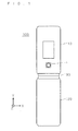
- FIG. 1 shows an outline of a mobile phone 100 in which the camera unit 1 according to one embodiment of the present invention is mounted.
- the mobile phone 100 mainly includes an image capturing/reproducing part 110 and a main body part 120.
- the image capturing/reproducing part 110 and the main body part 120 are coupled via a rotatable hinge part 130, and can be folded by the hinge part 130.
- the image capturing/reproducing part 110 has the camera unit 1 and a display part which is located at the back side in FIG. 1 .
- the main body part 120 has various operation keys such as a numeric keypad, and a control part which controls a whole of the mobile phone 100.
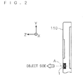
- FIG. 2 is a cross-sectional view of a part of the image capturing/reproducing part 110.
- the camera unit 1 is assembled in the image capturing/reproducing part 110 in such a posture that an object side thereof faces outwardly of the image capturing/reproducing part 110 along the optical axis A thereof.
- the camera unit 1 is a small-size image pickup device whose XY cross-sectional size is approximately 5 mm square and whose thickness in the Z-axis direction is approximately 3 mm. That is, the camera unit 1 is a so-called micro camera unit (MCU).
- MCU micro camera unit
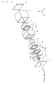
- FIG. 3 is an exploded perspective view of the camera unit 1.
- FIG. 4(a)(b) is a cross-sectional view of the camera unit 1 as sectioned along a plane including the optical axis A.
- the camera unit I mainly includes an image pickup sensor section 11, an outer frame section 12, an infrared-cutting filter section 13, a first parallel leaf spring 14, a fixing frame section 15, a lens unit 16, a second parallel leaf spring 17, an actuator 18, a coupling plate 19, a biasing spring 20 and a covering section 21.
- the image pickup sensor section 11 is a chip having an image pickup element (for example, a CMOS sensor or a CCD sensor) for imaging a light incident from the object side.
- Various terminals (not shown) for giving a drive signal to the image pickup sensor section 11 and for reading a detection signal from the image pickup sensor section 11 are provided on a back surface (surface at the -Z side) of the image pickup sensor section 11.
- the outer frame section 12 is a substantially tubular member which accommodates the image pickup sensor section 11, the infrared-cutting filter section 13, the first parallel leaf spring 14, the fixing frame section 15, the lens unit 16, the second parallel leaf spring 17, the actuator 18, the coupling plate 19, and the biasing spring 20.
- the outer frame section 12 is formed of a resin, for example. As shown in FIG. 4 , end portions of the outer frame section 12 at the +Z side and at the -Z side are sealed by the covering section 21 and the image pickup sensor section 11, respectively, and thereby an interior space of the outer frame section 12 is protected from dust and an external force.
- the infrared-cutting filter section 13 is a chip having a filtering film which filters out an infrared ray incident from the object side.
- the infrared-cutting filter section 13 is formed by, for example, forming a plurality of thin films having different refractive indexes on an upper surface of a substrate made of a glass or a transparent resin, by sputtering or the like.
- the infrared-cutting filter section 13 serves to block a light in a specific wavelength band by using the thicknesses and the refractive indexes of the plurality of thin films.
- the fixing frame section 15 is a substantially tubular member which fixes the first parallel leaf spring 14, the second parallel leaf spring 17, and the actuator 18, and regulates a positional relationship among them.
- the fixing frame section 15 is formed of a resin, for example.
- An outside surface of the fixing frame section 15 is fixed to an inside surface of the outer frame section 12 by an adhesive, for example.
- the first parallel leaf spring 14 and the second parallel leaf spring 17 are fixed to the inside of the fixing frame section 15, and the actuator 18 is fixed to an object-side surface of the fixing frame section 15.
- An abutment portion 151 is formed at an end portion of the fixing frame section 15 at the -Z side.
- the abutment portion 151 protrudes inwardly (in a direction approaching the optical axis A), and a surface of the abutment portion 151 at the +Z side is in contact with a surface of the lens unit 16 at the -Z side.
- the abutment portion 151 is in contact with the surface of the lens unit 16 at the -Z side, and thereby serves to inhibit the lens unit 16 from getting closer to the image pickup sensor section 11 than a predetermined distance.
- a penetrating electrode 152 extending in the Z-axis direction is buried in the fixing frame section 15 by insert molding.
- An end of the penetrating electrode 152 at the -Z side is connected to an electrical wiring within the mobile phone 100 by a solder or the like.
- An end of the penetrating electrode 152 at the +Z side is connected to later-described heater layers 182b and 183b of the actuator 18 via later-described electrode pads 182e and 183e.
- the first parallel leaf spring 14 and the second parallel leaf spring 17 form an elastic support section for supporting the lens unit 16 displaceably along the optical axis A.
- the first parallel leaf spring 14 and the second parallel leaf spring 17 have fixed portions 14a and 17a fixed to the fixing frame section 15, and moving portions 14b and 17b positioned inside the fixed portions 14a and 17a and fixed to the lens unit 16.
- Each of the first parallel leaf spring 14 and the second parallel leaf spring 17 is, for example, a single thin plate made of a metal (such as stainless, etc.) formed by press working or etching.
- the moving portions 14b and 17b are elastically displaceable relative to the fixed portions 14a and 17a.
- the fixed portions 14a and 17a are fixed to the inside of the fixing frame section 15 by an adhesive, for example.
- the moving portions 14b and 17b are fixed to an outside surface of the lens unit 16 by an adhesive, for example.
- the first parallel leaf spring 14 and the second parallel leaf spring 17 are shaped such that the moving portions 14b and 17b are arranged obliquely, so that the fixed portions 14a and 17a and the moving portions 14b and 17b are positioned adjacent to each other.
- the moving portions 14b and 17b are positioned at central portions of the first parallel leaf spring 14 and the second parallel leaf spring 17, respectively.
- FIG. 5(a)(b) schematically shows a function of the first parallel leaf spring 14 and the second parallel leaf spring 17.
- the lens unit 16 is fixed to the moving portions 14b and 17b of the first parallel leaf spring 14 and the second parallel leaf spring 17, respectively.
- the first parallel leaf spring 14 and the second parallel leaf spring 17 constitute a so-called parallel linkage which deforms while maintaining a parallel state therebetween. Therefore, when a force in a direction along the optical axis A acts on the lens unit 16, the lens unit 16 is moved along the optical axis A without being inclined (a state shown in FIG. 5(b) ).
- the lens unit 16 is an optical unit having a plurality of lenses and a lens holder.
- the plurality of lenses held within the lens unit 16 are made of a transparent resin, a glass, or the like, and serve to form, on the image pickup sensor section 11, an image of a light incident from the object side.
- a protrusion protruding outwardly (in a direction away from the optical axis A) is formed on an outer circumferential surface of the lens unit 16.
- the moving portions 14b and 17b of the first parallel leaf spring 14 and the second parallel leaf spring 17, respectively, are fixed to surfaces of the protrusion at the -Z side and at the +Z side.
- the actuator 18 is a member for moving the lens unit 16 by applying a force in the Z-axis direction to the lens unit 16.
- the actuator 18 has a fixed portion 181 and a pair of beam-like driving portions 182 and 183.
- the fixed portion 181 is fixed to the fixing frame section 15.
- the driving portions 182 and 183 are at the +Y side and at the -Y side of the fixed portion 181, and extend toward the -X side and the +X side, respectively.
- the fixed portion 181 is fixed to a surface of the fixing frame section 15 at the +Z side, by an adhesive, for example.
- FIG. 6(a)(b) is a cross-sectional view of the driving portion 182 of the actuator 18 as sectioned along a plane parallel to the XZ plane.
- the driving portion 182 of the actuator 18 has a structure in which a silicon layer 182a, a heater layer 182b, an insulation layer 182c, and a metal layer 182d are laminated in the Z-axis direction.
- the silicon layer 182a is a substrate having, as a main component, silicon which has a lower coefficient of thermal expansion than that of the metal layer 182d.
- the heater layer 182b is formed on a surface of the silicon layer 182a at the -Z side, by vapor deposition, sputtering, or the like.
- the heater layer 182b is made of a metal material such as platinum in which Joule heat is generated by energization.
- the insulation layer 182c is formed on a surface of the heater layer 182b at the -Z side, by CVD, sputtering, or the like.
- the insulation layer 182c is made of a material such as silicon dioxide (SiO 2 ) capable of providing electrical insulation between the heater layer 182b and the metal layer 182d.
- the metal layer 182d is formed on a surface of the insulation layer 182c at the -Z side.
- the metal layer 182d is made of a material that provides easiness of manufacturing and has a larger coefficient of thermal expansion than that of the silicon layer 182a. Examples of the material include aluminum, nickel, or zinc. When aluminum is used, the metal layer 182d is formed at the -Z side of the insulation layer 182c, by vapor deposition or sputtering. When nickel or zinc is used, the metal layer 182d is formed at the -Z side of the insulation layer 182c, by vapor deposition, sputtering, or electroplating.
- the penetrating electrode 152 in the fixing frame section 15 has its end at the +Z side connected to the heater layer 182b of the driving portion 182 via an electrode pad 182e.
- the penetrating electrode 152 and the electrode pad 182e are connected to each other by a solder or a conductive adhesive, for example.
- FIG. 6(a)(b) shows a configuration of only one driving portion 182 of the actuator 18, a configuration of the other driving portion 183 of the actuator 18 is equivalent thereto.
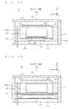
- FIG. 7 shows the actuator 18 as seen from the -Z side.
- the heater layer 182b of the driving portion 182 and the heater layer 183b of the driving portion 183 are electrically connected to each other, via a conductive portion 181a which is formed along a surface of the fixed portion 181 at the -Z side.
- the current given from the penetrating electrode 152 is sequentially supplied to the heater layers 182b and 183b of the two driving portions 182 and 183, so that heat is generated in the respective heater layers 182b and 183b.
- the heat generation in the heater layers 182b and 183b bend the driving portions 182 and 183, and thus the heater layers 182b and 183b themselves are also bent as shown in FIG. 6(b) .
- a cross-sectional area (cross-sectional area along a YZ plane) of each of the heater layers 182b and 183b is reduced, and a current path of each of the heater layers 182b and 183b is extended. Therefore, an electrical resistance value of the heater layers 182b and 183b increases.
- a detector which detects such a variation of the electrical resistance value of the heater layers 182b and 183b is provided in a drive circuit (not shown) of the actuator 18.
- the drive circuit of the actuator 18 controls a current value of a current supplied to the heater layers 182b and 183b, while detecting the variation of the electrical resistance value of the heater layers 182b and 183b. Thereby, the drive circuit of the actuator 18 controls the amount of displacement of the distal end portions 182A and 183A of the driving portions 182 and 183.
- the current paths of the heater layers 1826 and 183b are long in lengthwise directions (X-axis direction) of the respective driving portions 182 and 183.
- the current paths of the heater layers 182b and 183b may have folded shapes in which the current paths are folded back in portions near end portions of the respective driving portions 182 and 183 at the +X side and at the -X side.
- the coupling plate 19 is a relay member which couples the distal end portions 182A and 183A of the two driving portions 182 and 183 of the actuator 18 to the lens unit 16.
- the coupling plate 19 has a central portion 191 having a circular-plate shape and a pair of leg portions 192 and 193 extending from the central portion 191.
- the central portion 191 is fixed to a surface of the lens unit 16 at the +Z side.
- the pair of leg portions 192 and 193 are connected to the distal end portions 182A and 183A of the driving portions 182 and 183, respectively.
- the pair of distal end portions 182A and 183A and the pair of leg portions 192 and 193 are connected by, for example elastic bonding using a silicon rubber.
- the pair of leg portions 192 and 193 themselves are elastically deformable, the pair of distal end portions 182A and 183A and the pair of leg portions 192 and 193 may be connected to each other in a fixed manner.
- the biasing spring 20 is a so-called coiled spring made of a metal wire having a helical shape.
- the biasing spring 20 is, while being compressed from its natural length, interposed between the coupling plate 19 and the covering section 21. Consequently, the biasing spring 20 biases the coupling plate 19, the pair of driving portions 182 and 183 of the actuator 18, and the lens unit 16 toward the -Z side, by the resilient force thereof.
- a current equal to or greater than a predetermined value is not supplied to the actuator 18, the lens unit 16 has its surface at the -Z side brought into contact with the abutment portion 151 of the fixing frame section 15 by a biasing force of the biasing spring 20.
- the camera unit 1 performs an operation for moving the lens unit 16 to the most appropriate focus position when an autofocus is executed, or the like. In the following, the operation for moving the lens unit 16 will be described.
- the lens unit 16 is pressed to the abutment portion 151 of the fixing frame section 15 by the biasing force of the biasing spring 20. That is, the lens unit 16 is at rest with its surface at the -Z side being in contact with the surface of the abutment portion 151 at the +Z side (the state shown in FIG. 4(a) ).
- a current is supplied through the penetrating electrode 152 to the respective heater layers 182b and 183b of the actuator 18.
- the heater layers 182b and 183b generate heat in accordance with a value of the supplied current, to heat the respective driving portions 182 and 183 of the actuator 18.
- the driving portions 182 and 183 of the actuator 18 are heated to a temperature higher than a predetermined temperature, the driving portions 182 and 183 are deformed against the biasing force of the biasing spring 20, to integrally displace the coupling plate 19 and the lens unit 16 toward the +Z side (the state shown in FIG. 4(b) ).
- FIG. 8 schematically shows a relationship between a temperature of the pair of driving portions 182 and 183 of the actuator 18 and the amount of displacement of the distal end portions 182A and 183A of the respective driving portions 182 and 183.
- T1 the temperature of the driving portions 182 and 183
- the biasing force of the biasing spring 20 surpasses a resultant force of forces generated in the distal end portions 182A and 183A, and thus the distal end portions 182A and 183A of the driving portions 182 and 183 are not displaced.
- the lens unit 16 is at rest while being in contact with the abutment portion 151.
- a spring coefficient of the biasing spring 20 and displacement characteristics of the actuator 18 are set (selected) such that the temperature T1 can be higher than an upper limit value (for example, 60°C) of the temperature of an operating environment of the camera unit 1. Accordingly, the distal end portions 182A and 183A of the driving portions 182 and 183 are not displaced due to a change of the environmental temperature. Thus, the lens unit 16 is also not moved due to the change of the environmental temperature. That is, the position of the lens unit 16 is regulated to a predetermined position, within a predetermined temperature range including an ambient temperature.
- a current is supplied to raise the temperature of each of the driving portions 182 and 183 of the actuator 18 up to T1 or higher, thereby firstly moving the lens unit 16 at the maximum (full stroke driving). Additionally, while the lens unit 16 is being moved, a focal position is determined based on a contrast or the like of an image picked up by the image pickup sensor section 11, to calculate the most appropriate focus position of the lens unit 16.
- the drive circuit of the actuator 18 feedback-controls the value of the current supplied to the heater layers 182b and 183b while referring to the resistance value of the heater layers 182b and 183b, and displaces the distal end portions 182A and 183A of the actuator 18 such that the lens unit 16 can be moved into the most appropriate focus position.
- the driving portions 182 and 183 are cooled so that the distal end portions 182A and 183A of the driving portions 182 and 183 return to positions where they are originally located before the displacement.
- the lens unit 16 also returns to a state (normal state) of being in contact with the abutment portion 151.
- the biasing force of the biasing spring 20 assist in the movement of the lens unit 16 toward the -Z side, the lens unit 16 can return to the normal state with high responsiveness.
- the lens driving device is made up of the first parallel leaf spring 14, the fixing frame section 15, the lens unit 16, the second parallel leaf spring 17, the actuator 18, the coupling plate 19, and the biasing spring 20.
- the lens driving device of the present invention is not limited to the one made up of such a group of members.
- FIG. 9 is a cross-sectional view of a camera unit 2 according to a second embodiment of the present invention.
- the camera unit 2 of the second embodiment is different from the camera unit 1 of the first embodiment, in that the biasing spring 20 is not provided and that the first and second parallel leaf springs 14 and 17 are biased in advance.
- the other parts of the camera unit 2 of the second embodiment are substantially the same as those of the camera unit 1 of the first embodiment. Accordingly, in the following, points different from the first embodiment are mainly described.
- the parts in common with the first embodiment are denoted in FIG. 9 by the same reference numerals as those of the first embodiment, and an overlapping description will be omitted.
- the moving portions 14b and 17b of the first and second parallel leaf springs 14 and 17 are fixed to the lens unit 16 while being displaced toward the +Z side.
- the moving portions 14b and 17b of the first and second parallel leaf springs 14 and 17 constantly bias the lens unit 16 to the -Z side by their resilient force. That is, in the camera unit 1 of this embodiment, the lens unit 16 is biased toward the -Z side by the first and second parallel leaf springs 14 and 17 instead of the biasing spring 20 of the first embodiment.
- the lens unit 16 is pressed to the abutment portion 151 of the fixing frame section 15 by a biasing force of the first and second parallel leaf springs 14 and 17. That is, the lens unit 16 is at rest with its surface at the -Z side being in contact with the surface of the abutment portion 151 at the +Z side (the state shown in FIG. 9 ).
- a current equal to or greater than the predetermined value is supplied to the actuator 18 so that the driving portions 182 and 183 are heated up to a temperature higher than the predetermined temperature T1, the driving portions 182 and 183 are deformed against the biasing force of the first and second parallel leaf springs 14 and 17, to integrally displace the coupling plate 19 and the lens unit 16 toward the +Z side.
- FIG. 10 is a cross-sectional view of a camera unit 3 according to a third embodiment of the present invention.
- the camera unit 3 of the third embodiment is different from the camera unit 1 of the first embodiment, in that the biasing spring 20 is not provided and that two actuators 18 and 22 and two coupling plates 19 and 23 are provided.
- the other parts of the camera unit 3 of the third embodiment are substantially the same as those of the camera unit 1 of the first embodiment. Accordingly, in the following, points different from the first embodiment are mainly described.
- the parts in common with the first embodiment are denoted in FIG. 10 by the same reference numerals as those of the first embodiment, and an overlapping description will be omitted.
- the camera unit 3 of this embodiment has the two actuators 18 and 22.
- the actuator 22 has a fixed portion 221 fixed to a surface of the fixing frame section 15 at the -Z side, and a pair of driving portions (only one driving portion 222 of which is shown in FIG. 10 ) fixed to the coupling plate 23.
- the pair of driving portions of the actuator 22 have the same temperature-displacement characteristics as those of the pair of driving portions 182 and 183 of the actuator 18, and when a temperature rises, the pair of driving portions of the actuator 22 are displaced in a direction (-Z side) opposite to the direction (+Z side) of displacement of the pair of driving portions 182 and 183 of the actuator 18.
- the actuator 18 and the actuator 22 exert the same force in directions opposite to each other.
- the lens unit 16 receives equal forces toward the +Z side and the -Z side from the two actuators 18 and 22, respectively, and balances so that the lens unit 16 maintains its resting state without moving. That is, in this embodiment, when the environmental temperature changes, one of the two actuators 18 and 22 biases a lens in a direction opposite to a direction in which the lens unit 16 is moved by the other actuator. Thereby, the position of the lens unit 16 is regulated.
- a current may be supplied only to the actuator 18.
- the current supply to the actuator 18 may be stopped and a current may be supplied only to the actuator 22. It is not always necessary that a heater layer is provided in the actuator 22, but if a heater layer is provided, the lens unit 16 can be actively moved to the -Z side, too, which improves movement responsiveness of the lens unit 16.
- each of the camera units 1 to 3 has the pair of parallel leaf springs 14 and 17, thereby preventing the lens unit 16 from being inclined when moved in the Z-axis direction.
- only one of the parallel leaf springs 14 and 17 may be provided, so that inclination of the lens unit 16 can be prevented by one parallel leaf spring 14 (or 17) and the actuator 18.
- FIG. 11 and FIG. 12 are cross-sectional views showing cases where the parallel leaf spring 17 is removed in the camera unit 1 of the first embodiment and the camera unit 2 of the second embodiment, respectively.
- FIG. 13 is a cross-sectional view showing a case where both of the parallel leaf springs 14 and 17 are removed in the camera unit 3 of the third embodiment. Removing one or both of the parallel leaf springs 14 and 17 as shown in FIG. 11 to FIG. 13 simplifies the structures of the camera units 1 to 3, thus reducing a manufacturing cost.
- the actuator 18 includes the silicon layer 182a and the metal layer 182d having different coefficients of thermal expansion.
- the actuator of the present invention may include two kinds of metal layers having different coefficients of thermal expansion.
- the above-described silicon layer 182a may be replaced with a metal layer formed of a metal, such as invar (an alloy of iron and nickel), having a constant coefficient of thermal expansion. This enables adoption of a manufacturing method such as rolling, and thus the manufacturing cost can be reduced.
- the lens unit 16 is indirectly fixed to the pair of driving portions 182 and 183 of the actuator 18 via the coupling plate 19.
- the lens unit 16 may be directly fixed to the pair of driving portions 182 and 183 of the actuator 18.
- the lens unit 16 as a whole is moved in the Z-axis direction by the actuator 18, but a lens as a single body may be move in the Z-axis direction by the actuator 18.
- the lens unit 16 has been biased toward the -Z side, and at a time of autofocus, the lens unit 16 is moved toward the +Z side.
- the lens unit 16 has been biased toward the +Z side and at a time of autofocus, the lens unit 16 is moved toward the -Z side.
- the abutment portion 151 is formed on the fixing frame section 15, but the abutment portion 151 may be any portion as long as the position of the portion relative to the fixing frame section 15 to which the actuator 18 is fixed is not changed. Accordingly, for example, the abutment portion 151 may be formed on another member fixed to the fixing frame section 15.
- a current is supplied to the actuator 18.
- a standby current may be supplied to the actuator 18 at a time of no movement. If the pair of driving portions 182 and 183 of the actuator 18 are preheated to a temperature near the temperature T1 by the standby current, movement responsiveness of the actuator 18 can be improved.
- the temperature of the actuator 18 is controlled by the magnitude of the current supplied to the actuator 18.
- a pulse current may be given to the actuator 18, and the temperature of the actuator 18 may be controlled (duty control) by the wave number of the pulse current.
- lens driving mechanisms mounted in the camera units 1 to 3 have been described, but similar lens driving mechanisms may be applied to an optical pickup unit of an optical disc device.
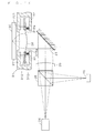
- FIG. 14 shows an exemplary optical pickup unit to which the present invention is applied.
- the optical pickup unit of FIG. 14 mainly includes a light source 24, a beam splitter 25, a collimator lens 26, a reflecting prism 27, an objective lens 28, and a light-receiving element 29.
- a light beam emitted from the light source 24 passes through the beam splitter 25, and is converted into a parallel light by the collimator lens 26, and becomes incident on the reflecting prism 27.
- the light beam reflected by the reflecting prism 27 is converged and radiated to a recording surface of the optical disk 30 by the objective lens 28.
- the optical pickup unit of FIG. 14 includes a lens driving mechanism 31 for moving the objective lens 28 in an optical axis direction.
- the lens driving mechanism 31 has a pair of parallel leaf springs 311 and 312 connected to the objective lens 28, and an actuator 313 which is deformed due to a temperature change. Additionally, between a driving portion 313a of the actuator 313 and a fixedly-installed frame 32, a biasing spring 33 is interposed while being compressed from its natural length.
- the biasing spring 33 biases the actuator 313 and the objective lens 28 in a direction opposite to a direction of displacement of the actuator 313, and brings the objective lens 28 into contact with an abutment portion 321 formed in the frame 32, thereby regulating the position of the objective lens 28. In this manner, movement of the objective lens 28 due to a change of the environmental temperature can be prevented.
Landscapes
- Physics & Mathematics (AREA)
- General Physics & Mathematics (AREA)
- Optics & Photonics (AREA)
- Lens Barrels (AREA)
- Studio Devices (AREA)
Abstract
Description
- The present invention relates to a lens driving device used for a micro camera unit (MCU) mounted in a mobile phone for example, for an optical pickup unit of an optical disc device, and the like.
- A small-size camera unit mounted in a mobile phone includes a lens driving mechanism for moving a lens, in order to realize an autofocus function and the like. As the lens driving mechanism for use in such a small-size camera unit, recently, a lens driving mechanism using a so-called bimetallic actuator has been developed. The bimetallic actuator has two metal layers having different coefficients of thermal expansion. By heating, the two metal layers are expanded with their amounts of expansion being different from each other, so that a free end is displaced relative to a fixed end.
- The bimetallic actuator has a simple structure, and therefore can be easily downsized and thinned, and additionally a relatively large amount of displacement and a relatively large generated force can be obtained. Particularly, in a small-size bimetallic actuator, power consumption can be suppressed low, too. Thus, there is a great advantage of using the bimetallic actuator in a small size lens driving mechanism.
- Conventional techniques for moving a lens of an optical apparatus by using the bimetallic actuator are disclosed in
Patent Documents -
- Patent Document 1: Japanese Patent Application Laid-Open No.
2004-81231 - Patent Document 2: Japanese Patent Application Laid-Open No.
2007-193248 - However, since the bimetallic actuator continuously changes the amount of displacement and a generated force in accordance with a temperature change, when the bimetallic actuator is used in the lens driving mechanism, a lens movement due to a change of the environmental temperature becomes a problem. To be specific, there is a problem that even when the bimetallic actuator is not actively heated, the bimetallic actuator is deformed due to a change of the environmental temperature so that the lens is moved.
- Such a problem may occur not only in the bimetallic actuator formed by laminating two metal layers, but also in a general actuator formed by laminating two layers having different coefficients of thermal expansion. Moreover, such a problem may occur not only in a lens driving device used in a camera unit for use in a mobile phone, but also in a general lens driving device for moving a lens of an optical apparatus.
- The present invention has been accomplished in view of the circumstances described above, and an object of the present invention is to provide a lens driving device and a camera unit capable of preventing a lens from being moved due to a change of the environmental temperature.
- To solve the above-described problem, an invention according to
claim 1 includes: a fixing section; an actuator having at least two layers whose coefficients of thermal expansion are different from each other, the actuator being deformed due to a temperature change so that an operating point thereof is displaced relative to one portion thereof fixed to the fixing section, the operating point being a portion other than the one portion; a lens which is directly or indirectly coupled to the operating point, and moved along with displacement of the operating point; and a regulation section which biases the lens in a direction opposite to a direction in which the lens is moved when a temperature rises, and thereby regulates a position of the lens to a predetermined position in a predetermined temperature range including an ambient temperature. - An invention according to
claim 2 is a lens driving device according toclaim 1, wherein the regulation section includes: an abutment portion formed on the fixing section or on a member fixed to the fixing section; and a biasing section which biases the lens or a unit including the lens, to bring the lens or the unit including the lens into contact with the abutment portion. - An invention according to
claim 3 is the lens driving device according toclaim 2, wherein the biasing section is a coiled spring. - An invention according to claim 4 is the lens driving device according to
claim 2, further including a pair of parallel leaf springs which elastically support the lens or the unit including the lens, wherein the biasing section biases the lens or the unit including the lens by the pair of parallel leaf springs. - An invention according to claim 5 is the lens driving device according to
claim 1, including a pair of the actuators having the same temperature-displacement characteristics and having the operating points thereof being displaced in directions opposite to each other by a temperature change, wherein, when the ambient temperature rises, one of the actuators biases the lens in a direction opposite to a direction in which the lens is moved by the other of the actuators, and thereby a position of the lens is regulated to a predetermined position in a predetermined temperature range including the ambient temperature. - An invention according to claim 6 is the lens driving device according to claim 5, further including: a pair of heaters each provided to each of the pair of actuators; and an energization section which selectively energizes the pair of heaters.
- An invention according to claim 7 is a camera unit including: a lens driving device according to any one of
claims 1 to 6; and an image pickup sensor section which images a light introduced through the lens. - According to the inventions defined in
claims 1 to 7, the lens driving device includes the regulation section which biases the lens in the direction opposite to the direction in which the lens is moved when the temperature rises, and thereby regulates the position of the lens to the predetermined position in the predetermined temperature range including the ambient temperature. Therefore, movement of the lens due to a change of an environmental temperature can be prevented. - Particularly, according to the invention defined in
claim 2, the regulation section includes the abutment portion formed on the fixing section or on the member fixed to the fixing section, and the biasing section which biases the lens or the unit including the lens, to bring the lens or the unit including the lens into contact with the abutment portion. Therefore, the position of the lens can be stably regulated to a position in contact with the abutment portion. - Particularly, according to the invention defined in
claim 3, the biasing section is a coiled spring. Therefore, a stable biasing force can be applied to the lens. - Particularly, according to the invention defined in claim 4, the lens driving device further includes the pair of parallel leaf springs which elastically support the lens or the unit including the lens, and the biasing section biases the lens or the unit including the lens by the pair of parallel leaf springs. That is, the parallel leaf springs are used as the biasing section, and therefore it is not necessary to provide the biasing section separately from the parallel leaf springs, which can simplify the configuration of the lens driving device.
- Particularly, according to the invention defined in claim 5, the lens driving device includes the pair of actuators having the same temperature-displacement characteristics and having the operating points thereof being displaced in directions opposite to each other by a temperature change, and when the ambient temperature rises, one of the actuators biases the lens in the direction opposite to the direction in which the lens is moved by the other of the actuators, and thereby the position of the lens is regulated to the predetermined position in the predetermined temperature range including the ambient temperature. This can prevent the lens from being moved due to a change of the environmental temperature, without providing any abutment portion.
- Particularly, according to the invention defined in claim 6, the lens driving device further includes the pair of heaters each provided to each of the pair of actuators, and the energization section which selectively energizes the pair of heaters. Therefore, the lens can be moved in two directions with good responsiveness.
-
- [
FIG. 1 ] shows an outline of a mobile phone in which a camera unit is mounted; - [
FIG. 2 ] is a cross-sectional view of a part of an image capturing/reproducing part; - [
FIG. 3 ] is an exploded perspective view of the camera unit; - [
FIG. 4 ] is a cross-sectional view of the camera unit as sectioned along a plane including an optical axis; - [
FIG. 5 ] schematically shows a function of first and second parallel leaf springs; - [
FIG. 6 ] is a cross-sectional view of a driving portion of an actuator; - [
FIG. 7 ] shows the actuator as seen from an image pickup sensor side; - [
FIG. 8 ] schematically shows a relationship between a temperature of a pair of driving portions of the actuator and the amount of displacement of distal end portions of the driving portions; - [
FIG. 9 ] is a cross-sectional view of a camera unit according to a second embodiment; - [
FIG. 10 ] is a cross-sectional view of a camera unit according to a third embodiment; - [
FIG. 11 ] is a cross-sectional view of a camera unit according to a modification; - [
FIG. 12 ] is a cross-sectional view of a camera unit according to a modification; - [
FIG. 13 ] is a cross-sectional view of a camera unit according to a modification; and - [
FIG. 14 ] shows an example of an optical pickup unit. - Hereinafter, preferred embodiments of the present invention will be described with reference to the drawings. Among
FIGS. 1 to 14 referred to in the following description,FIGS. 1 to 4 ,FIG. 6 ,FIG. 7 , andFIGS. 9 to 13 indicate a common XYZ orthogonal coordinate system in which a direction extending along an optical axis A of acamera unit 1 is defined as a Z-axis direction. -
FIG. 1 shows an outline of amobile phone 100 in which thecamera unit 1 according to one embodiment of the present invention is mounted. As shown inFIG. 1 , themobile phone 100 mainly includes an image capturing/reproducingpart 110 and amain body part 120. The image capturing/reproducingpart 110 and themain body part 120 are coupled via arotatable hinge part 130, and can be folded by thehinge part 130. The image capturing/reproducingpart 110 has thecamera unit 1 and a display part which is located at the back side inFIG. 1 . Themain body part 120 has various operation keys such as a numeric keypad, and a control part which controls a whole of themobile phone 100. -
FIG. 2 is a cross-sectional view of a part of the image capturing/reproducingpart 110. As shown inFIG. 2 , thecamera unit 1 is assembled in the image capturing/reproducingpart 110 in such a posture that an object side thereof faces outwardly of the image capturing/reproducingpart 110 along the optical axis A thereof. Thecamera unit 1 is a small-size image pickup device whose XY cross-sectional size is approximately 5 mm square and whose thickness in the Z-axis direction is approximately 3 mm. That is, thecamera unit 1 is a so-called micro camera unit (MCU). -
FIG. 3 is an exploded perspective view of thecamera unit 1.FIG. 4(a)(b) is a cross-sectional view of thecamera unit 1 as sectioned along a plane including the optical axis A. As shown inFIG. 3 andFIG. 4(a)(b) , the camera unit I mainly includes an imagepickup sensor section 11, anouter frame section 12, an infrared-cuttingfilter section 13, a firstparallel leaf spring 14, a fixingframe section 15, alens unit 16, a secondparallel leaf spring 17, anactuator 18, acoupling plate 19, a biasingspring 20 and acovering section 21. - The image
pickup sensor section 11 is a chip having an image pickup element (for example, a CMOS sensor or a CCD sensor) for imaging a light incident from the object side. Various terminals (not shown) for giving a drive signal to the imagepickup sensor section 11 and for reading a detection signal from the imagepickup sensor section 11 are provided on a back surface (surface at the -Z side) of the imagepickup sensor section 11. - The
outer frame section 12 is a substantially tubular member which accommodates the imagepickup sensor section 11, the infrared-cuttingfilter section 13, the firstparallel leaf spring 14, the fixingframe section 15, thelens unit 16, the secondparallel leaf spring 17, theactuator 18, thecoupling plate 19, and the biasingspring 20. Theouter frame section 12 is formed of a resin, for example. As shown inFIG. 4 , end portions of theouter frame section 12 at the +Z side and at the -Z side are sealed by the coveringsection 21 and the imagepickup sensor section 11, respectively, and thereby an interior space of theouter frame section 12 is protected from dust and an external force. - The infrared-cutting
filter section 13 is a chip having a filtering film which filters out an infrared ray incident from the object side. The infrared-cuttingfilter section 13 is formed by, for example, forming a plurality of thin films having different refractive indexes on an upper surface of a substrate made of a glass or a transparent resin, by sputtering or the like. The infrared-cuttingfilter section 13 serves to block a light in a specific wavelength band by using the thicknesses and the refractive indexes of the plurality of thin films. - The fixing
frame section 15 is a substantially tubular member which fixes the firstparallel leaf spring 14, the secondparallel leaf spring 17, and theactuator 18, and regulates a positional relationship among them. The fixingframe section 15 is formed of a resin, for example. An outside surface of the fixingframe section 15 is fixed to an inside surface of theouter frame section 12 by an adhesive, for example. The firstparallel leaf spring 14 and the secondparallel leaf spring 17 are fixed to the inside of the fixingframe section 15, and theactuator 18 is fixed to an object-side surface of the fixingframe section 15. - An
abutment portion 151 is formed at an end portion of the fixingframe section 15 at the -Z side. Theabutment portion 151 protrudes inwardly (in a direction approaching the optical axis A), and a surface of theabutment portion 151 at the +Z side is in contact with a surface of thelens unit 16 at the -Z side. Theabutment portion 151 is in contact with the surface of thelens unit 16 at the -Z side, and thereby serves to inhibit thelens unit 16 from getting closer to the imagepickup sensor section 11 than a predetermined distance. - As shown in
FIG. 4 , a penetratingelectrode 152 extending in the Z-axis direction is buried in the fixingframe section 15 by insert molding. An end of the penetratingelectrode 152 at the -Z side is connected to an electrical wiring within themobile phone 100 by a solder or the like. An end of the penetratingelectrode 152 at the +Z side is connected to later-describedheater layers actuator 18 via later-describedelectrode pads - The first
parallel leaf spring 14 and the secondparallel leaf spring 17 form an elastic support section for supporting thelens unit 16 displaceably along the optical axis A. The firstparallel leaf spring 14 and the secondparallel leaf spring 17 have fixedportions frame section 15, and movingportions portions lens unit 16. Each of the firstparallel leaf spring 14 and the secondparallel leaf spring 17 is, for example, a single thin plate made of a metal (such as stainless, etc.) formed by press working or etching. The movingportions portions portions frame section 15 by an adhesive, for example. The movingportions lens unit 16 by an adhesive, for example. - In
FIG. 3 , the firstparallel leaf spring 14 and the secondparallel leaf spring 17 are shaped such that the movingportions portions portions FIG. 4(a)(b) , for clearly showing how the movingportions portions parallel leaf spring 14 and the secondparallel leaf spring 17, respectively. -
FIG. 5(a)(b) schematically shows a function of the firstparallel leaf spring 14 and the secondparallel leaf spring 17. As shown inFIG. 5(a)(b), thelens unit 16 is fixed to the movingportions parallel leaf spring 14 and the secondparallel leaf spring 17, respectively. The firstparallel leaf spring 14 and the secondparallel leaf spring 17 constitute a so-called parallel linkage which deforms while maintaining a parallel state therebetween. Therefore, when a force in a direction along the optical axis A acts on thelens unit 16, thelens unit 16 is moved along the optical axis A without being inclined (a state shown inFIG. 5(b) ). - Reference is made to
FIG. 3 andFIG. 4 again. Thelens unit 16 is an optical unit having a plurality of lenses and a lens holder. The plurality of lenses held within thelens unit 16 are made of a transparent resin, a glass, or the like, and serve to form, on the imagepickup sensor section 11, an image of a light incident from the object side. A protrusion protruding outwardly (in a direction away from the optical axis A) is formed on an outer circumferential surface of thelens unit 16. The movingportions parallel leaf spring 14 and the secondparallel leaf spring 17, respectively, are fixed to surfaces of the protrusion at the -Z side and at the +Z side. - The
actuator 18 is a member for moving thelens unit 16 by applying a force in the Z-axis direction to thelens unit 16. Theactuator 18 has a fixedportion 181 and a pair of beam-like driving portions portion 181 is fixed to the fixingframe section 15. The drivingportions portion 181, and extend toward the -X side and the +X side, respectively. The fixedportion 181 is fixed to a surface of the fixingframe section 15 at the +Z side, by an adhesive, for example. -
FIG. 6(a)(b) is a cross-sectional view of the drivingportion 182 of theactuator 18 as sectioned along a plane parallel to the XZ plane. As shown inFIG. 6(a)(b), the drivingportion 182 of theactuator 18 has a structure in which a silicon layer 182a, aheater layer 182b, aninsulation layer 182c, and ametal layer 182d are laminated in the Z-axis direction. - The silicon layer 182a is a substrate having, as a main component, silicon which has a lower coefficient of thermal expansion than that of the
metal layer 182d. Theheater layer 182b is formed on a surface of the silicon layer 182a at the -Z side, by vapor deposition, sputtering, or the like. Theheater layer 182b is made of a metal material such as platinum in which Joule heat is generated by energization. Theinsulation layer 182c is formed on a surface of theheater layer 182b at the -Z side, by CVD, sputtering, or the like. Theinsulation layer 182c is made of a material such as silicon dioxide (SiO2) capable of providing electrical insulation between theheater layer 182b and themetal layer 182d. - The
metal layer 182d is formed on a surface of theinsulation layer 182c at the -Z side. Themetal layer 182d is made of a material that provides easiness of manufacturing and has a larger coefficient of thermal expansion than that of the silicon layer 182a. Examples of the material include aluminum, nickel, or zinc. When aluminum is used, themetal layer 182d is formed at the -Z side of theinsulation layer 182c, by vapor deposition or sputtering. When nickel or zinc is used, themetal layer 182d is formed at the -Z side of theinsulation layer 182c, by vapor deposition, sputtering, or electroplating. - The penetrating
electrode 152 in the fixingframe section 15 has its end at the +Z side connected to theheater layer 182b of the drivingportion 182 via anelectrode pad 182e. For making a stable contact between the penetratingelectrode 152 and theelectrode pad 182e, the penetratingelectrode 152 and theelectrode pad 182e are connected to each other by a solder or a conductive adhesive, for example. - When a voltage is applied to the
heater layer 182b via the penetratingelectrode 152, a current corresponding to a resistance value of theheater layer 182b flows in theheater layer 182b, and theheater layer 182b generates heat. The heat generated in theheater layer 182b is transferred to the silicon layer 182a and themetal layer 182d, to heat the silicon layer 182a and themetal layer 182d, respectively. Here, since the coefficient of thermal expansion of themetal layer 182d is larger than that of the silicon layer 182a, themetal layer 182d expands more largely than the silicon layer 182a does. As a result, as shown inFIG. 6(b) , the drivingportion 182 is bent, so that a distal end portion (operating point) 182A of the drivingportion 182 is displaced toward the +Z side. - Although
FIG. 6(a)(b) shows a configuration of only one drivingportion 182 of theactuator 18, a configuration of the other drivingportion 183 of theactuator 18 is equivalent thereto. -
FIG. 7 shows theactuator 18 as seen from the -Z side. As shown inFIG. 7 , theheater layer 182b of the drivingportion 182 and theheater layer 183b of the drivingportion 183 are electrically connected to each other, via aconductive portion 181a which is formed along a surface of the fixedportion 181 at the -Z side. The current given from the penetratingelectrode 152 is sequentially supplied to the heater layers 182b and 183b of the two drivingportions respective heater layers - The heat generation in the heater layers 182b and 183b bend the driving
portions FIG. 6(b) . At this time, a cross-sectional area (cross-sectional area along a YZ plane) of each of the heater layers 182b and 183b is reduced, and a current path of each of the heater layers 182b and 183b is extended. Therefore, an electrical resistance value of the heater layers 182b and 183b increases. A detector which detects such a variation of the electrical resistance value of the heater layers 182b and 183b is provided in a drive circuit (not shown) of theactuator 18. The drive circuit of theactuator 18 controls a current value of a current supplied to the heater layers 182b and 183b, while detecting the variation of the electrical resistance value of the heater layers 182b and 183b. Thereby, the drive circuit of theactuator 18 controls the amount of displacement of thedistal end portions portions - For more successful detection of the deformation of the driving
portions heater layers 1826 and 183b are long in lengthwise directions (X-axis direction) of therespective driving portions respective driving portions - Returning to
FIG. 3 andFIG. 4 , thecoupling plate 19 is a relay member which couples thedistal end portions portions actuator 18 to thelens unit 16. Thecoupling plate 19 has acentral portion 191 having a circular-plate shape and a pair ofleg portions central portion 191. Thecentral portion 191 is fixed to a surface of thelens unit 16 at the +Z side. The pair ofleg portions distal end portions portions distal end portions actuator 18 are displaced toward the +Z side, thecoupling plate 19 and thelens unit 16 are integrally moved to the +Z side. - In order to obtain good displacement of the pair of
distal end portions distal end portions actuator 18 and the pair ofleg portions coupling plate 19, the pair ofdistal end portions leg portions leg portions distal end portions leg portions - The biasing
spring 20 is a so-called coiled spring made of a metal wire having a helical shape. The biasingspring 20 is, while being compressed from its natural length, interposed between thecoupling plate 19 and thecovering section 21. Consequently, the biasingspring 20 biases thecoupling plate 19, the pair of drivingportions actuator 18, and thelens unit 16 toward the -Z side, by the resilient force thereof. When a current equal to or greater than a predetermined value is not supplied to theactuator 18, thelens unit 16 has its surface at the -Z side brought into contact with theabutment portion 151 of the fixingframe section 15 by a biasing force of the biasingspring 20. - The
camera unit 1 performs an operation for moving thelens unit 16 to the most appropriate focus position when an autofocus is executed, or the like. In the following, the operation for moving thelens unit 16 will be described. - As described above, when the
actuator 18 is not fed power, thelens unit 16 is pressed to theabutment portion 151 of the fixingframe section 15 by the biasing force of the biasingspring 20. That is, thelens unit 16 is at rest with its surface at the -Z side being in contact with the surface of theabutment portion 151 at the +Z side (the state shown inFIG. 4(a) ). - To move the
lens unit 16, a current is supplied through the penetratingelectrode 152 to therespective heater layers actuator 18. The heater layers 182b and 183b generate heat in accordance with a value of the supplied current, to heat therespective driving portions actuator 18. When the drivingportions actuator 18 are heated to a temperature higher than a predetermined temperature, the drivingportions spring 20, to integrally displace thecoupling plate 19 and thelens unit 16 toward the +Z side (the state shown inFIG. 4(b) ). -
FIG. 8 schematically shows a relationship between a temperature of the pair of drivingportions actuator 18 and the amount of displacement of thedistal end portions respective driving portions FIG. 8 , when the temperature of the drivingportions spring 20 surpasses a resultant force of forces generated in thedistal end portions distal end portions portions lens unit 16 is at rest while being in contact with theabutment portion 151. - When the temperature of the driving
portions distal end portions spring 20, and thus thedistal end portions portions coupling plate 19 and thelens unit 16 toward the +Z side. - In this embodiment, a spring coefficient of the biasing
spring 20 and displacement characteristics of theactuator 18 are set (selected) such that the temperature T1 can be higher than an upper limit value (for example, 60°C) of the temperature of an operating environment of thecamera unit 1. Accordingly, thedistal end portions portions lens unit 16 is also not moved due to the change of the environmental temperature. That is, the position of thelens unit 16 is regulated to a predetermined position, within a predetermined temperature range including an ambient temperature. - To perform an autofocus operation, a current is supplied to raise the temperature of each of the driving
portions actuator 18 up to T1 or higher, thereby firstly moving thelens unit 16 at the maximum (full stroke driving). Additionally, while thelens unit 16 is being moved, a focal position is determined based on a contrast or the like of an image picked up by the imagepickup sensor section 11, to calculate the most appropriate focus position of thelens unit 16. The drive circuit of theactuator 18 feedback-controls the value of the current supplied to the heater layers 182b and 183b while referring to the resistance value of the heater layers 182b and 183b, and displaces thedistal end portions actuator 18 such that thelens unit 16 can be moved into the most appropriate focus position. - When the current supply to the
actuator 18 is stopped after the imaging, the drivingportions distal end portions portions lens unit 16 also returns to a state (normal state) of being in contact with theabutment portion 151. In this embodiment, since the biasing force of the biasingspring 20 assist in the movement of thelens unit 16 toward the -Z side, thelens unit 16 can return to the normal state with high responsiveness. - In this embodiment, in the above-described
camera unit 1, the lens driving device is made up of the firstparallel leaf spring 14, the fixingframe section 15, thelens unit 16, the secondparallel leaf spring 17, theactuator 18, thecoupling plate 19, and the biasingspring 20. However, the lens driving device of the present invention is not limited to the one made up of such a group of members. -
FIG. 9 is a cross-sectional view of acamera unit 2 according to a second embodiment of the present invention. Thecamera unit 2 of the second embodiment is different from thecamera unit 1 of the first embodiment, in that the biasingspring 20 is not provided and that the first and secondparallel leaf springs camera unit 2 of the second embodiment are substantially the same as those of thecamera unit 1 of the first embodiment. Accordingly, in the following, points different from the first embodiment are mainly described. The parts in common with the first embodiment are denoted inFIG. 9 by the same reference numerals as those of the first embodiment, and an overlapping description will be omitted. - As shown in
FIG. 9 , in this embodiment, the movingportions parallel leaf springs lens unit 16 while being displaced toward the +Z side. Thus, the movingportions parallel leaf springs lens unit 16 to the -Z side by their resilient force. That is, in thecamera unit 1 of this embodiment, thelens unit 16 is biased toward the -Z side by the first and secondparallel leaf springs spring 20 of the first embodiment. - Therefore, when a current equal to or greater than a predetermined value is not supplied to the
actuator 18, thelens unit 16 is pressed to theabutment portion 151 of the fixingframe section 15 by a biasing force of the first and secondparallel leaf springs lens unit 16 is at rest with its surface at the -Z side being in contact with the surface of theabutment portion 151 at the +Z side (the state shown inFIG. 9 ). A current equal to or greater than the predetermined value is supplied to theactuator 18 so that the drivingportions portions parallel leaf springs coupling plate 19 and thelens unit 16 toward the +Z side. - In this embodiment, since it is not necessary to provide the biasing
spring 20 separately from the first and secondparallel leaf springs camera unit 2 can be simplified. -
FIG. 10 is a cross-sectional view of acamera unit 3 according to a third embodiment of the present invention. Thecamera unit 3 of the third embodiment is different from thecamera unit 1 of the first embodiment, in that the biasingspring 20 is not provided and that twoactuators coupling plates camera unit 3 of the third embodiment are substantially the same as those of thecamera unit 1 of the first embodiment. Accordingly, in the following, points different from the first embodiment are mainly described. The parts in common with the first embodiment are denoted inFIG. 10 by the same reference numerals as those of the first embodiment, and an overlapping description will be omitted. - As shown in
FIG. 10 , thecamera unit 3 of this embodiment has the twoactuators actuator 22 has a fixed portion 221 fixed to a surface of the fixingframe section 15 at the -Z side, and a pair of driving portions (only one drivingportion 222 of which is shown inFIG. 10 ) fixed to thecoupling plate 23. The pair of driving portions of theactuator 22 have the same temperature-displacement characteristics as those of the pair of drivingportions actuator 18, and when a temperature rises, the pair of driving portions of theactuator 22 are displaced in a direction (-Z side) opposite to the direction (+Z side) of displacement of the pair of drivingportions actuator 18. - In such a
camera unit 3, when an environmental temperature rises, theactuator 18 and theactuator 22 exert the same force in directions opposite to each other. Thus, thelens unit 16 receives equal forces toward the +Z side and the -Z side from the twoactuators lens unit 16 maintains its resting state without moving. That is, in this embodiment, when the environmental temperature changes, one of the twoactuators lens unit 16 is moved by the other actuator. Thereby, the position of thelens unit 16 is regulated. - To actively move the
lens unit 16 toward the +Z side at a time of autofocus or the like, a current may be supplied only to theactuator 18. To actively return thelens unit 16 to the original position after imaging, the current supply to theactuator 18 may be stopped and a current may be supplied only to theactuator 22. It is not always necessary that a heater layer is provided in theactuator 22, but if a heater layer is provided, thelens unit 16 can be actively moved to the -Z side, too, which improves movement responsiveness of thelens unit 16. - In the above, the main embodiments of the present invention have been described. However, the present invention is not limited to the above-described embodiments.
- In the embodiments described above, each of the
camera units 1 to 3 has the pair ofparallel leaf springs lens unit 16 from being inclined when moved in the Z-axis direction. However, only one of theparallel leaf springs lens unit 16 can be prevented by one parallel leaf spring 14 (or 17) and theactuator 18.FIG. 11 andFIG. 12 are cross-sectional views showing cases where theparallel leaf spring 17 is removed in thecamera unit 1 of the first embodiment and thecamera unit 2 of the second embodiment, respectively. - Both of the
parallel leaf springs lens unit 16 may be prevented only by the pair ofactuators FIG. 13 is a cross-sectional view showing a case where both of theparallel leaf springs camera unit 3 of the third embodiment. Removing one or both of theparallel leaf springs FIG. 11 to FIG. 13 simplifies the structures of thecamera units 1 to 3, thus reducing a manufacturing cost. - In the embodiments described above, the
actuator 18 includes the silicon layer 182a and themetal layer 182d having different coefficients of thermal expansion. The actuator of the present invention may include two kinds of metal layers having different coefficients of thermal expansion. For example, the above-described silicon layer 182a may be replaced with a metal layer formed of a metal, such as invar (an alloy of iron and nickel), having a constant coefficient of thermal expansion. This enables adoption of a manufacturing method such as rolling, and thus the manufacturing cost can be reduced. - In the embodiments described above, the
lens unit 16 is indirectly fixed to the pair of drivingportions actuator 18 via thecoupling plate 19. However, thelens unit 16 may be directly fixed to the pair of drivingportions actuator 18. - In the embodiments described above, the
lens unit 16 as a whole is moved in the Z-axis direction by theactuator 18, but a lens as a single body may be move in the Z-axis direction by theactuator 18. - In the embodiments described above, the
lens unit 16 has been biased toward the -Z side, and at a time of autofocus, thelens unit 16 is moved toward the +Z side. However, it may be acceptable that thelens unit 16 has been biased toward the +Z side and at a time of autofocus, thelens unit 16 is moved toward the -Z side. - In the embodiments described above, the
abutment portion 151 is formed on the fixingframe section 15, but theabutment portion 151 may be any portion as long as the position of the portion relative to the fixingframe section 15 to which theactuator 18 is fixed is not changed. Accordingly, for example, theabutment portion 151 may be formed on another member fixed to the fixingframe section 15. - In the embodiments described above, only when the
lens unit 16 is to be moved, a current is supplied to theactuator 18. However, a standby current may be supplied to theactuator 18 at a time of no movement. If the pair of drivingportions actuator 18 are preheated to a temperature near the temperature T1 by the standby current, movement responsiveness of theactuator 18 can be improved. - In the embodiments described above, the temperature of the
actuator 18 is controlled by the magnitude of the current supplied to theactuator 18. However, a pulse current may be given to theactuator 18, and the temperature of theactuator 18 may be controlled (duty control) by the wave number of the pulse current. - In the embodiments described above, the lens driving mechanisms mounted in the
camera units 1 to 3 have been described, but similar lens driving mechanisms may be applied to an optical pickup unit of an optical disc device. -
FIG. 14 shows an exemplary optical pickup unit to which the present invention is applied. The optical pickup unit ofFIG. 14 mainly includes alight source 24, abeam splitter 25, acollimator lens 26, a reflectingprism 27, anobjective lens 28, and a light-receivingelement 29. A light beam emitted from thelight source 24 passes through thebeam splitter 25, and is converted into a parallel light by thecollimator lens 26, and becomes incident on the reflectingprism 27. The light beam reflected by the reflectingprism 27 is converged and radiated to a recording surface of theoptical disk 30 by theobjective lens 28. - The optical pickup unit of
FIG. 14 includes alens driving mechanism 31 for moving theobjective lens 28 in an optical axis direction. Thelens driving mechanism 31 has a pair ofparallel leaf springs objective lens 28, and anactuator 313 which is deformed due to a temperature change. Additionally, between a driving portion 313a of theactuator 313 and a fixedly-installedframe 32, a biasingspring 33 is interposed while being compressed from its natural length. The biasingspring 33 biases theactuator 313 and theobjective lens 28 in a direction opposite to a direction of displacement of theactuator 313, and brings theobjective lens 28 into contact with anabutment portion 321 formed in theframe 32, thereby regulating the position of theobjective lens 28. In this manner, movement of theobjective lens 28 due to a change of the environmental temperature can be prevented. -
- 1-3
- camera unit
- 11
- image pickup sensor section
- 12
- outer frame section
- 13
- infrared-cutting filter section
- 14
- first parallel leaf spring
- 15
- fixing frame section
- 16
- lens unit
- 17
- second parallel leaf spring
- 18, 22, 313
- actuator
- 19, 23
- coupling plate
- 20
- biasing spring
- 21
- covering section
- 100
- mobile phone
- 151
- abutment portion
- 181, 221
- fixed portion
- 182, 183, 222, 223, 313a
- driving portion
- 182A, 183A
- distal end portion
- 182a
- silicon layer
- 182b
- heater layer
- 182d
- metal layer
- A
- optical axis
Claims (7)
- A lens driving device comprising:a fixing section;an actuator having at least two layers whose coefficients of thermal expansion are different from each other, said actuator being deformed due to a temperature change so that an operating point thereof is displaced relative to one portion thereof fixed to said fixing section, said operating point being a portion other than said one portion;a lens which is directly or indirectly coupled to said operating point, and moved along with displacement of said operating point; anda regulation section which biases said lens in a direction opposite to a direction in which said lens is moved when a temperature rises, and thereby regulates a position of said lens to a predetermined position in a predetermined temperature range including an ambient temperature.
- The lens driving device according to claim 1, wherein
said regulation section includes:an abutment portion formed on said fixing section or on a member fixed to said fixing section; anda biasing section which biases said lens or a unit including said lens, to bring said lens or the unit including said lens into contact with said abutment portion. - The lens driving device according to claim 2, wherein
said biasing section is a coiled spring. - The lens driving device according to claim 2, further comprising
a pair of parallel leaf springs which elastically support said lens or the unit including said lens,
wherein said biasing section biases said lens or the unit including said lens by said pair of parallel leaf springs. - The lens driving device according to claim 1, comprising
a pair of said actuators having the same temperature-displacement characteristics and having said operating points thereof being displaced in directions opposite to each other by a temperature change,
wherein, when the ambient temperature rises, one of said actuators biases said lens in a direction opposite to a direction in which said lens is moved by the other of said actuators, and thereby a position of said lens is regulated to a predetermined position in a predetermined temperature range including the ambient temperature. - The lens driving device according to claim 5, further comprising:a pair of heaters each provided to each of said pair of actuators; andan energization section which selectively energizes said pair of heaters.
- A camera unit comprising:a lens driving device according to claim 1; andan image pickup sensor section which images a light introduced through said lens.
Applications Claiming Priority (2)
| Application Number | Priority Date | Filing Date | Title |
|---|---|---|---|
| JP2008157760 | 2008-06-17 | ||
| PCT/JP2009/060368 WO2009154090A1 (en) | 2008-06-17 | 2009-06-05 | Lens drive device and camera unit |
Publications (2)
| Publication Number | Publication Date |
|---|---|
| EP2287647A1 true EP2287647A1 (en) | 2011-02-23 |
| EP2287647A4 EP2287647A4 (en) | 2012-07-11 |
Family
ID=41434006
Family Applications (1)
| Application Number | Title | Priority Date | Filing Date |
|---|---|---|---|
| EP09766538A Withdrawn EP2287647A4 (en) | 2008-06-17 | 2009-06-05 | Lens drive device and camera unit |
Country Status (4)
| Country | Link |
|---|---|
| US (1) | US8379334B2 (en) |
| EP (1) | EP2287647A4 (en) |
| JP (1) | JPWO2009154090A1 (en) |
| WO (1) | WO2009154090A1 (en) |
Cited By (1)
| Publication number | Priority date | Publication date | Assignee | Title |
|---|---|---|---|---|
| WO2016038513A1 (en) * | 2014-09-09 | 2016-03-17 | Actuator Solutions GmbH | Auto-focus actuator unit with dust barrier for camera module |
Families Citing this family (15)
| Publication number | Priority date | Publication date | Assignee | Title |
|---|---|---|---|---|
| WO2009154090A1 (en) | 2008-06-17 | 2009-12-23 | コニカミノルタオプト株式会社 | Lens drive device and camera unit |
| KR20110074327A (en) * | 2009-12-24 | 2011-06-30 | 주식회사 엔씰텍 | Polycrystalline silicon thin film manufacturing apparatus and manufacturing method |
| JP5470115B2 (en) * | 2010-03-16 | 2014-04-16 | アルプス電気株式会社 | Polymer actuator element and driving device using the same |
| US8651677B2 (en) * | 2010-06-28 | 2014-02-18 | Lexmark International, Inc. | Mounting mechanism for a component of an imaging apparatus, and methods of making and using same |
| US8692932B2 (en) * | 2010-11-02 | 2014-04-08 | Hong Kong Applied Science And Technology Research Institute Co., Ltd. | Compact imaging device having a laminated component |
| WO2012063701A1 (en) * | 2010-11-12 | 2012-05-18 | ソニー株式会社 | Drive device, method of manufacturing thereof, lens module, and image-pickup device |
| JP2013200366A (en) * | 2012-03-23 | 2013-10-03 | Sony Corp | Camera module and camera device |
| DE102013209819B4 (en) * | 2013-05-27 | 2018-01-25 | Fraunhofer-Gesellschaft zur Förderung der angewandten Forschung e.V. | Optical structure with webs disposed thereon and method of making the same |
| DE102013209829B4 (en) | 2013-05-27 | 2016-04-28 | Fraunhofer-Gesellschaft zur Förderung der angewandten Forschung e.V. | Optical structure with webs disposed thereon and method of making the same |
| US9780134B2 (en) * | 2014-05-16 | 2017-10-03 | Taiwan Semiconductor Manufacturing Company Ltd. | Semiconductor device and method of forming the same |
| DE102014212034A1 (en) * | 2014-06-24 | 2015-12-24 | Robert Bosch Gmbh | Method of making an imager module and a corresponding imager module |
| TWI626501B (en) * | 2016-04-08 | 2018-06-11 | 台灣東電化股份有限公司 | Camera module |
| DE102016004674B4 (en) * | 2016-04-18 | 2024-07-18 | Kastriot Merlaku | Drive system for a camera |
| CN110703536A (en) * | 2018-06-22 | 2020-01-17 | 台湾东电化股份有限公司 | Drive mechanism |
| CN113300563B (en) * | 2021-07-27 | 2021-11-19 | 基合半导体(宁波)有限公司 | Focusing motor, closed-loop control method of focusing motor and camera equipment |
Family Cites Families (18)
| Publication number | Priority date | Publication date | Assignee | Title |
|---|---|---|---|---|
| US4525745A (en) * | 1982-10-22 | 1985-06-25 | General Electric Company | Temperature compensation for TV projection lens and CRT assembly |
| JPS61159029A (en) | 1984-12-28 | 1986-07-18 | Matsushita Electric Ind Co Ltd | Gas safety device |
| JPS6242091A (en) | 1985-08-20 | 1987-02-24 | 株式会社東芝 | Shape memory alloy part |
| JPH027882A (en) | 1988-06-21 | 1990-01-11 | Canon Inc | Actuator |
| JPH03196781A (en) | 1989-12-26 | 1991-08-28 | Matsushita Electric Ind Co Ltd | Imaging correction device |
| JP2986823B2 (en) | 1990-01-06 | 1999-12-06 | トキコーポレーション株式会社 | Ti-Ni-based reversible shape memory alloy and method for producing the same |
| JP2000356275A (en) * | 1999-06-15 | 2000-12-26 | Seiko Instruments Inc | Variable pressure valve |
| JP3207841B1 (en) | 2000-07-12 | 2001-09-10 | 三菱重工業株式会社 | Aluminum composite powder and method for producing the same, aluminum composite material, spent fuel storage member and method for producing the same |
| JP3831318B2 (en) * | 2002-08-22 | 2006-10-11 | オリンパス株式会社 | Endoscopic imaging device |
| JP4458323B2 (en) * | 2003-02-13 | 2010-04-28 | キヤノン株式会社 | Holding apparatus, exposure apparatus having the holding apparatus, and device manufacturing method |
| JP4373704B2 (en) | 2003-05-09 | 2009-11-25 | 富士フイルム株式会社 | Lens drive device |
| US7265917B2 (en) * | 2003-12-23 | 2007-09-04 | Carl Zeiss Smt Ag | Replacement apparatus for an optical element |
| JP2006301202A (en) | 2005-04-19 | 2006-11-02 | Olympus Corp | Optical device and digital camera |
| JP2006340972A (en) | 2005-06-10 | 2006-12-21 | Toshiba Tec Corp | Electric vacuum cleaner |
| JP2007193248A (en) | 2006-01-23 | 2007-08-02 | Alps Electric Co Ltd | Camera module |
| US7612951B2 (en) * | 2006-03-24 | 2009-11-03 | Konica Minolta Opto, Inc. | Projection lens unit |
| US8366609B2 (en) * | 2007-09-18 | 2013-02-05 | Olympus Medical Systems Corp. | Actuator and image pickup apparatus |
| WO2009154090A1 (en) | 2008-06-17 | 2009-12-23 | コニカミノルタオプト株式会社 | Lens drive device and camera unit |
-
2009
- 2009-06-05 WO PCT/JP2009/060368 patent/WO2009154090A1/en not_active Ceased
- 2009-06-05 EP EP09766538A patent/EP2287647A4/en not_active Withdrawn
- 2009-06-05 JP JP2010517845A patent/JPWO2009154090A1/en active Pending
- 2009-06-05 US US12/999,506 patent/US8379334B2/en not_active Expired - Fee Related
Cited By (3)
| Publication number | Priority date | Publication date | Assignee | Title |
|---|---|---|---|---|
| WO2016038513A1 (en) * | 2014-09-09 | 2016-03-17 | Actuator Solutions GmbH | Auto-focus actuator unit with dust barrier for camera module |
| US9897773B2 (en) | 2014-09-09 | 2018-02-20 | Actuator Solutions GmbH | Auto-focus actuator unit with dust barrier for camera module |
| TWI651577B (en) * | 2014-09-09 | 2019-02-21 | 德商艾斯科技公司 | Autofocus actuator unit and camera module |
Also Published As
| Publication number | Publication date |
|---|---|
| US8379334B2 (en) | 2013-02-19 |
| EP2287647A4 (en) | 2012-07-11 |
| US20110096419A1 (en) | 2011-04-28 |
| WO2009154090A1 (en) | 2009-12-23 |
| JPWO2009154090A1 (en) | 2011-11-24 |
Similar Documents
| Publication | Publication Date | Title |
|---|---|---|
| US8379334B2 (en) | Lens driving device and camera unit | |
| US8588598B2 (en) | Shape memory alloy actuation apparatus | |
| US8441749B2 (en) | Shape memory alloy actuation apparatus | |
| US12049877B2 (en) | Shape memory alloy actuator | |
| US20210131405A1 (en) | Shape Memory Alloy Actuators And Methods Thereof | |
| US8073320B2 (en) | Shape memory alloy actuation apparatus | |
| US11306706B2 (en) | Shape memory alloy actuators and methods thereof | |
| JP5381643B2 (en) | Optical device and imaging unit | |
| EP3864445B1 (en) | Optical device with a light ray deflector | |
| US20110226392A1 (en) | Drive device, lens barrel, image pickup apparatus, lens drive method and method of producing shape memory alloy | |
| KR20210143285A (en) | Shape memory alloy actuator and method therefor | |
| US20110102917A1 (en) | Drive mechanism, drive device, and lens drive device | |
| WO2006054535A1 (en) | Lens barrel, imaging device with the lens barrel, and method of producing the imaging device | |
| US7400462B2 (en) | Optical system having lenses with adjustable focal length | |
| WO2011062209A1 (en) | Optical material, optical unit, and imaging unit | |
| JP4995752B2 (en) | Drive module and electronic device including the same | |
| JP2005134835A (en) | IMAGING DEVICE AND IMAGING DEVICE HAVING IMAGING DEVICE | |
| JP2007127936A (en) | Imaging apparatus having prism optical system | |
| HK40059472A (en) | Optical device with a light ray deflector | |
| HK40059472B (en) | Optical device with a light ray deflector | |
| JP2010074986A (en) | Drive device, imaging device equipped with the same, and electronic equipment equipped with the drive device or imaging device | |
| KR20070062688A (en) | Camera module and its manufacturing method | |
| JP2011197189A (en) | Optical device, camera shake correcting device, and imaging unit |
Legal Events
| Date | Code | Title | Description |
|---|---|---|---|
| PUAI | Public reference made under article 153(3) epc to a published international application that has entered the european phase |
Free format text: ORIGINAL CODE: 0009012 |
|
| 17P | Request for examination filed |
Effective date: 20101213 |
|
| AK | Designated contracting states |
Kind code of ref document: A1 Designated state(s): AT BE BG CH CY CZ DE DK EE ES FI FR GB GR HR HU IE IS IT LI LT LU LV MC MK MT NL NO PL PT RO SE SI SK TR |
|
| AX | Request for extension of the european patent |
Extension state: AL BA RS |
|
| DAX | Request for extension of the european patent (deleted) | ||
| A4 | Supplementary search report drawn up and despatched |
Effective date: 20120611 |
|
| RIC1 | Information provided on ipc code assigned before grant |
Ipc: G02B 7/04 20060101AFI20120604BHEP |
|
| STAA | Information on the status of an ep patent application or granted ep patent |
Free format text: STATUS: THE APPLICATION HAS BEEN WITHDRAWN |
|
| 18W | Application withdrawn |
Effective date: 20140912 |