EP2287568A1 - Model based method to assess road curvature effect on travel time and comfort for route planning - Google Patents
Model based method to assess road curvature effect on travel time and comfort for route planning Download PDFInfo
- Publication number
- EP2287568A1 EP2287568A1 EP20100171608 EP10171608A EP2287568A1 EP 2287568 A1 EP2287568 A1 EP 2287568A1 EP 20100171608 EP20100171608 EP 20100171608 EP 10171608 A EP10171608 A EP 10171608A EP 2287568 A1 EP2287568 A1 EP 2287568A1
- Authority
- EP
- European Patent Office
- Prior art keywords
- path
- speed
- waypoints
- optimal
- profile
- Prior art date
- Legal status (The legal status is an assumption and is not a legal conclusion. Google has not performed a legal analysis and makes no representation as to the accuracy of the status listed.)
- Granted
Links
Images


Classifications
-
- G—PHYSICS
- G01—MEASURING; TESTING
- G01C—MEASURING DISTANCES, LEVELS OR BEARINGS; SURVEYING; NAVIGATION; GYROSCOPIC INSTRUMENTS; PHOTOGRAMMETRY OR VIDEOGRAMMETRY
- G01C21/00—Navigation; Navigational instruments not provided for in groups G01C1/00 - G01C19/00
- G01C21/26—Navigation; Navigational instruments not provided for in groups G01C1/00 - G01C19/00 specially adapted for navigation in a road network
- G01C21/34—Route searching; Route guidance
- G01C21/3453—Special cost functions, i.e. other than distance or default speed limit of road segments
- G01C21/3492—Special cost functions, i.e. other than distance or default speed limit of road segments employing speed data or traffic data, e.g. real-time or historical
-
- G—PHYSICS
- G01—MEASURING; TESTING
- G01C—MEASURING DISTANCES, LEVELS OR BEARINGS; SURVEYING; NAVIGATION; GYROSCOPIC INSTRUMENTS; PHOTOGRAMMETRY OR VIDEOGRAMMETRY
- G01C21/00—Navigation; Navigational instruments not provided for in groups G01C1/00 - G01C19/00
- G01C21/26—Navigation; Navigational instruments not provided for in groups G01C1/00 - G01C19/00 specially adapted for navigation in a road network
- G01C21/34—Route searching; Route guidance
- G01C21/3453—Special cost functions, i.e. other than distance or default speed limit of road segments
- G01C21/3461—Preferred or disfavoured areas, e.g. dangerous zones, toll or emission zones, intersections, manoeuvre types or segments such as motorways, toll roads or ferries
-
- G—PHYSICS
- G06—COMPUTING OR CALCULATING; COUNTING
- G06F—ELECTRIC DIGITAL DATA PROCESSING
- G06F17/00—Digital computing or data processing equipment or methods, specially adapted for specific functions
- G06F17/10—Complex mathematical operations
- G06F17/18—Complex mathematical operations for evaluating statistical data, e.g. average values, frequency distributions, probability functions, regression analysis
-
- G—PHYSICS
- G06—COMPUTING OR CALCULATING; COUNTING
- G06F—ELECTRIC DIGITAL DATA PROCESSING
- G06F9/00—Arrangements for program control, e.g. control units
- G06F9/06—Arrangements for program control, e.g. control units using stored programs, i.e. using an internal store of processing equipment to receive or retain programs
- G06F9/44—Arrangements for executing specific programs
- G06F9/448—Execution paradigms, e.g. implementations of programming paradigms
- G06F9/4494—Execution paradigms, e.g. implementations of programming paradigms data driven
Definitions
- the present application relates generally to ground based route planning. Specifically, the present application provides methods and systems for assessing the effect of road curvature on the travel time and the comfort level of a path determined by a ground based route planning system.
- the presently disclosed subject matter is equally amenable to other like applications and/or environments.
- Some ground based route planning systems and/or methods refine estimated traversal times along a path using recorded data from professional drivers.
- refinements are specific to driver preferences and dependent upon traffic conditions.
- refinements are labor intensive and expensive in that they require a driver to traverse every road along a path. Accordingly, it would be advantageous to have a system and/or method that is agnostic to driver preferences and specific traffic conditions, and does not require a driver to traverse all roads that may be used for a path.
- ground based route planning systems and/or methods generally fail to take into account considerations pertaining to the comfort level a user of a ground based route planning system will experience while traversing a path. Instead, such systems focus on the shortest or fastest path between two points. However, it seems axiomatic that many users would be willing to trade a few minutes of additional travel time, or a few extra miles of travel, for an increased comfort and safety level while traversing a path. Accordingly, it would be advantageous to have a ground based route planning system and/or method that takes into consideration the comfort level and safety a user will experience while traversing a path.
- While some ground based route planning systems may take into account driver comfort by virtue of encouraging the use of highways, they fail to take into account one particular consideration directly affecting the comfort level of a user while traversing a path: the curvature of the path.
- the curvature of the path Namely, a NASA study found that the risk of car sickness is increased by acceleration at particular frequencies. Generally, these frequencies fall around the 0.2 hertz mark.
- the curvature variation of a road directly effects the acceleration of a vehicle, both cross track and along track, the curvature of a road may have an effect on the comfort level of an individual.
- curvy roads present more of a driving challenge because of the increased alertness required to traverse such roads, whereby the curvature of a road may affect the comfort level of an individual in spite of motion sickness.
- curvature of a road has an effect on the comfort level of a user, whereby it would be advantageous to have a system and/or method that considers the curvature of roads while determining a path and/or notifies the user of any potential discomfort that might occur.
- the present application contemplates a new and improved system and/or method which overcomes the above-referenced problems and others
- a method and system for assessing road curvature of a path includes a plurality of waypoints.
- An allowable speed profile of the path is determined.
- the allowable speed profile includes an allowable speed for the each of the plurality of waypoints.
- the allowable speed for the each of the plurality of waypoints satisfies a cross track acceleration constraint.
- An optimal speed profile of the path is also determined.
- the optimal speed profile includes an optimal speed for the each of the plurality of waypoints.
- the optimal speed for the each of the plurality of waypoints satisfies both an along track acceleration constraint and a speed constraint.
- the speed constraint is a minimum of the desired speed and the allowable speed.
- FIGURE 1 is an exemplary method for assessing road curvature of a path
- FIGURE 2 is a graphical illustration of a path
- FIGURE 3 is a graphical illustration of a portion of the path of FIGURE 2 illustrating the determination of the radius of curvature of a waypoint;
- FIGURE 4 is a graphical illustration of the speed restraints placed upon the traversal of the path in FIGURE 2 ;
- FIGURE 5 is a graphical illustration of the optimal speed profile of the path of FIGURE 2 ;
- FIGURE 6 is an exemplary system for assessing the curvature of a path
- FIGURE 7 is an exemplary road curvature assessor employing the exemplary method for assessing road curvature of a path
- FIGURES 8-9 are graphical illustrations of paths generated in accordance with two exemplary algorithms for finding the shortest path between two points;
- FIGURES 10-13 are graphical illustrations of the results of performing the exemplary method of the present application on a path generated in accordance with the first exemplary algorithm illustrated in FIGURE 8 ;
- FIGURES 14-17 are graphical illustrations of the results of performing the exemplary method of the present application on a path generated in accordance with the second exemplary algorithm illustrated in FIGURE 9 .
- An exemplary method for assessing road curvature of a path presupposes a path generated by a ground based route planning system.
- the ground based route planning system refers to electronic services such as MapQuest TM , TomTom TM , and other like services. Further, the ground based route planning system may refer to a website (e.g., MapQuest TM ), a handheld GPS unit (e.g., TomTom TM ), or other like variations thereon.
- a ground based route planning system generates a path between a start address and an end address entered by the user of the ground based route planning system.
- the generated path is generally used to generate driving directions and/or a driving time, such that the generated path tracks along roads, highways, freeways, and other like ground based paths.
- the generated path may be comprised of a plurality of paths (or sub-paths) corresponding to individual roads, highways, etc.
- the present application is equally amenable to "off-road" path generation, or variations thereon, where the user of a ground based route planning system may, for example, enter start coordinates and end coordinates.
- the path generally refers to the fastest and/or the shortest path between two points.
- the path may be generated using A* with visibility graphs, fast marching with gradient descent, or any other algorithm operative to generate a path between two points.
- low time complexity algorithms are used.
- the path further includes a plurality of waypoints, where the waypoints correspond to points along the path generated by the ground based route planning system.
- FIGURE 1 the exemplary method will be described as shown in FIGURE 1 .
- the exemplary method seeks to assess the curvature of a path generated by, for example, MapQuest TM to determine the travel time for the path and/or the comfort level of the path.
- the steps of FIGURE 1 will be described in conjunction with FIGURES 2-5 , as appropriate.
- FIGURE 2 is a graphical illustration of a path.
- FIGURE 3 is a graphical illustration of a portion of the path of FIGURE 2 illustrating the determination of the radius of curvature of a waypoint.
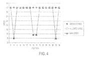
- FIGURE 4 is a graphical illustration of the speed constraints placed upon the traversal of the path in FIGURE 2 .
- FIGURE 5 is a graphical illustration of the optimal speed profile of the graph of FIGURE 2 .
- an exemplary method for assessing road curvature of a path includes the steps of generating the path from a pre-path (optional step 102); determining an allowable speed profile (Step 104); and determining an optimal speed profile (Step 106).
- the method further includes determining the optimal travel time of the optimal speed profile (Step 108), and determining comfort level (Step 110).
- the step of determining an optimal speed profile (Step 106) includes the steps of determining speed constraints (Step 112), determining a speed profile satisfying a negative acceleration constraint (Step 114), and updating the speed profile to satisfy a positive acceleration constraint (Step 116).
- the step of determining the comfort level (Step 110) includes the step of determining the frequency response of the path (Step 118).
- the first, albeit optional, step is generating a path from a pre-path (Step 102).
- the pre-path is the path provided by the ground based route planning system.
- This step entails generating a finer sampling of waypoints than the pre-path, such that the finer sampling of waypoints defines a space-indexed path, w ⁇ R N x 2 , with a curvature that can be numerically estimated.
- N is the number of waypoints.
- the pre-path may be either time-index or space-indexed. If the pre-path is time-index, it is converted into a space-indexed path.
- the finer the sample of waypoints the more accurate the exemplary method will be able to assess the road curvature.
- a finer sampling of waypoints is generally better, it comes at the cost of an increase in computation time. Accordingly, the amount of discretization of the pre-path must be chosen in view of the competing interests of computation time and accuracy.
- Step 104 the next step is to determine an allowable speed profile for the path.
- the cross track acceleration constraint a max depends upon a number of considerations, including, but not limited to, comfort, vehicle capabilities, road conditions, and/or other like considerations.
- the cross track acceleration a ct,i at waypoint w i is a function of the velocity v i and the radius of curvature r i .
- waypoints w i -1 , w i , and w i +1 are used to define a circle through those waypoints.
- This circle is assumed to have radius of curvature r i , because, as should be appreciated, this is a valid assumption when the waypoints are finely spaced relative to their curvature.
- Waypoints w i -1 and w i define a first line
- waypoints w i and w i +1 define a second line. The intersection of the perpendicular lines through the midpoints of the first line and the second line is at the center of the circle.
- the center point can be computed using the equations above.
- the radius of curvature r i is the norm of the vector connecting w i and the center c i .
- the direction of the curve can be computed for a finite radius of curvature r i using the sign of the cross product of the first and second line segments.
- FIGURE 2 a graph of a path is illustrated, wherein the path includes a plurality of waypoints.
- the graph includes an x-axis and a y-axis, where each point on the graph corresponds to a waypoint.
- the graph further shows a dashed box enclosing three waypoints: w i -1 , w i , and w i +1 . These three waypoints will be used to illustrate how the radius of curvature r i of waypoint w i is determined.
- the first step is to determine first line 302 between waypoints w i -1 and w i and second line 304 between waypoints w i and w i +1 as shown in FIGURE 2 .
- an intersection between a first perpendicular line 306 and a second perpendicular line 308 is determined. The intersection corresponds to the center c i of a circle through waypoints w i -1 , w i , and w i +1 .
- the first perpendicular line 306 is perpendicular to the first line 302 and runs through the midpoint of the first line 302.
- the second perpendicular line 308 is perpendicular to the second line 304 and runs through the midpoint of the second line 304.
- the radius of curvature r i is simply the length (or norm) of a line extending between the center c i of the circle and waypoint w i .
- the optimal speed profile of the path is determined (Step 106).
- This step entails determining the optimal speed profile satisfying piecewise linear along track acceleration constraints, as well as the minimum of the desired speed and of the allowable speed from the previous step.
- This step includes the sub steps of determining speed constraints (Step 112), determining a speed profile satisfying a negative along track acceleration constraint (Step 114), and updating the speed profile to satisfy a positive along track acceleration constraint (Step 116).
- the speed at every waypoint is constrained by both the desired velocity v i,max and by the constraint imposed for the cross track acceleration constraint v i,allow .
- the pre-path preferably defines the desired velocity.
- the desired velocity for a particular waypoint may, for example, be the speed limit along a road corresponding to the waypoint.
- the desired speed may be dependent upon the capabilities of the vehicle traversing the path, such as the top speed of the vehicle. Notwithstanding how the desired velocity is chosen, the minimum of these two constraints must be satisfied, whereby the maximum velocity v i allowed at each waypoint is defined as shown below.
- v ⁇ i min v i , max ⁇ v i , allow
- each waypoint is graphed according to speed and position along the path of FIGURE 2 .
- the allowed speed corresponds to the allowed speed according to the cross track acceleration constraint (i.e., Step 104).
- the desired speed corresponds to the desired speed, as discussed above. In this case, the desired speed for each waypoint was chosen arbitrarily for illustrative purposes.
- the max speed i.e., the speed constraint
- the minimum of the desired speed and the allowed speed corresponds to the minimum of the desired speed and the allowed speed.
- Step 112 a speed profile satisfying a negative along track acceleration constraint is first determined (Step 114). Thereafter, the speed profile from Step 114 is updated so as to satisfy a positive along track acceleration constraint (Step 116).
- these steps rely upon three equations: the time between waypoints ⁇ t , the speed at the next waypoint v i +1 , and the along track acceleration a at,i . Further, these steps rely upon Algorithm 1. Accordingly, these equations, as well as Algorithm 1, are presented below.
- v i + 1 v i 2 - 2 ⁇ a at , i ⁇ s i - s i + 1
- Algorithm 1 operates by incrementing through the waypoints. At waypoint w i , it first determines if it is possible to accelerate between w i and w i +1 . If it can accelerate, it accelerates as fast as required, or saturates at a max . If it cannot accelerate, it next checks if it must slow down to satisfy v i +1 . If it must, it slows down to that speed, using whatever acceleration necessary, even if using a at,i ⁇ - a max is required. Note that it only violates a max to slow down. If it does not need to slow down, then it holds the current speed.
- Step 114 the next step is to determine an acceleration profile satisfying a negative along track acceleration constrain. This step is accomplished by using Algorithm 1, shown above, to perform a reverse sweep of the waypoints. To begin, all along track positions are stored in s and all maximum speeds are stored in v . As should be appreciated, maximum speeds are determined in Step 112 (i.e., the speed constraint). Thereafter, to prepare for sweeping through the points from the end to the beginning, these arrays, s and v , are reversed in time, and s is negated.
- the result is that the speed profile satisfies the negative along track acceleration constraint - a max .
- Step 114 After a speed profile satisfying a negative along track acceleration constraint is determined (Step 114), the speed profile is updated to further satisfy a positive along track acceleration constraint (Step 116) using Algorithm 1. This is accomplished via the use of a forward sweep of the waypoints. To begin, the speed constraint v is set to the resulting v from Step 114 (i.e., the reverse sweep). Thereafter, to prepare for sweeping through the points from beginning to end, the arrays, s and v , are again reversed in time, and s is again negated.
- the speed profile satisfies both the negative along track acceleration constraint and the positive along track acceleration constraint, as well as the speed constraint from Step 112.
- the optimal speed profile has been generated.
- a corresponding acceleration profile and a corresponding time profile are generated.
- negative along track acceleration constraint - a max is shown as the negative of the positive along track acceleration constraint a max , it should be appreciated that they need not be symmetrical.
- FIGURE 5 a graphical illustration of the speed profile after sweep two (i.e., the optimal speed profile) of the graph of FIGURE 2 is shown.
- FIGURE 5 further includes the speed profile after sweep one and the speed constraint from Step 112.
- the speed constraint imposes an upper bound on speeds for the first sweep, such that the speeds within the speed profile of the first sweep do not exceed the desired speed and the cross track acceleration constraint.
- the speed profile after the first sweep imposes an upper bound on speeds for the second sweep, such that the speeds within the speed profile of the second sweep do not exceed the desired speed, the cross track acceleration constraint, and the negative along track acceleration constraint.
- speeds within the speed profile of sweep one may not exceed speeds in the speed constraint profile
- speeds within the speed profile of sweep two may not exceed speeds in the speed profile of sweep one.
- the speed profile after sweep one shows acceleration from right to left until the speed meets the speed constraint.
- the speed profile after sweep two accelerates from left to right until the speed meets the speed profile from the first sweep.
- the method may proceed according to one or both of two optional steps.
- This step includes the sub step of determining the frequency response of the path (Step 118).
- the first is to collect real-time driving data for a path. As should be apparent, under such a method, one needs to physically traverse the path and collect data about the frequency response of the path.
- the frequency response is determined from the optimal speed profile, and corresponding cross track and/or along track acceleration profiles. Using this approach, acceleration profiles are converted so they are time-indexed, as opposed to space indexed. Thereafter, to get the frequency response, a digital filtering method, such as finite impulse response, Fourier transform, and so forth, is performed on the relevant acceleration profiles.
- the frequency response With the frequency response, one may determine whether the frequency response includes frequencies prone to causing motion sickness. As previously mentioned, a study from NASA released a table (see Table 1 below) detailing those frequencies prone to causing motion sickness. Particularly, Table 1 plots frequency (in hertz) versus acceleration (in gravitational units). The generated curves (25 percent, 50 percent, 75 percent) represent equal motion sickness contours based on percentage of emesis within 2 hours for 500 male subjects exposed to vertical sinusoidal motion. As can be seen, a significant increase in motion sickness occurs approximately between 0.15 hertz and 0.25 hertz with a peak at approximately 0.20 herta. Based upon this determination, an approximation of the comfort level one traversing the path would experience can be derived.
- a comfort level can be derived based upon whether the frequency response includes higher frequencies.
- the higher the frequencies present the more curves and/or turns roads along a path have, and the more challenging it is to traverse the roads. Accordingly, a comfort level can be based upon the higher frequencies.
- Table 1 is a classically cited motion sickness example.
- other studies may define different levels. It is to be appreciated, therefore, the above is simply an example, and the present concepts may be implemented using data from other such studies. It is also mentioned that automobile tires can typically handle up to 0.3 g's while staying within most users' comfort levels.
- a user may be notified if the comfort level falls below a predefined threshold.
- this threshold is set by the user while in other embodiments the threshold is set globally for all users.
- a user may request the comfort level of a path after viewing the path.
- a new path is generated automatically when the comfort level of the path falls below a predefined threshold.
- the frequency response and traversal time of a sub-path may be used to penalize the sub-path.
- a ground based route planning system may find that a 2 minute stretch of curvy road is acceptable to save 30 minutes of travel time, whereas a 30 minute stretch of curvy road is not acceptable to save 30 minutes of travel time.
- the frequency response of a path is advantageously employed to improve the comfort of a user traversing a path.
- the exemplary method discussed above are modified to analyze and augment the databases of ground based route planning systems.
- the exemplary method discussed above may be used to pre-compute the speed profiles, acceleration profiles, time profiles, frequency responses and/or driver comforts for the paths (e.g., roads) comprising a database of a ground based route planning system.
- ground based route planning systems can use the augmented databases to determine the path between two points (e.g., a start address and an end address), whereby sub-paths (e.g., roads) may be penalized due to the pre-computed data, e.g., the frequency responses.
- ground based route planning systems to take into account the curvature of a road while generating a path between two points, such that the path may be based upon, for example, more accurate travel times, the frequency response of sub-paths (e.g., roads), and driver comfort.
- the effect on the time and space complexity of the path generation algorithms used by ground based route planning systems should be negligible.
- the databases of ground based route planning systems are augmented while generating paths between two points (i.e., at runtime).
- the speed profiles, acceleration profiles, time profiles, frequency responses and/or driver comforts for the sub-paths (e.g., roads) intermediate and relevant to a path between two points are generated while generating the path between the two points (i.e., at runtime).
- the system includes one or more users 602, a ground based route planning system 604 and an automobile 614.
- the ground based route planning system includes an interface 606, a path generator 608, a controller 610 and a road curvature assessor 612.
- the interface 606 interfaces with the one or more users 602 and receives requests from the one or more users 602.
- the interface 606 may be a web interface such as MapQuest TM .
- the interface 606 may be a computer interface, such as that of a portable GPS unit like TomTom TM .
- the requests may be requests for driving directions, the comfort level of a path, the time of travel of a path, and/or other like requests. If a request is for driving directions, the request includes a start point and an end point. If the request is for the comfort level and/or travel time of a path, the request includes the path or the location of the path.
- the path generator 608 generates a path in response to a path request, e.g., a request for driving directions.
- the path generator 608 may generate a path using A* with visibility graphs, fast marching with gradient descent, or any other algorithm operative generate a path between two points.
- the road curvature assessor 612 assesses the curvature of a path as described in FIGURE 7 , below, in response to an assessment request.
- the controller 610 acts to bridge and/or relay communications between the components of the grounds based route planning system 604.
- the controller 610 receives the requests from the one or more users via the interface 606. Thereafter, the controller 610 determines how to respond to the request and relays the request as appropriate. If the controller 610 receives a request for driving directions (i.e., a path request), the controller 610 relays the request to the path generator 608 and returns the generated path to the appropriate user via the interface 606 in a visual and/or audible manner. If the controller 610 receives a request for a travel time of a path or a comfort level of a path (i.e., an assessment request), the next step depends upon the information received in the request.
- a request for driving directions i.e., a path request
- the controller 610 relays the request to the path generator 608 and returns the generated path to the appropriate user via the interface 606 in a visual and/or audible manner. If the controller 610 receives a request for
- the controller 610 simply relays the request to the road curvature assessor 612 and responds to the request, via the interface 606, with the assessment of the road curvature assessor 612. However, if the request also includes a request for driving directions (i.e., a path request), the controller 610 first sends the request to the path generator 608 to generate the path. Thereafter, the controller relays the path from the path generator 608 to the road curvature assessor 612 and responds to the request with the path and the assessment of the road curvature assessor 612.
- a request for driving directions i.e., a path request
- the ground based route planning system 604 may further accompany the automobile 614.
- the automobile 614 includes current position indicator 616 and/or speed regulator 618.
- the current position indicator 616 may provide the controller 610 of the ground based route planning system 604 with the current position of the automobile 614 along a path generated by the ground based route planning system.
- the current position indicator 616 may be a GPS unit and/or any other system for ground based navigation.
- the controller 610 can use an optimal speed profile of the path to control a speed regulator 618 of the automobile 614.
- the speed regulator 618 includes, for example, cruise control. This advantageously allows an automobile 614 to slow down for turns when using the speed regulator 618, such as cruise control.
- the controller 610 may facilitate a "one-sided cruise control" where the controller 610 imposes a speed limit on the driver based on user-provided parameters or on preprogrammed parameters. For example, such parameters may limit the ability of a driver to enter a curve too fast for the road conditions. As should be appreciated, this advantageously improves safety.
- the controller 610 can provide a driver with an audio and/or visual warning to slow down. This also advantageously improves safety. Notwithstanding that the foregoing discussion contemplates the controller coordinating the foregoing features, the controller may simply provide the automobile 614 with the speed profile for a path, whereby the automobile 614 may carry out one or more of the foregoing features, such as controlling the speed regulator 618.
- system 700 for assessing the curvature of a path is illustrated.
- the system 700 is suitably embodied by a computer 710, or other digital processing device including a digital processor, such as a microprocessor, microcontroller, graphic processing unit (GPU), etc. and storage.
- the system 700 for assessing road curvature may be embodied by a server including a digital processor and including or having access to digital data storage, such server being suitably accessed via the Internet or a local area network, or by a personal data assistant (PDA) including a digital processor and digital data storage, or so forth.
- PDA personal data assistant
- the computer or other digital processing device suitably includes or is operatively connected with one or more user input devices such as an illustrated keyboard 714 for receiving user input to control the road curvature assessor, and further includes or is operatively connected with one or more display devices such as an illustrated display 712 for displaying output generated based on the output of the road curvature assessor 700.
- the input for controlling the road curvature assessor 700 is received from another program running previously to or concurrently with the road curvature assessor 700 on the computer 710, or from a network connection, or so forth.
- the output may serve as input to another program running subsequent to or concurrently with system 700 on the computer, or may be transmitted via a network connection, or so forth.
- the road curvature assessor system 700 includes an optional pre-path module 702; an allowable speed module 704; an optimal speed module 706; and a user module 708.
- the optional pre-path module 702 receives a pre-path from a source external (e.g. , the Internet) to the road curvature assessor system 700, and generates a path from the pre-path as described in connection with Step 102 of FIGURE 1 . Thereafter, the allowable speed module 704 receives the path from the pre-path module 702. If the optional pre-path module 702 is not employed, the allowable speed module 704 receives a path from a source external (e.g., the Internet) to the road curvature assessor system 700, and generates an allowable speed profile.
- a source external e.g., the Internet
- the allowable speed profile is preferably generated as described in connection with Step 104 of FIGURE 1 .
- the optimal speed module 706 receives the path and the allowable speed profile from the allowable speed module 704.
- the optimal speed module 706 thereafter uses the received path and allowable speed profile to generate an optimal speed profile satisfying acceleration constraints and speed constraints.
- the optimal speed module generates the optimal speed profile as described in connection with Step 106 of FIGURE 1 .
- the optimal speed profile is output for display, printout and/or implementation into additional decision making mechanisms, such as planners.
- the user module 708 receives the optimal speed profile, and a corresponding acceleration profile, from the optimal speed module.
- the user module 708 receives an external request for one or more of the following: an optimal travel time, a comfort level, or other like requests. Depending upon the request, the user module 708 analyzes the speed profile and/or the acceleration profile as discussed in connection with Steps 108 and 110 of FIGURE 1 . Thereafter, a response to the request is output for display, printout and/or implementation into additional decision making mechanisms, such as planner.
- the exemplary methods, discussed above, the road curvature assessor employing the same, and so forth, of the present application are embodied by a storage medium storing instructions executable (for example, by a digital processor) to implement the exemplary methods and/or road curvature assessor.
- the storage medium may include, for example: a magnetic disk or other magnetic storage medium; an optical disk or other optical storage medium; a random access memory (RAM), read-only memory (ROM), or other electronic memory device or chip or set of operatively interconnected chips; an Internet server from which the stored instructions may be retrieved via the Internet or a local area network; or so forth.
- time optimal sweeping algorithm was applied to two exemplary path planning algorithms: an A* algorithm and a fast marching algorithm. Further, all the experiments were run using a 3.4 GHz Pentium IV computer. As will be discussed with more detail below, the time to run the time optimal sweeping algorithm demonstrates that this algorithm is computationally negligible, as expected by its O ( n ) time complexity.
- FIGURE 8 Considering the path generated using A* to find the shortest path through a visibility graph, shown in FIGURE 8 , the generation of the shortest path required under 20 ms using Matlab. However, this method ignored dynamic constraints, which would require an automobile to slow to a halt at sharp corners. To run the optimum time sweeping algorithm, the shortest path was discretized at 0.2 m increments, resulting in a computation time of under 1 ms to run optimum time sweeping. The results are shown in FIGURES 10-13 . The minimum time to traverse the path under acceleration and speed constraints was 13.6 sec.
- this method uses a discrete grid, propagates the cost to reach the goal from the goal outward, increasing with distance. Close proximity to obstacles increases this cost, resulting in the refraction of the wave front around surfaces.
- gradient descent is used to find the best path to the target, according to the cost map.
- the complete path finding algorithm again ran in under 20 ms. Due to the aversion to obstacles, this cost map is not exactly the time to the goal because the vehicle is penalized for being close to obstacles.
- the fast marching path was discretized at 0.2 m increments again, and resulted in a computation time of under 1 ms.
- the results are shown in FIGURES 14-17 .
- the minimum time to traverse the path under acceleration and speed constraints was 13.8 sec.
- the results for fast marching differ from those of the visibility graph.
- the aversion to obstacles results in smoother paths, the paths are always longer than the visibility graph.
- the aversion to obstacles causes fast marching to tend to avoid going through small gaps when possible, which is advantageous if there are winding corners, but hurts performance if there is a simple gap.
- the resulting minimum time acceleration commands for the fast marching path varied much more smoothly than for the visibility graph, due to a lack of corners.
- the maximum velocity constraint due to cross track acceleration was active for more time than it was for the visibility graph path, the minimum values were not as low, so the average speeds were close to equal for the two examples.
- the computation time to find a path through the environment was low because dynamic constraints were first ignored to find the path, and then included by the optimum time sweeping algorithm.
- the overall paths are not optimal.
- the optimum time sweeping algorithm generates a control input and speed plan that traverses the path in minimum time.
Landscapes
- Engineering & Computer Science (AREA)
- Radar, Positioning & Navigation (AREA)
- Remote Sensing (AREA)
- Physics & Mathematics (AREA)
- General Physics & Mathematics (AREA)
- Automation & Control Theory (AREA)
- Software Systems (AREA)
- Theoretical Computer Science (AREA)
- Data Mining & Analysis (AREA)
- Computational Mathematics (AREA)
- Mathematical Analysis (AREA)
- Mathematical Physics (AREA)
- Pure & Applied Mathematics (AREA)
- General Engineering & Computer Science (AREA)
- Mathematical Optimization (AREA)
- Probability & Statistics with Applications (AREA)
- Evolutionary Biology (AREA)
- Operations Research (AREA)
- Bioinformatics & Cheminformatics (AREA)
- Life Sciences & Earth Sciences (AREA)
- Algebra (AREA)
- Bioinformatics & Computational Biology (AREA)
- Databases & Information Systems (AREA)
- Navigation (AREA)
- Instructional Devices (AREA)
- Traffic Control Systems (AREA)
Abstract
Description
- The present application relates generally to ground based route planning. Specifically, the present application provides methods and systems for assessing the effect of road curvature on the travel time and the comfort level of a path determined by a ground based route planning system. However, it is to be appreciated that the presently disclosed subject matter is equally amenable to other like applications and/or environments.
- Traditional ground based route planning systems and/or methods, such as MapQuest™, generally seek to provide the shortest path or fastest between two points. In doing so, such systems rely largely upon the posted speed limits for the roads connecting the two points and assume the driver will approximate the posted speed limits while traversing the path. However, this assumption is a misnomer. Namely, when approaching a turn or a curved road, one generally needs to slow down, such that even though the posted speed limit for a road might read 50 MPH, the user can only safely travel at 20 MPH. As a corollary, after one has slowed down and traversed the turn or the curve, one still needs to reaccelerate to the speed limit, which takes additional time. Accordingly, failure to take into account the curvature of a road can lead to an inaccurate approximation of the time required to traverse a path, whereby it would be advantageous to have a system and/or method that factors the curvature of a path into the estimated time for traversal of the path. It should also be mentioned that another factor that will affect assumption of posted speed limits is the existence of stop signs and stop lights which can impose either speed constraints or expected speed constraints.
- Some ground based route planning systems and/or methods refine estimated traversal times along a path using recorded data from professional drivers. However, such refinements are specific to driver preferences and dependent upon traffic conditions. Further, such refinements are labor intensive and expensive in that they require a driver to traverse every road along a path. Accordingly, it would be advantageous to have a system and/or method that is agnostic to driver preferences and specific traffic conditions, and does not require a driver to traverse all roads that may be used for a path.
- Notwithstanding the speed of traversal, traditional ground based route planning systems and/or methods generally fail to take into account considerations pertaining to the comfort level a user of a ground based route planning system will experience while traversing a path. Instead, such systems focus on the shortest or fastest path between two points. However, it seems axiomatic that many users would be willing to trade a few minutes of additional travel time, or a few extra miles of travel, for an increased comfort and safety level while traversing a path. Accordingly, it would be advantageous to have a ground based route planning system and/or method that takes into consideration the comfort level and safety a user will experience while traversing a path.
- While some ground based route planning systems may take into account driver comfort by virtue of encouraging the use of highways, they fail to take into account one particular consideration directly affecting the comfort level of a user while traversing a path: the curvature of the path. Namely, a NASA study found that the risk of car sickness is increased by acceleration at particular frequencies. Generally, these frequencies fall around the 0.2 hertz mark. As the curvature variation of a road directly effects the acceleration of a vehicle, both cross track and along track, the curvature of a road may have an effect on the comfort level of an individual. Additionally, curvy roads present more of a driving challenge because of the increased alertness required to traverse such roads, whereby the curvature of a road may affect the comfort level of an individual in spite of motion sickness. On the flip side, some individuals might find curvy roads more comfortable than straight roads due to increased driver awareness and enjoyment from traversing curvy roads. Therefore, for at least the foregoing reasons, the curvature of a road has an effect on the comfort level of a user, whereby it would be advantageous to have a system and/or method that considers the curvature of roads while determining a path and/or notifies the user of any potential discomfort that might occur.
- The present application contemplates a new and improved system and/or method which overcomes the above-referenced problems and others
- In accordance with one aspect of the present application, a method and system for assessing road curvature of a path is disclosed. The path includes a plurality of waypoints. An allowable speed profile of the path is determined. The allowable speed profile includes an allowable speed for the each of the plurality of waypoints. The allowable speed for the each of the plurality of waypoints satisfies a cross track acceleration constraint. An optimal speed profile of the path is also determined. The optimal speed profile includes an optimal speed for the each of the plurality of waypoints. The optimal speed for the each of the plurality of waypoints satisfies both an along track acceleration constraint and a speed constraint. The speed constraint is a minimum of the desired speed and the allowable speed.
-
FIGURE 1 is an exemplary method for assessing road curvature of a path; -
FIGURE 2 is a graphical illustration of a path; -
FIGURE 3 is a graphical illustration of a portion of the path ofFIGURE 2 illustrating the determination of the radius of curvature of a waypoint; -
FIGURE 4 is a graphical illustration of the speed restraints placed upon the traversal of the path inFIGURE 2 ; -
FIGURE 5 is a graphical illustration of the optimal speed profile of the path ofFIGURE 2 ; -
FIGURE 6 is an exemplary system for assessing the curvature of a path; -
FIGURE 7 is an exemplary road curvature assessor employing the exemplary method for assessing road curvature of a path; -
FIGURES 8-9 are graphical illustrations of paths generated in accordance with two exemplary algorithms for finding the shortest path between two points; -
FIGURES 10-13 are graphical illustrations of the results of performing the exemplary method of the present application on a path generated in accordance with the first exemplary algorithm illustrated inFIGURE 8 ; and, -
FIGURES 14-17 are graphical illustrations of the results of performing the exemplary method of the present application on a path generated in accordance with the second exemplary algorithm illustrated inFIGURE 9 . - An exemplary method for assessing road curvature of a path presupposes a path generated by a ground based route planning system. The ground based route planning system refers to electronic services such as MapQuest™, TomTom™, and other like services. Further, the ground based route planning system may refer to a website (e.g., MapQuest™), a handheld GPS unit (e.g., TomTom™), or other like variations thereon.
- Generally, a ground based route planning system generates a path between a start address and an end address entered by the user of the ground based route planning system. Naturally, under such application, the generated path is generally used to generate driving directions and/or a driving time, such that the generated path tracks along roads, highways, freeways, and other like ground based paths. Accordingly, the generated path may be comprised of a plurality of paths (or sub-paths) corresponding to individual roads, highways, etc. However, as should be appreciated, the present application is equally amenable to "off-road" path generation, or variations thereon, where the user of a ground based route planning system may, for example, enter start coordinates and end coordinates.
- Notwithstanding the application of the ground based route planning system, the path generally refers to the fastest and/or the shortest path between two points. As the skilled artisan will appreciate, variations upon the foregoing types of paths are equally amenable to the present application. The path may be generated using A* with visibility graphs, fast marching with gradient descent, or any other algorithm operative to generate a path between two points. However, under one embodiment of the present application, low time complexity algorithms are used. The path further includes a plurality of waypoints, where the waypoints correspond to points along the path generated by the ground based route planning system.
- In view of this, the exemplary method will be described as shown in
FIGURE 1 . The exemplary method seeks to assess the curvature of a path generated by, for example, MapQuest™ to determine the travel time for the path and/or the comfort level of the path. In explaining the exemplary method, the steps ofFIGURE 1 will be described in conjunction withFIGURES 2-5 , as appropriate. As will become more apparent, each point inFIGURES 2-5 corresponds to a waypoint.FIGURE 2 is a graphical illustration of a path.FIGURE 3 is a graphical illustration of a portion of the path ofFIGURE 2 illustrating the determination of the radius of curvature of a waypoint.FIGURE 4 is a graphical illustration of the speed constraints placed upon the traversal of the path inFIGURE 2 .FIGURE 5 is a graphical illustration of the optimal speed profile of the graph ofFIGURE 2 . - With reference to
FIGURE 1 , an exemplary method for assessing road curvature of a path is disclosed. The method includes the steps of generating the path from a pre-path (optional step 102); determining an allowable speed profile (Step 104); and determining an optimal speed profile (Step 106). The method further includes determining the optimal travel time of the optimal speed profile (Step 108), and determining comfort level (Step 110). The step of determining an optimal speed profile (Step 106) includes the steps of determining speed constraints (Step 112), determining a speed profile satisfying a negative acceleration constraint (Step 114), and updating the speed profile to satisfy a positive acceleration constraint (Step 116). The step of determining the comfort level (Step 110) includes the step of determining the frequency response of the path (Step 118). - The first, albeit optional, step is generating a path from a pre-path (Step 102). The pre-path is the path provided by the ground based route planning system. This step entails generating a finer sampling of waypoints than the pre-path, such that the finer sampling of waypoints defines a space-indexed path,

- Assuming a space-indexed path of waypoints, the next step is to determine an allowable speed profile for the path (Step 104). This step entails computing, using the approximate path curvature, a maximum allowable speed vi,allow at every waypoint wi = (xi ,yi ) that satisfies a cross track acceleration constraint amax . As should be appreciated, the cross track acceleration constraint amax depends upon a number of considerations, including, but not limited to, comfort, vehicle capabilities, road conditions, and/or other like considerations. The cross track acceleration act,i at waypoint wi is a function of the velocity vi and the radius of curvature ri .

Constraining the cross track acceleration to be of magnitude less than amax results in a maximum allowable velocity vi,allow at wi .
- To determine the radius of curvature ri , waypoints w i-1, wi , and w i+1 are used to define a circle through those waypoints. This circle is assumed to have radius of curvature ri , because, as should be appreciated, this is a valid assumption when the waypoints are finely spaced relative to their curvature. Waypoints w i-1 and wi define a first line, and waypoints wi and w i+1 define a second line. The intersection of the perpendicular lines through the midpoints of the first line and the second line is at the center of the circle. Solving for the intersection yields the center point


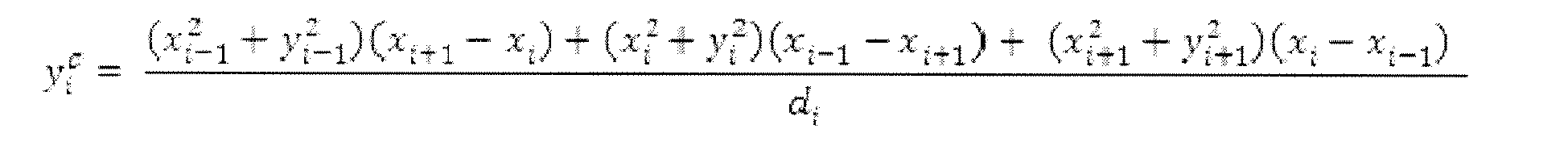

The denominator di should be precomputed because its value is zero for any straight line segment where the radius of curvature is infinite. Otherwise, the center point can be computed using the equations above. The radius of curvature ri is the norm of the vector connecting wi and the center ci . The direction of the curve can be computed for a finite radius of curvature ri using the sign of the cross product of the first and second line segments. - With reference to
FIGURES 2 and3 , an example of how the radius of curvature ri is determined for waypoint wi is graphically illustrated. Referring toFIGURE 2 , a graph of a path is illustrated, wherein the path includes a plurality of waypoints. The graph includes an x-axis and a y-axis, where each point on the graph corresponds to a waypoint. The graph further shows a dashed box enclosing three waypoints: w i-1, wi , and w i+1. These three waypoints will be used to illustrate how the radius of curvature ri of waypoint wi is determined. - Referring to
FIGURE 3 , the three waypoints, w i-1, wi , and w i+1, enclosed inFIGURE 2 are shown. The first step is to determinefirst line 302 between waypoints w i-1 and wi andsecond line 304 between waypoints wi and w i+1 as shown inFIGURE 2 . Thereafter, an intersection between a firstperpendicular line 306 and a secondperpendicular line 308 is determined. The intersection corresponds to the center ci of a circle through waypoints w i-1, wi , and w i+1. The firstperpendicular line 306 is perpendicular to thefirst line 302 and runs through the midpoint of thefirst line 302. The secondperpendicular line 308 is perpendicular to thesecond line 304 and runs through the midpoint of thesecond line 304. The radius of curvature ri is simply the length (or norm) of a line extending between the center ci of the circle and waypoint wi . - Once the radius of curvature ri of a waypoint wi has been determined, it is possible to determine the maximum allowed speed vi,allow impose by the cross track acceleration constraint amax at the waypoint wi . As should be appreciated, this step is repeated for each waypoint wi to determine an allowable speed profile.
- Referring back to
FIGURE 1 , after the allowable speed profile of a path is determined (Step 104), the optimal speed profile of the path is determined (Step 106). This step entails determining the optimal speed profile satisfying piecewise linear along track acceleration constraints, as well as the minimum of the desired speed and of the allowable speed from the previous step. This step includes the sub steps of determining speed constraints (Step 112), determining a speed profile satisfying a negative along track acceleration constraint (Step 114), and updating the speed profile to satisfy a positive along track acceleration constraint (Step 116). - With respect to determining the speed constraint (Step 112), the speed at every waypoint is constrained by both the desired velocity vi,max and by the constraint imposed for the cross track acceleration constraint vi,allow . The pre-path preferably defines the desired velocity. The desired velocity for a particular waypoint may, for example, be the speed limit along a road corresponding to the waypoint. Alternatively, the desired speed may be dependent upon the capabilities of the vehicle traversing the path, such as the top speed of the vehicle. Notwithstanding how the desired velocity is chosen, the minimum of these two constraints must be satisfied, whereby the maximum velocity
v i allowed at each waypoint is defined as shown below.
- With reference to
FIGURE 4 , the various speed profiles discussed above are shown, wherein each waypoint is graphed according to speed and position along the path ofFIGURE 2 . As shown on the graph, the allowed speed corresponds to the allowed speed according to the cross track acceleration constraint (i.e., Step 104). The desired speed corresponds to the desired speed, as discussed above. In this case, the desired speed for each waypoint was chosen arbitrarily for illustrative purposes. Lastly, the max speed (i.e., the speed constraint) corresponds to the minimum of the desired speed and the allowed speed. - Referring back to
FIGURE 1 , after the speed constraint is determined (Step 112), a speed profile satisfying a negative along track acceleration constraint is first determined (Step 114). Thereafter, the speed profile fromStep 114 is updated so as to satisfy a positive along track acceleration constraint (Step 116). However, as will be seen, these steps rely upon three equations: the time between waypoints Δt, the speed at the next waypoint v i+1, and the along track acceleration aat,i . Further, these steps rely uponAlgorithm 1. Accordingly, these equations, as well asAlgorithm 1, are presented below. - With respect to the above referenced equations, consider piecewise constant along track acceleration aat,i between waypoints wi and w i+1. Given a current speed vi and a time between waypoints Δt, the speed at the next waypoint v i+1 is as follows.

Let the along track position of waypoint wi be si , measured from the beginning of the path, i.e., ∥w i+1- wi ∥2 = s i+1-si .
To determine the time between waypoints Δt, one integrates the preceding equation for the speed at the next waypoint v i+1 with respect to the time between waypoints Δt, thereby yielding the following equation.
Solving for the time between waypoints Δt yields the following equation. Note that only the positive root in the equation for the time between waypoints Δt has a physical interpretation because the speeds must be positive.
Substituting the equation for the time between waypoints Δt in the equation corresponding to the speed at the next waypoint v i+1 yields the following equation for the speed at the next waypoint v i+1.
Solving for the acceleration to achieve a given change in speed over a given distance yields the following.
- With respect to
Algorithm 1, the sweeping algorithm,Algorithm 1, operates by incrementing through the waypoints. At waypoint wi , it first determines if it is possible to accelerate between wi and w i+1. If it can accelerate, it accelerates as fast as required, or saturates at amax . If it cannot accelerate, it next checks if it must slow down to satisfyv i+1. If it must, it slows down to that speed, using whatever acceleration necessary, even if using aat,i < -amax is required. Note that it only violates amax to slow down. If it does not need to slow down, then it holds the current speed. Finally, it returns the computed speed profile v, acceleration profile a, and time profile Δt. Note that Δt must be computed, because the algorithm is space-indexed. As should be appreciated, this algorithm runs in O(N) time, where N is the number of waypoints.
- In view of the foregoing background, the next step is to determine an acceleration profile satisfying a negative along track acceleration constrain (Step 114). This step is accomplished by using
Algorithm 1, shown above, to perform a reverse sweep of the waypoints. To begin, all along track positions are stored in s and all maximum speeds are stored inv . As should be appreciated, maximum speeds are determined in Step 112 (i.e., the speed constraint). Thereafter, to prepare for sweeping through the points from the end to the beginning, these arrays, s andv , are reversed in time, and s is negated. Once the inputs toAlgorithm 1 are prepared,Algorithm 1 is run on the reversed data with vO =v N to generate a speed profile and a corresponding along track acceleration profile a that satisfies ai > -amax ∀i. As should be appreciated, the result is that the speed profile satisfies the negative along track acceleration constraint -amax . - After a speed profile satisfying a negative along track acceleration constraint is determined (Step 114), the speed profile is updated to further satisfy a positive along track acceleration constraint (Step 116) using
Algorithm 1. This is accomplished via the use of a forward sweep of the waypoints. To begin, the speed constraintv is set to the resulting v from Step 114 (i.e., the reverse sweep). Thereafter, to prepare for sweeping through the points from beginning to end, the arrays, s andv , are again reversed in time, ands is again negated. Once the inputs toAlgorithm 1 are prepared, theAlgorithm 1 is run on the forward data with v 0 =v 1 to update the speed profile, and the corresponding along track acceleration profile, from the preceding steps, such that ai < amax ∀i. Additionally, in this sweep, ai < -amax ∀i is not possible due to the speed limits imposed by the previous, reverse sweep. - Once these reverse and forward sweeps have been completed, the result is that the speed profile satisfies both the negative along track acceleration constraint and the positive along track acceleration constraint, as well as the speed constraint from
Step 112. In other words, the optimal speed profile has been generated. Additionally, as should be appreciated, in the process of generating the speed profile, a corresponding acceleration profile and a corresponding time profile are generated. Further, while negative along track acceleration constraint -amax is shown as the negative of the positive along track acceleration constraint amax , it should be appreciated that they need not be symmetrical. - With reference to
FIGURE 5 , a graphical illustration of the speed profile after sweep two (i.e., the optimal speed profile) of the graph ofFIGURE 2 is shown.FIGURE 5 further includes the speed profile after sweep one and the speed constraint fromStep 112. The speed constraint imposes an upper bound on speeds for the first sweep, such that the speeds within the speed profile of the first sweep do not exceed the desired speed and the cross track acceleration constraint. The speed profile after the first sweep imposes an upper bound on speeds for the second sweep, such that the speeds within the speed profile of the second sweep do not exceed the desired speed, the cross track acceleration constraint, and the negative along track acceleration constraint. Thus, as should be appreciated, speeds within the speed profile of sweep one may not exceed speeds in the speed constraint profile, and speeds within the speed profile of sweep two may not exceed speeds in the speed profile of sweep one. The speed profile after sweep one shows acceleration from right to left until the speed meets the speed constraint. The speed profile after sweep two accelerates from left to right until the speed meets the speed profile from the first sweep. - After the optimal speed profile has been determined (Step 104), the method may proceed according to one or both of two optional steps. The first option is to determine the optimal travel time t for traversal of the path (Step 108). As should be appreciated, this is as simple as summing the time between waypoints Δt.

Using the optimal travel time t provides a far better approximation of the time need to traverse a path than traditional approximations, because traditional approximations fail to account for the curvature of a road, and the corresponding need to slow for curves and/or turns. - Turning now to another aspect of the present application, disclosed is an option which allows for a determination of the comfort level of the path (Step 110). This step includes the sub step of determining the frequency response of the path (Step 118). To determine the frequency response of a path, one of two methods may be employed. The first is to collect real-time driving data for a path. As should be apparent, under such a method, one needs to physically traverse the path and collect data about the frequency response of the path. Alternatively, and preferably, the frequency response is determined from the optimal speed profile, and corresponding cross track and/or along track acceleration profiles. Using this approach, acceleration profiles are converted so they are time-indexed, as opposed to space indexed. Thereafter, to get the frequency response, a digital filtering method, such as finite impulse response, Fourier transform, and so forth, is performed on the relevant acceleration profiles.
- With the frequency response, one may determine whether the frequency response includes frequencies prone to causing motion sickness. As previously mentioned, a study from NASA released a table (see Table 1 below) detailing those frequencies prone to causing motion sickness. Particularly, Table 1 plots frequency (in hertz) versus acceleration (in gravitational units). The generated curves (25 percent, 50 percent, 75 percent) represent equal motion sickness contours based on percentage of emesis within 2 hours for 500 male subjects exposed to vertical sinusoidal motion. As can be seen, a significant increase in motion sickness occurs approximately between 0.15 hertz and 0.25 hertz with a peak at approximately 0.20 herta. Based upon this determination, an approximation of the comfort level one traversing the path would experience can be derived. Additionally, or in the alternative, a comfort level can be derived based upon whether the frequency response includes higher frequencies. Naturally, the higher the frequencies present, the more curves and/or turns roads along a path have, and the more challenging it is to traverse the roads. Accordingly, a comfort level can be based upon the higher frequencies. The data of Table 1 is a classically cited motion sickness example. However, other studies may define different levels. It is to be appreciated, therefore, the above is simply an example, and the present concepts may be implemented using data from other such studies. It is also mentioned that automobile tires can typically handle up to 0.3 g's while staying within most users' comfort levels.
- Depending upon the determined comfort level, a user may be notified if the comfort level falls below a predefined threshold. In one embodiment, this threshold is set by the user while in other embodiments the threshold is set globally for all users. Alternatively, a user may request the comfort level of a path after viewing the path. In yet another alternative, a new path is generated automatically when the comfort level of the path falls below a predefined threshold. In yet another alternative, while a path is being generated, the frequency response and traversal time of a sub-path (e.g., a road) may be used to penalize the sub-path. For example, a ground based route planning system may find that a 2 minute stretch of curvy road is acceptable to save 30 minutes of travel time, whereas a 30 minute stretch of curvy road is not acceptable to save 30 minutes of travel time. In this way, the frequency response of a path is advantageously employed to improve the comfort of a user traversing a path.

- According to another exemplary embodiment, the exemplary method discussed above are modified to analyze and augment the databases of ground based route planning systems. According to one embodiment, the exemplary method discussed above may be used to pre-compute the speed profiles, acceleration profiles, time profiles, frequency responses and/or driver comforts for the paths (e.g., roads) comprising a database of a ground based route planning system. Thereafter, ground based route planning systems can use the augmented databases to determine the path between two points (e.g., a start address and an end address), whereby sub-paths (e.g., roads) may be penalized due to the pre-computed data, e.g., the frequency responses. This advantageously allows ground based route planning systems to take into account the curvature of a road while generating a path between two points, such that the path may be based upon, for example, more accurate travel times, the frequency response of sub-paths (e.g., roads), and driver comfort. Further, as should be appreciated, by pre-computing the foregoing data, the effect on the time and space complexity of the path generation algorithms used by ground based route planning systems should be negligible. In an alternative embodiment, the databases of ground based route planning systems are augmented while generating paths between two points (i.e., at runtime). In yet another alternative embodiment, the speed profiles, acceleration profiles, time profiles, frequency responses and/or driver comforts for the sub-paths (e.g., roads) intermediate and relevant to a path between two points are generated while generating the path between the two points (i.e., at runtime).
- With reference to
FIGURE 6 , anexemplary system 600 for assessing the curvature of a path as disclosed above is illustrated. The system includes one ormore users 602, a ground basedroute planning system 604 and anautomobile 614. The ground based route planning system includes aninterface 606, apath generator 608, acontroller 610 and aroad curvature assessor 612. - The
interface 606 interfaces with the one ormore users 602 and receives requests from the one ormore users 602. Theinterface 606 may be a web interface such as MapQuest™. Alternatively, theinterface 606 may be a computer interface, such as that of a portable GPS unit like TomTom™. The requests may be requests for driving directions, the comfort level of a path, the time of travel of a path, and/or other like requests. If a request is for driving directions, the request includes a start point and an end point. If the request is for the comfort level and/or travel time of a path, the request includes the path or the location of the path. Thepath generator 608 generates a path in response to a path request, e.g., a request for driving directions. Thepath generator 608 may generate a path using A* with visibility graphs, fast marching with gradient descent, or any other algorithm operative generate a path between two points. Theroad curvature assessor 612 assesses the curvature of a path as described inFIGURE 7 , below, in response to an assessment request. - The
controller 610 acts to bridge and/or relay communications between the components of the grounds basedroute planning system 604. Thecontroller 610 receives the requests from the one or more users via theinterface 606. Thereafter, thecontroller 610 determines how to respond to the request and relays the request as appropriate. If thecontroller 610 receives a request for driving directions (i.e., a path request), thecontroller 610 relays the request to thepath generator 608 and returns the generated path to the appropriate user via theinterface 606 in a visual and/or audible manner. If thecontroller 610 receives a request for a travel time of a path or a comfort level of a path (i.e., an assessment request), the next step depends upon the information received in the request. If the request includes a path, thecontroller 610 simply relays the request to theroad curvature assessor 612 and responds to the request, via theinterface 606, with the assessment of theroad curvature assessor 612. However, if the request also includes a request for driving directions (i.e., a path request), thecontroller 610 first sends the request to thepath generator 608 to generate the path. Thereafter, the controller relays the path from thepath generator 608 to theroad curvature assessor 612 and responds to the request with the path and the assessment of theroad curvature assessor 612. - The ground based
route planning system 604 may further accompany theautomobile 614. Theautomobile 614 includescurrent position indicator 616 and/orspeed regulator 618. Thecurrent position indicator 616 may provide thecontroller 610 of the ground basedroute planning system 604 with the current position of theautomobile 614 along a path generated by the ground based route planning system. Thecurrent position indicator 616 may be a GPS unit and/or any other system for ground based navigation. With the current position of theautomobile 614 along the path, thecontroller 610 can use an optimal speed profile of the path to control aspeed regulator 618 of theautomobile 614. Thespeed regulator 618 includes, for example, cruise control. This advantageously allows anautomobile 614 to slow down for turns when using thespeed regulator 618, such as cruise control. Alternatively, thecontroller 610 may facilitate a "one-sided cruise control" where thecontroller 610 imposes a speed limit on the driver based on user-provided parameters or on preprogrammed parameters. For example, such parameters may limit the ability of a driver to enter a curve too fast for the road conditions. As should be appreciated, this advantageously improves safety. According to another embodiment thecontroller 610 can provide a driver with an audio and/or visual warning to slow down. This also advantageously improves safety. Notwithstanding that the foregoing discussion contemplates the controller coordinating the foregoing features, the controller may simply provide theautomobile 614 with the speed profile for a path, whereby theautomobile 614 may carry out one or more of the foregoing features, such as controlling thespeed regulator 618. - With reference to
FIGURE 7 , an alternative embodiment ofsystem 700 for assessing the curvature of a path is illustrated. Thesystem 700 is suitably embodied by acomputer 710, or other digital processing device including a digital processor, such as a microprocessor, microcontroller, graphic processing unit (GPU), etc. and storage. In other embodiments, thesystem 700 for assessing road curvature may be embodied by a server including a digital processor and including or having access to digital data storage, such server being suitably accessed via the Internet or a local area network, or by a personal data assistant (PDA) including a digital processor and digital data storage, or so forth. The computer or other digital processing device suitably includes or is operatively connected with one or more user input devices such as anillustrated keyboard 714 for receiving user input to control the road curvature assessor, and further includes or is operatively connected with one or more display devices such as an illustrateddisplay 712 for displaying output generated based on the output of theroad curvature assessor 700. In other embodiments, the input for controlling theroad curvature assessor 700 is received from another program running previously to or concurrently with theroad curvature assessor 700 on thecomputer 710, or from a network connection, or so forth. Similarly, in other embodiments the output may serve as input to another program running subsequent to or concurrently withsystem 700 on the computer, or may be transmitted via a network connection, or so forth. - The road
curvature assessor system 700 includes an optionalpre-path module 702; anallowable speed module 704; anoptimal speed module 706; and auser module 708. When used, the optionalpre-path module 702 receives a pre-path from a source external (e.g., the Internet) to the roadcurvature assessor system 700, and generates a path from the pre-path as described in connection withStep 102 ofFIGURE 1 . Thereafter, theallowable speed module 704 receives the path from thepre-path module 702. If the optionalpre-path module 702 is not employed, theallowable speed module 704 receives a path from a source external (e.g., the Internet) to the roadcurvature assessor system 700, and generates an allowable speed profile. The allowable speed profile is preferably generated as described in connection withStep 104 ofFIGURE 1 . Theoptimal speed module 706 receives the path and the allowable speed profile from theallowable speed module 704. Theoptimal speed module 706 thereafter uses the received path and allowable speed profile to generate an optimal speed profile satisfying acceleration constraints and speed constraints. The optimal speed module generates the optimal speed profile as described in connection withStep 106 ofFIGURE 1 . Thereafter, the optimal speed profile is output for display, printout and/or implementation into additional decision making mechanisms, such as planners. Alternatively, after the optimal speed profile is generated, theuser module 708 receives the optimal speed profile, and a corresponding acceleration profile, from the optimal speed module. Additionally, theuser module 708 receives an external request for one or more of the following: an optimal travel time, a comfort level, or other like requests. Depending upon the request, theuser module 708 analyzes the speed profile and/or the acceleration profile as discussed in connection withSteps FIGURE 1 . Thereafter, a response to the request is output for display, printout and/or implementation into additional decision making mechanisms, such as planner. - In some embodiments, the exemplary methods, discussed above, the road curvature assessor employing the same, and so forth, of the present application are embodied by a storage medium storing instructions executable (for example, by a digital processor) to implement the exemplary methods and/or road curvature assessor. The storage medium may include, for example: a magnetic disk or other magnetic storage medium; an optical disk or other optical storage medium; a random access memory (RAM), read-only memory (ROM), or other electronic memory device or chip or set of operatively interconnected chips; an Internet server from which the stored instructions may be retrieved via the Internet or a local area network; or so forth.
- With reference to
FIGURES 8-17 , experimental test results of the time optimal sweeping algorithm, discussed above, are illustrated. The time optimal sweeping algorithm was applied to two exemplary path planning algorithms: an A* algorithm and a fast marching algorithm. Further, all the experiments were run using a 3.4 GHz Pentium IV computer. As will be discussed with more detail below, the time to run the time optimal sweeping algorithm demonstrates that this algorithm is computationally negligible, as expected by its O(n) time complexity. - Considering the path generated using A* to find the shortest path through a visibility graph, shown in
FIGURE 8 , the generation of the shortest path required under 20 ms using Matlab. However, this method ignored dynamic constraints, which would require an automobile to slow to a halt at sharp corners. To run the optimum time sweeping algorithm, the shortest path was discretized at 0.2 m increments, resulting in a computation time of under 1 ms to run optimum time sweeping. The results are shown inFIGURES 10-13 . The minimum time to traverse the path under acceleration and speed constraints was 13.6 sec. - One drawback to the presented approach is that corners may be cut, depending on the fineness of the discretization, a problem common to many path planning algorithms. However, the computational cost for choosing a sufficiently fine discretization is low, given the low run time of the sweeping algorithm, whereby an arbitrary precision may be used to avoid obstacles. The effect of increasing the precision of the space discretization is that it increases the total time to complete the trajectory, as the velocity slows to zero at each turn in the underlying desired path. In some problem formulations, it is desirable for corners to be cut if there is sufficient margin in the definition of obstacles used in generating the original plan. This allows sharp corners in the paths to be traversed without stopping, which is only advantageous when there are sharp corners in the path as in the case of the visibility graph.
- Considering the path generated using fast marching with the planar wave approximation, shown in
FIGURE 9 , this method, using a discrete grid, propagates the cost to reach the goal from the goal outward, increasing with distance. Close proximity to obstacles increases this cost, resulting in the refraction of the wave front around surfaces. Using the resulting cost map, gradient descent is used to find the best path to the target, according to the cost map. In the example shown, the complete path finding algorithm again ran in under 20 ms. Due to the aversion to obstacles, this cost map is not exactly the time to the goal because the vehicle is penalized for being close to obstacles. To run the optimum time sweeping algorithm, the fast marching path was discretized at 0.2 m increments again, and resulted in a computation time of under 1 ms. - The results are shown in
FIGURES 14-17 . The minimum time to traverse the path under acceleration and speed constraints was 13.8 sec. The results for fast marching differ from those of the visibility graph. Although the aversion to obstacles results in smoother paths, the paths are always longer than the visibility graph. As a result, sometimes the visibility graph is faster, and sometimes the fast marching path is faster. The aversion to obstacles causes fast marching to tend to avoid going through small gaps when possible, which is advantageous if there are winding corners, but hurts performance if there is a simple gap. The resulting minimum time acceleration commands for the fast marching path varied much more smoothly than for the visibility graph, due to a lack of corners. Although the maximum velocity constraint due to cross track acceleration was active for more time than it was for the visibility graph path, the minimum values were not as low, so the average speeds were close to equal for the two examples. - In both examples, the computation time to find a path through the environment was low because dynamic constraints were first ignored to find the path, and then included by the optimum time sweeping algorithm. By separately considering vehicle dynamics and path plans, the overall paths are not optimal. However, given the already good paths, the optimum time sweeping algorithm generates a control input and speed plan that traverses the path in minimum time.
Claims (15)
- A method for assessing road curvature of a path, including a plurality of waypoints, said method comprising the steps of:a) determining an allowable speed profile of the path, wherein said allowable speed profile includes an allowable speed for the each of the plurality of waypoints, wherein the allowable speed for the each of the plurality of waypoints satisfies a cross track acceleration constraint; and,b) determining an optimal speed profile of the path, wherein said optimal speed profile includes an optimal speed for the each of the plurality of waypoints, wherein the optimal speed for the each of the plurality of waypoints satisfies both an along track acceleration constraint and a speed constraint, wherein said speed constraint is a minimum of the desired speed and the allowable speed.
- The method of claim 1, wherein the desired speed of each of the plurality of waypoints is a driving speed limit.
- The method of claim 1 or claim 2, wherein determining the optimal speed profile includes:sweeping through the plurality of waypoints in a first direction to determine an along track acceleration profile, wherein the along track acceleration profile satisfies a negative acceleration constraint; and,sweeping through the plurality of waypoints in a second direction to update the along track acceleration profile, wherein the updated along track acceleration profile satisfies both a negative acceleration constraint and a positive acceleration constraint.
- The method of any of the preceding claims, further comprising determining an optimal travel time of the path based upon the optimal speed profile.
- The method of any of the preceding claims, further comprising determining a comfort level of the path based upon a frequency response of the path.
- The method of claim 5, wherein the frequency response of the path is based upon real time driving data or upon the optimal speed profile.
- A system for assessing road curvature in response to requests from one or more users, said system comprising:an interface operative to communicate with the one or more users, wherein the interface receives the requests from the one or more users;a path generator operative to generate a first path between a first point and a second point in response to a path request, wherein the first path includes a plurality of waypoints;a road curvature assessor operative to generate an optimal speed profile for a second path in response to an assessment request, wherein the optimal speed profile for the second path satisfies both acceleration constraints and speed constraints; and,a controller operative to respond to each of the requests via the interface, wherein said controller selectively relays the requests to the path generator and/or the road curvature assessor, wherein said controller selectively relays paths from the path generator to the road curvature assessor.
- The system of claim 7, wherein the road curvature assessor includes an allowable speed module adapted to determine an allowable speed profile of the second path and an optimal speed module adapted to determine the optimal speed profile of the second path, wherein the optimal speed profile is dependent upon the allowable speed profile.
- The system of claim 7 or claim 8, wherein the interface communicates with the one or more users via a communications network and/or via a user input device.
- The system of any of claims 7 to 9, wherein the acceleration constraints include a cross track acceleration constraint and an along track acceleration constraint.
- The system of any of claims 7 to 10, wherein the controller controls a speed regulator of an automobile based upon the optimal speed profile and a current position input.
- The system of any of claims 7 to 11, wherein the controller provides an optimal travel time of a third path corresponding to a request, wherein the optimal travel time is based upon an optimal speed profile corresponding to the third path.
- The system of any of claims 7 to 12, wherein the controller provides a comfort level of a fourth path corresponding to a request, wherein the comfort level is based upon a frequency response of the fourth path corresponding to the request.
- A system for assessing road curvature of a path, wherein said path includes a plurality of waypoints, wherein each of said plurality of waypoints includes a desired speed, said system comprising:an allowable speed module adapted to determine an allowable speed profile of the path, wherein said allowable speed profile includes an allowable speed for the each of the plurality of waypoints, wherein the allowable speed for the each of the plurality of waypoints satisfies a cross track acceleration constraint; and,an optimal speed module adapted to determine an optimal speed profile of the path, wherein said optimal speed profile includes an optimal speed for the each of the plurality of waypoints, wherein the optimal speed for the each of the plurality of waypoints satisfies both an along track acceleration constraint and a speed constraint, wherein said speed constraint is a minimum of the desired speed and the allowable speed.
- A computer program product storing instructions which, when implemented on a computer, cause the implementation of a method according to any of claims 1 to 6.
Applications Claiming Priority (2)
| Application Number | Priority Date | Filing Date | Title |
|---|---|---|---|
| US23489809P | 2009-08-18 | 2009-08-18 | |
| US12/544,706 US8306732B2 (en) | 2009-08-18 | 2009-08-20 | Model based method to assess road curvature effect on travel time and comfort for route planning |
Publications (2)
| Publication Number | Publication Date |
|---|---|
| EP2287568A1 true EP2287568A1 (en) | 2011-02-23 |
| EP2287568B1 EP2287568B1 (en) | 2015-11-04 |
Family
ID=42833357
Family Applications (1)
| Application Number | Title | Priority Date | Filing Date |
|---|---|---|---|
| EP10171608.2A Not-in-force EP2287568B1 (en) | 2009-08-18 | 2010-08-02 | Model based method to assess road curvature effect on travel time and comfort for route planning |
Country Status (4)
| Country | Link |
|---|---|
| US (2) | US8306732B2 (en) |
| EP (1) | EP2287568B1 (en) |
| JP (1) | JP5476252B2 (en) |
| KR (1) | KR101620807B1 (en) |
Cited By (4)
| Publication number | Priority date | Publication date | Assignee | Title |
|---|---|---|---|---|
| CN108139222A (en) * | 2015-10-06 | 2018-06-08 | 歌乐株式会社 | Driving comfort calculating apparatus, driving comfort calculation method and driving comfort calculation system |
| GB2556876A (en) * | 2016-11-09 | 2018-06-13 | Inventive Cogs Campbell Ltd | Vehicle route guidance |
| GB2567854A (en) * | 2017-10-27 | 2019-05-01 | Jaguar Land Rover Ltd | Motion sickness well being route planner |
| CN118010059A (en) * | 2024-04-08 | 2024-05-10 | 逸航汽车零部件无锡有限公司 | Path planning system and method based on personalized comfort control |
Families Citing this family (30)
| Publication number | Priority date | Publication date | Assignee | Title |
|---|---|---|---|---|
| US7920962B2 (en) | 2006-06-19 | 2011-04-05 | Kiva Systems, Inc. | System and method for coordinating movement of mobile drive units |
| US7912574B2 (en) | 2006-06-19 | 2011-03-22 | Kiva Systems, Inc. | System and method for transporting inventory items |
| US20130302132A1 (en) | 2012-05-14 | 2013-11-14 | Kiva Systems, Inc. | System and Method for Maneuvering a Mobile Drive Unit |
| US8538692B2 (en) | 2006-06-19 | 2013-09-17 | Amazon Technologies, Inc. | System and method for generating a path for a mobile drive unit |
| US7873469B2 (en) * | 2006-06-19 | 2011-01-18 | Kiva Systems, Inc. | System and method for managing mobile drive units |
| US8220710B2 (en) | 2006-06-19 | 2012-07-17 | Kiva Systems, Inc. | System and method for positioning a mobile drive unit |
| US8649899B2 (en) | 2006-06-19 | 2014-02-11 | Amazon Technologies, Inc. | System and method for maneuvering a mobile drive unit |
| JP4873042B2 (en) * | 2009-04-13 | 2012-02-08 | トヨタ自動車株式会社 | Vehicle control apparatus and vehicle control method |
| US8285485B2 (en) * | 2010-03-18 | 2012-10-09 | Harman International Industries, Incorporated | Vehicle navigation system with route determination based on a measure of sportiness |
| US8543308B2 (en) * | 2010-04-19 | 2013-09-24 | GM Global Technology Operations LLC | Systems and methods for communicating optimal driving information |
| US20120195491A1 (en) * | 2010-07-21 | 2012-08-02 | Palo Alto Research Center Incorporated | System And Method For Real-Time Mapping Of An Indoor Environment Using Mobile Robots With Limited Sensing |
| US8892240B1 (en) | 2011-06-29 | 2014-11-18 | Amazon Technologies, Inc. | Modular material handling system for order fulfillment |
| US9045041B2 (en) | 2013-02-27 | 2015-06-02 | Here Global B.V. | Driver behavior from probe data for augmenting a data model |
| KR102037036B1 (en) * | 2013-04-11 | 2019-10-28 | 현대모비스 주식회사 | System for controlling an automated drive of a vehicle |
| JP6161942B2 (en) * | 2013-04-19 | 2017-07-12 | 株式会社デンソーアイティーラボラトリ | Curve shape modeling device, vehicle information processing system, curve shape modeling method, and curve shape modeling program |
| CN103354044B (en) * | 2013-05-23 | 2017-04-12 | 深圳市有伴科技有限公司 | Interaction method used in voice applications (app) of electronic terminal and product comprising same |
| KR101504252B1 (en) * | 2013-11-28 | 2015-03-19 | 현대모비스 주식회사 | System for controlling speed of vehicle on curved road and method thereof |
| US20150158495A1 (en) * | 2013-12-05 | 2015-06-11 | Elwha Llc | Systems and methods for reporting characteristics of operator performance |
| US10049129B2 (en) * | 2014-12-22 | 2018-08-14 | Here Global B.V. | Method and apparatus for providing map updates from distance based bucket processing |
| JP6414005B2 (en) * | 2015-10-09 | 2018-10-31 | トヨタ自動車株式会社 | Vehicle control device |
| JP6672711B2 (en) * | 2015-11-04 | 2020-03-25 | 富士通株式会社 | Path graph generation method, apparatus, and program |
| US10234300B2 (en) * | 2015-11-13 | 2019-03-19 | Here Global B.V. | Private and personalized estimation of travel time |
| US10059287B2 (en) * | 2016-02-17 | 2018-08-28 | Toyota Motor Engineering & Manufacturing North America, Inc. | System and method for enhanced comfort prediction |
| US10107635B2 (en) * | 2016-08-19 | 2018-10-23 | Waymo Llc | Method and system for determining and dynamically updating a route and driving style for passenger comfort |
| CN108088456B (en) * | 2017-12-21 | 2021-07-16 | 北京工业大学 | A Time-Consistent Local Path Planning Method for Unmanned Vehicles |
| US11359925B2 (en) * | 2018-08-02 | 2022-06-14 | Salesforce.Com, Inc. | Utilizing estimated traversal values to accelerate the determination of high quality solutions to routing problems |
| TWI744742B (en) * | 2019-12-17 | 2021-11-01 | 神達數位股份有限公司 | Method of identifying potential dangerous road and information sharing, cloud server, computer-readable medium and application-specific integrated circuit |
| IT202000023227A1 (en) * | 2020-10-01 | 2022-04-01 | Laura Quinale | METHOD AND DEVICE FOR DETERMINING A ROUTE |
| CN112527010B (en) * | 2020-11-09 | 2022-04-01 | 福州大学 | Indoor substation unmanned aerial vehicle multi-machine cooperative inspection method based on artificial potential field and particle optimization |
| CA3249405A1 (en) * | 2022-01-28 | 2023-03-09 | Boris Valerevich PANKOV | Generating a resource-efficient track for a motor vehicle |
Citations (3)
| Publication number | Priority date | Publication date | Assignee | Title |
|---|---|---|---|---|
| WO2002003351A1 (en) * | 2000-07-04 | 2002-01-10 | Daimlerchrysler Ag | Assistance system for selecting routes |
| EP1873493A1 (en) * | 2006-06-29 | 2008-01-02 | Navigon AG | Method for automatic, computer-supported determination of a navigable route for vehicles |
| EP1890110A2 (en) * | 2006-08-18 | 2008-02-20 | Volkswagen Aktiengesellschaft | Method for determining the optimum driving strategy for a motor vehicle and correspondingly equipped device and corresponding display and corresponding vehicle |
Family Cites Families (10)
| Publication number | Priority date | Publication date | Assignee | Title |
|---|---|---|---|---|
| US4361202A (en) * | 1979-06-15 | 1982-11-30 | Michael Minovitch | Automated road transportation system |
| JP4470311B2 (en) * | 1999-10-15 | 2010-06-02 | 日産自動車株式会社 | Travel pattern generator |
| US7096428B2 (en) | 2001-09-28 | 2006-08-22 | Fuji Xerox Co., Ltd. | Systems and methods for providing a spatially indexed panoramic video |
| JP2004046580A (en) | 2002-05-14 | 2004-02-12 | Sanyo Electric Co Ltd | Transfer device |
| US7447593B2 (en) | 2004-03-26 | 2008-11-04 | Raytheon Company | System and method for adaptive path planning |
| US7513508B2 (en) * | 2004-06-04 | 2009-04-07 | Romeo Fernando Malit | Computer assisted driving of vehicles |
| KR100497781B1 (en) * | 2004-09-24 | 2005-06-28 | 주식회사 삼안 | Calculating method for parameters in the road design of s type clothoid, complex clothoid and egg type clothoid |
| JP2007106170A (en) | 2005-10-11 | 2007-04-26 | Fujifilm Corp | Operation support system |
| JP4946374B2 (en) * | 2006-11-13 | 2012-06-06 | トヨタ自動車株式会社 | Self-driving vehicle |
| JP5023894B2 (en) * | 2007-08-31 | 2012-09-12 | トヨタ自動車株式会社 | Travel plan generator |
-
2009
- 2009-08-20 US US12/544,706 patent/US8306732B2/en active Active - Reinstated
-
2010
- 2010-08-02 EP EP10171608.2A patent/EP2287568B1/en not_active Not-in-force
- 2010-08-17 JP JP2010182208A patent/JP5476252B2/en not_active Expired - Fee Related
- 2010-08-17 KR KR1020100079442A patent/KR101620807B1/en not_active Expired - Fee Related
-
2012
- 2012-10-02 US US13/633,414 patent/US8583340B2/en active Active
Patent Citations (3)
| Publication number | Priority date | Publication date | Assignee | Title |
|---|---|---|---|---|
| WO2002003351A1 (en) * | 2000-07-04 | 2002-01-10 | Daimlerchrysler Ag | Assistance system for selecting routes |
| EP1873493A1 (en) * | 2006-06-29 | 2008-01-02 | Navigon AG | Method for automatic, computer-supported determination of a navigable route for vehicles |
| EP1890110A2 (en) * | 2006-08-18 | 2008-02-20 | Volkswagen Aktiengesellschaft | Method for determining the optimum driving strategy for a motor vehicle and correspondingly equipped device and corresponding display and corresponding vehicle |
Non-Patent Citations (1)
| Title |
|---|
| MCCAULEY MICHAEL E., ROYAL JACKSON W., WYLIE C. DENNIS, O'HANLON JAMES F., MACKIE ROBERT R.: "Motion Sickness Incidence: Exploratory Studies of Habituation, Pitch and Roll and the Refinement of a Mathematical Model", April 1976 (1976-04-01), XP002605481, Retrieved from the Internet <URL:http://faculty.nps.edu/memccaul/docs/McCauley%20et%20al%201976.pdf> [retrieved on 20101014] * |
Cited By (5)
| Publication number | Priority date | Publication date | Assignee | Title |
|---|---|---|---|---|
| CN108139222A (en) * | 2015-10-06 | 2018-06-08 | 歌乐株式会社 | Driving comfort calculating apparatus, driving comfort calculation method and driving comfort calculation system |
| GB2556876A (en) * | 2016-11-09 | 2018-06-13 | Inventive Cogs Campbell Ltd | Vehicle route guidance |
| GB2567854A (en) * | 2017-10-27 | 2019-05-01 | Jaguar Land Rover Ltd | Motion sickness well being route planner |
| GB2567854B (en) * | 2017-10-27 | 2020-01-08 | Jaguar Land Rover Ltd | Motion sickness well being route planner |
| CN118010059A (en) * | 2024-04-08 | 2024-05-10 | 逸航汽车零部件无锡有限公司 | Path planning system and method based on personalized comfort control |
Also Published As
| Publication number | Publication date |
|---|---|
| KR101620807B1 (en) | 2016-05-23 |
| US20130090823A1 (en) | 2013-04-11 |
| US8583340B2 (en) | 2013-11-12 |
| JP5476252B2 (en) | 2014-04-23 |
| KR20110018847A (en) | 2011-02-24 |
| JP2011039518A (en) | 2011-02-24 |
| US20110046877A1 (en) | 2011-02-24 |
| EP2287568B1 (en) | 2015-11-04 |
| US8306732B2 (en) | 2012-11-06 |
Similar Documents
| Publication | Publication Date | Title |
|---|---|---|
| EP2287568B1 (en) | Model based method to assess road curvature effect on travel time and comfort for route planning | |
| US10161758B2 (en) | Method for creating speed profiles for digital maps | |
| US20220011132A1 (en) | Personalized Routing Based on Driver Fatigue Map | |
| US8896464B2 (en) | Navigation device and method for providing warnings for a speed trap | |
| Fellendorf et al. | Validation of the microscopic traffic flow model VISSIM in different real-world situations | |
| US9387860B2 (en) | Driver behavior from probe data for augmenting a data model | |
| Farah et al. | An empirical analysis to assess the operational design domain of lane keeping system equipped vehicles combining objective and subjective risk measures | |
| US9291474B2 (en) | System and method for providing global positioning system (GPS) feedback to a user | |
| Charly et al. | Identifying risky driving behavior: a field study using instrumented vehicles | |
| EP3919867A1 (en) | Affective-cognitive load based navigation | |
| Vaiana et al. | Demanded versus assumed friction along horizontal curves: An on-the-road experimental investigation | |
| Trabelsi et al. | Advice provision in teleoperation of autonomous vehicles | |
| Machiani et al. | Safety Impact evaluation of a narrow-automated vehicle-exclusive reversible lane on an existing smart freeway | |
| Zhou et al. | Characterization of the lateral control performance by human drivers on highways | |
| Wilson et al. | Evaluation of a Road-Departure Crash Warning System. | |
| Tomar et al. | Lane change trajectory prediction using artificial neural network | |
| US20250058795A1 (en) | Methods and systems for managing output devices in a vehicle based on proxemic risk | |
| Pellegrino | Road context evaluated by means of fuzzy interval | |
| Pariota | Driving behaviour for ADAS: theoretical and experimental analyses | |
| Tadesse | Analysis of capacity and traffic flow characteristics of mixed traffic on Addis Ababa ring road | |
| Boriboonsomsin et al. | Environmentally Friendly Driving Feedback Systems Research and Development for Heavy Duty Trucks | |
| Wu et al. | Cohort-based analysis structure for modeling driver behavior with an in-vehicle data recorder | |
| Ayernor | Calibration of HCM 2016 Capacity Model and an Empirical Assessment of Driving Behavior and Delays at Louisiana Roundabouts | |
| Klein | Techniques for Detecting Contraflow on Divided Roadways and Adjusting Vehicle Routes | |
| Thakur et al. | Evaluating Inattention Behaviour of Indian Bus Drivers Using AI-Powered Driver Monitoring Systems |
Legal Events
| Date | Code | Title | Description |
|---|---|---|---|
| PUAI | Public reference made under article 153(3) epc to a published international application that has entered the european phase |
Free format text: ORIGINAL CODE: 0009012 |
|
| AK | Designated contracting states |
Kind code of ref document: A1 Designated state(s): AL AT BE BG CH CY CZ DE DK EE ES FI FR GB GR HR HU IE IS IT LI LT LU LV MC MK MT NL NO PL PT RO SE SI SK SM TR |
|
| AX | Request for extension of the european patent |
Extension state: BA ME RS |
|
| 17P | Request for examination filed |
Effective date: 20110823 |
|
| GRAP | Despatch of communication of intention to grant a patent |
Free format text: ORIGINAL CODE: EPIDOSNIGR1 |
|
| INTG | Intention to grant announced |
Effective date: 20150630 |
|
| GRAS | Grant fee paid |
Free format text: ORIGINAL CODE: EPIDOSNIGR3 |
|
| GRAA | (expected) grant |
Free format text: ORIGINAL CODE: 0009210 |
|
| AK | Designated contracting states |
Kind code of ref document: B1 Designated state(s): AL AT BE BG CH CY CZ DE DK EE ES FI FR GB GR HR HU IE IS IT LI LT LU LV MC MK MT NL NO PL PT RO SE SI SK SM TR |
|
| REG | Reference to a national code |
Ref country code: GB Ref legal event code: FG4D |
|
| REG | Reference to a national code |
Ref country code: CH Ref legal event code: EP |
|
| REG | Reference to a national code |
Ref country code: AT Ref legal event code: REF Ref document number: 759511 Country of ref document: AT Kind code of ref document: T Effective date: 20151115 |
|
| REG | Reference to a national code |
Ref country code: IE Ref legal event code: FG4D |
|
| REG | Reference to a national code |
Ref country code: DE Ref legal event code: R096 Ref document number: 602010028718 Country of ref document: DE |
|
| REG | Reference to a national code |
Ref country code: NL Ref legal event code: MP Effective date: 20151104 |
|
| REG | Reference to a national code |
Ref country code: LT Ref legal event code: MG4D |
|
| REG | Reference to a national code |
Ref country code: AT Ref legal event code: MK05 Ref document number: 759511 Country of ref document: AT Kind code of ref document: T Effective date: 20151104 |
|
| PG25 | Lapsed in a contracting state [announced via postgrant information from national office to epo] |
Ref country code: NO Free format text: LAPSE BECAUSE OF FAILURE TO SUBMIT A TRANSLATION OF THE DESCRIPTION OR TO PAY THE FEE WITHIN THE PRESCRIBED TIME-LIMIT Effective date: 20160204 Ref country code: HR Free format text: LAPSE BECAUSE OF FAILURE TO SUBMIT A TRANSLATION OF THE DESCRIPTION OR TO PAY THE FEE WITHIN THE PRESCRIBED TIME-LIMIT Effective date: 20151104 Ref country code: NL Free format text: LAPSE BECAUSE OF FAILURE TO SUBMIT A TRANSLATION OF THE DESCRIPTION OR TO PAY THE FEE WITHIN THE PRESCRIBED TIME-LIMIT Effective date: 20151104 Ref country code: IT Free format text: LAPSE BECAUSE OF FAILURE TO SUBMIT A TRANSLATION OF THE DESCRIPTION OR TO PAY THE FEE WITHIN THE PRESCRIBED TIME-LIMIT Effective date: 20151104 Ref country code: LT Free format text: LAPSE BECAUSE OF FAILURE TO SUBMIT A TRANSLATION OF THE DESCRIPTION OR TO PAY THE FEE WITHIN THE PRESCRIBED TIME-LIMIT Effective date: 20151104 Ref country code: IS Free format text: LAPSE BECAUSE OF FAILURE TO SUBMIT A TRANSLATION OF THE DESCRIPTION OR TO PAY THE FEE WITHIN THE PRESCRIBED TIME-LIMIT Effective date: 20160304 Ref country code: ES Free format text: LAPSE BECAUSE OF FAILURE TO SUBMIT A TRANSLATION OF THE DESCRIPTION OR TO PAY THE FEE WITHIN THE PRESCRIBED TIME-LIMIT Effective date: 20151104 |
|
| PG25 | Lapsed in a contracting state [announced via postgrant information from national office to epo] |
Ref country code: FI Free format text: LAPSE BECAUSE OF FAILURE TO SUBMIT A TRANSLATION OF THE DESCRIPTION OR TO PAY THE FEE WITHIN THE PRESCRIBED TIME-LIMIT Effective date: 20151104 Ref country code: SE Free format text: LAPSE BECAUSE OF FAILURE TO SUBMIT A TRANSLATION OF THE DESCRIPTION OR TO PAY THE FEE WITHIN THE PRESCRIBED TIME-LIMIT Effective date: 20151104 Ref country code: PT Free format text: LAPSE BECAUSE OF FAILURE TO SUBMIT A TRANSLATION OF THE DESCRIPTION OR TO PAY THE FEE WITHIN THE PRESCRIBED TIME-LIMIT Effective date: 20160304 Ref country code: GR Free format text: LAPSE BECAUSE OF FAILURE TO SUBMIT A TRANSLATION OF THE DESCRIPTION OR TO PAY THE FEE WITHIN THE PRESCRIBED TIME-LIMIT Effective date: 20160205 Ref country code: PL Free format text: LAPSE BECAUSE OF FAILURE TO SUBMIT A TRANSLATION OF THE DESCRIPTION OR TO PAY THE FEE WITHIN THE PRESCRIBED TIME-LIMIT Effective date: 20151104 Ref country code: LV Free format text: LAPSE BECAUSE OF FAILURE TO SUBMIT A TRANSLATION OF THE DESCRIPTION OR TO PAY THE FEE WITHIN THE PRESCRIBED TIME-LIMIT Effective date: 20151104 Ref country code: AT Free format text: LAPSE BECAUSE OF FAILURE TO SUBMIT A TRANSLATION OF THE DESCRIPTION OR TO PAY THE FEE WITHIN THE PRESCRIBED TIME-LIMIT Effective date: 20151104 |
|
| REG | Reference to a national code |
Ref country code: FR Ref legal event code: PLFP Year of fee payment: 7 |
|
| PG25 | Lapsed in a contracting state [announced via postgrant information from national office to epo] |
Ref country code: CZ Free format text: LAPSE BECAUSE OF FAILURE TO SUBMIT A TRANSLATION OF THE DESCRIPTION OR TO PAY THE FEE WITHIN THE PRESCRIBED TIME-LIMIT Effective date: 20151104 |
|
| REG | Reference to a national code |
Ref country code: DE Ref legal event code: R097 Ref document number: 602010028718 Country of ref document: DE |
|
| PG25 | Lapsed in a contracting state [announced via postgrant information from national office to epo] |
Ref country code: RO Free format text: LAPSE BECAUSE OF FAILURE TO SUBMIT A TRANSLATION OF THE DESCRIPTION OR TO PAY THE FEE WITHIN THE PRESCRIBED TIME-LIMIT Effective date: 20151104 Ref country code: EE Free format text: LAPSE BECAUSE OF FAILURE TO SUBMIT A TRANSLATION OF THE DESCRIPTION OR TO PAY THE FEE WITHIN THE PRESCRIBED TIME-LIMIT Effective date: 20151104 Ref country code: SK Free format text: LAPSE BECAUSE OF FAILURE TO SUBMIT A TRANSLATION OF THE DESCRIPTION OR TO PAY THE FEE WITHIN THE PRESCRIBED TIME-LIMIT Effective date: 20151104 Ref country code: SM Free format text: LAPSE BECAUSE OF FAILURE TO SUBMIT A TRANSLATION OF THE DESCRIPTION OR TO PAY THE FEE WITHIN THE PRESCRIBED TIME-LIMIT Effective date: 20151104 Ref country code: DK Free format text: LAPSE BECAUSE OF FAILURE TO SUBMIT A TRANSLATION OF THE DESCRIPTION OR TO PAY THE FEE WITHIN THE PRESCRIBED TIME-LIMIT Effective date: 20151104 |
|
| PLBE | No opposition filed within time limit |
Free format text: ORIGINAL CODE: 0009261 |
|
| STAA | Information on the status of an ep patent application or granted ep patent |
Free format text: STATUS: NO OPPOSITION FILED WITHIN TIME LIMIT |
|
| 26N | No opposition filed |
Effective date: 20160805 |
|
| PG25 | Lapsed in a contracting state [announced via postgrant information from national office to epo] |
Ref country code: SI Free format text: LAPSE BECAUSE OF FAILURE TO SUBMIT A TRANSLATION OF THE DESCRIPTION OR TO PAY THE FEE WITHIN THE PRESCRIBED TIME-LIMIT Effective date: 20151104 |
|
| PG25 | Lapsed in a contracting state [announced via postgrant information from national office to epo] |
Ref country code: BE Free format text: LAPSE BECAUSE OF FAILURE TO SUBMIT A TRANSLATION OF THE DESCRIPTION OR TO PAY THE FEE WITHIN THE PRESCRIBED TIME-LIMIT Effective date: 20151104 |
|
| PG25 | Lapsed in a contracting state [announced via postgrant information from national office to epo] |
Ref country code: MC Free format text: LAPSE BECAUSE OF FAILURE TO SUBMIT A TRANSLATION OF THE DESCRIPTION OR TO PAY THE FEE WITHIN THE PRESCRIBED TIME-LIMIT Effective date: 20151104 |
|
| REG | Reference to a national code |
Ref country code: CH Ref legal event code: PL |
|
| PG25 | Lapsed in a contracting state [announced via postgrant information from national office to epo] |
Ref country code: CH Free format text: LAPSE BECAUSE OF NON-PAYMENT OF DUE FEES Effective date: 20160831 Ref country code: LI Free format text: LAPSE BECAUSE OF NON-PAYMENT OF DUE FEES Effective date: 20160831 |
|
| REG | Reference to a national code |
Ref country code: IE Ref legal event code: MM4A |
|
| REG | Reference to a national code |
Ref country code: FR Ref legal event code: PLFP Year of fee payment: 8 |
|
| PG25 | Lapsed in a contracting state [announced via postgrant information from national office to epo] |
Ref country code: IE Free format text: LAPSE BECAUSE OF NON-PAYMENT OF DUE FEES Effective date: 20160802 |
|
| PG25 | Lapsed in a contracting state [announced via postgrant information from national office to epo] |
Ref country code: LU Free format text: LAPSE BECAUSE OF NON-PAYMENT OF DUE FEES Effective date: 20160802 |
|
| PG25 | Lapsed in a contracting state [announced via postgrant information from national office to epo] |
Ref country code: CY Free format text: LAPSE BECAUSE OF FAILURE TO SUBMIT A TRANSLATION OF THE DESCRIPTION OR TO PAY THE FEE WITHIN THE PRESCRIBED TIME-LIMIT Effective date: 20151104 Ref country code: HU Free format text: LAPSE BECAUSE OF FAILURE TO SUBMIT A TRANSLATION OF THE DESCRIPTION OR TO PAY THE FEE WITHIN THE PRESCRIBED TIME-LIMIT; INVALID AB INITIO Effective date: 20100802 |
|
| PG25 | Lapsed in a contracting state [announced via postgrant information from national office to epo] |
Ref country code: TR Free format text: LAPSE BECAUSE OF FAILURE TO SUBMIT A TRANSLATION OF THE DESCRIPTION OR TO PAY THE FEE WITHIN THE PRESCRIBED TIME-LIMIT Effective date: 20151104 Ref country code: MK Free format text: LAPSE BECAUSE OF FAILURE TO SUBMIT A TRANSLATION OF THE DESCRIPTION OR TO PAY THE FEE WITHIN THE PRESCRIBED TIME-LIMIT Effective date: 20151104 Ref country code: MT Free format text: LAPSE BECAUSE OF NON-PAYMENT OF DUE FEES Effective date: 20160831 |
|
| REG | Reference to a national code |
Ref country code: FR Ref legal event code: PLFP Year of fee payment: 9 |
|
| PG25 | Lapsed in a contracting state [announced via postgrant information from national office to epo] |
Ref country code: BG Free format text: LAPSE BECAUSE OF FAILURE TO SUBMIT A TRANSLATION OF THE DESCRIPTION OR TO PAY THE FEE WITHIN THE PRESCRIBED TIME-LIMIT Effective date: 20151104 |
|
| PG25 | Lapsed in a contracting state [announced via postgrant information from national office to epo] |
Ref country code: AL Free format text: LAPSE BECAUSE OF FAILURE TO SUBMIT A TRANSLATION OF THE DESCRIPTION OR TO PAY THE FEE WITHIN THE PRESCRIBED TIME-LIMIT Effective date: 20151104 |
|
| PGFP | Annual fee paid to national office [announced via postgrant information from national office to epo] |
Ref country code: FR Payment date: 20200721 Year of fee payment: 11 Ref country code: GB Payment date: 20200722 Year of fee payment: 11 |
|
| GBPC | Gb: european patent ceased through non-payment of renewal fee |
Effective date: 20210802 |
|
| PG25 | Lapsed in a contracting state [announced via postgrant information from national office to epo] |
Ref country code: GB Free format text: LAPSE BECAUSE OF NON-PAYMENT OF DUE FEES Effective date: 20210802 Ref country code: FR Free format text: LAPSE BECAUSE OF NON-PAYMENT OF DUE FEES Effective date: 20210831 |
|
| PGFP | Annual fee paid to national office [announced via postgrant information from national office to epo] |
Ref country code: DE Payment date: 20220720 Year of fee payment: 13 |
|
| REG | Reference to a national code |
Ref country code: DE Ref legal event code: R119 Ref document number: 602010028718 Country of ref document: DE |
|
| PG25 | Lapsed in a contracting state [announced via postgrant information from national office to epo] |
Ref country code: DE Free format text: LAPSE BECAUSE OF NON-PAYMENT OF DUE FEES Effective date: 20240301 |