EP2287387A2 - Dryer door and dryer comprising the same - Google Patents
Dryer door and dryer comprising the same Download PDFInfo
- Publication number
- EP2287387A2 EP2287387A2 EP09758499A EP09758499A EP2287387A2 EP 2287387 A2 EP2287387 A2 EP 2287387A2 EP 09758499 A EP09758499 A EP 09758499A EP 09758499 A EP09758499 A EP 09758499A EP 2287387 A2 EP2287387 A2 EP 2287387A2
- Authority
- EP
- European Patent Office
- Prior art keywords
- door
- dryer
- inlet
- convex portion
- door glass
- Prior art date
- Legal status (The legal status is an assumption and is not a legal conclusion. Google has not performed a legal analysis and makes no representation as to the accuracy of the status listed.)
- Granted
Links
Images

Classifications
-
- D—TEXTILES; PAPER
- D06—TREATMENT OF TEXTILES OR THE LIKE; LAUNDERING; FLEXIBLE MATERIALS NOT OTHERWISE PROVIDED FOR
- D06F—LAUNDERING, DRYING, IRONING, PRESSING OR FOLDING TEXTILE ARTICLES
- D06F39/00—Details of washing machines not specific to a single type of machines covered by groups D06F9/00 - D06F27/00
- D06F39/12—Casings; Tubs
- D06F39/14—Doors or covers; Securing means therefor
-
- D—TEXTILES; PAPER
- D06—TREATMENT OF TEXTILES OR THE LIKE; LAUNDERING; FLEXIBLE MATERIALS NOT OTHERWISE PROVIDED FOR
- D06F—LAUNDERING, DRYING, IRONING, PRESSING OR FOLDING TEXTILE ARTICLES
- D06F58/00—Domestic laundry dryers
- D06F58/10—Drying cabinets or drying chambers having heating or ventilating means
- D06F58/12—Drying cabinets or drying chambers having heating or ventilating means having conveying means for moving clothes, e.g. along an endless track
-
- D—TEXTILES; PAPER
- D06—TREATMENT OF TEXTILES OR THE LIKE; LAUNDERING; FLEXIBLE MATERIALS NOT OTHERWISE PROVIDED FOR
- D06F—LAUNDERING, DRYING, IRONING, PRESSING OR FOLDING TEXTILE ARTICLES
- D06F58/00—Domestic laundry dryers
- D06F58/20—General details of domestic laundry dryers
-
- D—TEXTILES; PAPER
- D06—TREATMENT OF TEXTILES OR THE LIKE; LAUNDERING; FLEXIBLE MATERIALS NOT OTHERWISE PROVIDED FOR
- D06F—LAUNDERING, DRYING, IRONING, PRESSING OR FOLDING TEXTILE ARTICLES
- D06F58/00—Domestic laundry dryers
- D06F58/20—General details of domestic laundry dryers
- D06F58/203—Laundry conditioning arrangements
-
- D—TEXTILES; PAPER
- D06—TREATMENT OF TEXTILES OR THE LIKE; LAUNDERING; FLEXIBLE MATERIALS NOT OTHERWISE PROVIDED FOR
- D06F—LAUNDERING, DRYING, IRONING, PRESSING OR FOLDING TEXTILE ARTICLES
- D06F58/00—Domestic laundry dryers
- D06F58/20—General details of domestic laundry dryers
- D06F58/26—Heating arrangements, e.g. gas heating equipment
-
- D—TEXTILES; PAPER
- D06—TREATMENT OF TEXTILES OR THE LIKE; LAUNDERING; FLEXIBLE MATERIALS NOT OTHERWISE PROVIDED FOR
- D06F—LAUNDERING, DRYING, IRONING, PRESSING OR FOLDING TEXTILE ARTICLES
- D06F2103/00—Parameters monitored or detected for the control of domestic laundry washing machines, washer-dryers or laundry dryers
- D06F2103/28—Air properties
- D06F2103/36—Flow or velocity
-
- D—TEXTILES; PAPER
- D06—TREATMENT OF TEXTILES OR THE LIKE; LAUNDERING; FLEXIBLE MATERIALS NOT OTHERWISE PROVIDED FOR
- D06F—LAUNDERING, DRYING, IRONING, PRESSING OR FOLDING TEXTILE ARTICLES
- D06F2103/00—Parameters monitored or detected for the control of domestic laundry washing machines, washer-dryers or laundry dryers
- D06F2103/56—Parameters monitored or detected for the control of domestic laundry washing machines, washer-dryers or laundry dryers related to air ducts, e.g. position of flow diverters
-
- D—TEXTILES; PAPER
- D06—TREATMENT OF TEXTILES OR THE LIKE; LAUNDERING; FLEXIBLE MATERIALS NOT OTHERWISE PROVIDED FOR
- D06F—LAUNDERING, DRYING, IRONING, PRESSING OR FOLDING TEXTILE ARTICLES
- D06F2105/00—Systems or parameters controlled or affected by the control systems of washing machines, washer-dryers or laundry dryers
- D06F2105/28—Electric heating
-
- D—TEXTILES; PAPER
- D06—TREATMENT OF TEXTILES OR THE LIKE; LAUNDERING; FLEXIBLE MATERIALS NOT OTHERWISE PROVIDED FOR
- D06F—LAUNDERING, DRYING, IRONING, PRESSING OR FOLDING TEXTILE ARTICLES
- D06F2105/00—Systems or parameters controlled or affected by the control systems of washing machines, washer-dryers or laundry dryers
- D06F2105/30—Blowers
Definitions
- the present invention relates to a door for a dryer capable of enlarging an inner volume of the dryer, and a dryer having the same.
- a dryer is provided with a door installed at an upper surface or front surface thereof for putting clothes in or puling them out.
- the door is configured as a door glass such that a user can view the inner situation of the dryer through the glass from the outside.
- the door glass is typically formed of tempered glass or coated on its surface with a tempered coating so as to avoid the damage caused by an impact against the clothes or accessories attached to the clothes.
- the door glass As an inlet for putting the clothes in is formed to be thick inwardly by a preset depth or a drum disposed within the inlet is installed with a specific interval from an inner wall surface of a case, the door glass is provided with a convex portion protruded in an inward direction of the drum by a preset height, so as to prevent the clothes from being entangled at the circumference of the inlet while drying the clothes.
- the front surface of the convex portion may be curved so as to be more convex in the protruded direction of the convex portion or may be formed to be planar.
- a door for a dryer including a door frame coupled to a main body having an inlet, and a door glass coupled to the door frame, wherein a central portion of the door glass positioned at a central portion of the inlet is disposed lower than a height of an edge of at least one portion of the door glass positioned at an inner side end of the inlet.
- the door glass may be provided with a convex portion protruded toward an inner space of the main body to be inserted in the inlet, and a concave portion recessed into an end surface of the convex portion in an opposite direction to the convex portion.
- the door glass may have a convex portion protruded toward the inner space of the main body to be inserted in the inlet, and an end surface of the convex portion may have an inclined portion inclined downwardly.
- a dryer including a main body having an inlet for clothes, a drum installed inside the main body and communicated with the inlet to have an inner space for accommodating clothes to be dried, and a door configured to open and close the inlet of the main body, wherein the door may include a door frame coupled to the main body, and a door glass coupled to the door frame, wherein a central portion of the door glass positioned at a central portion of the inlet is lower than a height of an edge of at least one portion of the door glass positioned at an inner side end of the inlet.
- the door glass may be provided with a convex portion protruded toward an inner space of the drum to be inserted in the inlet, and a concave portion recessed into an end surface of the convex portion in an opposite direction to the convex portion.
- a lint filter for filtering foreign materials out of air heat-exchanged with the clothes may be disposed at an inside of the inlet of the main body, and the convex portion of the door glass may have the end surface formed to have a length as long as not interfering with the lint filter.
- the door glass may have a convex portion protruded toward the inner space of the drum to be inserted in the inlet, and an end surface of the convex portion may have an incline portion inclined downwardly.
- a lint filter for filtering foreign materials out of air heat-exchanged with the clothes may be disposed at an inside of the inlet of the main body, and the inclined portion may be inclined such that the height of the convex portion is lowered toward the lint filter.
- An end of the inclined portion close to the lint filter may be formed not to overlap with the lint filter.
- a door for a dryer according to the present invention can have a concave portion or an inclined portion formed at an end surface of a door glass, such that an inner volume of the dryer can be enlarged without increasing the size of the dryer, under consideration of the dryer having the same capacity, resulting in allowing a large quantity of clothes to be dried at once.
- a dryer having a door may include a case 1 configuring an outer appearance, a drum 2 rotatably installed in the case 1 for accommodating clothes therein, a hot air supplying unit 3 for generating hot air to be supplied into the drum 2, and a heat exchanging unit 4 for dehumidifying humid air discharged out of the drum 2.
- An inlet 11 through which clothes are put into the drum 1 may be formed at a front surface of the case 1.
- a front cover 5 for supporting a front side of the drum 2 may be installed at an inner side end of the inlet 11.
- An exhaust duct 6 for guiding humid air flowed through the drum 2 to the outside of the case 1 may be installed below the front cover 5.
- a rear cover 7 for supporting a rear side of the drum 2 is installed at a rear wall surface inside the case 1.
- the rear cover 7 may be provided with an air supply hole through which hot air is supplied into the drum 2.
- a suction duct 8 may be installed at a rear wall surface outside the drum 2 so as to communicate with the air supply hole.
- the hot air supplying unit 3 is installed at an inlet of the suction duct 8.
- a lint filter 9 for filtering foreign materials out of air circulating in the exhaust duct 6 may be installed at the front cover 5.
- the heat exchanging unit 4 for dehumidifying humid air guided into the exhaust duct 6 may be installed at the exhaust duct 6.
- the hot air supplying unit 3 is operated to suck external air and heats the sucked air up.
- the heated (hot) air is then guided toward the drum 2 via the suction duct 8.
- the hot air guided to the drum 2 is supplied into the drum 2 via the air supply hole formed at the rear cover 7.
- the hot air is heat-exchanged with wet clothes within the drum 2 to dry the clothes.
- the humid air is then guided toward the exhaust duct 6 disposed inside the case 1.
- the humid air flows through the lint filter 9 positioned at an upstream side of the exhaust duct 6 such that foreign materials are filtered out.
- the foreign material filtered humid air is discharged out of the case 1 via the exhaust duct 6.
- the case 1 is provided with a door 100 coupled to the circumference of the inlet 11 by a hinge for opening and closing the inlet 11.
- the door 100 may include a door frame 110 having one side coupled to the circumference of the inlet 11 by a hinge and another side detachably hooked at the case 1, and a door glass 120 coupled to the door frame 110 and formed of a transparent material such that an inner situation is viewable therethrough.
- the door frame 110 is fabricated in an annular shape by using a material, which is non-transparent and has a specific intensity.
- the fabricated door frame 110 is then rotatably coupled to the case 1 by the hinge.
- a handle (not shown) is provided at one side of the door frame 110, namely, at an opposite side to the side being hinge-coupled.
- the door glass 120 is formed of a transparent material, namely, glass. On a surface thereof facing the drum 2 may be coated with a surface reinforcing film for preventing the surface from being scratched or broken by clothes or accessories attached on the clothes.
- the door glass 120 may be configured such that its inner surface, namely, the surface facing the drum 2 can be concave or inclined, thus to increase an inner volume of the drum 2.
- the door glass 120 may be provided with a convex portion 122 formed at (extending from) one side of the fixed portion 121, fixed to the door frame 110, with a preset height toward the inside of the drum 2, and a concave portion 123 formed at an end surface of the convex portion 122 to be concave toward the outside of the drum 2 with a preset depth.
- the concave portion 123 as shown in FIGS. 3 and 4 , may be formed to be curved or formed to be planar in a dimpled shape although not shown.
- the convex portion 122 may be formed such that an outer circumferential surface thereof is as long as interfering with an inlet of the lint filter 9.
- the end surface of the convex portion 122 may be preferably formed to have a preset interval t from the lint filter 9 such that the end surface cannot overlap with the lint filter 9 on a horizontal line. Hence, the inner volume of the drum 2 can be enlarged and also a smooth air flow is allowed.
- the inner volume of the drum can be increased without increasing the size of the dryer, under consideration of the dryer with the same capacity, resulting in allowing a large quantity of clothes to be dried at once.
- an inner surface of the door glass 120 namely, the end surface of the convex portion 122 may be formed to be inclined.
- the door glass 120 also has the fixed portion 121 and the convex portion 122.
- a concave portion may not be formed at the end surface of the convex portion 122 as shown in the previous embodiment, but the end surface of the convex portion 122 may be formed to be inclined, namely, an inclined portion 124 may be formed.
- the inclined portion 124 as shown in the drawings, may be formed to be planar or formed to have a concavely curved surface.
- an end of the inclined portion 124 close to the lint filter 9 may be preferably positioned in an approximately straight line with the lint filter 9, or have a preset interval t from the lint filter 9 such that the end of the inclined portion 124 can be positioned outer than the lint filter 9.
- the inner volume of the drum 2 can be enlarged and also air circulating in an inner space of the drum 2 can be smoothly guided to the lint filter 9.
- the concave portion 123 is formed at the end surface of the door glass 120, when putting clothes in the drum 2, the inner volume of the drum 2 can be enlarged, as compared to other dryer with the same capacity, without increasing the size of the dryer, resulting in allowing a large quantity of clothes to be dried at once.
- the door for the dryer according to the present invention may be applicable equally to a washing machine as well as the dryer.
Landscapes
- Engineering & Computer Science (AREA)
- Textile Engineering (AREA)
- Detail Structures Of Washing Machines And Dryers (AREA)
- Main Body Construction Of Washing Machines And Laundry Dryers (AREA)
Abstract
Description
- The present invention relates to a door for a dryer capable of enlarging an inner volume of the dryer, and a dryer having the same.
- In general, a dryer is provided with a door installed at an upper surface or front surface thereof for putting clothes in or puling them out. The door is configured as a door glass such that a user can view the inner situation of the dryer through the glass from the outside. The door glass is typically formed of tempered glass or coated on its surface with a tempered coating so as to avoid the damage caused by an impact against the clothes or accessories attached to the clothes.
- As an inlet for putting the clothes in is formed to be thick inwardly by a preset depth or a drum disposed within the inlet is installed with a specific interval from an inner wall surface of a case, the door glass is provided with a convex portion protruded in an inward direction of the drum by a preset height, so as to prevent the clothes from being entangled at the circumference of the inlet while drying the clothes. The front surface of the convex portion may be curved so as to be more convex in the protruded direction of the convex portion or may be formed to be planar.
- However, with the configuration of the door glass employed in the related art dryer, as stated above, as the convex portion is formed in the inward direction of the drum and the front surface of the convex portion is formed to be more convex or planar, the space occupied by the convex portion increases so much, which causes a problem that the inner volume of the drum within the dryer is reduced under the same capacity of the dryer.
- Therefore, to solve the problem of the door employed in the related art dryer, it is an object of the present invention to provide a door for a dryer capable of enlarging an inner volume of the dryer, with maintaining the outer appearance of the dryer, by varying the shape of the door glass, and a dryer having the same.
- To achieve these objects, there is provided a door for a dryer including a door frame coupled to a main body having an inlet, and a door glass coupled to the door frame, wherein a central portion of the door glass positioned at a central portion of the inlet is disposed lower than a height of an edge of at least one portion of the door glass positioned at an inner side end of the inlet.
- Here, the door glass may be provided with a convex portion protruded toward an inner space of the main body to be inserted in the inlet, and a concave portion recessed into an end surface of the convex portion in an opposite direction to the convex portion.
- Alternatively, the door glass may have a convex portion protruded toward the inner space of the main body to be inserted in the inlet, and an end surface of the convex portion may have an inclined portion inclined downwardly.
- In one aspect of the present invention, there is provided a dryer including a main body having an inlet for clothes, a drum installed inside the main body and communicated with the inlet to have an inner space for accommodating clothes to be dried, and a door configured to open and close the inlet of the main body, wherein the door may include a door frame coupled to the main body, and a door glass coupled to the door frame, wherein a central portion of the door glass positioned at a central portion of the inlet is lower than a height of an edge of at least one portion of the door glass positioned at an inner side end of the inlet.
- Here, the door glass may be provided with a convex portion protruded toward an inner space of the drum to be inserted in the inlet, and a concave portion recessed into an end surface of the convex portion in an opposite direction to the convex portion.
- A lint filter for filtering foreign materials out of air heat-exchanged with the clothes may be disposed at an inside of the inlet of the main body, and the convex portion of the door glass may have the end surface formed to have a length as long as not interfering with the lint filter.
- Further, the door glass may have a convex portion protruded toward the inner space of the drum to be inserted in the inlet, and an end surface of the convex portion may have an incline portion inclined downwardly.
- A lint filter for filtering foreign materials out of air heat-exchanged with the clothes may be disposed at an inside of the inlet of the main body, and the inclined portion may be inclined such that the height of the convex portion is lowered toward the lint filter.
- An end of the inclined portion close to the lint filter may be formed not to overlap with the lint filter.
- A door for a dryer according to the present invention can have a concave portion or an inclined portion formed at an end surface of a door glass, such that an inner volume of the dryer can be enlarged without increasing the size of the dryer, under consideration of the dryer having the same capacity, resulting in allowing a large quantity of clothes to be dried at once.
-
-
FIG. 1 is a perspective view showing an appearance of a dryer having a door according to the present invention; -
FIG. 2 is a longitudinal sectional view showing an inside of the dryer ofFIG. 1 ; -
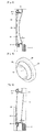
FIGS. 3 and 4 are longitudinal sectional view and perspective view, respectively, showing one embodiment of the door for the dryer ofFIG. 1 ; and -
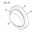
FIGS. 5 and6 are longitudinal sectional view and perspective view, respectively, showing another embodiment of the door for the dryer ofFIG. 1 . - Reference will now be made in detail to a door for a dryer and a dryer having the same in accordance with the preferred embodiments of the present invention, examples of which are illustrated in the accompanying drawings. It will also be apparent to those skilled in the art that various modifications and variations can be made in the present invention without departing from the spirit or scope of the invention. Thus, it is intended that the present invention cover modifications and variations of this invention provided they come within the scope of the appended claims and their equivalents.
- As shown in
FIGS. 1 and 2 , a dryer having a door according to the present invention may include a case 1 configuring an outer appearance, a drum 2 rotatably installed in the case 1 for accommodating clothes therein, a hot air supplying unit 3 for generating hot air to be supplied into the drum 2, and a heat exchanging unit 4 for dehumidifying humid air discharged out of the drum 2. - An
inlet 11 through which clothes are put into the drum 1 may be formed at a front surface of the case 1. A front cover 5 for supporting a front side of the drum 2 may be installed at an inner side end of theinlet 11. Anexhaust duct 6 for guiding humid air flowed through the drum 2 to the outside of the case 1 may be installed below the front cover 5. - A
rear cover 7 for supporting a rear side of the drum 2 is installed at a rear wall surface inside the case 1. Therear cover 7 may be provided with an air supply hole through which hot air is supplied into the drum 2. A suction duct 8 may be installed at a rear wall surface outside the drum 2 so as to communicate with the air supply hole. The hot air supplying unit 3 is installed at an inlet of the suction duct 8. - A
lint filter 9 for filtering foreign materials out of air circulating in theexhaust duct 6 may be installed at the front cover 5. The heat exchanging unit 4 for dehumidifying humid air guided into theexhaust duct 6 may be installed at theexhaust duct 6. - With the configuration of the dryer according to the present invention, upon power being applied, the hot air supplying unit 3 is operated to suck external air and heats the sucked air up. The heated (hot) air is then guided toward the drum 2 via the suction duct 8. The hot air guided to the drum 2 is supplied into the drum 2 via the air supply hole formed at the
rear cover 7. The hot air is heat-exchanged with wet clothes within the drum 2 to dry the clothes. Afterwards, the humid air is then guided toward theexhaust duct 6 disposed inside the case 1. The humid air flows through thelint filter 9 positioned at an upstream side of theexhaust duct 6 such that foreign materials are filtered out. The foreign material filtered humid air is discharged out of the case 1 via theexhaust duct 6. During the procedure, the series of processes, which the humid air is dehumidified via the heat exchanging unit 4 disposed in the middle of a passage of theexhaust duct 6 so as to be discharged out of the case 1, are repeated. - Here, the case 1 is provided with a
door 100 coupled to the circumference of theinlet 11 by a hinge for opening and closing theinlet 11. Thedoor 100, as shown inFIG. 1 , may include adoor frame 110 having one side coupled to the circumference of theinlet 11 by a hinge and another side detachably hooked at the case 1, and adoor glass 120 coupled to thedoor frame 110 and formed of a transparent material such that an inner situation is viewable therethrough. - The
door frame 110 is fabricated in an annular shape by using a material, which is non-transparent and has a specific intensity. The fabricateddoor frame 110 is then rotatably coupled to the case 1 by the hinge. A handle (not shown) is provided at one side of thedoor frame 110, namely, at an opposite side to the side being hinge-coupled. - The
door glass 120 is formed of a transparent material, namely, glass. On a surface thereof facing the drum 2 may be coated with a surface reinforcing film for preventing the surface from being scratched or broken by clothes or accessories attached on the clothes. - The
door glass 120 may be configured such that its inner surface, namely, the surface facing the drum 2 can be concave or inclined, thus to increase an inner volume of the drum 2. - For example, as shown in
FIGS. 3 and 4 , thedoor glass 120 may be provided with aconvex portion 122 formed at (extending from) one side of the fixedportion 121, fixed to thedoor frame 110, with a preset height toward the inside of the drum 2, and aconcave portion 123 formed at an end surface of theconvex portion 122 to be concave toward the outside of the drum 2 with a preset depth. Alternatively, theconcave portion 123, as shown inFIGS. 3 and 4 , may be formed to be curved or formed to be planar in a dimpled shape although not shown. Theconvex portion 122 may be formed such that an outer circumferential surface thereof is as long as interfering with an inlet of thelint filter 9. If possible, as shown inFIG. 3 , the end surface of theconvex portion 122 may be preferably formed to have a preset interval t from thelint filter 9 such that the end surface cannot overlap with thelint filter 9 on a horizontal line. Hence, the inner volume of the drum 2 can be enlarged and also a smooth air flow is allowed. - In the dryer having the door according to the present invention, as the
concave portion 123 is formed at the end surface of thedoor glass 120, when putting clothes in the drum 2, the inner volume of the drum can be increased without increasing the size of the dryer, under consideration of the dryer with the same capacity, resulting in allowing a large quantity of clothes to be dried at once. - In the meantime, as shown in
FIGS. 5 and6 , an inner surface of thedoor glass 120, namely, the end surface of theconvex portion 122 may be formed to be inclined. In this case, thedoor glass 120 also has the fixedportion 121 and theconvex portion 122. However, a concave portion may not be formed at the end surface of theconvex portion 122 as shown in the previous embodiment, but the end surface of theconvex portion 122 may be formed to be inclined, namely, aninclined portion 124 may be formed. Here, theinclined portion 124, as shown in the drawings, may be formed to be planar or formed to have a concavely curved surface. Here, an end of theinclined portion 124 close to thelint filter 9 may be preferably positioned in an approximately straight line with thelint filter 9, or have a preset interval t from thelint filter 9 such that the end of theinclined portion 124 can be positioned outer than thelint filter 9. Hence, the inner volume of the drum 2 can be enlarged and also air circulating in an inner space of the drum 2 can be smoothly guided to thelint filter 9. - In the dryer having the door according to the present invention, as the
concave portion 123 is formed at the end surface of thedoor glass 120, when putting clothes in the drum 2, the inner volume of the drum 2 can be enlarged, as compared to other dryer with the same capacity, without increasing the size of the dryer, resulting in allowing a large quantity of clothes to be dried at once. - The door for the dryer according to the present invention may be applicable equally to a washing machine as well as the dryer.
- Dryer, door, door glass, concave
Claims (15)
- A door for a dryer comprising:a door frame coupled to a main body having an inlet; anda door glass coupled to the door frame,wherein a central portion of the door glass positioned at a central portion of the inlet is disposed lower than a height of an edge of at least one portion of the door glass positioned at an inner side end of the inlet.
- The door of claim 1, wherein the door glass is provided with a convex portion protruded toward an inner space of the main body to be inserted in the inlet, and a concave portion recessed into an end surface of the convex portion in an opposite direction to the convex portion.
- The door of claim 2, wherein the concave portion is formed to have a curved section or a dimpled section.
- The door of claim 1, wherein the door glass has a convex portion protruded toward the inner space of the main body to be inserted in the inlet, an end surface of the convex portion having an inclined portion inclined downwardly.
- The door of claim 4, wherein the inclined portion is formed to have a planar section or a concave section.
- The door of any of claims 1 to 5, wherein the door glass is formed of a transparent material for allowing the inner space of the main body to be viewable from the outside.
- A dryer comprising:a main body having an inlet for clothes;a drum installed inside the main body and communicated with the inlet to have an inner space for accommodating clothes to be dried; anda door configured to open and close the inlet of the main body,wherein the door comprises:a door frame coupled to the main body; anda door glass coupled to the door frame,wherein a central portion of the door glass positioned at a central portion of the inlet is lower than a height of an edge of at least one portion of the door glass positioned at an inner side end of the inlet.
- The dryer of claim 7, wherein the door glass is provided with a convex portion protruded toward an inner space of the drum to be inserted in the inlet, and a concave portion recessed into an end surface of the convex portion in an opposite direction to the convex portion.
- The dryer of claim 7, wherein the concave portion is formed to have a curved section or a dimpled section.
- The dryer of claim 7, wherein a lint filter for filtering foreign materials out of air heat-exchanged with the clothes is disposed at an inside of the inlet of the main body, wherein the convex portion of the door glass has the end surface formed to have a length as long as not interfering with the lint filter.
- The dryer of claim 7, wherein the door glass has a convex portion protruded toward the inner space of the drum to be inserted in the inlet, an end surface of the convex portion having an inclined portion inclined downwardly.
- The dryer of claim 11, wherein the inclined portion is formed to have a planar section or a concave section.
- The dryer of claim 11, wherein a lint filter for filtering foreign materials out of air heat-exchanged with the clothes is disposed at an inside of the inlet of the main body, wherein the inclined portion is inclined such that the height of the convex portion is lowered toward the lint filter.
- The dryer of claim 11, wherein an end of the inclined portion close to the lint filter is formed not to overlap with the lint filter.
- The dryer of any of claims 7 to 14, wherein the door glass is formed of a transparent material for allowing the inner space of the drum to be viewable from the outside.
Applications Claiming Priority (2)
| Application Number | Priority Date | Filing Date | Title |
|---|---|---|---|
| KR1020080052320A KR101010080B1 (en) | 2008-06-03 | 2008-06-03 | Door of dryer |
| PCT/KR2009/002929 WO2009148246A2 (en) | 2008-06-03 | 2009-06-02 | Dryer door and dryer comprising the same |
Publications (3)
| Publication Number | Publication Date |
|---|---|
| EP2287387A2 true EP2287387A2 (en) | 2011-02-23 |
| EP2287387A4 EP2287387A4 (en) | 2011-11-23 |
| EP2287387B1 EP2287387B1 (en) | 2020-08-05 |
Family
ID=40204674
Family Applications (1)
| Application Number | Title | Priority Date | Filing Date |
|---|---|---|---|
| EP09758499.9A Not-in-force EP2287387B1 (en) | 2008-06-03 | 2009-06-02 | Dryer door and dryer comprising the same |
Country Status (5)
| Country | Link |
|---|---|
| US (1) | US8607473B2 (en) |
| EP (1) | EP2287387B1 (en) |
| KR (1) | KR101010080B1 (en) |
| CN (2) | CN101328675B (en) |
| WO (1) | WO2009148246A2 (en) |
Cited By (2)
| Publication number | Priority date | Publication date | Assignee | Title |
|---|---|---|---|---|
| US20130276322A1 (en) * | 2012-04-24 | 2013-10-24 | Whirlpool Corporation | Laundry treating appliance door with planar window element and projection |
| WO2016107685A1 (en) * | 2014-12-30 | 2016-07-07 | Arcelik Anonim Sirketi | A laundry washing and/or drying machine with reduced noise level |
Families Citing this family (26)
| Publication number | Priority date | Publication date | Assignee | Title |
|---|---|---|---|---|
| KR101463828B1 (en) * | 2008-09-16 | 2014-11-20 | 엘지전자 주식회사 | Clothes processor |
| KR20100080415A (en) | 2008-12-30 | 2010-07-08 | 엘지전자 주식회사 | Laundry machine |
| KR20100129117A (en) | 2009-05-28 | 2010-12-08 | 엘지전자 주식회사 | Washing machine |
| US9828715B2 (en) | 2009-05-28 | 2017-11-28 | Lg Electronics Inc. | Laundry maching having a drying function |
| KR101689600B1 (en) | 2009-05-28 | 2016-12-26 | 엘지전자 주식회사 | Laundry Machine |
| EP3480354B1 (en) | 2011-08-31 | 2020-05-13 | LG Electronics Inc. -1- | Laundry treating apparatus |
| AU341654S (en) * | 2011-09-02 | 2012-03-28 | Bsh Bosch & Siemens Hausgeraete Gmbh | Door of washing machines/drying machines |
| USD681890S1 (en) | 2012-06-11 | 2013-05-07 | Whirlpool Corporation | Appliance window |
| CN104878576B (en) * | 2015-04-30 | 2018-01-16 | 无锡小天鹅股份有限公司 | rotating cylinder dryer |
| CN108951018A (en) * | 2017-05-18 | 2018-12-07 | 青岛海尔洗衣机有限公司 | The front door assembly and roller washing machine of roller washing machine |
| KR102436958B1 (en) * | 2017-09-19 | 2022-08-29 | 삼성전자주식회사 | Dryer |
| USD856615S1 (en) * | 2017-10-19 | 2019-08-13 | Whirlpool Corporation | Door bowl for a laundry treating appliance door |
| CN108342881A (en) * | 2017-12-18 | 2018-07-31 | 倍科电器有限公司 | Roller washing machine glass door |
| CN111101335B (en) * | 2018-10-26 | 2022-08-23 | 无锡小天鹅电器有限公司 | Door body assembly and drum washing machine |
| CN111101348B (en) * | 2018-10-26 | 2022-02-22 | 无锡小天鹅电器有限公司 | Door body assembly and drum washing machine |
| USD1016418S1 (en) | 2020-11-30 | 2024-02-27 | Electrolux Home Products, Inc. | Laundry appliance door |
| USD1011658S1 (en) * | 2021-04-01 | 2024-01-16 | Lg Electronics Inc. | Door for clothes drying machine |
| CN113308856A (en) * | 2021-04-12 | 2021-08-27 | 江苏康佳智能电器有限公司 | A push door and washing machine |
| USD1017934S1 (en) * | 2021-10-15 | 2024-03-12 | Lg Electronics Inc. | Electric drying machine for laundry purpose |
| USD1017159S1 (en) * | 2021-10-15 | 2024-03-05 | Lg Electronics Inc. | Electric washing machine |
| USD1010251S1 (en) * | 2022-07-15 | 2024-01-02 | Samsung Electronics Co., Ltd. | Washing machine |
| USD1010252S1 (en) * | 2022-07-15 | 2024-01-02 | Samsung Electronics Co., Ltd. | Washing machine |
| KR102822287B1 (en) | 2023-02-20 | 2025-06-18 | (주)동진테크윈 | Gasket pressing device for door of clothes dryer |
| USD1072393S1 (en) * | 2023-03-20 | 2025-04-22 | Lg Electronics Inc. | Electric washing machine |
| USD1056371S1 (en) * | 2023-03-20 | 2024-12-31 | Lg Electronics Inc. | Electric washing machine |
| CA225476S (en) * | 2023-04-05 | 2025-06-17 | Lg Electronics Inc | Electric washing machine |
Family Cites Families (19)
| Publication number | Priority date | Publication date | Assignee | Title |
|---|---|---|---|---|
| US2681513A (en) * | 1952-02-20 | 1954-06-22 | Paul L Fowler | Clothes drier with horizontal cylinder |
| US3959891A (en) * | 1974-12-30 | 1976-06-01 | Whirlpool Corporation | Removable lint screen assembly for a dryer |
| JPH1094700A (en) | 1996-09-20 | 1998-04-14 | Takeda Giken Kogyo:Kk | Laundry drying method and laundry dryer |
| KR100271170B1 (en) | 1998-06-17 | 2000-11-01 | 윤종용 | Door of drum washing machine |
| DE10031171A1 (en) * | 2000-06-27 | 2002-01-10 | Bsh Bosch Siemens Hausgeraete | Porthole window for a front loading drum washing machine |
| DE10031170A1 (en) * | 2000-06-27 | 2002-01-10 | Bsh Bosch Siemens Hausgeraete | gasket |
| DE10228602B4 (en) | 2001-08-02 | 2004-03-25 | Miele & Cie. Kg | Front loading washing machine |
| EP1321559B1 (en) * | 2001-12-20 | 2008-12-03 | CANDY S.p.A. | Front-loading clothes washing machine |
| KR100595180B1 (en) * | 2002-07-31 | 2006-07-03 | 엘지전자 주식회사 | Door of laundry / drum washing machine |
| KR100465715B1 (en) * | 2002-12-02 | 2005-01-13 | 엘지전자 주식회사 | Sealing assembly of door part for clothes dryer |
| JP2005095226A (en) * | 2003-09-22 | 2005-04-14 | Sharp Corp | Drum type washer / dryer |
| DE60332458D1 (en) * | 2003-10-08 | 2010-06-17 | Candy Spa | Front-loading washing machine |
| CA2508607C (en) * | 2005-05-30 | 2007-09-11 | Camco Inc. | Clothes dryer door assembly |
| US7802855B2 (en) * | 2005-09-30 | 2010-09-28 | General Electric Company | Home appliance having a door |
| JP4612563B2 (en) | 2006-03-03 | 2011-01-12 | 株式会社東芝 | Clothes dryer |
| JP2008093245A (en) | 2006-10-13 | 2008-04-24 | Hitachi Appliances Inc | Drum type washer / dryer |
| KR101550843B1 (en) * | 2008-10-10 | 2015-09-08 | 삼성전자 주식회사 | Clothing dryer and Door of the same |
| US8127464B2 (en) * | 2009-07-31 | 2012-03-06 | Bsh Home Appliances Corporation | Front ring for a household appliance door |
| US8276409B2 (en) * | 2009-11-05 | 2012-10-02 | Magna Mirrors Of America, Inc. | Glass appliance cover with bonded hardware |
-
2008
- 2008-06-03 KR KR1020080052320A patent/KR101010080B1/en not_active Expired - Fee Related
- 2008-07-29 CN CN2008101448467A patent/CN101328675B/en not_active Expired - Fee Related
-
2009
- 2009-06-02 WO PCT/KR2009/002929 patent/WO2009148246A2/en not_active Ceased
- 2009-06-02 CN CN200980113540.8A patent/CN102007244B/en not_active Expired - Fee Related
- 2009-06-02 US US12/935,543 patent/US8607473B2/en active Active
- 2009-06-02 EP EP09758499.9A patent/EP2287387B1/en not_active Not-in-force
Cited By (3)
| Publication number | Priority date | Publication date | Assignee | Title |
|---|---|---|---|---|
| US20130276322A1 (en) * | 2012-04-24 | 2013-10-24 | Whirlpool Corporation | Laundry treating appliance door with planar window element and projection |
| US8875416B2 (en) * | 2012-04-24 | 2014-11-04 | Whirlpool Corporation | Laundry treating appliance door with planar window element and projection |
| WO2016107685A1 (en) * | 2014-12-30 | 2016-07-07 | Arcelik Anonim Sirketi | A laundry washing and/or drying machine with reduced noise level |
Also Published As
| Publication number | Publication date |
|---|---|
| KR20090126132A (en) | 2009-12-08 |
| US8607473B2 (en) | 2013-12-17 |
| CN101328675B (en) | 2011-07-20 |
| EP2287387A4 (en) | 2011-11-23 |
| CN102007244A (en) | 2011-04-06 |
| WO2009148246A2 (en) | 2009-12-10 |
| EP2287387B1 (en) | 2020-08-05 |
| CN102007244B (en) | 2014-02-19 |
| CN101328675A (en) | 2008-12-24 |
| KR101010080B1 (en) | 2011-01-24 |
| US20110037363A1 (en) | 2011-02-17 |
| WO2009148246A3 (en) | 2010-03-11 |
Similar Documents
| Publication | Publication Date | Title |
|---|---|---|
| US8607473B2 (en) | Dryer door and dryer comprising the same | |
| EP1609902B1 (en) | A door and a drum type washing machine and a clothes drier using the same | |
| US7694434B2 (en) | Laundry drier | |
| CN108239845A (en) | Washing machine | |
| CN106574426B (en) | clothes dryer | |
| TWI589750B (en) | Wash machine | |
| EP2711455B1 (en) | Laundry treating apparatus | |
| EP3118368B1 (en) | Clothes dryer | |
| KR20100040478A (en) | Clothing dryer and door of the same | |
| CN105917041A (en) | Clothes dryer | |
| KR100664507B1 (en) | Clothes dryer | |
| KR100732550B1 (en) | Clothes dryer | |
| JP6572435B2 (en) | Drum type washer / dryer | |
| JP4579311B2 (en) | Electric washing machine | |
| US20070089316A1 (en) | Clothing drying machine | |
| JP2012071069A (en) | Drying machine and washing and drying machine | |
| KR100732549B1 (en) | Clothes dryer | |
| KR20030041385A (en) | Cloth dryer | |
| KR200264785Y1 (en) | Cloth dryer | |
| KR100589907B1 (en) | Clothes dryer | |
| KR100572599B1 (en) | Clothes dryer | |
| JP6554663B2 (en) | Clothes dryer | |
| JP6471355B2 (en) | Clothes dryer | |
| CN122055502A (en) | Clothes treating apparatus | |
| KR20100094680A (en) | Dryer |
Legal Events
| Date | Code | Title | Description |
|---|---|---|---|
| PUAI | Public reference made under article 153(3) epc to a published international application that has entered the european phase |
Free format text: ORIGINAL CODE: 0009012 |
|
| 17P | Request for examination filed |
Effective date: 20101201 |
|
| AK | Designated contracting states |
Kind code of ref document: A2 Designated state(s): AT BE BG CH CY CZ DE DK EE ES FI FR GB GR HR HU IE IS IT LI LT LU LV MC MK MT NL NO PL PT RO SE SI SK TR |
|
| AX | Request for extension of the european patent |
Extension state: AL BA RS |
|
| DAX | Request for extension of the european patent (deleted) | ||
| A4 | Supplementary search report drawn up and despatched |
Effective date: 20111021 |
|
| RIC1 | Information provided on ipc code assigned before grant |
Ipc: D06F 58/20 20060101AFI20111017BHEP Ipc: D06F 39/14 20060101ALI20111017BHEP |
|
| STAA | Information on the status of an ep patent application or granted ep patent |
Free format text: STATUS: EXAMINATION IS IN PROGRESS |
|
| 17Q | First examination report despatched |
Effective date: 20180801 |
|
| GRAP | Despatch of communication of intention to grant a patent |
Free format text: ORIGINAL CODE: EPIDOSNIGR1 |
|
| STAA | Information on the status of an ep patent application or granted ep patent |
Free format text: STATUS: GRANT OF PATENT IS INTENDED |
|
| INTG | Intention to grant announced |
Effective date: 20200206 |
|
| GRAS | Grant fee paid |
Free format text: ORIGINAL CODE: EPIDOSNIGR3 |
|
| GRAA | (expected) grant |
Free format text: ORIGINAL CODE: 0009210 |
|
| STAA | Information on the status of an ep patent application or granted ep patent |
Free format text: STATUS: THE PATENT HAS BEEN GRANTED |
|
| AK | Designated contracting states |
Kind code of ref document: B1 Designated state(s): AT BE BG CH CY CZ DE DK EE ES FI FR GB GR HR HU IE IS IT LI LT LU LV MC MK MT NL NO PL PT RO SE SI SK TR |
|
| REG | Reference to a national code |
Ref country code: GB Ref legal event code: FG4D |
|
| REG | Reference to a national code |
Ref country code: CH Ref legal event code: EP |
|
| REG | Reference to a national code |
Ref country code: AT Ref legal event code: REF Ref document number: 1298849 Country of ref document: AT Kind code of ref document: T Effective date: 20200815 |
|
| REG | Reference to a national code |
Ref country code: DE Ref legal event code: R096 Ref document number: 602009062555 Country of ref document: DE |
|
| REG | Reference to a national code |
Ref country code: IE Ref legal event code: FG4D |
|
| REG | Reference to a national code |
Ref country code: LT Ref legal event code: MG4D |
|
| REG | Reference to a national code |
Ref country code: NL Ref legal event code: MP Effective date: 20200805 |
|
| REG | Reference to a national code |
Ref country code: AT Ref legal event code: MK05 Ref document number: 1298849 Country of ref document: AT Kind code of ref document: T Effective date: 20200805 |
|
| PG25 | Lapsed in a contracting state [announced via postgrant information from national office to epo] |
Ref country code: SE Free format text: LAPSE BECAUSE OF FAILURE TO SUBMIT A TRANSLATION OF THE DESCRIPTION OR TO PAY THE FEE WITHIN THE PRESCRIBED TIME-LIMIT Effective date: 20200805 Ref country code: BG Free format text: LAPSE BECAUSE OF FAILURE TO SUBMIT A TRANSLATION OF THE DESCRIPTION OR TO PAY THE FEE WITHIN THE PRESCRIBED TIME-LIMIT Effective date: 20201105 Ref country code: AT Free format text: LAPSE BECAUSE OF FAILURE TO SUBMIT A TRANSLATION OF THE DESCRIPTION OR TO PAY THE FEE WITHIN THE PRESCRIBED TIME-LIMIT Effective date: 20200805 Ref country code: HR Free format text: LAPSE BECAUSE OF FAILURE TO SUBMIT A TRANSLATION OF THE DESCRIPTION OR TO PAY THE FEE WITHIN THE PRESCRIBED TIME-LIMIT Effective date: 20200805 Ref country code: LT Free format text: LAPSE BECAUSE OF FAILURE TO SUBMIT A TRANSLATION OF THE DESCRIPTION OR TO PAY THE FEE WITHIN THE PRESCRIBED TIME-LIMIT Effective date: 20200805 Ref country code: ES Free format text: LAPSE BECAUSE OF FAILURE TO SUBMIT A TRANSLATION OF THE DESCRIPTION OR TO PAY THE FEE WITHIN THE PRESCRIBED TIME-LIMIT Effective date: 20200805 Ref country code: NO Free format text: LAPSE BECAUSE OF FAILURE TO SUBMIT A TRANSLATION OF THE DESCRIPTION OR TO PAY THE FEE WITHIN THE PRESCRIBED TIME-LIMIT Effective date: 20201105 Ref country code: GR Free format text: LAPSE BECAUSE OF FAILURE TO SUBMIT A TRANSLATION OF THE DESCRIPTION OR TO PAY THE FEE WITHIN THE PRESCRIBED TIME-LIMIT Effective date: 20201106 Ref country code: PT Free format text: LAPSE BECAUSE OF FAILURE TO SUBMIT A TRANSLATION OF THE DESCRIPTION OR TO PAY THE FEE WITHIN THE PRESCRIBED TIME-LIMIT Effective date: 20201207 Ref country code: FI Free format text: LAPSE BECAUSE OF FAILURE TO SUBMIT A TRANSLATION OF THE DESCRIPTION OR TO PAY THE FEE WITHIN THE PRESCRIBED TIME-LIMIT Effective date: 20200805 |
|
| PG25 | Lapsed in a contracting state [announced via postgrant information from national office to epo] |
Ref country code: LV Free format text: LAPSE BECAUSE OF FAILURE TO SUBMIT A TRANSLATION OF THE DESCRIPTION OR TO PAY THE FEE WITHIN THE PRESCRIBED TIME-LIMIT Effective date: 20200805 Ref country code: PL Free format text: LAPSE BECAUSE OF FAILURE TO SUBMIT A TRANSLATION OF THE DESCRIPTION OR TO PAY THE FEE WITHIN THE PRESCRIBED TIME-LIMIT Effective date: 20200805 Ref country code: NL Free format text: LAPSE BECAUSE OF FAILURE TO SUBMIT A TRANSLATION OF THE DESCRIPTION OR TO PAY THE FEE WITHIN THE PRESCRIBED TIME-LIMIT Effective date: 20200805 Ref country code: IS Free format text: LAPSE BECAUSE OF FAILURE TO SUBMIT A TRANSLATION OF THE DESCRIPTION OR TO PAY THE FEE WITHIN THE PRESCRIBED TIME-LIMIT Effective date: 20201205 |
|
| PG25 | Lapsed in a contracting state [announced via postgrant information from national office to epo] |
Ref country code: RO Free format text: LAPSE BECAUSE OF FAILURE TO SUBMIT A TRANSLATION OF THE DESCRIPTION OR TO PAY THE FEE WITHIN THE PRESCRIBED TIME-LIMIT Effective date: 20200805 Ref country code: EE Free format text: LAPSE BECAUSE OF FAILURE TO SUBMIT A TRANSLATION OF THE DESCRIPTION OR TO PAY THE FEE WITHIN THE PRESCRIBED TIME-LIMIT Effective date: 20200805 Ref country code: DK Free format text: LAPSE BECAUSE OF FAILURE TO SUBMIT A TRANSLATION OF THE DESCRIPTION OR TO PAY THE FEE WITHIN THE PRESCRIBED TIME-LIMIT Effective date: 20200805 Ref country code: CZ Free format text: LAPSE BECAUSE OF FAILURE TO SUBMIT A TRANSLATION OF THE DESCRIPTION OR TO PAY THE FEE WITHIN THE PRESCRIBED TIME-LIMIT Effective date: 20200805 |
|
| REG | Reference to a national code |
Ref country code: DE Ref legal event code: R097 Ref document number: 602009062555 Country of ref document: DE |
|
| PLBE | No opposition filed within time limit |
Free format text: ORIGINAL CODE: 0009261 |
|
| STAA | Information on the status of an ep patent application or granted ep patent |
Free format text: STATUS: NO OPPOSITION FILED WITHIN TIME LIMIT |
|
| PG25 | Lapsed in a contracting state [announced via postgrant information from national office to epo] |
Ref country code: SK Free format text: LAPSE BECAUSE OF FAILURE TO SUBMIT A TRANSLATION OF THE DESCRIPTION OR TO PAY THE FEE WITHIN THE PRESCRIBED TIME-LIMIT Effective date: 20200805 |
|
| 26N | No opposition filed |
Effective date: 20210507 |
|
| PG25 | Lapsed in a contracting state [announced via postgrant information from national office to epo] |
Ref country code: SI Free format text: LAPSE BECAUSE OF FAILURE TO SUBMIT A TRANSLATION OF THE DESCRIPTION OR TO PAY THE FEE WITHIN THE PRESCRIBED TIME-LIMIT Effective date: 20200805 |
|
| PG25 | Lapsed in a contracting state [announced via postgrant information from national office to epo] |
Ref country code: MC Free format text: LAPSE BECAUSE OF FAILURE TO SUBMIT A TRANSLATION OF THE DESCRIPTION OR TO PAY THE FEE WITHIN THE PRESCRIBED TIME-LIMIT Effective date: 20200805 |
|
| REG | Reference to a national code |
Ref country code: CH Ref legal event code: PL |
|
| GBPC | Gb: european patent ceased through non-payment of renewal fee |
Effective date: 20210602 |
|
| REG | Reference to a national code |
Ref country code: BE Ref legal event code: MM Effective date: 20210630 |
|
| PG25 | Lapsed in a contracting state [announced via postgrant information from national office to epo] |
Ref country code: LU Free format text: LAPSE BECAUSE OF NON-PAYMENT OF DUE FEES Effective date: 20210602 |
|
| PG25 | Lapsed in a contracting state [announced via postgrant information from national office to epo] |
Ref country code: LI Free format text: LAPSE BECAUSE OF NON-PAYMENT OF DUE FEES Effective date: 20210630 Ref country code: IE Free format text: LAPSE BECAUSE OF NON-PAYMENT OF DUE FEES Effective date: 20210602 Ref country code: GB Free format text: LAPSE BECAUSE OF NON-PAYMENT OF DUE FEES Effective date: 20210602 Ref country code: CH Free format text: LAPSE BECAUSE OF NON-PAYMENT OF DUE FEES Effective date: 20210630 |
|
| PG25 | Lapsed in a contracting state [announced via postgrant information from national office to epo] |
Ref country code: FR Free format text: LAPSE BECAUSE OF NON-PAYMENT OF DUE FEES Effective date: 20210630 |
|
| PG25 | Lapsed in a contracting state [announced via postgrant information from national office to epo] |
Ref country code: BE Free format text: LAPSE BECAUSE OF NON-PAYMENT OF DUE FEES Effective date: 20210630 |
|
| PGFP | Annual fee paid to national office [announced via postgrant information from national office to epo] |
Ref country code: IT Payment date: 20220509 Year of fee payment: 14 Ref country code: DE Payment date: 20220506 Year of fee payment: 14 |
|
| PG25 | Lapsed in a contracting state [announced via postgrant information from national office to epo] |
Ref country code: HU Free format text: LAPSE BECAUSE OF FAILURE TO SUBMIT A TRANSLATION OF THE DESCRIPTION OR TO PAY THE FEE WITHIN THE PRESCRIBED TIME-LIMIT; INVALID AB INITIO Effective date: 20090602 Ref country code: CY Free format text: LAPSE BECAUSE OF FAILURE TO SUBMIT A TRANSLATION OF THE DESCRIPTION OR TO PAY THE FEE WITHIN THE PRESCRIBED TIME-LIMIT Effective date: 20200805 |
|
| REG | Reference to a national code |
Ref country code: DE Ref legal event code: R119 Ref document number: 602009062555 Country of ref document: DE |
|
| PG25 | Lapsed in a contracting state [announced via postgrant information from national office to epo] |
Ref country code: MK Free format text: LAPSE BECAUSE OF FAILURE TO SUBMIT A TRANSLATION OF THE DESCRIPTION OR TO PAY THE FEE WITHIN THE PRESCRIBED TIME-LIMIT Effective date: 20200805 Ref country code: DE Free format text: LAPSE BECAUSE OF NON-PAYMENT OF DUE FEES Effective date: 20240103 |
|
| PG25 | Lapsed in a contracting state [announced via postgrant information from national office to epo] |
Ref country code: TR Free format text: LAPSE BECAUSE OF FAILURE TO SUBMIT A TRANSLATION OF THE DESCRIPTION OR TO PAY THE FEE WITHIN THE PRESCRIBED TIME-LIMIT Effective date: 20200805 |
|
| PG25 | Lapsed in a contracting state [announced via postgrant information from national office to epo] |
Ref country code: IT Free format text: LAPSE BECAUSE OF NON-PAYMENT OF DUE FEES Effective date: 20230602 |
|
| PG25 | Lapsed in a contracting state [announced via postgrant information from national office to epo] |
Ref country code: MT Free format text: LAPSE BECAUSE OF FAILURE TO SUBMIT A TRANSLATION OF THE DESCRIPTION OR TO PAY THE FEE WITHIN THE PRESCRIBED TIME-LIMIT Effective date: 20200805 |